Visit our website at: https://www.harborfreight.com
email our technical support at: [email protected]
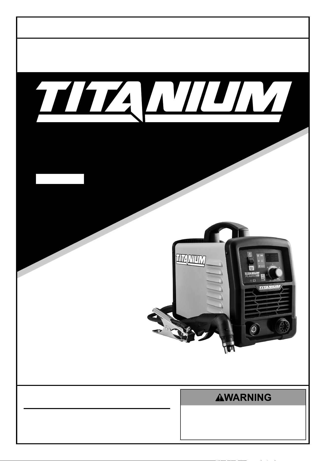
PLASMA45
56255
tM
Owner’s Manual & Safety Instructions
Save This Manual Keep this manual for the safety warnings and precautions, assembly,
operating, inspection, maintenance and cleaning procedures. Write the product’s serial number in the
back of the manual near the assembly diagram (or month and year of purchase if product has no number).
Keep this manual and the receipt in a safe and dry place for future reference. 24l
When unpacking, make sure that the product is intact
and undamaged. If any parts are missing or broken,
please call 1‑800‑444‑3353 as soon as possible.
Copyright
©
2024 by Harbor Freight Tools
®
. All rights reserved.
No portion of this manual or any artwork contained herein may be reproduced in
any shape or form without the express written consent of Harbor Freight Tools.
Diagrams within this manual may not be drawn proportionally. Due to continuing
improvements, actual product may differ slightly from the product described herein.
Tools required for assembly and service may not be included.
Read this material before using this product.
Failure to do so can result in serious injury.
SAVE THIS MANUAL.
Page 2 For technical questions, please call 1-800-444-3353. ITEM 56255
SaFety OperatiOn MaintenanceSetup
table of contents
Safety ........................................................................2
Specifications ............................................................5
Setup .........................................................................6
Operation ................................................................... 8
Maintenance .............................................................12
Troubleshooting ........................................................ 14
Circuit Diagram .......................................................... 2
Parts List and Diagram .............................................18
Warranty ...................................................................20
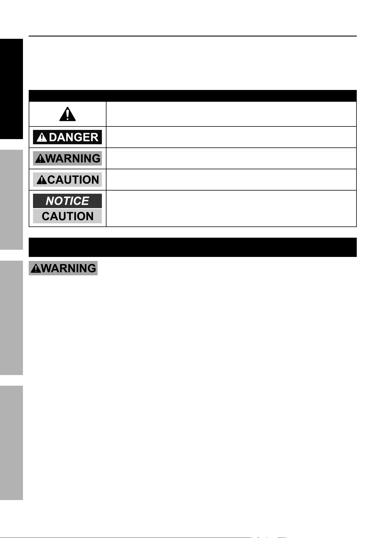
WarninG SyMBOLS anD DeFinitiOnS
This is the safety alert symbol. It is used to alert you to potential
personal injury hazards. Obey all safety messages that
follow this symbol to avoid possible injury or death.
Indicates a hazardous situation which, if not avoided,
will result in death or serious injury.
Indicates a hazardous situation which, if not avoided,
could result in death or serious injury.
Indicates a hazardous situation which, if not avoided,
could result in minor or moderate injury.
Addresses practices not related to personal injury.
iMpOrtant SaFety inStructiOnS
read all safety warnings and instructions.
Failure to follow the warnings and instructions may result in electric shock, fire and/or serious injury.
Save all warnings and instructions for future reference.
1. DanGer! people with pacemakers should
not use this plasma cutter or be nearby
during use. plasma cutters, such as this one,
produce strong, fluctuating electromagnetic
fields that can cause pacemaker interference
or pacemaker failure. people with pacemakers
should consult their physician(s) for advice.
2. Maintain a safe working environment.
Keep the work area well lit. Make sure
there is adequate surrounding workspace.
Keep the work area free of obstructions, grease,
oil, trash, and other debris. Do not use in areas
near flammable chemicals, dusts, and vapors.
Do not use in a damp or wet location.
3. never leave the plasma cutter unattended
when it is plugged into an electrical outlet.
Turn off the Plasma Cutter, and unplug it from its
electrical outlet before leaving.
unplug the plasma cutter from its electrical
outlet before performing any inspection,
maintenance, or cleaning procedures,
including changing accessories.
4. avoid unintentional starting. Make sure
switch is in off position before plugging in.
Make sure you are prepared to begin work
before turning on the Plasma Cutter.
5. prevent eye injury and burns. Wearing personal
protective equipment reduces the risk of injury.
• Wear an ANSI‑approved welding helmet
featuring at least a number 10 shade lens rating.
• Leather leggings, fire resistant shoes or
boots should be worn when using this
product. Do not wear pants with cuffs, shirts
with open pockets, or any clothing that can
catch and hold molten metal or sparks.
• Keep clothing free of grease, oil, solvents,
or any flammable substances. Wear dry,
insulating gloves and protective clothing.
• Wear an approved head covering to protect the
head and neck. Use aprons, cape, sleeves,
shoulder covers, and bibs designed and
approved for welding and cutting procedures.
• When welding/cutting overhead or in
confined spaces, wear fi resistant ear plugs
or ear muffs to keep sparks out of ears.

Page 3For technical questions, please call 1-800-444-3353.ITEM 56255
SaFetyOperatiOnMaintenance Setup
6. Maintain labels and nameplates
on the plasma cutter.
These carry important information.
If unreadable or missing, contact
Harbor Freight Tools for a replacement.
7. prevent accidental fires. Remove any
combustible material from the work area.
• When possible, move the work to a location well
away from combustible materials. If relocation
is not possible, protect the combustibles with
a cover made of fire resistant material.
• Remove or make safe all combustible
materials for a radius of 35 feet (10 meters)
around the work area. Use a fire resistant
material to cover or block all open doorways,
windows, cracks, and other openings.
• Enclose the work area with portable fire
resistant screens. Protect combustible
walls, ceilings, floors, etc., from sparks
and heat with fire resistant material.
• If working on a metal wall, ceiling, etc.,
prevent ignition of combustibles on the other
side by moving the combustibles to a safe
location. If relocation of combustibles is not
possible, designate someone to serve as a
fire watch, equipped with a fire extinguisher,
during the cutting process and for at least
one half hour after the cutting is completed.
• Do not weld or cut on materials having a
combustible coating or combustible internal
structure, as in walls or ceilings, without an
approved method for eliminating the hazard.
• Do not dispose of hot slag in containers
holding combustible materials. Keep a fire
extinguisher nearby and know how to use it.
• After welding or cutting, make a thorough
examination for evidence of fire. Be aware
that easily visible smoke or flame may not
be present for some time after the fire has
started. Do not weld or cut in atmospheres
containing dangerously reactive or flammable
gases, vapors, liquids, and dust.
• Provide adequate ventilation in work areas
to prevent accumulation of flammable gases,
vapors, and dust. Do not apply heat to a
container that has held an unknown substance
or a combustible material whose contents, when
heated, can produce flammable or explosive
vapors. Clean and purge containers before
applying heat. Vent closed containers, including
castings, before preheating, welding, or cutting.
• Only use compressed air or nitrogen to
operate the Plasma Cutter. Never use
other compressed gases. Don’t exceed
maximum PSI for this product as stated on
the specification table on page page 5.
8. inHaLatiOn HaZarD:
Welding and cutting produce
tOXic FuMeS.
Exposure to welding or cutting
exhaust fumes can increase
the risk of developing certain cancers,
such as cancer of the larynx and lung cancer.
Also, some diseases that may be linked to
exposure to welding or cutting exhaust fumes are:
• Early onset of Parkinson’s Disease
• Heart disease • Ulcers
• Damage to the reproductive organs
• Inflammation of the small intestine or stomach
• Kidney damage
• Respiratory diseases such as
emphysema, bronchitis, or pneumonia
Use natural or forced air ventilation
and wear a respirator approved by
NIOSH to protect against the fumes
produced to reduce the risk of
developing the above illnesses.
9. avoid overexposure to fumes and gases.
Always keep your head out of the fumes.
Do not breathe the fumes. Use enough ventilation
or exhaust, or both, to keep fumes and gases
from your breathing zone and general area.
• Where ventilation is questionable, have a
qualified technician take an air sampling to
determine the need for corrective measures.
Use mechanical ventilation to improve air
quality. If engineering controls are not
feasible, use an approved respirator.
• Work in a confined area only if it
is well ventilated, or while wearing
an air‑supplied respirator.
• Follow OSHA guidelines for
Permissible Exposure Limits (PELs)
for various fumes and gases.
• Follow the American Conference
of Governmental Industrial
Hygienists recommendations for
Threshold Limit Values (TLVs)
for fumes and gases.
• Have a recognized specialist in Industrial
Hygiene or Environmental Services
check the operation and air quality
and make recommendations for the
specific welding or cutting situation.
10. Keep hoses away from welding/cutting area.
Examine all hoses and cables for cuts,
burns, or worn areas before each use.
If any damaged areas are found, replace
the hoses or cables immediately.
Page 4 For technical questions, please call 1-800-444-3353. ITEM 56255
SaFety OperatiOn MaintenanceSetup
11. proper cylinder care. Secure cylinders to a
cart, wall, or post, to prevent them from falling.
All cylinders should be used and stored in an
upright position. Never drop or strike a cylinder.
Do not use cylinders that have been dented.
Cylinder caps should be used when moving or
storing cylinders. Empty cylinders should be kept
in specified areas and clearly marked “empty.”
12. never use oil or grease on any inlet connector,
outlet connector, or cylinder valves.
13. use only supplied torch on this plasma cutter.
Using components from other systems may cause
personal injury and damage components within.
14. uSe prOper eXtenSiOn cOrD. Make sure
your extension cord is in good condition. When
using an extension cord, be sure to use one heavy
enough to carry the current your product will draw.
An undersized cord will cause a drop in line
voltage resulting in loss of power and overheating.
A 50 foot extension cord must be at least
12 gauge in diameter, and an 100 foot extension
cord must be at least 10 gauge in diameter.
If in doubt, use the next heavier gauge. The
smaller the gauge number, the heavier the cord.
15. Avoid tipping. Do not place on an
unstable or tilted surface.
16. Do not use for pipe thawing.
17. KEEP CHILDREN AWAY. All visitors should
be kept safe distance from work area.
18. MAKE WORKSHOP KID PROOF with padlocks,
master switches, or by removing starter keys.
19. USE RIGHT PLASMA CUTTER. Don’t
force Plasma Cutter or attachment to do
a job for which it was not designed.
20. SECURE WORK. Use clamps or a vise to hold
work. It’s safer than using your hand and it
frees both hands to operate Plasma Cutter.
21. MAINTAIN PLASMA CUTTER WITH CARE.
Keep Plasma Cutter clean for best and
safest performance.
Follow instructions for changing accessories.
22. Inspect before every use;
do not use if parts loose or damaged.
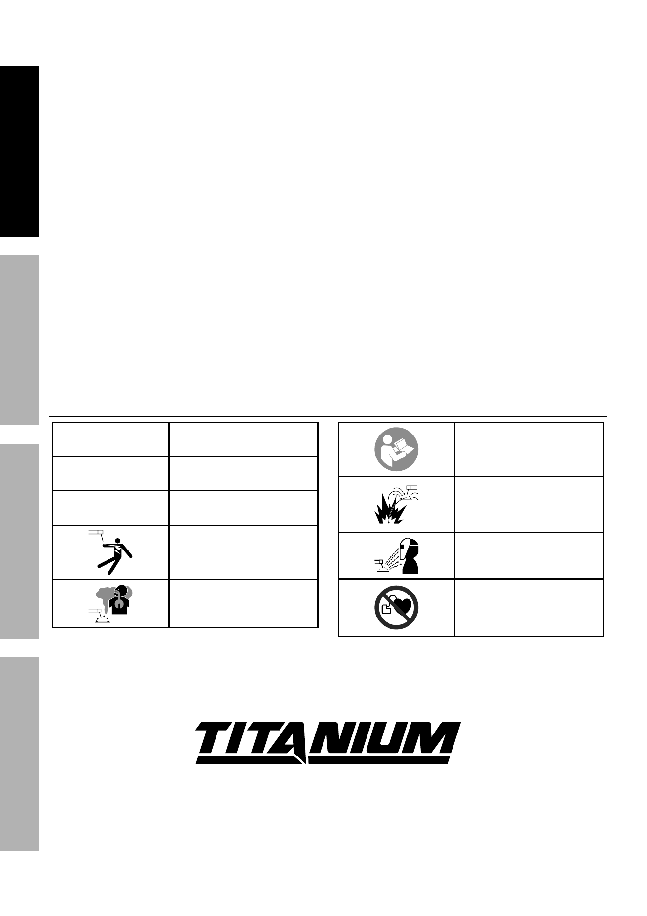
Symbology
Vac
Volts Alternating Current
a
Amperes
OcV
Open Circuit Voltage
Electric Shock Hazard.
Do not touch energized parts.
Inhalation Hazard.
Keep head out of fumes
and use proper ventilation.
Read manual before
setup and/or use.
Fire Hazard.
Keep flammable materials
away during cutting. Spatter
can cause accidental fires.
Arc Ray Hazard.
Wear welding helmet with
properly rated filter lens.
Pacemaker Hazard.
Cutting processes may
interfere with pacemakers.
Consult doctor before use.
tM
Page 5For technical questions, please call 1-800-444-3353.ITEM 56255
SaFetyOperatiOnMaintenance Setup
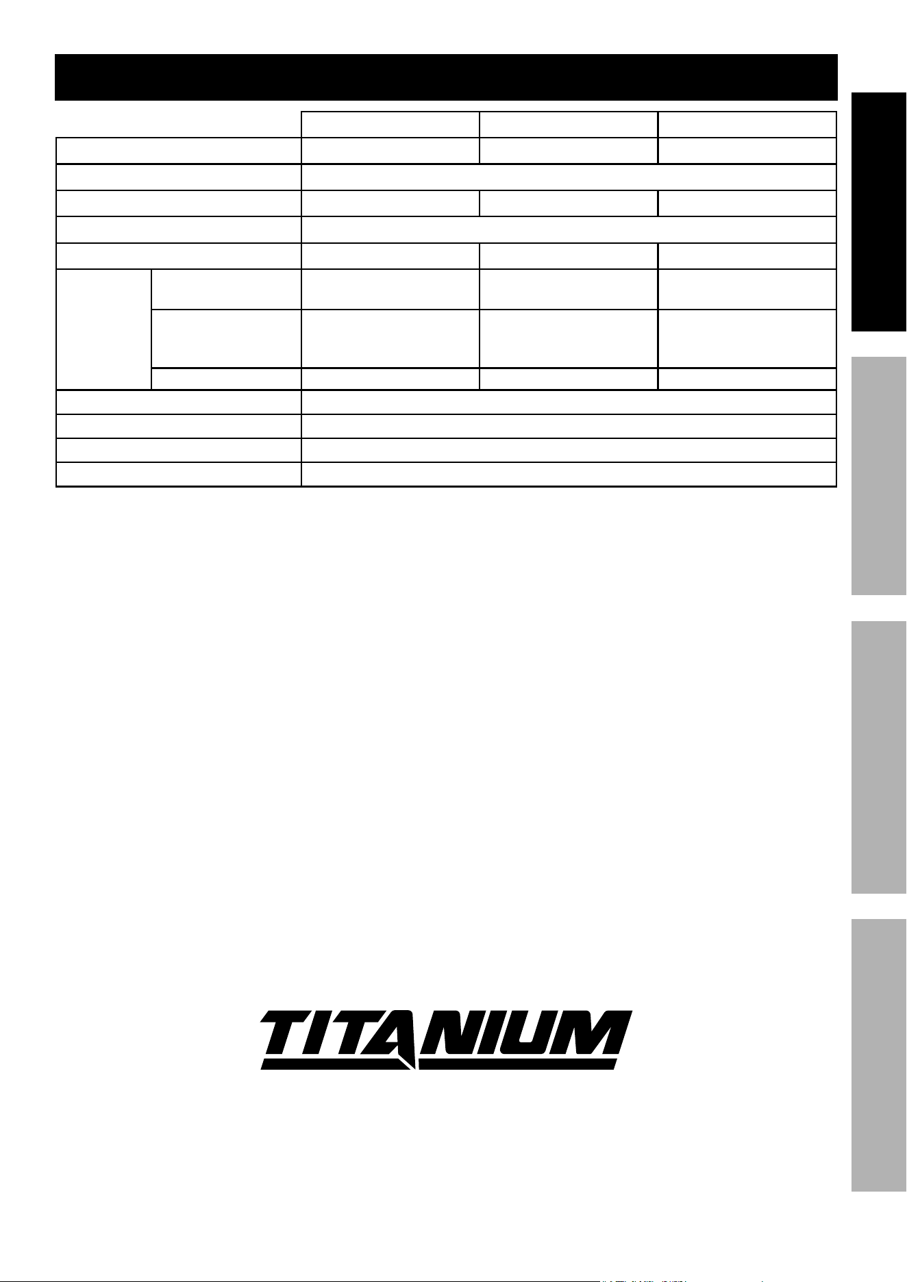
Specifications
120V / 15a circuit 120V / 20a circuit 240V
Rated Input 120 VAC / 60 Hz / 15A 120 VAC / 60 Hz / 20A 240VAC / 60Hz / 30A
Open Circuit Voltage (OCV) 315V
Output Range 15‑16A 15‑20A 15‑45A
Rated Output Voltage 140VDC
Rated Duty Cycle 35% @ 16A 35% @ 20A 50% @ 45A
Maximum
Cutting
Thickness
Mild Steel 1/8″ @ 11 IPM 1/4″ @ 11 IPM
5/8″ @ 15 IPM (Rated)
1″ @ 5 IPM (Severance)
Stainless Steel /
Galvanized Steel /
Aluminum
5/64″ 5/32″ 5/8″
Brass / Copper 5/64″ 1/8″ 15/32″
Arc Striking System 5 second pilot arc
Gas Type Clean, dry, oil‑free air or nitrogen gas
Air Requirements 4.2 CFM @ 80‑110 PSI
Air Inlet 1/4" – 18 NPT
tM
Page 6 For technical questions, please call 1-800-444-3353. ITEM 56255
SaFety OperatiOn MaintenanceSetup
Setup
read the entire iMpOrtant SaFety inFOrMatiOn section at the beginning of this
manual including all text under subheadings therein before set up or use of this product.
note: For additional information regarding the parts listed in the following pages,
refer to the Assembly Diagram near the end of this manual.
note: This Plasma Cutter may be shipped with a protective plug
covering the Air Inlet. Remove this plug before set up.
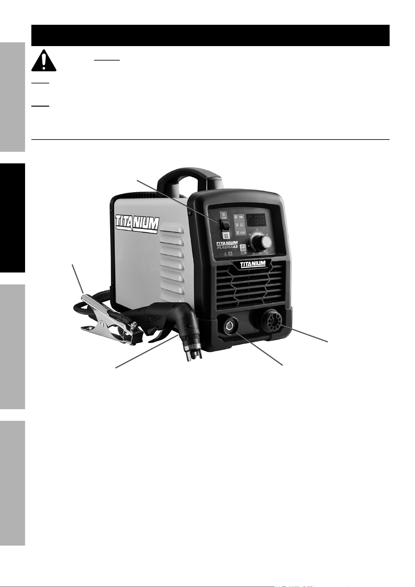
Functions
Ground
clamp cable
Socket
torch cable
Socket
Voltage
Switch
plasma
torch
Ground
clamp
Page 7For technical questions, please call 1-800-444-3353.ITEM 56255
SaFetyOperatiOnMaintenance Setup
power plug
1. A 6‑50P plug is wired into this item,
rated to 240 VAC and 45 A.
2. This item includes a 240V to 120V Plug
Adapter. The adapter and Voltage Switch
need to be changed at the same time
and must always match each other.
3. a different 230‑240 VAC receptacle may
be used, if it is rated to at least 30 amps.
If the receptacle is rated properly, a qualified
electrician can cut the plug off of this machine
and install a different appropriate 240 VAC plug.
air Supply
tO preVent SeriOuS inJury anD DeatH FrOM eXpLOSiOn:
use only clean, dry, regulated, oil-free, compressed air or nitrogen gas with this plasma cutter.
Do not use oxygen, acetylene, carbon dioxide, combustible gases,
or any other bottled gas as a power source for this plasma cutter.
1. Use a compressor that is capable of
supplying 4.2 CFM @ 80‑110 PSI.
2. Incorporate a filter, regulator with pressure gauge,
dryer, in‑line shutoff valve, and quick coupler for
best service. an in-line shutoff ball valve is an
important safety device because it controls
the air supply even if the air hose is ruptured.
the shutoff valve should be a ball valve
because it can be closed quickly.
note: in humid locations, multiple dryers may need
to be incorporated to keep the air dry. MOiSture
in air SuppLy May cauSe SHOrteneD
cOMpOnent LiFe anD pOOr cut QuaLity.
note: Do not use an oiler system with this
plasma cutter. the oil will mix with the air
being propelled, causing poor results.
3. Attach an air hose to the compressor’s air outlet.
Connect the air hose to the Air Inlet on the back
of the Plasma Cutter. Other components, such
as a coupler plug and quick coupler, will make
operation more efficient, but are not required.
note: Air flow, and therefore Plasma Cutter
performance, can be hindered by undersized air
supply components.
The air hose must be long enough to reach
the work area with enough extra length to
allow free movement while working.
Setting compressor's air pressure
1. Set the Plasma Cutter’s power Switch
to the OFF position.
2. Turn on the air compressor according to
the manufacturer’s directions and allow it
to build up pressure until it cycles off.
3. Verify that the air compressor’s output air
pressure regulator is between 80-110 pSi.
4. Inspect the air connections for leaks.
Repair any leaks found.
Page 8 For technical questions, please call 1-800-444-3353. ITEM 56255
SaFety OperatiOn MaintenanceSetup
Operation
read the entire iMpOrtant SaFety inFOrMatiOn section at the beginning of this manual
including all text under subheadings therein before set up or use of this product.
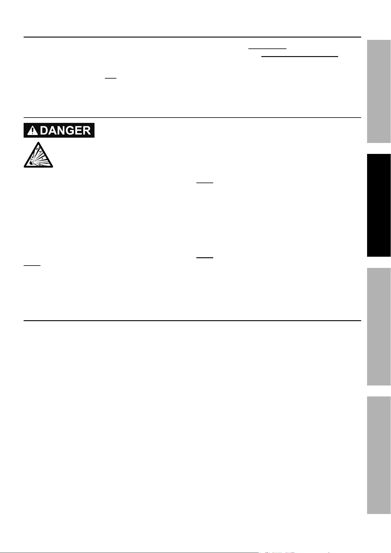
controls and indicators
6
1
2
3
4
5
7
9
10
8
1. Output current Knob
Turn the Output Current Knob to the desired
current (15 to 45 amps). Lower currents reduce
circuit breaker tripping. Adjust as needed after
test cuts.
Thicker material will use greater amperage.
Thinner material will use lower amperage.
2. Digital amp Meter
Shows actual cutting current,
which will vary during operation.
3. power On Light
Green light will be on when power is on.
4. thermal Overload Light
Yellow light will be on if the Plasma Cutter
shuts down due to overload. Stop using the
Plasma Cutter while leaving the Power Switch ON
to allow the cooling fan to operate.
The light will turn off automatically when the
Plasma Cutter cools down.
Continue use while paying attention to
Duty Cycle discussed on page 10.
5. cutting Light
Red light will be on during cutting operation.
6. Voltage Switch & Voltage Sensor indicators
Up is 240V, down is 120V.
iMpOrtant: change the Voltage Switch to the
voltage of the outlet you will use. If using 120VAC,
connect the included adapter to the end of the Power
Cord. If using 240VAC, do not use the adapter. Plug
the Power Cord into a properly grounded and rated
receptacle that matches the plug and selected voltage.
7. power Switch. Turn unit on and off.
8. power cord
9. air inlet
10. Dryer
tM

Page 9For technical questions, please call 1-800-444-3353.ITEM 56255
SaFetyOperatiOnMaintenance Setup
preparation and Work area
WarninG! prevent eye serious injury and
burns. Wearing personal protective equipment
reduces the risk of serious injury.
1. Wear an ANSI‑approved welding helmet featuring
at least a number 10 shade lens rating.
Leather leggings, fire resistant shoes or
boots should be worn when using this
product. Do not wear pants with cuffs, shirts
with open pockets, or any clothing that can
catch and hold molten metal or sparks.
Keep clothing free of grease, oil, solvents,
or any flammable substances. Wear dry,
insulating gloves and protective clothing.
Wear an approved head covering to protect the
head and neck. Use aprons, cape, sleeves,
shoulder covers, and bibs designed and
approved for welding and cutting procedures.
Wear fire resistant ear plugs or ear
muffs to keep sparks out of ears.
Do not breathe arc fumes. Use
natural or forced air ventilation and wear
a NIOSH‑approved respirator.
WarninG! tO preVent SeriOuS inJury:
prevent accidental fires. remove any
combustible material from the work area.
2. Remove or make safe all combustible
materials for a radius of 35 feet (10 meters)
around the work area. Use a fire resistant
material to cover or block all open doorways,
windows, cracks, and other openings.
Enclose the work area with portable fire
resistant screens. Protect combustible
walls, ceilings, floors, etc., from sparks
and heat with fire resistant covers.
3. The floor and surrounding area must not
be flammable. A clean concrete floor is
recommended.
The cutting process will eject
molten metal slag onto the floor, and it will
scatter for 8‑10 feet or more in all directions.
4. Keep multiple aBc-type fire
extinguishers near work area.
5. Place the Plasma Cutter on a sturdy, level surface
at least six feet from the work area.
Allow at least 18" around all sides of
the Plasma Cutter for air flow.
6. Put the workpiece on a sturdy metal work
table that is open below the cutting area.
Molten slag will be blown through the
workpiece, and must be able to fall away freely.
Mount the workpiece to be cut to the work table so
that the cutting debris falls to the concrete floor.
7. Set up Air Supply according to page 7.
8. Verify that the Power Switch is in the OFF
position, then plug the Plasma Cutter:
a. into an appropriate 240 VAC outlet rated
to at least 30 amps to limit nuisance
circuit breaker tripping. ensure that
the Voltage Switch is set to 240V.
b. into an appropriate 120VAC outlet, connecting the
included adapter to the end of the Power Cord.
ensure that the Voltage Switch is set to 120V.
9. pLaSMa cuttinG tipS:
Using a Plasma Cutter is a skill that
requires time and effort to do well.
a. Practice striking and maintaining an arc on
scrap work pieces before beginning work.
This will help determine the best settings for
the Plasma Cutter for the material at hand.
b. All metals that conduct electricity can
be cut, see Maximum cutting thickness
on page 5 for thickness capabilities.
Very thin or very thick metals are
more difficult to cut cleanly.
c. Generally start with a mid‑range amperage
setting and adjust up or down from there.
Increased amperage will increase cutting heat.
This is needed with thicker and harder metals.
However, increased amperage will
reduce Duty Cycle time. (See page10.)
d. Move the Torch more slowly for thicker and
harder metals, and more quickly for thin or soft
metals. Keep the Torch moving while cutting.
thicker Material
High amps
More air pressure
thinner Material
Low amps
Less air pressure
Page 10 For technical questions, please call 1-800-444-3353. ITEM 56255
SaFety OperatiOn MaintenanceSetup
Basic Operation
pLaSMa arc can cauSe SeriOuS inJury,
incLuDinG SeVere cutS, BurnS, perManent eye DaMaGe anD BLinDneSS!
Once the trigger is squeezed, the arc will ignite iMMeDiateLy.
the torch does not need to contact the workpiece before the pilot arc ignites.
Do not look at the plasma arc without an anSi-approved welding helmet featuring at
least a number 10 shade lens rating.
1. BeFOre eacH uSe, inspect the general
condition of the Plasma Cutter. Check for:
• loose hardware
• damaged cord/electrical wiring
• cooling fan operation
• cracked or broken parts
• any other condition that may
affect its safe operation.
Have a qualified technician correct
any problems before operation.
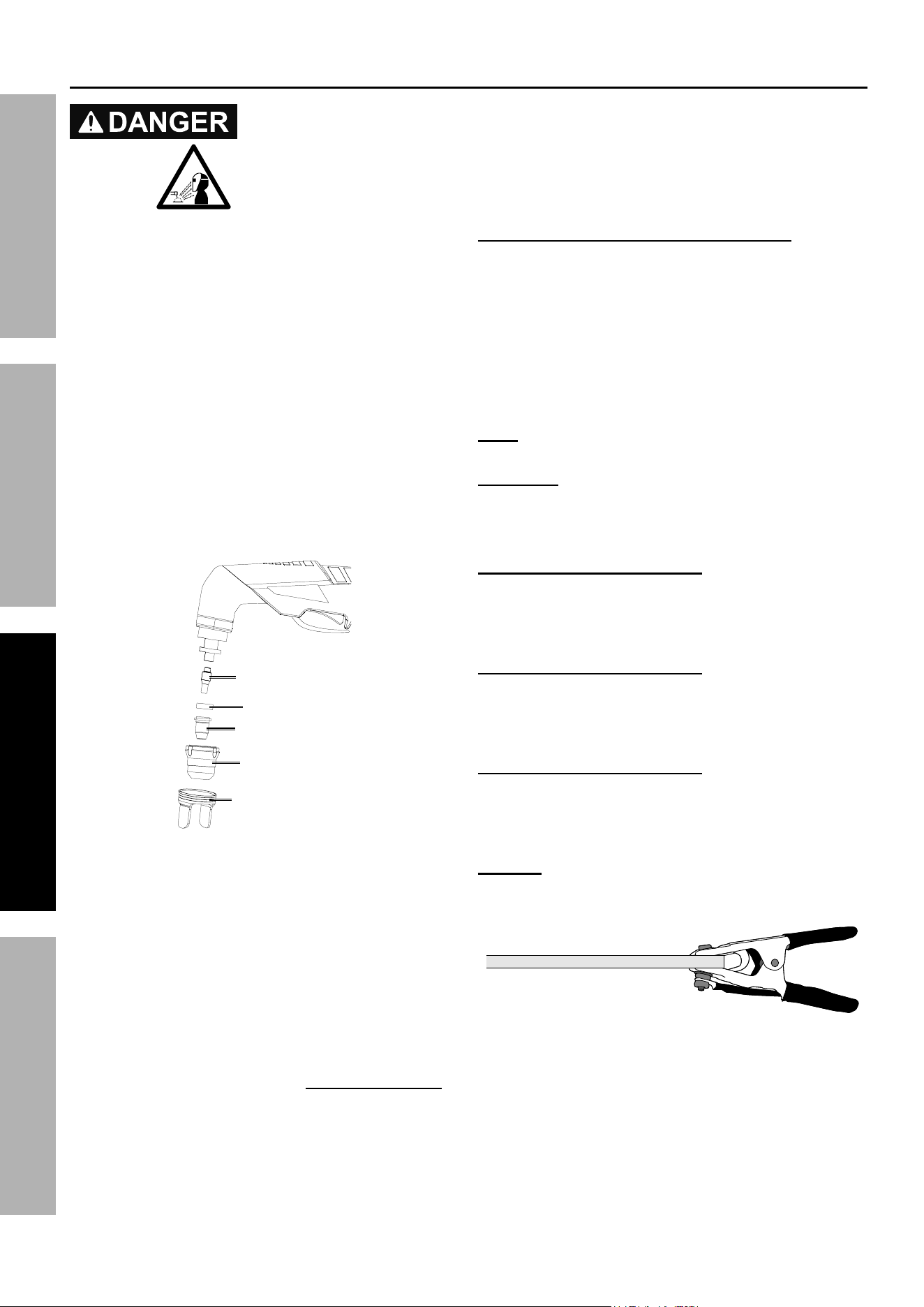
2. Maintain tOrcH cOMpOnentS
BeFOre eVery uSe anD aFter
eVery HOur OF OperatiOn.
Disconnect power cord and make sure
Torch is completely cool, then:
a. Disassemble Torch.
electrode
Swirl ring
cutting tip
retaining cup
Drag cup
b. Inspect the cutting tip.
replace if interior is damaged, or
if opening is enlarged or gouged.
Clean inside as needed with steel wool,
(remove any pieces of steel wool afterwards).
c. Inspect the electrode. replace if pitted
1/16" or more or if misshapen.
iMMeDiateLy repLace WOrn cOMpOnentS.
d. Make sure all other internal torch components
are undamaged, clean, and free of debris.
e. nOtice: assemble electrode just snug using
the included wrench, but do not overtighten.
f. Insert the Swirl Ring and
Cutting Tip into the torch.
g. Assemble the Retaining Cup tightly.
DO nOt uSe WitH WOrn cOMpOnentS.
uSinG WOrn cOMpOnentS WiLL VOiD tHe
Warranty anD DaMaGe tHe pLaSMa cutter.
3. Ensure switch is properly set to the voltage range
you will use and connect power cord (and adapter
if using 120VAC). Attach the Drag Cup (cutting
guide) to the end of the Torch so that its guides
are parallel to the cutting path. It drags on the
workpiece to keep the distance from the Torch to
the workpiece constant for longer Cutting Tip life.
note: For clarity, the Drag Cup is not
shown in the following illustrations.
Duty cycle
Duty Cycle is the equipment specification which
defines the number of minutes within a 10 minute
period that a piece of equipment can safely operate.
When using a 120V 15A circuit, this Plasma Cutter
has a 35% duty cycle at 16 amps, which
means that it may be used only 3.5 minutes
at 16 amps out of any 10 minute period, and
must be rested the remaining 6.5 minutes.
When using a 120V 20A circuit, this Plasma
Cutter has a 35% duty cycle at 20 amps, which
means that it may be used only 3.5 minutes
at 20 amps out of any 10 minute period, and
must be rested the remaining 6.5 minutes.
When using a 240V 30A circuit, this Plasma
Cutter has a 50% duty cycle at 45 amps,
which means that it may be used only 5 minutes
at 45 amps out of any 10 minute period, and
must be rested the remaining 5 minutes.
nOtice: Failure to follow the duty cycle limitations
of this Plasma Cutter can easily damage this
equipment, and will void the warranty.
4. Securely attach the Ground Clamp to a part
of the workpiece or metal work table that is
clean, dry, and free from paint, oil, or dirt.
Clamp as close as possible to the planned
cut without exposing the Clamp to damage.
5. When everything is in place for cutting,
set the Power Switch to the On position.
The green Power Light will illuminate,
but the Torch is not yet energized.
Page 11For technical questions, please call 1-800-444-3353.ITEM 56255
SaFetyOperatiOnMaintenance Setup
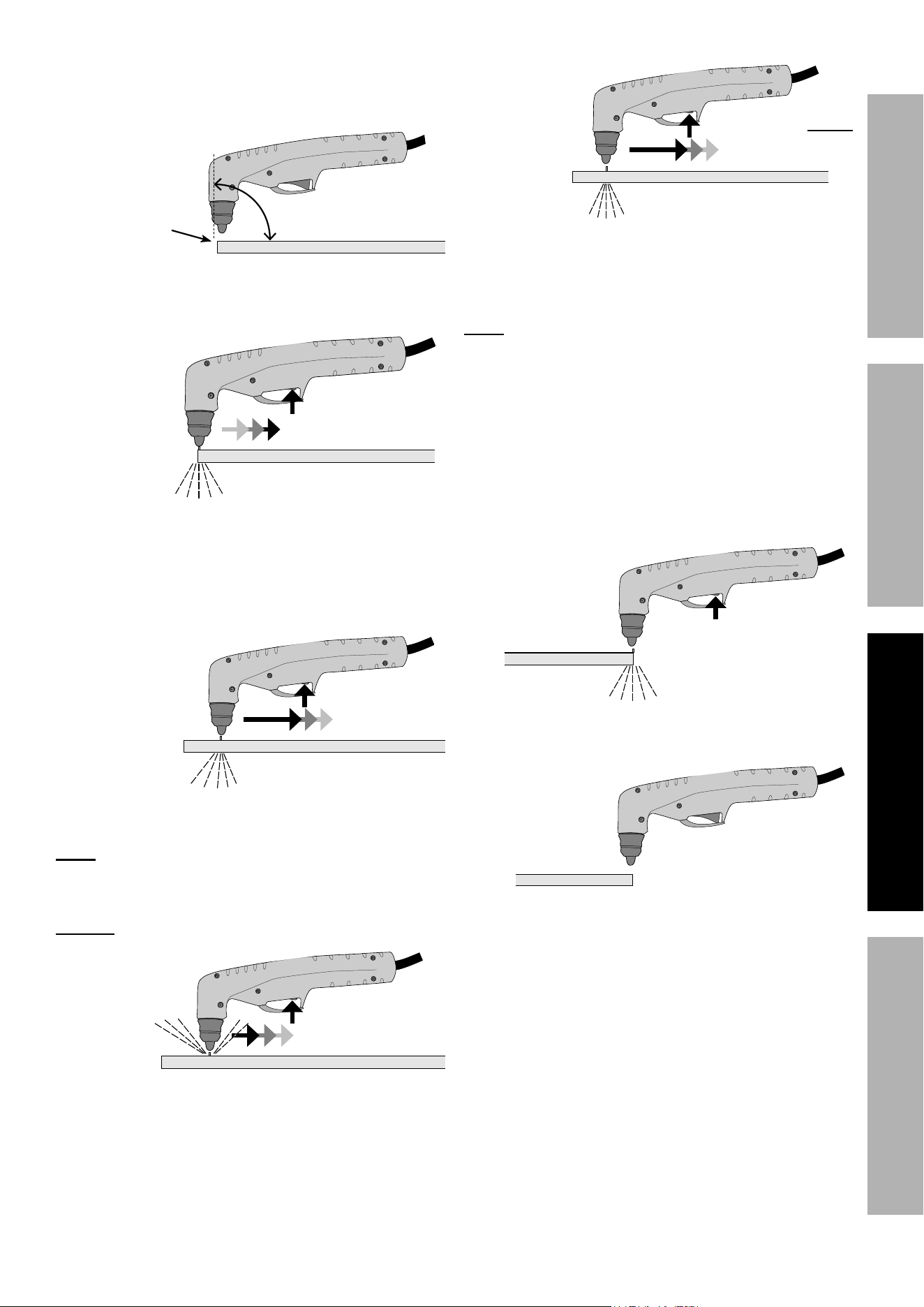
6. Orient yourself to one side of the cutting
area, and move the Welding Helmet
(sold separately) over your eyes.
Keep
1/16" distance
from workpiece
90º
7. Position Torch near workpiece at start of cut.
Keep Cutting Tip at a 90º angle to workpiece,
and at 1/16" distance from workpiece.
8. Do not squeeze trigger until torch
is in position to start cutting.
Starting at the edge of the workpiece, squeeze
and hold the Trigger to strike the pilot arc.
When the arc ignites, start slowly moving
the Torch along your cut line.
9. Slowly move the Torch along the cutting
line with the Cutting Tip trailing.
note: Keep the Torch Cutting Tip pointed
straight (90º) into the workpiece 1/16" from the
surface. Consistent workpiece distance and
cutting speed are critical. Sparks should pass
through the workpiece at a slight angle.
SLOW DOWn
if sparks do not pass
through workpiece
10. If sparks start shooting up from the workpiece
instead of passing through, the Torch is being
moved too quickly so the cut is not being
made completely. Move the Torch along the
workpiece more slowly to cut completely.
SpeeD up
if sparks pass straight
down through bottom
of workpiece
11. If sparks pass straight down through bottom of
workpiece instead of at a slight angle, the Torch
is being moved too slowly. This could cause the
arc to extinguish. Move the Torch a little faster.
note: if the plasma cutter suddenly shuts off, check:
a. torch distance from workpiece.
b. poor workpiece grounding.
c. dirty/painted workpiece.
d. circuit Breaker & power Switch tripping.
e. thermal Overload tripping.
(See number 4 on page 8.)
12. Pause briefly at end of cut.
13. Release the Trigger. The air will continue to come
out of the Torch for a few seconds once the Trigger
is released to cool off the Torch components.
14. When finished cutting:
a. Lift the Torch from the workpiece and set
down on a cool part of the metal work table.
b. Wait 10 minutes for the Plasma Cutter
to cool down with the Power Switch On
so the fan continues to operate.
c. Press the Power Switch to the OFF position.
d. Turn the air supply off and disconnect air lines.
e. Unplug the Power Cord from the electrical outlet.

Page 12 For technical questions, please call 1-800-444-3353. ITEM 56255
SaFety OperatiOn MaintenanceSetup
Maintenance instructions
procedures not specifically explained in this manual
must be performed only by a qualified technician.
tO preVent SeriOuS inJury FrOM acciDentaL OperatiOn Or eLectric SHOcK:
Make sure the power Switch of the plasma cutter is in its "OFF" position and that the plasma cutter is
unplugged from the electrical outlet before performing any inspection, maintenance, or cleaning procedures.
tO preVent SeriOuS inJury FrOM pLaSMa cutter FaiLure:
Do not use damaged equipment. if abnormal noise, vibration, or leaking
air occurs, have the problem corrected before further use.
cleaning and Maintenance
note: These procedures are in addition to the regular checks and maintenance
explained as part of the regular operation of the air‑operated tool.
1. BeFOre eacH uSe, disassemble torch,
inspect and replace worn components,
then reassemble torch tightly according
to number 2 on page 10.
2. Daily - air Supply Maintenance:
Every day, maintain the air supply according
to the component manufacturers' instructions.
Drain the dryer regularly.
Performing routine air supply maintenance
will allow the tool to operate more safely
and will also reduce wear on the tool.
3. periODicaLLy, blow the dust from the
cooling vents with compressed air.
4. If the unit repeatedly shuts down
from thermal overload, stop all use.
Have the Plasma Cutter inspected and
repaired by a qualified service technician.
5. Opening the plasma cutter will void the
warranty, and may result in damage to
equipment or possible personal injury.
DO nOt Open tHe HOuSinG.
Any repairs must be completed
by a qualified technician.
6. Store the Plasma Cutter and accessories in a
clean and dry location out of reach of children.
7. WarninG! tO preVent SeriOuS inJury:
if the supply cords of this plasma cutter
are damaged, they must be replaced only
by a qualified service technician.

Page 13For technical questions, please call 1-800-444-3353.ITEM 56255
SaFetyOperatiOnMaintenance Setup
Fault code List
code Description cause and Solution
F01 Overheated
1. The machine has reached its duty cycle limit.
2. Allow the machine to cool down. Keep the machine
plugged in and turned on to allow the fan to continue to run.
Additionally, check for any obstructions blocking air flow
into the machine and ensure proper clearance between
any obstacles and the vents on all sides of the machine.
F02
Incorrect input
voltage
1. The input voltage is too high or too low.
2. Check the service voltage at the outlet and
ensure it is within the specified range.
F03
Shield cup loose
or missing
Install the shield cup properly and
ensure it is tightened properly.
F04
Insufficient input
air pressure
1. The input compressed air/gas pressure
is lower than the specified range.
2. Check the air inlet connection and ensure the air pressure
supplied meets the minimum criteria of machine.
F05
Torch triggered
before machine
is turned on
1. The torch trigger is stuck or is triggered
when turning on the machine.
2. Turn OFF the machine, and ensure the torch trigger is reset.
F06
Electrode and
nozzle stuck
together
Disassemble the torch consumables, check
electrode and nozzle condition and replace
as necessary, and reset them in place.
F07
Electrode or
nozzle failed
to reset
1. Disassemble the torch consumables, check
electrode and nozzle condition and replace
as necessary, and reset them in place.
2. Additionally, use clean, compressed air to
remove any debris within torch head.

Page 14 For technical questions, please call 1-800-444-3353. ITEM 56255
SaFety OperatiOn MaintenanceSetup
troubleshooting
iMpOrtant!
Be certain to shut off the plasma cutter, and disconnect it from power and air before adjusting, cleaning, or
repairing the unit. a technician should discharge all capacitors before performing any internal procedures.
Fan runS WHen SWitcHeD On But arc WiLL nOt iGnite
if the steps above do not solve the problem or if the repairs involved are too
complex, contact a qualified technician.
Verify that air supply is
between 80-110 pSi.
air preSSure
tOO HiGH
air preSSure
tOO LOW
Verify that the compressor
is delivering at least
4.2 cFM @ 80-110 pSi.
air preSSure
cOrrect
check that the grounding point and
the metal being cut are both clean,
dry, and free from paint, oil, or dirt.
these sections need to conduct
electricity efficiently.
use a wire wheel brush or sander
(not included) to thoroughly
clean both the grounding point
and the area that will be cut.
if any cleaners are used, allow them
to dry thoroughly before continuing.
Dirty Or
cOateD MetaL
MetaL iS cLean in
BOtH areaS
torch isn’t maintaining contact with the workpiece.
a. Maintain a 1/16" distance
from workpiece at all times.
b. Disassemble torch, inspect and replace worn
components, then reassemble torch tightly
according to number 2 on page 10.
c. torch is moving too slowly across the metal
and cutting the material from underneath,
breaking contact. Move torch more quickly.

Page 15For technical questions, please call 1-800-444-3353.ITEM 56255
SaFetyOperatiOnMaintenance Setup
troubleshooting (continued)
air pressure too high or too low.
check the air pressure setting on both
the compressor and the plasma cutter.
Verify that compressor's
air pressure regulator
is between 80-110 pSi.
air preSSure
tOO HiGH
air preSSure
tOO LOW
a. Verify cutter's air
pressure at the torch.
use a wire wheel brush or sander
(not included) to thoroughly
clean both the grounding point
and the area that will be cut.
if any cleaners are used, allow them
to dry thoroughly before continuing.
Dirty Or
cOateD MetaL
MetaL iS cLean in
BOtH areaS
torch isn’t maintaining contact with the workpiece.
a. Maintain a 1/16" distance
from workpiece at all times.
b. Disassemble torch, inspect and replace worn
components, then reassemble torch tightly
according to number 2 on page 10.
c. torch is moving too slowly across the metal
and cutting the material from underneath,
breaking contact. Move torch more quickly.
air preSSure
cOrrect
iMpOrtant!
Be certain to shut off the plasma cutter, and disconnect it from power and air before adjusting, cleaning, or
repairing the unit. a technician should discharge all capacitors before performing any internal procedures.
if the steps above do not solve the problem or if the repairs involved are too
complex, contact a qualified technician.
arc iGniteS FOr SeVeraL SecOnDS But tHen GOeS Out
check that the grounding point and
the metal being cut are both clean,
dry, and free from paint, oil, or dirt.
these sections need to conduct
electricity efficiently.

Page 16 For technical questions, please call 1-800-444-3353. ITEM 56255
SaFety OperatiOn MaintenanceSetup
troubleshooting (continued)
iMpOrtant!
Be certain to shut off the plasma cutter, and disconnect it from power and air before adjusting, cleaning, or
repairing the unit. a technician should discharge all capacitors before performing any internal procedures.
if the steps above do not solve the problem or if the repairs involved are too
complex, contact a qualified technician.
take note of the setting required
for this metal thickness.
cut GOeS OnLy partiaLLy tHrOuGH tHe WOrKpiece
turn up the Output current
Knob and try again at a
slower torch travel speed.
Material being cut is too thick.
See Maximum cutting thickness on page 5.
use a more
powerful
plasma cutter.
WitHin tHicKneSS
ranGe
tOO tHicK
air preSSure
cOrrect
prOBLeM
cOrrecteD
Disassemble torch, inspect and
replace worn components, then
reassemble torch tightly according
to number 2 on page 10.
Disassemble torch, inspect and
replace worn components, then
reassemble torch tightly according
to number 2 on page 10.
tOrcH in GOOD
cOnDitiOn
DaMaGeD
cOMpOnentS FOunD
Cut at a slower pace — the arc
may not have enough time to
cut through the workpiece.
See Specifications on page 5.

Page 17For technical questions, please call 1-800-444-3353.ITEM 56255
SaFetyOperatiOnMaintenance Setup
troubleshooting (continued)
iMpOrtant!
Be certain to shut off the plasma cutter, and disconnect it from power and air before adjusting, cleaning, or
repairing the unit. a technician should discharge all capacitors before performing any internal procedures.
if the steps above do not solve the problem or if the repairs involved are too
complex, contact a qualified technician.
current set too high;
cut at lowest setting possible
for the metal being cut.
FaSt cuttinG tip Wear Or eXceSSiVe SLaG FOrMatiOn
take into account the thickness
and type of metal to be cut before
starting. thinner materials
require lower amp settings.
prOBLeMS
reDuceD
Disassemble and inspect
torch according to
number 2 on page 10.
replace worn components,
then reassemble torch
tightly according to
number 2 on page 10.
tOrcH in GOOD
cOnDitiOn
DaMaGeD
cOMpOnentS FOunD
air supply pressure may be inadequate:
a. Verify that the compressor is delivering
at least 4.2 CFM @ 80 – 110 PSI.
additional factors:
a. Maintain a 1/16" distance from workpiece at all times.
b. Move torch at proper rate. See
Specifications on page 5.
c. compare workpiece thickness to Maximum
cutting thickness on page 5.
these two problems have similar causes
and will often appear simultaneously.
the same diagnostic procedures
and remedies apply to both.
prOBLeMS perSiSt at
LOWeSt practicaL SettinG
Page 18 For technical questions, please call 1-800-444-3353. ITEM 56255
SaFety OperatiOn MaintenanceSetup
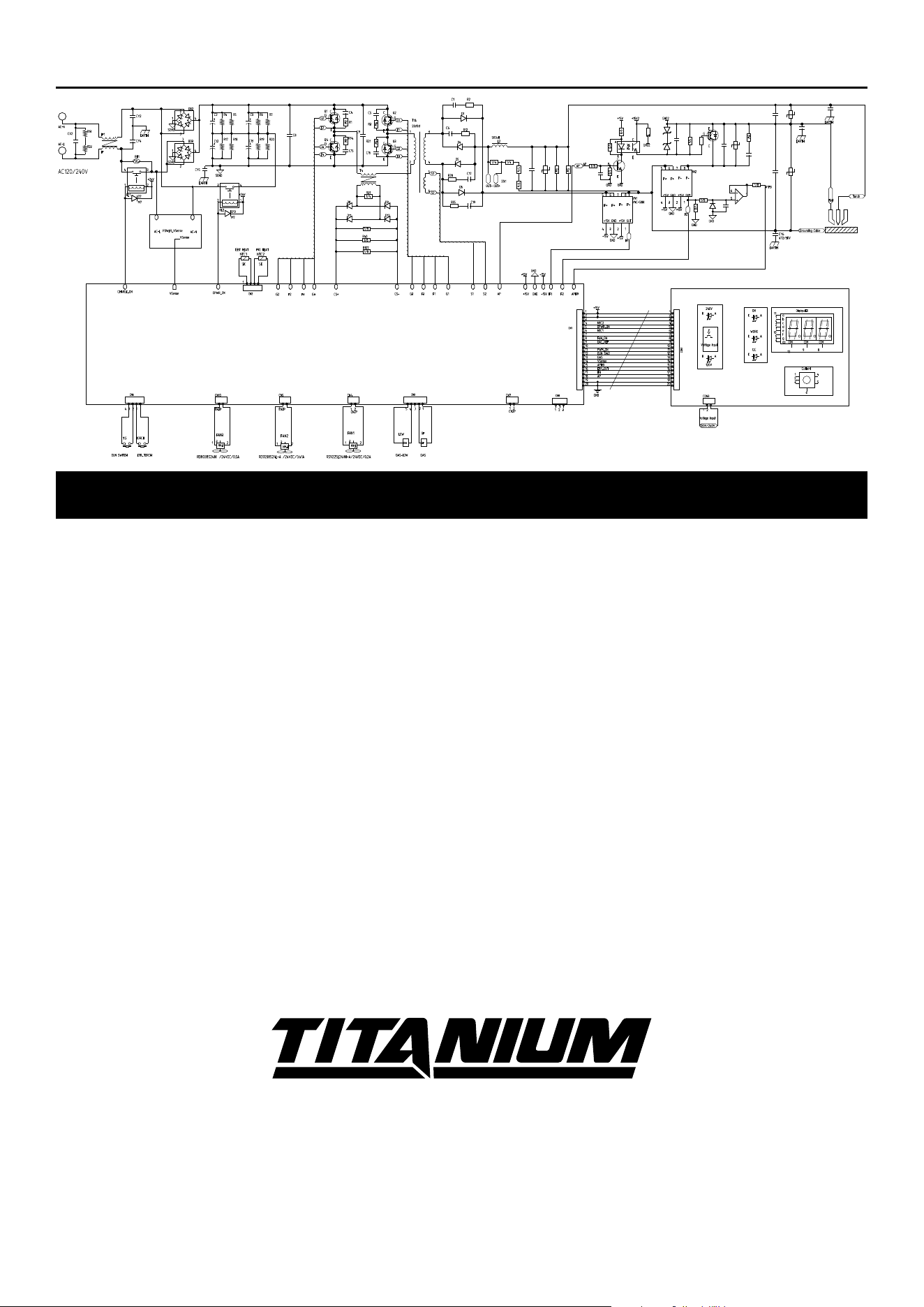
pLeaSe reaD tHe FOLLOWinG careFuLLy
THE MANUFACTURER AND/OR DISTRIBUTOR HAS PROVIDED THE CIRCUIT DIAGRAM, PARTS LIST AND
ASSEMBLY DIAGRAM IN THIS MANUAL AS A REFERENCE TOOL ONLY. NEITHER THE MANUFACTURER
OR DISTRIBUTOR MAKES ANY REPRESENTATION OR WARRANTY OF ANY KIND TO THE BUYER THAT HE
OR SHE IS QUALIFIED TO MAKE ANY REPAIRS TO THE PRODUCT, OR THAT HE OR SHE IS QUALIFIED
TO REPLACE ANY PARTS OF THE PRODUCT. IN FACT, THE MANUFACTURER AND/OR DISTRIBUTOR
EXPRESSLY STATES THAT ALL REPAIRS AND PARTS REPLACEMENTS SHOULD BE UNDERTAKEN BY
CERTIFIED AND LICENSED TECHNICIANS, AND NOT BY THE BUYER. THE BUYER ASSUMES ALL RISK
AND LIABILITY ARISING OUT OF HIS OR HER REPAIRS TO THE ORIGINAL PRODUCT OR REPLACEMENT
PARTS THERETO, OR ARISING OUT OF HIS OR HER INSTALLATION OF REPLACEMENT PARTS THERETO.
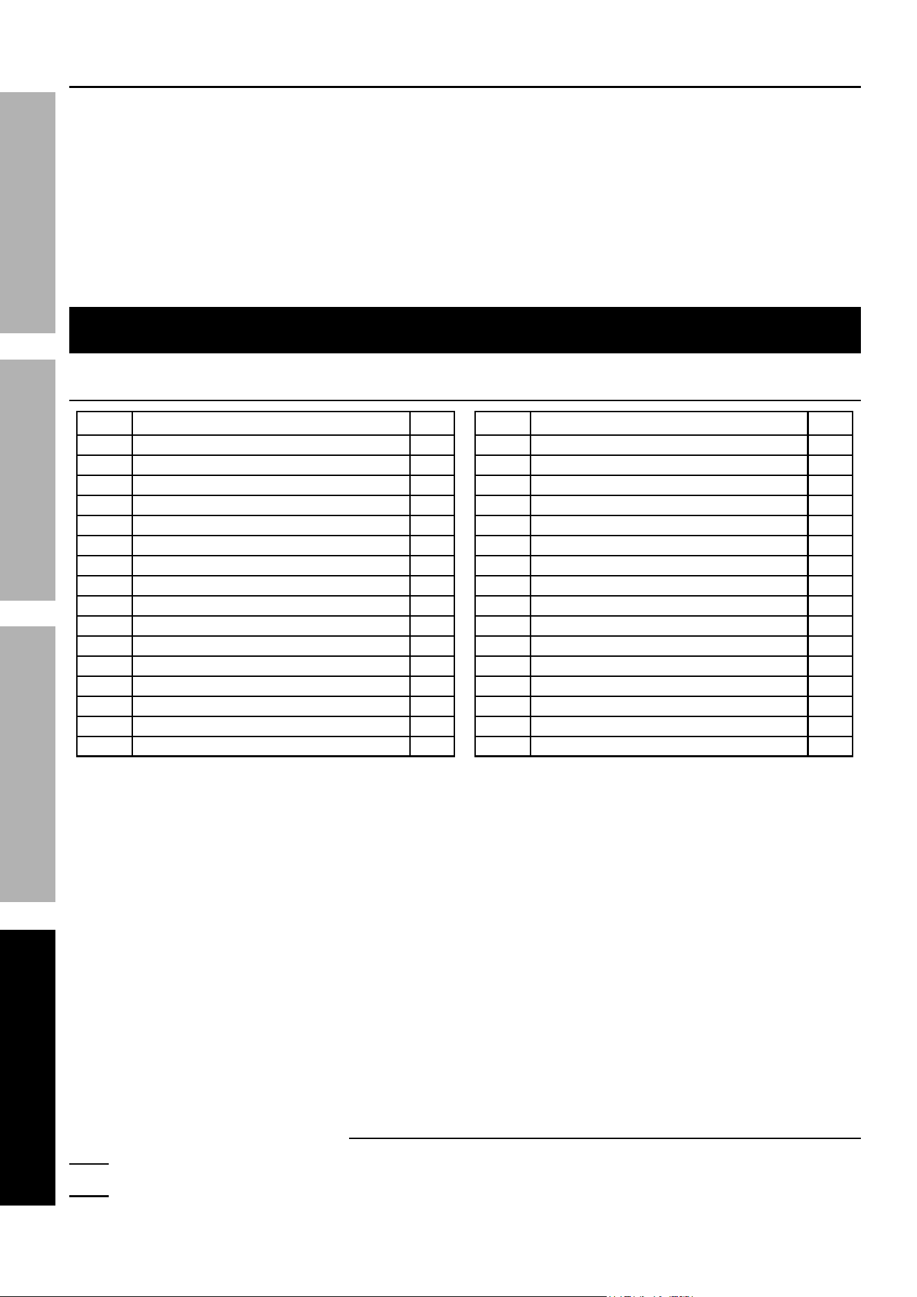
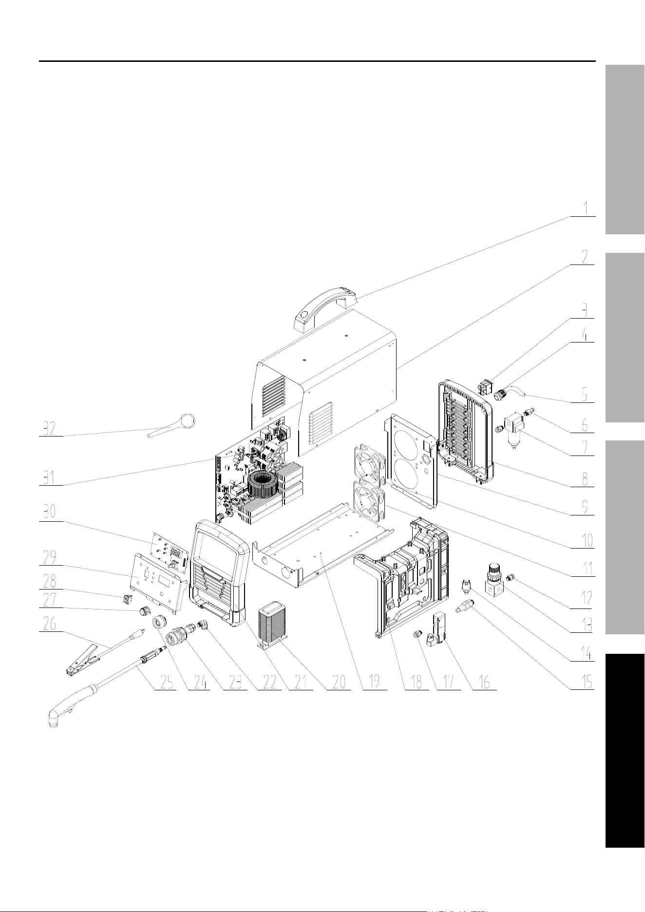
parts List and Diagram
parts List
part Description Qty
1 Handle
1
2 Enclosure
1
3 Power Switch
1
4 Power Cord Clamp
1
5 Power Cord
1
6 Gas Inlet
1
7 Dryer
1
8 Back Panel
1
9 Back Plate
1
10 Fan 2
1
11 Fan 1
1
12 Gas Connector
2
13 Regulator
1
14 Pressure Switch
1
15 Gas Connector
1
16 Gas Valve
1
part Description Qty
17 Gas Connector
1
18 Ventilation Chamber
1
19 Bottom Plate
1
20 Inductance Assembly
1
21 Front Panel
1
22 L‑Type Gas Connector
1
23 Torch Socket
1
24 Positive Socket
1
25 Plasma Torch
1
26 Ground Cable
1
27 Knob
1
28 Voltage Selection Switch
1
29 Front Panel
1
30 Front PCB
1
31 Main PCB
1
32 Wrench
1
record product’s Serial number Here:
note: if product has no serial number, record month and year of purchase instead.
note: Some parts are listed and shown for illustration purposes only, and are not available
individually as replacement parts. Specify UPC 193175511669 when ordering parts.
Page 19For technical questions, please call 1-800-444-3353.ITEM 56255
SaFetyOperatiOnMaintenance Setup
assembly Diagram
26677 agoura road • calabasas, ca 91302 • 1-800-444-3353
tM
Wiring Diagram
Main PCB
Display PCB
Limited 90 Day Warranty
Harbor Freight Tools Co. makes every effort to assure that its products meet high quality and durability standards,
and warrants to the original purchaser that this product is free from defects in materials and workmanship for the
period of 90 days from the date of purchase. This warranty does not apply to damage due directly or indirectly,
to misuse, abuse, negligence or accidents, repairs or alterations outside our facilities, criminal activity, improper
installation, normal wear and tear, or to lack of maintenance. We shall in no event be liable for death, injuries
to persons or property, or for incidental, contingent, special or consequential damages arising from the use of
our product. Some states do not allow the exclusion or limitation of incidental or consequential damages, so the
above limitation of exclusion may not apply to you. THIS WARRANTY IS EXPRESSLY IN LIEU OF ALL OTHER
WARRANTIES, EXPRESS OR IMPLIED, INCLUDING THE WARRANTIES OF MERCHANTABILITY AND FITNESS.
To take advantage of this warranty, the product or part must be returned to us with transportation charges
prepaid. Proof of purchase date and an explanation of the complaint must accompany the merchandise.
If our inspection verifies the defect, we will either repair or replace the product at our election or we may
elect to refund the purchase price if we cannot readily and quickly provide you with a replacement. We will
return repaired products at our expense, but if we determine there is no defect, or that the defect resulted
from causes not within the scope of our warranty, then you must bear the cost of returning the product.
This warranty gives you specific legal rights and you may also have other rights which vary from state to state.