
Table of Contents
1. Introduction ..................................................................1
2. Unpacking ....................................................................2
2.1 Part list ............................................................... 2
2.2 View and Size .................................................... 2
3. Set up Guide .................................................................4
3.1 Rain Gauge Sensor Pre-Setup ........................... 4
3.2 Console power-up and connect with the
WH40/WH40H rain gauge ...................................... 5
3.2.1 Power up .................................................5
3.2.2 Connect with the WH40/WH40H .......... 6
3.3 Console Display .................................................7
3.4 Rain Gauge Sensor(WH40/WH40H) Mounting8
3.5 Best Practice for Wireless (RF) Communication8
3.6 Wireless Signal Strength Indicator .................. 10
3.7 Rainfall Grade Graph .......................................11
3.7.1 Rainfall Range Represented by Colors 11
3.7.2 Rainfall Data Represented ....................11
4. Button operations and Operating Different Modes ... 12
4.1 Button Operations ............................................12
4.2 Normal Mode ...................................................14
4.3 Setting Mode ....................................................15

4.4 Calibration Mode .............................................16
4.5 Rain History Mode .......................................... 17
4.6 MIN/MAX Mode .............................................18
4.7 Alarm/Alert Setting Mode ............................... 19
5. Factory Reset and Rain Gauge Sensor Registration ..21
5.1 Reset to Factory ............................................... 21
5.2 Rain Gauge Sensor Registration: .................... 21
6. Features ......................................................................22
7. Troubleshooting Guide .............................................. 23
8. Specifications .............................................................26
9. Warranty Information ................................................ 27
10. FCC .......................................................................... 28
11. Contact Us ................................................................31
11.1 After-sales Service ......................................... 31
11.2 Stay in Touch ................................................. 32

1
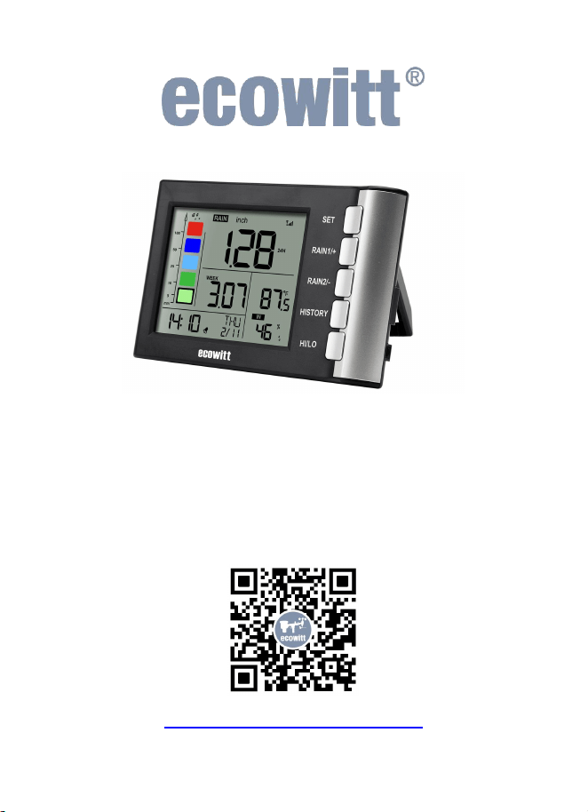
1. Introduction
Thanks for your purchasing of the WH5360 High
Precision Digital Rain Gauge with indoor temperature
and humidity sensors. To ensure the best product
performance, please read this manual and retain it for
future reference.
The WH5360 needs to be used with Ecowitt
WH40/WH40H Rainfall sensor to obtain outdoor rainfall
data. This device is not a standalone product.
General Terms Used in the Manual:
Weather Station: Includes the console and sensors (or
sensor array).
Receiver: Refers to the console.
Transmitter: Refers to the sensor or sensor array.
RF: Radio frequency. It refers to the ISM and SRD
SubG (Industrial, Scientific and Medical and Short
Range Devices frequency bands below 1 GHz) for
communicating between the console and its sensors. This
frequency is not the same as the 4G modem (LTE) or
Wi-Fi working frequencies (2.4 GHz, 5 GHz).)
ISM/SRD bands are kept separate from 4G frequencies
by national regulations to avoid interferences. Typical
ISM/SRD frequencies are 915MHz(Americas),
868MHz(Europe), 433MHz(worldwide), 920MHz
(Japan, Korea).
2
2. Unpacking
2.1 Part list
QTY
Item
1
WH5360 Display Console
1
User manual
Table 1: Package content
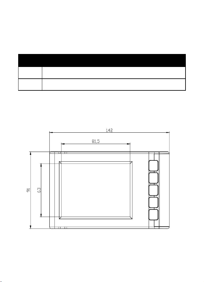
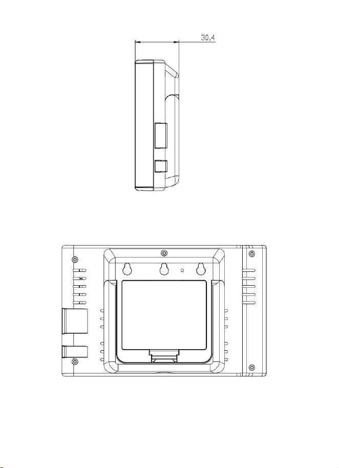
2.2 View and Size
Figure 1 Main view
3
Figure 2 Side view
Figure 3 Rear view

4
3. Set up Guide
Note:
We recommend assembling all components of the
WH40/WH40H rain gauge first. Place the
WH40/WH40H and the WH5360 console
together in one location to easily test
functionality. After testing, install the rain sensor
in its desired location.
However, that movement during and after
assembly can cause the rain sensor to falsely
detect rain. The rain total can be reset to 0 via the
console.
Attention:
Follow the suggested order for battery
installation (outdoor sensor first, then console).
Ensure batteries are installed with correct polarity
(+/-).
Only use new batteries.
3.1 Rain Gauge Sensor Pre-Setup
Pre-assemble the WH40/WH40H and install the batteries
to power it on, as instructed in the WH40/WH40H
Manual section 2.2—2.4. Then, place it next to the
WH5360 console.
5
3.2 Console power-up and connect with the
WH40/WH40H rain gauge
Note:
This connection does not require Wi-Fi.
Make sure that the RF frequency matches (the
frequency is different for various countries because
of regulations).
3.2.1 Power up
Insert three AA alkaline batteries (not included). Once
powered on, the unit will show the start-up display for
1 second (Figure 4), followed by a full-screen display
for 1 second (Figure 5), and then enter Normal Mode
Display(Figure 6).
Figure 4 Start-up Screen
6
Figure 5 Full-screen
Display
Figure 6 Normal Mode
Display
3.2.2 Connect with the WH40/WH40H
1. After powering up, the next step is to connect it
with the WH40/WH40H rain gauge, the console will
begin searching for the rain gauge sensor
(WH40/WH40H) data. This may take up to 3 minutes,
after which the data will be displayed on the console.
2. If the rainfall data does not appear on the
console, hold the RAIN1 / + and RAIN2 / -
buttons for 5 seconds. The device will register the
transmitter signal for 3 minutes.
7
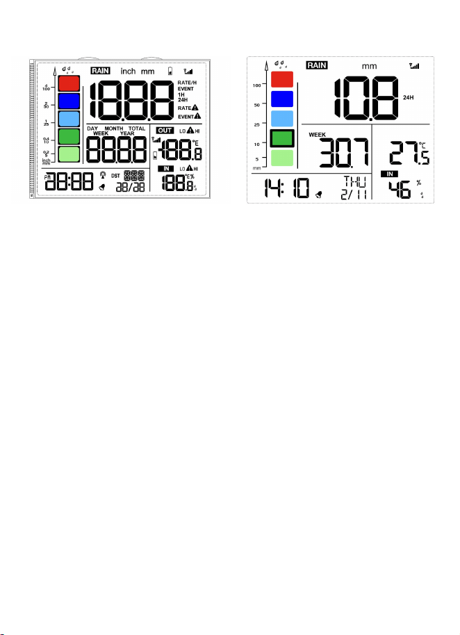
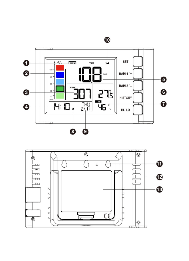
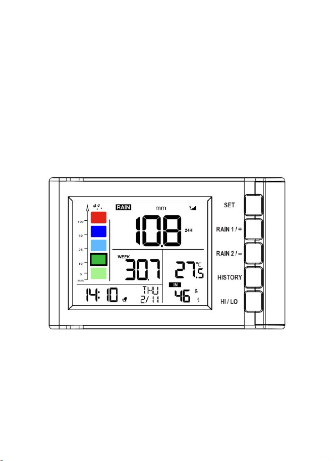
3.3 Console Display
Figure 7 Display Console Screen Layout
Figure 8 Rear Layout
8
1.Rainfall data display
8.Alarm icon
2.Rainfall grade graph
9.Date/Week
3.Rainfall of day/week/month/
year display
10.Signal icon
4.Time
11.Wall-mounted hole
5.Rain rate/event/1h/24h display
12.Table stand
6.Indoor temperature
13.Battery door
7.Indoor humidity
Table 2 Display console detailed items
3.4 Rain Gauge Sensor(WH40/WH40H)
Mounting
Place the rain sensor in the desired location. Refer to
WH40/WH40H User Manual Section 4 for details.
3.5 Best Practice for Wireless (RF)
Communication
Wireless (RF) communication is susceptible to
interference, distance, walls and metal barriers. We
recommend the following best practices for trouble free
wireless communication between both sensor and the
console:

9
Indoor/outdoor sensor placement: The sensor will have
the longest reach for its signal when mounted or hung
vertically. Avoid laying it down on a flat surface.
Electro-Magnetic Interference (EMI). Keep the console
several feet away from computer monitors and TVs.
Radio Frequency Interference (RFI). If you have other
devices operating on the same frequency band as your
indoor and/or outdoor sensors and experience
intermittent communication between sensor and console,
try turning off these other devices for troubleshooting
purposes. You may need to relocate the transmitters or
receivers to avoid the interference and establish reliable
communication. The frequencies used by the sensors are
one of (depending on your location): 433, 868, or 915
MHz (915 MHz for United States).
Line of Sight Rating. This device is rated at 300 feet line
of sight (under ideal circumstances; no interference,
barriers or walls), but in most real-world scenarios,
including a wall or two, you will be able to go about 100
feet.
Metal Barriers. Radio frequency will not pass through
metal barriers such as aluminum siding or metal wall
framing. If you have such metal barriers and experience
communication problems, you must change the
placement of sensor package and or console.
The following table shows different transmission media
and expected signal strength reductions. Each “wall” or
10
obstruction decreases the transmission range by the
factor shown below.
Medium
RF Signal Strength Reduction
Glass (untreated)
5-15%
Plastics
10-15%
Wood
10-40%
Brick
10-40%
Concrete
40-80%
Metal
90-100%
Table 3 RF Signal Strength reduction
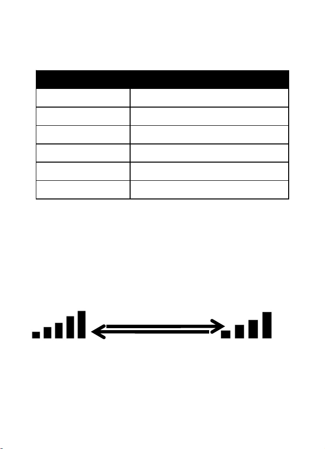
3.6 Wireless Signal Strength Indicator
During the synchronization, it will reduce one signal
segment if it has not received the signal once from the
transmitter. It will increase one signal segment if it has
received the signal once.
Received the signal once
Lost the signal once
11
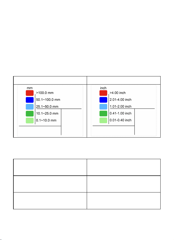
3.7 Rainfall Grade Graph
The rainfall graph displays five colors: cyan, green, blue,
dark blue, and red, each representing different rainfall
levels. The colors correspond to various rainfall
parameters across different modes.
3.7.1 Rainfall Range Represented by Colors
a) mm:
b) Inch:
Table 4
3.7.2 Rainfall Data Represented
a) Normal Mode:
Shows the historical daily
rainfall data.
b) Day Rain History
Mode:
Shows the historical daily
rainfall data.
c) Month Rain History
Mode:
Shows the historical
monthly rainfall data.
Table 5
12
4. Button operations and Operating
Different Modes
The device supports multiple operating modes to
perform specific functions. Each mode offers unique
features and button operations. The following sections
explain:
4.1 Button Operations
Figure 9 Buttons next to the display
There is a set of five buttons on the right side of the
display console. The following table briefly explains
the function of these buttons.
13
Button
Description
SET
Hold for 2 seconds to enter the setting mode.
RAIN 1/+
Press to switch the display between RATE,
EVENT, 1H, and 24H (in normal mode).
Press to increase (+) in Setting Mode.
Hold for over 5 seconds to clear the currently
displayed Rain Rate, Rain Event, or Rainfall
Total data.
RAIN 2/-
Press to switch the display between DAY,
WEEK, MONTH, YEAR, and TOTAL (in
normal mode).
Press to decrease (
–
) in Setting Mode.
Hold for over 5 seconds to clear the currently
displayed Day, Week, Month, Year, or Total
rainfall data.
RAIN 1/+ &
RAIN 2/-
Hold both RAIN 1/+ and RAIN 2/- buttons for
5 seconds to register the transmitter signal for 3
minutes.
HISTORY
Press to toggle between history records of DAY
and MONTH, or return to normal mode.
HI/LO
Press to switch the display between MAX and
MIN values (in normal mode).
Hold for 2 seconds to enter the alarm setting
and T&H&Rainfall alert setting mode.
Table 6 Console buttons

14
4.2 Normal Mode
Description:
In Normal Mode, the device displays real-time data. You
can switch between different rainfall displays using the
RAIN 1/+ and RAIN 2/- buttons.
Using the RAIN 1/+ button:
Function: Cycles through:
Rain Rate (/H)
Rain Event
Rainfall Total for 1 Hour
Rainfall Total for 24 Hours
Note: Holding the RAIN 1/+ button for over 5
seconds clears the currently displayed rainfall data.
Using the RAIN 2/- button:
Function: Cycles through:
Rainfall for the Day
Rainfall for the Week
Rainfall for the Month
Rainfall for the Year
Total Rainfall
Note: Holding the RAIN 2/- button for over 5
seconds clears the currently displayed rainfall data.

15
4.3 Setting Mode
Entering Setting Mode:
While in Normal Mode, hold the SET button for 2
seconds. The first setting parameter will begin flashing.
You can press SET again to skip any step.
Available Settings:
Beep On/Off
12/24 - Hour Format
Manual Time Setting (Hours/Minutes)
Date Format (D‑ M / M‑ D)
Date Setting (Year/Month/Day)
Temperature Unit (°C/°F)
Rainfall Unit (mm/in)
Calibration Mode
Operation Tips:
Use the RAIN 1/+ or RAIN 2/- buttons to change or
scroll through values.
Holding these buttons for 2 seconds accelerates the
change.
The device will revert to Normal Mode if idle for 15
seconds or by pressing the HISTORY button.

16
4.4 Calibration Mode
Entering Calibration Mode:
From within Setting Mode, press SET to toggle till CAL
appears.
Function:
Adjust the calibration coefficient for rainfall
measurements.
Adjustment Range: 0.1 to 5.0 (default is 1.00)
Operation:
Use the RAIN 1/+ and RAIN 2/- buttons to adjust
the coefficient.
Holding these buttons for 2 seconds changes the
value more rapidly.
Before Calibrating, Perform a Rain Gauge Accuracy
Cross Check:
Collect Water:
Use a narrow-neck bottle placed under the rain gauge’s
water outlet to collect water during a rain event.
Measure the weight (e.g., 353 g).
Calculate Rainfall Depth:
Since 353 g ≈ 353 ml, divide by the rain collector area
(250 cm²):
Calculation: 353 ml / 250 cm² = 1.412 cm, or

17
approximately 14.1 mm.
Compare Readings:
Compare this calculated rainfall depth with the reading
on your console or a calibrated manual gauge.
Adjust for Discrepancies:
Note that due to residual water in the tip bucket and on
the collector, the measured rainfall is usually slightly less
(within 5%) than the actual amount.
If the deviation exceeds 5%, adjust the calibration
settings accordingly or contact customer service for
replacement.
Simple Accuracy Check:
1. Remove the rain collector top.
2. Tap the spoon-shaped part inside the bucket 10 times
(one tap every 2 seconds).
3. Verify that the console registers approximately 1.0
mm of rainfall after 5 minutes.
4.5 Rain History Mode
Entering Rain History Mode:
While in Normal Mode:
Single Press of the HISTORY button: Enters Day Rain

18
History Mode.
Double Press of the HISTORY button: Enters Month
Rain History Mode.
Operation:
Use the RAIN 1/+ or RAIN 2/- buttons to scroll through
historical rainfall data records by day or month.
4.6 MIN/MAX Mode
Entering MIN/MAX Mode:
While in Normal Mode, press the HI/LO button.
Function:
Press the HI/LO button to cycle through maximum and
minimum records (with timestamps) for:
Indoor Temperature (Max/Min)
Indoor Humidity (Max/Min)
Note:
Holding the HI/LO button for over 5 seconds clears
the currently displayed MAX/MIN records.
The device will return to Normal Mode if idle for 15
seconds.

19
4.7 Alarm/Alert Setting Mode
Entering Alarm/Alert Setting Mode:
While in Normal Mode, hold the HI/LO button for 2
seconds. The first alarm setting will begin flashing. Press
HI/LO again to skip any step.
Available Settings:
TIME ALARM: ON/OFF
TIME ALARM Value (Hour/Minute)
Rainfall Rate HI Alert: ON/OFF
Rainfall Rate HI Alert Value
Rainfall Event HI Alert: ON/OFF
Rainfall Event HI Alert Value
Indoor Temperature HI Alert: ON/OFF
Indoor Temperature HI Alert Value
Indoor Temperature LO Alert: ON/OFF
Indoor Temperature LO Alert Value
Indoor Humidity HI Alert: ON/OFF
Indoor Humidity HI Alert Value
Indoor Humidity LO Alert: ON/OFF
Indoor Humidity LO Alert Value

20
Operation Tips:
Use the RAIN 1/+ or RAIN 2/- buttons to change or
scroll through values. Holding these buttons for 2
seconds will change values rapidly.
When an alarm threshold is reached, the
corresponding alarm icon flashes and the buzzer
rings for 2 minutes. Press any button to stop the
buzzer.
The device will revert to Normal Mode if idle for 15
seconds or by pressing the HISTORY button.

21
5. Factory Reset and Rain Gauge
Sensor Registration
5.1 Reset to Factory
Step 1: Remove the battery from the device.
Step 2: Hold the SET and the HI/LO buttons.
Step 3: While still holding these buttons, reinsert the
battery to power up the display.
The device will boot into Factory Mode, and all
previously configured settings will be reset to their
default values.
5.2 Rain Gauge Sensor Registration:
While in Normal Mode, hold the RAIN 1/+ and RAIN
2/- buttons for 5 seconds.
The device will then register the transmitter signal for
3 minutes.

22
6. Features
1. Date & Time:
Calendar display: Month/Day, year range
(2017-2099, default year 2019).
Selectable 12/24-hour format.
Built-in alarm clock with customizable settings.
2. Indoor Temperature & Humidity:
Measures indoor temperature and humidity every 60
seconds.
Records MAX and MIN temperature and humidity
with timestamps.
High and low temperature/humidity alerts.
3. Rain Measurement:
Receives data from the wireless rain sensor every 49
seconds.
Rain1 displays: Rain Rate, Rain Event, 1-Hour,
24-Hour rainfall data.
Rain2 displays: Daily, Weekly, Monthly, Yearly, and
Total rainfall data.
Rain Rate/Event data displayed in graph format.
Rain Rate alerts and Event alerts.
4. Rainfall History:
Stores up to 24 months of rain history and 730 days
of rainfall records.

23
7. Troubleshooting Guide
Problem
Solution
Wireless remote
(outdoor
sensor) not
reporting in to
console.
There are
dashes (--) on
the display
console.
Check the remote-transmitter LED
for flashing.
The outside sensor has an LED under
the plastic, just above the battery
compartment. The LED will flash
every 49 seconds.
If the LED is not flashing every 49
seconds, replace the batteries in the
outside sensor.
If the batteries were recently
replaced, check the polarity.
If the sensor is flashing every 49
seconds, proceed to the next step.
There may be a temporary loss of
communication due to reception loss
related to interference or other
location factors, or the batteries may
have been changed in the remote and
the console has not been reset.
The solution may be as simple as
powering down and up the console.
24
Problem
Solution
1. Make sure you have fresh batteries
in the display console.
2. With the sensor array and console
10 feet away from each other,
remove the batteries from the
display console and wait 10
seconds. Put the batteries back in.
3. Do not touch any button for several
minutes.
4. If the rainfall data is still showing
dashes (--) after 3 minutes, the
remote sensor is defective. If the
sensor properly syncs up, proceed
to the next step “How to prevent
intermittent wireless
communication”.
How to prevent intermittent
wireless communication issues:
1. Install a fresh set of batteries in the
remote sensor array and console.
For cold weather environments,
install lithium batteries.
2. The maximum line of sight
25
Problem
Solution
communication range is 300" but
most users will get 100" or less due
to environmental conditions. Move
the sensor and remote closer
together.
3. If the sensor assembly is too close
(less than 5’), move the sensor
assembly away from the display
console.
4. Make sure the remote sensors are
not transmitting through solid
metal like aluminum siding (acts as
an RF shield), or earth barrier
(down a hill).
5. Move the display console around
electrical noise generating devices,
such as computers, TVs and other
wireless transmitters or receivers.
6. Move the remote sensor to a higher
location. Move the remote sensor
to a closer location.
Temperature
reads too high
in the day time.
Make sure the console is placed in a
shaded area on the north facing wall.
Display console
Replace console batteries with a fresh
26
Problem
Solution
contrast is weak
set of batteries.
8. Specifications
Transmission distance(from
WH40/WH40H) in open
field
100m(328 ft)
Frequency
915/868/433MHz
depending on location
(North American:915MHz;
Europe:868MHz; Other
areas:433MHz)
Indoor temperature and
humidity data measuring
interval
60s
Indoor temperature
measuring range
-9.9˚C–60˚C (14℉–
140℉)
Indoor temperature accuracy
± 1°F / ±0.56°C
Indoor humidity measuring
range
10%–99%
Indoor relative humidity
accuracy (at 25°C):
±6% for 30–80% RH
±5% for 1–29% & 80–
99% RH

27
Power supply
3xAA Alkaline batteries
(not included)
Battery life
12 months
Table 7
9. Warranty Information
We disclaim responsibility for any technical error or
printing error or the consequences thereof.
All trademarks and patents are recognized.
We provide a 2 years limited warranty on this product
against manufacturing defects or defects in materials and
workmanship.
This limited warranty begins on the original date of
purchase, is valid only on products purchased, and only
to the original purchaser of this product. To receive
warranty service, the purchaser must contact us for
problem determination and service procedures.
This limited warranty covers only actual defects within
the product itself and does not cover the cost of
installation or removal from a fixed installation, normal
set-up or adjustments, or claims based on

28
misrepresentation by the seller, or performance
variations resulting from installation-related
circumstances.
Manufacture: Shenzhen Fine Offset Electronics Co., Ltd.
Address: 4/F, Block C, JiuJiu Industrial City, Shajing
Town, Baoan District, Shenzhen City, China
10. FCC
This device complies with part 15 of the FCC Rules.
Operation is subject to the condition that this device does
not cause harmful interference (1) this device may not
cause harmful interference, and (2) this device must
accept any interference received, including interference
that may cause undesired operation.
Changes or modifications not expressly approved by the
party responsible for compliance
could void the user's authority to operate the equipment.
NOTE: This equipment has been tested and found to
comply with the limits for a Class B digital device,
pursuant to Part 15 of the FCC Rules. These limits are
designed to provide reasonable protection against
harmful interference in a residential installation. This
equipment generates, uses and can radiate radio
frequency energy and, if not installed and used in
accordance with the instructions, may cause harmful

29
interference to radio communications. However, there is
no guarantee that interference will not occur in a
particular installation.
If this equipment does cause harmful interference to
radio or television reception,
which can be determined by turning the equipment off
and on, the user is encouraged to try to correct the
interference by one or more of the following measures:
-- Reorient or relocate the receiving antenna.
-- Increase the separation between the equipment and
receiver.
-- Connect the equipment into an outlet on a circuit
different
from that to which the receiver is connected.
-- Consult the dealer or an experienced radio/TV
technician for help.
To maintain compliance with RF Exposure guidelines,
This equipment should be installed and operated with
minimum distance between 20cm the radiator your body:
Use only the supplied antenna.
IC Caution:
English:
This device contains licence-exempt

30
transmitter(s)/receiver(s) that comply with Innovation,
Science and Economic Development Canada’s
licence-exempt RSS(s). Operation is subject to the
following two conditions:
1. This device may not cause interference.
2. This device must accept any interference, including
interference that may cause undesired operation of the
device.
French:
L’émetteur/récepteur exempt de licence contenu dans le
présent appareil est conforme aux CNR d’Innovation,
Sciences et Développement économique Canada
applicables aux appareils radio exempts de licence. L’
exploitation est autorisée aux deux conditions suivantes :
1. L’appareil ne doit pas produire de brouillage;
2. L’appareil doit accepter tout brouillage radioélectrique
subi, même si le brouillage est susceptible d’en
compromettre le fonctionnement.

31
11. Contact Us
11.1 After-sales Service
Order Issues:
If you encounter any missing or incorrect shipments of
Ecowitt products purchased, please reach out to the
respective platform's customer service from the store
where you bought the product for assistance.
Usage Inquiries:
Our product is continuously changing and improving,
particularly online services and associated applications.
To download the latest manual, and additional help, and
for any issues related to product usage feel free to
contact our customer support team at
support@ecowitt.com.We are committed to providing
assistance and resolving any concerns you may have.

32
11.2 Stay in Touch
Ask questions, watch setup videos, and provide feedback
on our social media outlets. Follow Ecowitt on
Discord,Facebook,YouTube and Twitter.
Copyright © 2025 ecowitt All Rights Reserved. DC030425