
User Manual
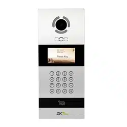
VEX-B21A
Version: 1.0
Due to the regular upgrades of systems and products, ZKTeco could not guarantee exact
consistency between the actual product and the written information in this manual.
Remark
Please follow the user manual for correct installation and testing. If there is any
doubt please call our tech-supporting and customer center.
Our company applies ourselves to reformation and innovation of our products.
No extra notice for any change. The illustration shown here is only for
reference
. If there is any difference, please take the actual product as the
standard.
The product and batteries must be handled separately from household waste.
When the product reaches the end of service life and needs to be discarded,
please contact the local administrative department and put it in the
designated collection points in order to avoid the damage to the environment
and human health caused by any disposal. We encourage recycling and
reusing the material resources.

CATALOG
Pictures .............................................................................. 1
Basic Function .................................................................2
Technical Parameters. .................................................... 2
Product Standard........................................................... 3
Package Contents ........................................................... 3
Basic Operation .............................................................. 4
Basic Settings ................................................................. 7
Web Settings ................................................................... 14
System Configuration .....................................................19
System Diagram..............................................................20
Installation ......................................................................23
Troubleshooting. ............................................................25
Safety Precaution. ...........................................................26
1
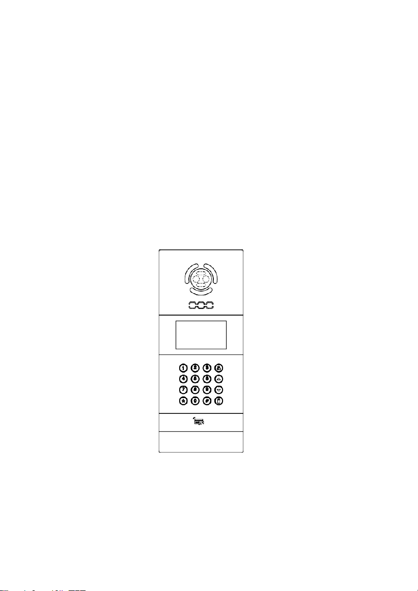
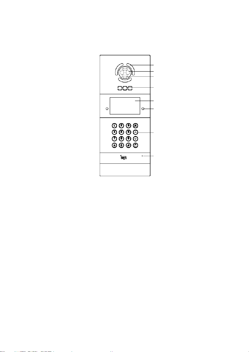
Pictures
Model: VEX-B21A
LED Light
Camera
Liveness detection
Speaker
Display screen
Infrared detection
Digital keypad
Microphone

2
Basic Function
1. Video intercom with indoor monitor and management center;
2. Support unlocking by access password, IC/ID card(ID card is optional) or facial
recognition;
3. It can register IC/ID card information on the outdoor panel and store up to 100,000 IC/ID
cards(ID card is optional);
4. Support Exit button unlocking and door magnetic detection;
5. Infrared detection function;
Technical Parameters
1. Working voltage: DC12V
2. Rated power: 10W
12W (Heating membrane)
3. Standby power: 3W
5W (Heating membrane)
4. Display screen: 4.3'' (480RGB*272)
5. Working temperature: -10℃~+70℃
-40℃~+70℃ (Heating membrane)
6. Storage temperature: -10℃~+70℃
7. Humidity: 20%~93%
8. CPU: Quad-core 1.3GHz
9. SDRAM: 512MB
10.
Flash: 8GB
11.
Camera: 1280*720CMOS
1920*1080CMOS
3
Product Standard
◇ GB/T 31070.1-2014 "Building Intercom Systems—Part 1: General Technical
Requirements".
◇ GA 1210-2014 "Security Technical Requirements for Building Intercom Systems".
◇ GB /T12663-2019 "General Specifications for Burglar-alarm Control Units".
◇ GB /T 32581-2016 "Specifications for Intrusion and Hold-up Alarm System".
◇ GBT / 31070.2-2018 "Building Intercom System Part 2: Technical Requirements for
Digital Building Intercom Systems".
◇ GBT / 31070.4-2018 "Building Intercom System Part 4: Application Guidelines".
◇ GB / T 37845-2019 "Technical Requirements for Home Security Intelligent
Management Systems".
◇ DB31 / T294-2018 "Requirements of Intelligent Security Technology in Residential
District".
◇ DB31T 1086-2018 "Requirements of Applications for Intrusion Alarm System".
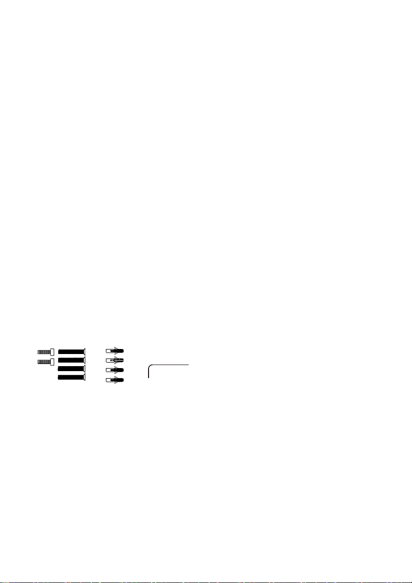
Package Contents
Model: VEX-B21A
Screw Expansion
Tube
Screw Wrench
4
Press * twice to start face recognition.
Press * twice to start face recognition.
0000
Press * twice to start face recognition.
Building: 0000
Press * twice to start face recognition.
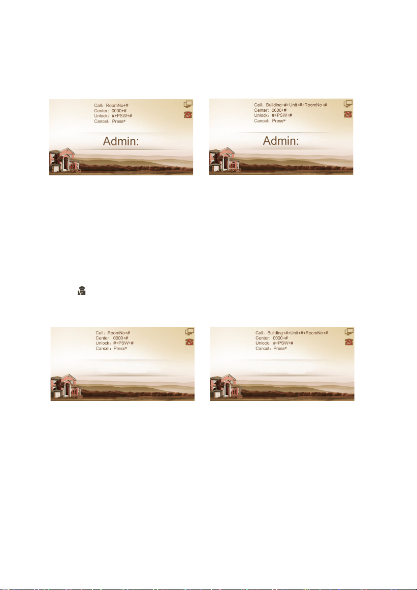
Basic Operation
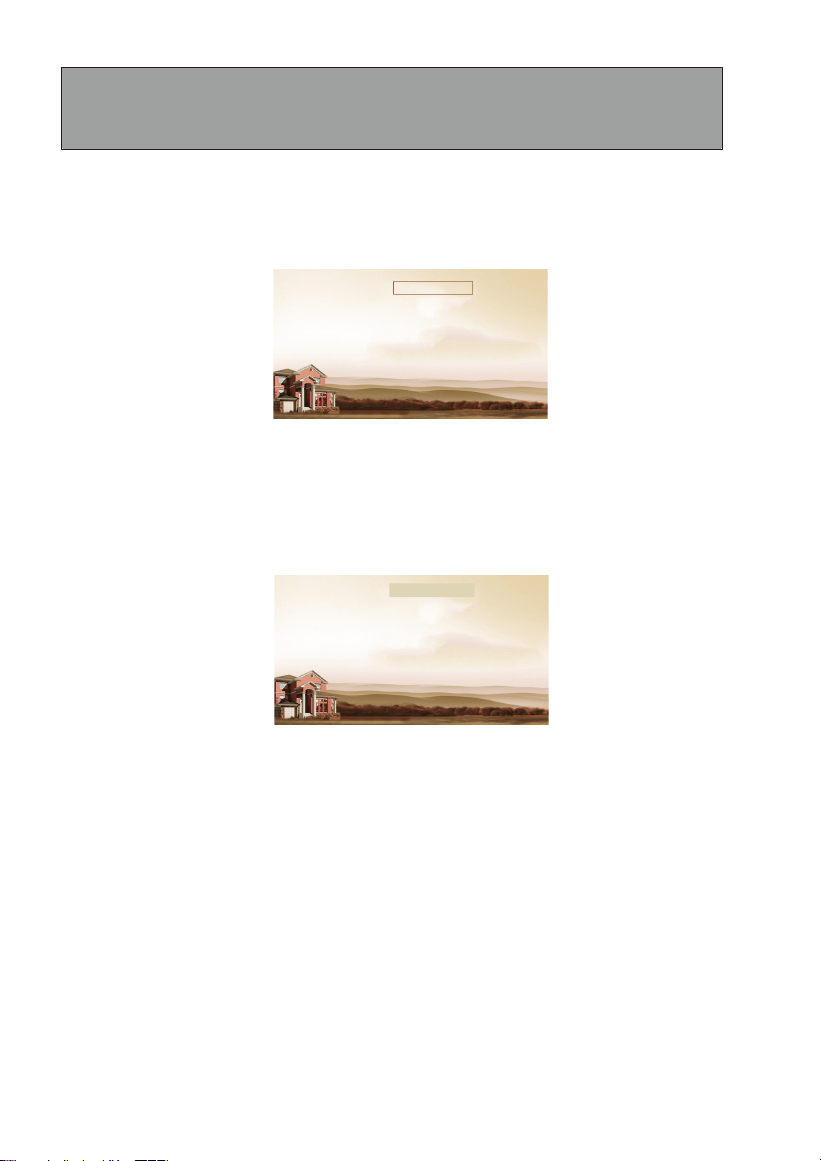
After the outdoor panel is powered on, if it is set as the unit panel, the LCD display is as shown
in figure (1); if it is set as the wall panel, the LCD display is as shown in figure (2):
Figure (1)
Figure (2)
1. Call management center by unit panel or wall panel
In a standby mode, inputting "0000"(4 digits) on unit panel, the LCD display is as shown in
figure (3); inputting "0000"(4 digits) on wall panel, the LCD display is as shown in figure (4).
Then press "#" to enter the call state.
Note: Press " " to call management center directly. During ringing, press "*" key to
cancel the
call.
Figure (3) Figure (4)
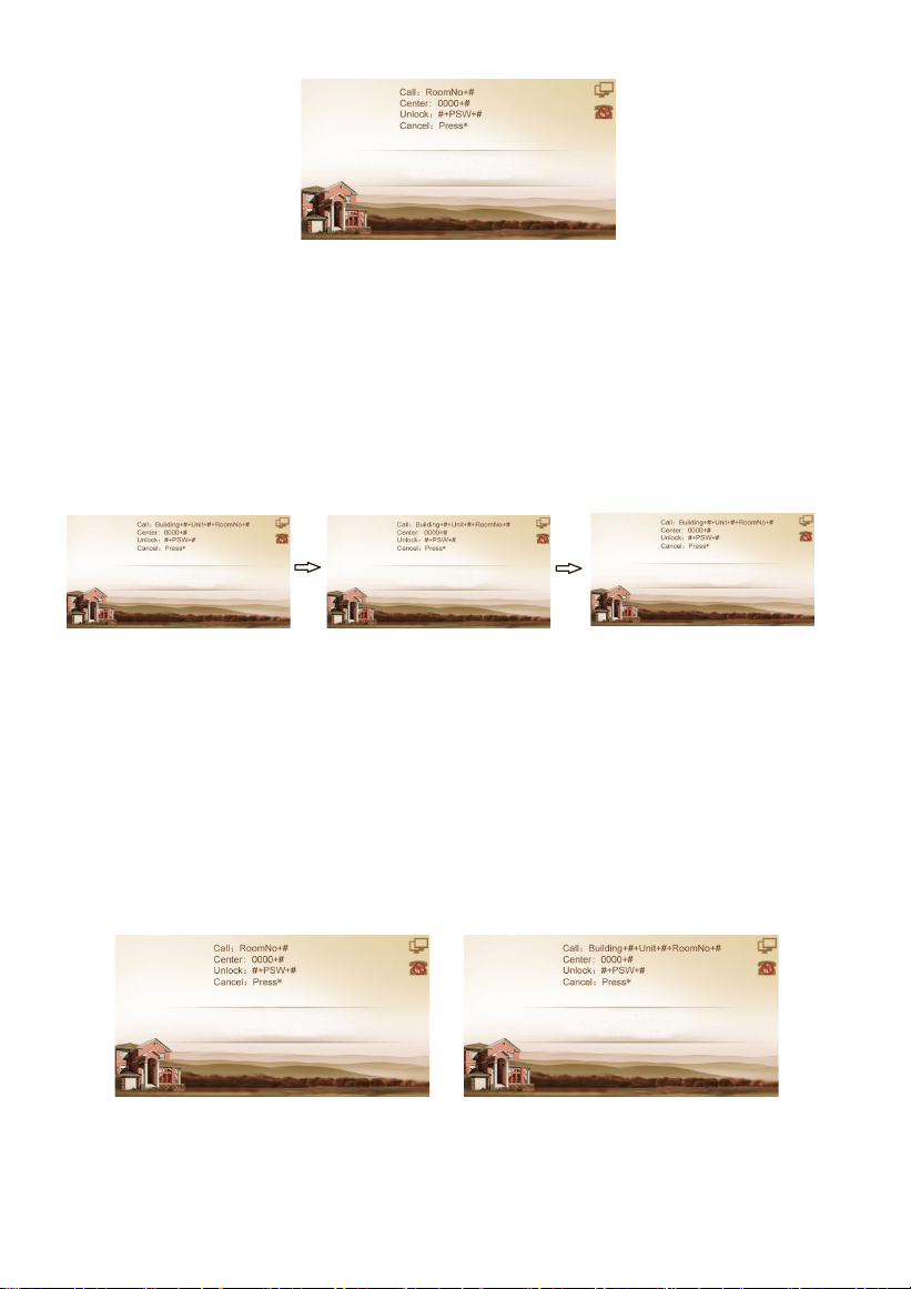
2. Call indoor monitor
2.1 Call indoor monitor by unit panel
In a standby mode, enter 2-dight floor No. + 2-digit room No. of the indoor monitor. For
example, the floor No. is 13, and the room No. is 12. Enter "1312" directly, the LCD display is as
shown in figure (5). Then press "#" key to start calling.
5
Building: 1
Press * twi ce to st art fac e rec ogni tio n.
Unit: 1
Room: 1312
Press * twi ce to st art fac e rec ogni tio n.
Password:
Press * twice to start face recognition.
Password:
Press * twice to start face recognition.
Figure (5)
2.2 Call indoor monitor by wall panel
In a standby mode, enter 3-dight building No. + # +2-dight unit No. + # + 2-digit floor No. + # +
2-digit room No. of the indoor monitor. For example, the building No. is 0001, the unit No. is
01, the floor No. is 13, and the room No. is 12. Entering "1"+ "#" + "1" + "#" + "1312" directly, the
LCD display is as shown in figure (6), figure (7), figure (8). Then press "#" key to start calling.
Figure (6)
Figure (7)
Figure (8)
3. Unlock the door
3.1. Unlocking by access password
In the interface shown in figure (1) or figure (2), pressing "#" key and entering the access
password(default is 0000), the unit panel is as shown in Figure (9), and the wall panel is as
shown in Figure (10), then press "#" key to confirm. If the password is correct, the door will be
unlocked; if not, it will make a sound like "Deng Deng".
Note: Please refer to 3.3 Password in Basic Settings for password modification.
Figure (9)
Figure (10)
1312
Press * twice to start face recognition.

6
3.2. Unlocking by IC/ID card (ID card is optional)
Put the registered IC/ID card on card reader area of the outdoor panel. If successful, the door
will be unlocked.
3.3. Unlocking by Face Recognition
When someone puts face close to the LCD screen, outdoor panel will automatically start the
face recognition or the user can press the "*" key twice to enable the face recognition. If the
face has been registered, the door will be unlocked.
7
Press * twice to start face recognition.
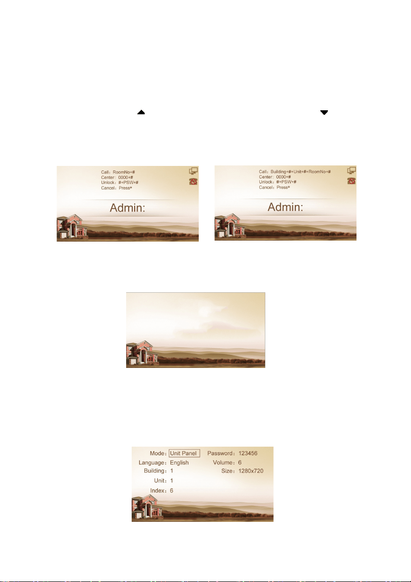
Basic Settings
In the interface shown in figure (1) or figure (2), pressing the "#" key twice, LCD display of unit
panel is as shown in figure (11), LCD display of wall panel is as shown in figure (12). Enter six-
digit admin password (default password: 123456) and go to settings.
Press the number key "2" or icon to page up, press the number key "8" or icon to page
down; press "#" key to confirm; press "*" key to return. After selecting the item to be set, press
the "#" key to enter the settings or press the "*" key to cancel the settings.
Figure (11)
Figure (12)
Outdoor panel enters the setting interface, and the LCD display is as shown in figure (13):
1.
Device Settings
Figure (13)
Select "Device Settings" and press the "#" key to enter the device settings submenu, the LCD
display is as shown in figure (14):
Figure (14)
Press * twice to start face recognition.
1. Device Settings
2. Network Settings
3. Access Settings
4. Face Settings
5. Misc Settings
6. About System
8
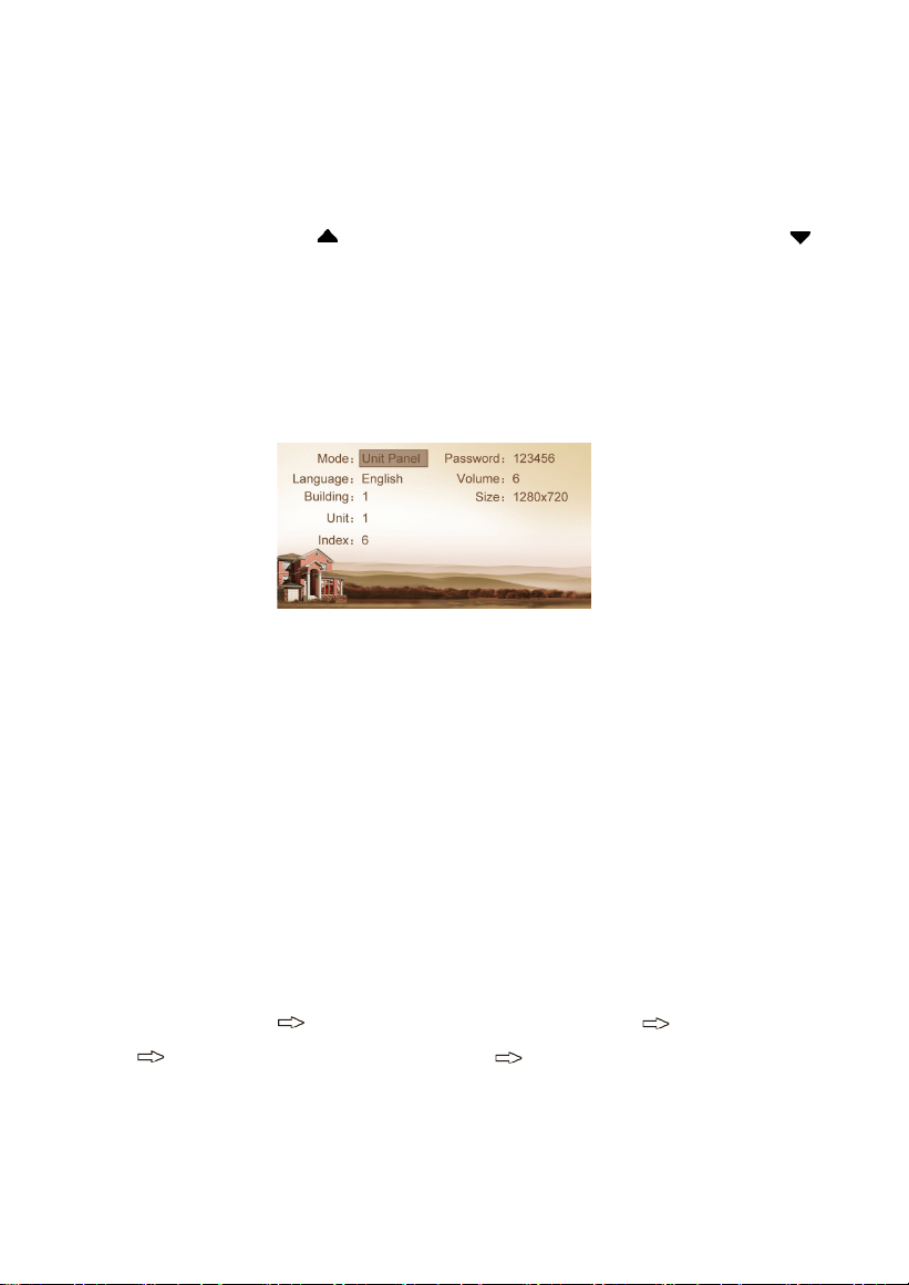
1.1 Device Mode
The device can be used as unit panel or wall panel. The device mode can be set through this
item.
Press the key "#" to go to settings. The LCD screen will display as shown in Figure (15). Press
the number key 2 or the icon to page up, and press the number key 8 or the icon to
page down. If the device is used as unit panel, it can only call the indoor monitors in this unit.
If the device is used as wall panel, it can call all the indoor monitors in the whole community.
Once it’s selected, press the pound key "#" to confirm. When the outdoor panel gives an
indication tone, it means that it is changed successfully. Press "*" to cancel the settings.
Figure (15)
1.2 Language, Volume and Size
The language, volume and size (resolution) are set in the same way as the settings of device
mode.
"Language" is used to set the language to be shown on the outdoor panel, supporting
simplified Chinese, English and traditional Chinese.
"Volume" is used to set the prompt tone of outdoor panel, including 1-6 volume levels
selection.
There is 320x240, 640x480 or 1280x720 for the size.
1.3 Building No., Unit No., Index and Password
Select the item for setting Press the pound key "#" to go to settings Input the number to
change Press the pound key "#" to confirm When the outdoor panel gives an
indication tone, it means that it is changed successfully(Press the star key "*" to cancel the
settings).
9
DHCP: Enable
IP: 192.168.68.103
Mask: 255.255.255.0
Gateway: 192.168.68.1
DNS: 8.8.8.8
Server: 192.168.1.100
DHCP: Enable
IP: 192.168.68.90
Mask: 255.255.255.0
Gateway: 192.168.68.1
DNS: 8.8.8.8
Server: 192.168.68.1
2.
Network Settings
Select "Network Settings" and press the pound key "#" to access the submenu.
The LCD screen will show as follows:
Figure (16)
2.1 DHCP
Select this item and press the pound key "#" for setting. The LCD screen will show as follows.
The user can enable or disable the function.
Figure (17)
2.2 IP
The default IP address of the system is 192.168.68.90. The LCD screen will display as shown
above. As for the devices which are connected on the same LAN (the same subnet of network
segment), their IP addresses cannot be the same.
2.3 Mask
The system default is 255.255.255.0. The LCD screen will display as shown above.
2.4 Default Gateway
It refers to the gateway address for network segment of device’s IP address. The system default
is 192.168.68.1. The LCD screen will display as shown above.
Note: Please keep the admin password confidential. If the password is forgotten,
the user will not be able to log into the system. The password can only be
recovered by resetting to factory defaults.
10
2.5 DNS
The system default is 8.8.8.8. The LCD screen will display as shown above.
2.6 Server
The server address refers to the IP address of computer with management software. In case
that management software isn’t required for managing the intercom devices, this setting is
invalid. The default IP address of server is 192.168.68.1. The LCD screen will display as shown
above.
3.
Access Settings
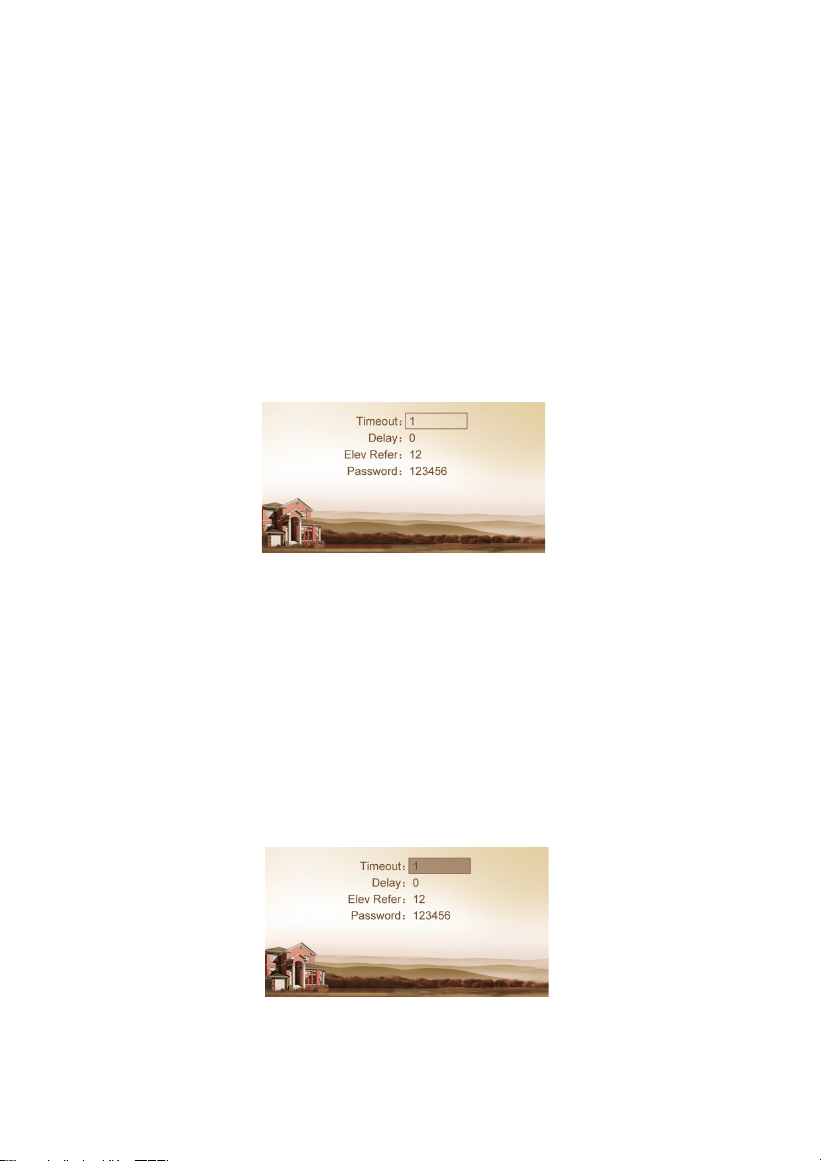
Select "Access Settings" and press the pound key "#" to access the submenu. The LCD screen
will show as follows:
Figure (18)
3.1 Timeout
The item is used for controlling the unlocking time, namely, how long it will take the door to
shut automatically after unlocking.
Select the item and press the pound key "#" to go to settings. The LCD screen will show as
follows. Input any number from 1 to 9. If the user enters the number 8, it means the
unlocking time is set at 8 seconds. Press the pound key "#" to confirm after inputting.
When the outdoor panel gives an indication tone, it means that the time is changed
successfully.
Figure (19)

11
Recognizer: Disable
Similarity: Low
Live Detect: Enable
Register: Room No.
Face Clear: Press 1#
Recognizer: Disable
Similarity: Low
Live Detect: Enable
Register: Room No.
Face Clear: Press 1#
3.2 Delay
The item is used for setting the delayed opening time, meaning how long it will delay
unlocking the door after the user presses the unlock button on the indoor monitor.
Select the item and press the pound key "#" to go to settings. The LCD screen will display as
shown above. Input any number from 1 to 9. If the user enters the number 5, it means the
delayed opening time is set at 5 seconds.
Press the pound key "#" to confirm after inputting. When the outdoor panel gives an
indication tone, it means that the time is changed successfully.
3.3 Password
The item is used for setting the password to unlock the door. Enter the passwords and then press
the pound key "#" to confirm. The LCD screen will display as shown above.
3.4 Elev Refer (This item can only be used after connection to elevator control
devices)
The item is used for setting the floor of outdoor panel.
Select the item and press the pound key "#" to go to settings. The LCD screen will display as
shown above. Set the floor No. of outdoor panel ranging from 01 to 99. After the door is
unlocked, the elevator will reach the floor of outdoor panel.
Press the pound key "#" to confirm after inputting. When the outdoor panel gives an
indication tone, it means that it is changed successfully.
4.
Face Settings
Select "Face Settings" and press the pound key "#" to access the submenu. The LCD screen will
show as follows:
Figure (20)
Figure (21)
12
The item "Recognizer" is used for setting the state of recognizer function. "Disable" means the
function has been closed. Select the item and press the pound key "#" to go to settings. The
LCD screen will display as shown above.
The item "Similarity" is used for setting the face similarity. There are 3 levels to choose. Select
the item and press the pound key "#" to go to settings.
The item "Live Detect" means that you can move when being recognized. Select the item and
press the pound key "#" to go to settings.
The item "Register" is used for recording the new face. Enter the room number and then
register the face on the system of outdoor panel. When the system gives a prompt tone, it
means the registration is completed.
The item "Face Clear" is used for clearing the registered information. Enter 1 and then press
the pound key "#" to confirm.
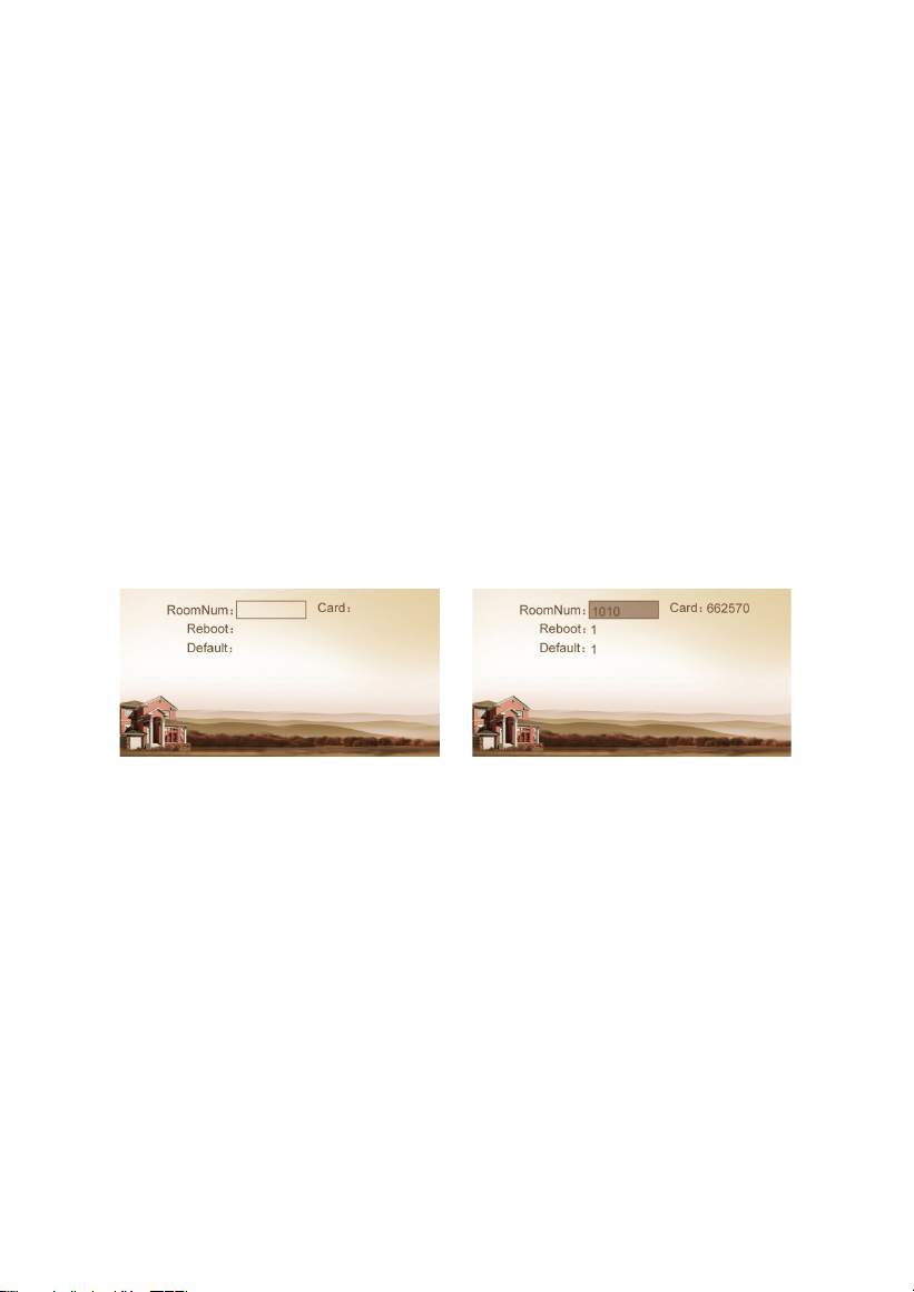
5.
Misc Settings
Select "Misc Settings" and press the pound key "#" to access the submenu. The LCD screen will
show as follows:
Figure (22)
Figure (23)
The item "RoomNum" is used for registering the access card corresponding to the room
number. Select the item and press the pound key "#" to go to Settings. The LCD screen will
display as shown above.
Enter the room number and then place the access card close to the swiping area. When the
outdoor panel gives an indication tone, it means that the card has been registered
successfully. Then the No. of registered card will be displayed.
The item "Reboot" is used for restarting the outdoor panel. Enter the number "1" and then
press the pound key "#" to confirm. The system will restart automatically. Entering any
number other than "1" is invalid.
The item "Default" is used for resetting to system default. Enter the number "1" and then press
the pound key "#" to confirm. The system will be reset. Entering any number other than "1" is
invalid.

13
FW: 1.6.0 20180919
UI: 1.8.2 20180918(std)
MCU: 1.3.0
IP: 192.168.68.90
MAC: BC:FB:11:01:5C:6E
SIP:ERROR
6.
About System
Select "About System" and press the pound key "#" to access the submenu. The LCD screen
will show as follows:
Figure (24)
14
Web Settings
Connect outdoor panel and PC to the network switch and make them on the same LAN. Input
IP address of outdoor panel in the web browser of PC, then input the user name and
password (the default name is admin, the password is 123456) to enter into the following
interface:
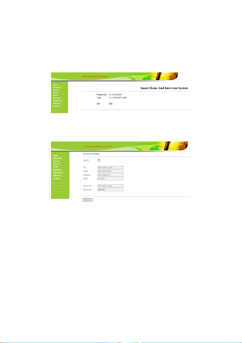
1.
Network Settings:
Click "Network" icon on the interface to enter into the following interface:
IP: IP address should be unique in the same Network.
Mask: the default Mask is 255.255.255.0.
Gateway: it depends on IP address.
DNS: it depends on Network.
Server IP: it is the same as the IP address of management PC.
NTP: it refers to network time protocol.
Usually, the communication among management center, indoor monitor and outdoor panel
will be available on the same LAN; if they are not on the same Network, you need to set SIP
server to support the communication.
Click "Submit" icon to confirm settings.
15
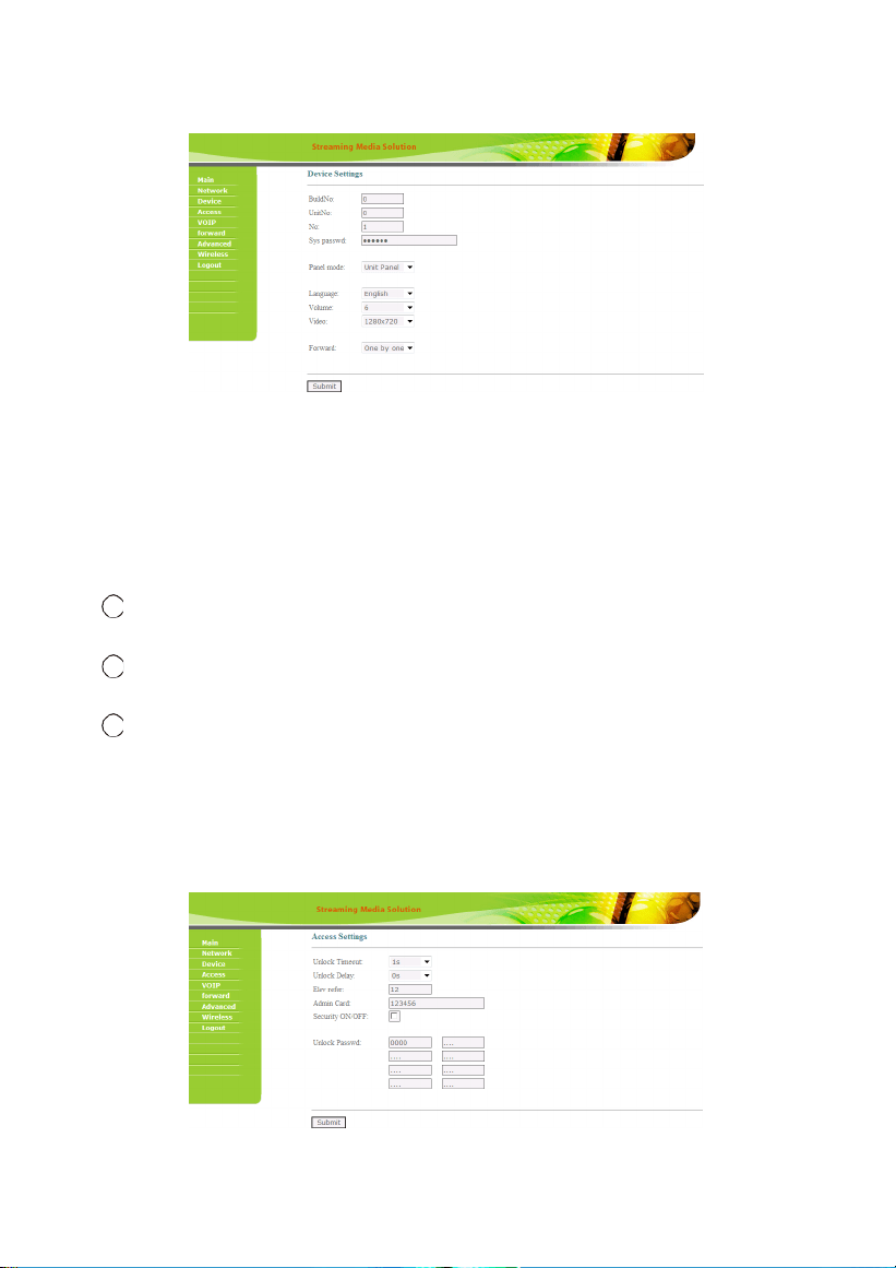
2.
Device Settings:
Click "Device" icon on the interface to enter into the following interface:
The settings of building and Unit No. should be the same as that of corresponding outdoor panel.
No.: It is unique number for the outdoor panel. You can have max.9 outdoor panels in one
house, and you need to distinguish their numbers from 1 to 9.
Sys password: you can change the login password as you like (the default password is
123456).
Panel mode: unit panel, wall panel or personal panel for selection.
1
center;
Unit panel: Used in one unit, it can call residents in the unit and management
2 Wall panel: Used at the entrance of community, it can call all indoor monitors in the
community and management center;
3
Personal panel: It is reserved.
You can choose different ringtone and language, and can also adjust the ringing volume.
Click "Submit" icon to confirm settings.
3.
Access Settings:
Click "Access" icon on the interface to enter into the following interface:

16
Unlock Timeout is used for controlling the unlocking time ranging from 1 to 9 seconds.
Unlock Delay refers to the delayed opening time ranging from 0 to 9 seconds.
Elev refer is used for setting the floor of outdoor panel ranging from 01 to 99.
Security ON/OFF: arming/disarming by card is only effective for secondary outdoor panel; unit
panel only supports disarming by card.
Unlock Passwd: it’s used for unlocking the door. The system default is 0000. Eight unlocking
passwords can be added.(This is only applicable for outdoor panel with keypad.)
Card Registration:
The Admin Card is used for registering user card. There are two ways of registering the admin
card:
1. The user enters card No. of the admin card in the box after “Admin Card” and then
click the key “Submit”. In this case, the admin card is registered successfully.
2. If the user isn’t aware of admin card No., please enter 0 in the box first and click the
key "Submit". Then place the admin card close to the swiping area. When the system gives an
indication tone, it means that the card is registered successfully.
When registering the user card, the user shall swipe the admin card first. The system emits a
beep. Then place the card to be registered near the swiping area within 10 seconds. If the
system gives an indication tone, it means that the user card is registered successfully. When
registering the user card, the card to be registered shall be swiped 10 seconds after the admin
card is swiped. Once a user card is registered, it will postpone for 10 seconds. When there is
no activity for 10 seconds, the system will exit from registration status automatically. To
register a new user card, the user shall swipe the admin card again.
4.
VOIP:
Click "VOIP" icon on the interface to enter into the following interface:
17
SIP enable: when SIP account No. is enabled, the SIP server of a third party is generally used.
Proxy: URL of SIP proxy server in format: sip:ip or sip: domain name.
Realm: realm of the device, generally the same as IP or domain name.
STUN IP and Port refer to the IP and port of public server for NAT traversal of audio and video.
Bitrate: 128K, 384K, 512K, 768K, 1M or 2M
User: user name assigned by SIP server
Password: password assigned by SIP server
Timeout: 120 seconds, 300 seconds, 600 seconds, 1200 seconds or 1800 seconds.
Ringing: ringing time of indoor monitor which is called by outdoor panel can be set. The time can be set
at 35 seconds, 45 seconds, 60 seconds, 90 seconds or 120 seconds.
Once this is set up, click the key "Submit" to enable new settings.
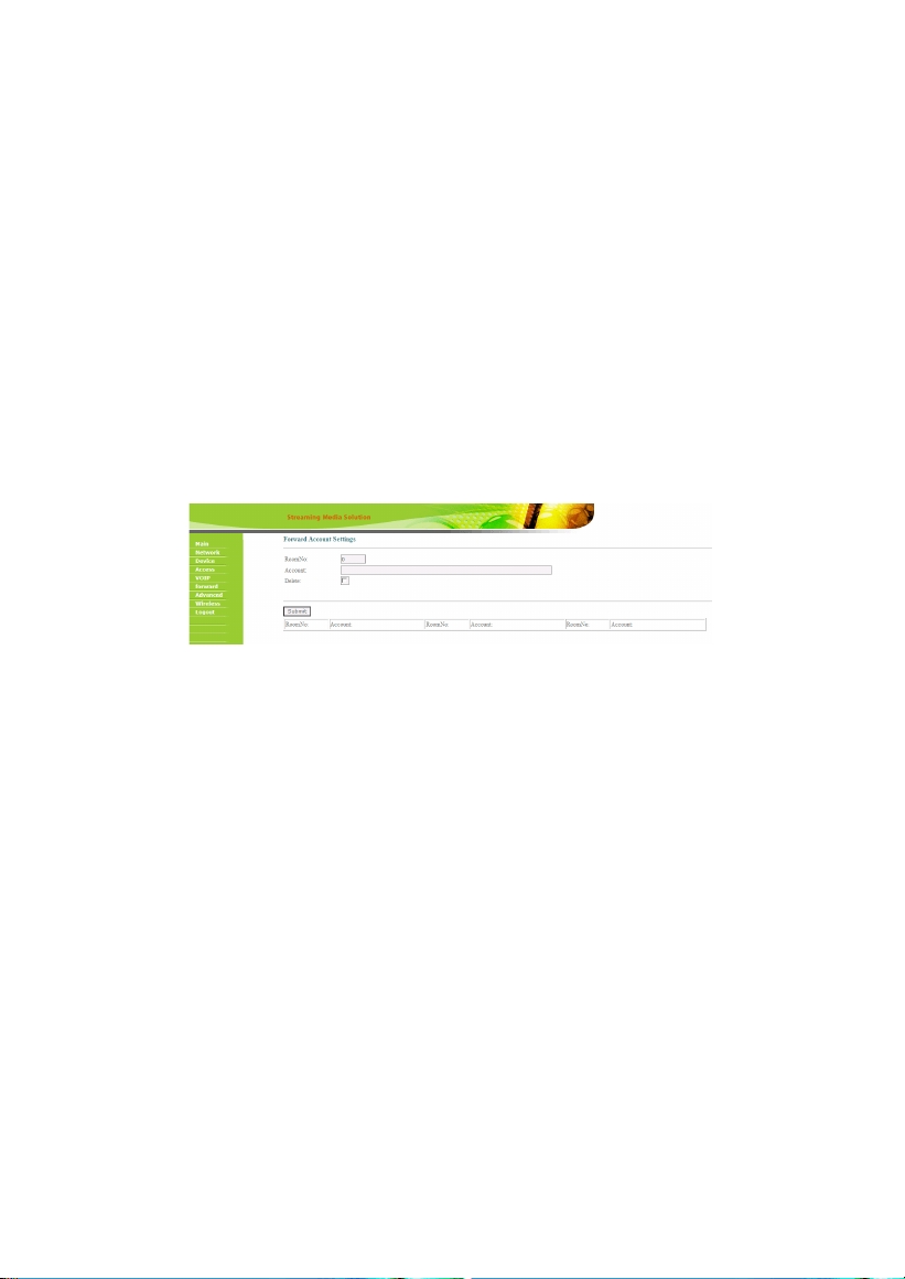
5.
Forward (Call transfer):
Click "Forward" icon on the interface to enter into the following interface:
Room No. can be bound with phone number. When the visitor calls on the outdoor panel but
there is no answer within 25 seconds, the system will forward the call to the phone. Please
follow the detailed steps:
1. Enter the room No. and then enter the account phone number to be bound;
2. To delete this account, check the box;
3. Once this is set up, click the key “Submit” to enable new settings.
(Note: This item requires support of extension module or local SIP service provider).
18
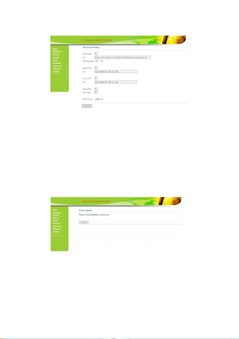
6.
Advanced
Click "Advanced" icon on the interface to enter into the following interface:
Advertising: check the box to enable this function. Enter the specified advertisement URL in
the box. The interface will play the online advertisement automatically.
Quick Call: check the box to enable this function. It refers to the call to management center.
Enter the SIP address of specified management center. The call can be from indoor monitor or
SIP internet phone of other manufacturers.
Speed Dial: press one number key to give a direct call.
Once this is set up, click the key “Submit” to enable new settings.
7.
Logout
Click "Logout" icon on the interface to enter into the following interface:
Click "Submit" icon to log out the system.
19
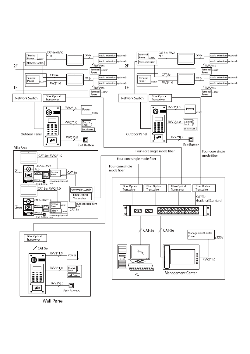
System Configuration
20
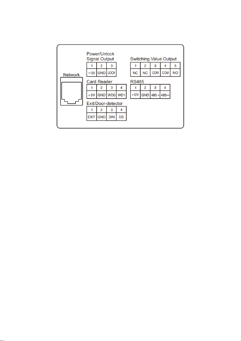
System Diagram
(Standard)
21
+12V
GND
+12V
GND
LOCK
CAT-5e
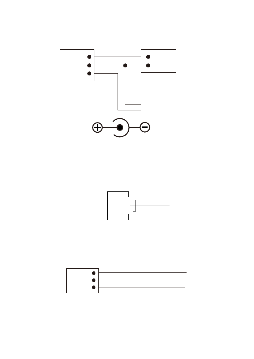
1.
Power/ Unlock Signal Output
Power interface of outdoor panel connects with 12V DC power. Unlock signal input
connects with unlock module.
Power/Unlock Signal Output
12V DC Power
Unlock Control Signal
E7 Power Interface
2.
Network
Standard RJ45 interface connects with management center, indoor monitor or other
network equipment by network switch.
Network
3.
Switching Value Output
Connect to the lock module (independent power supply is necessary for the lock).
The normally closed port of the relay
A common port of the relay
The normally open port of the relay
Switching Value Output
NC
COM
NO
22
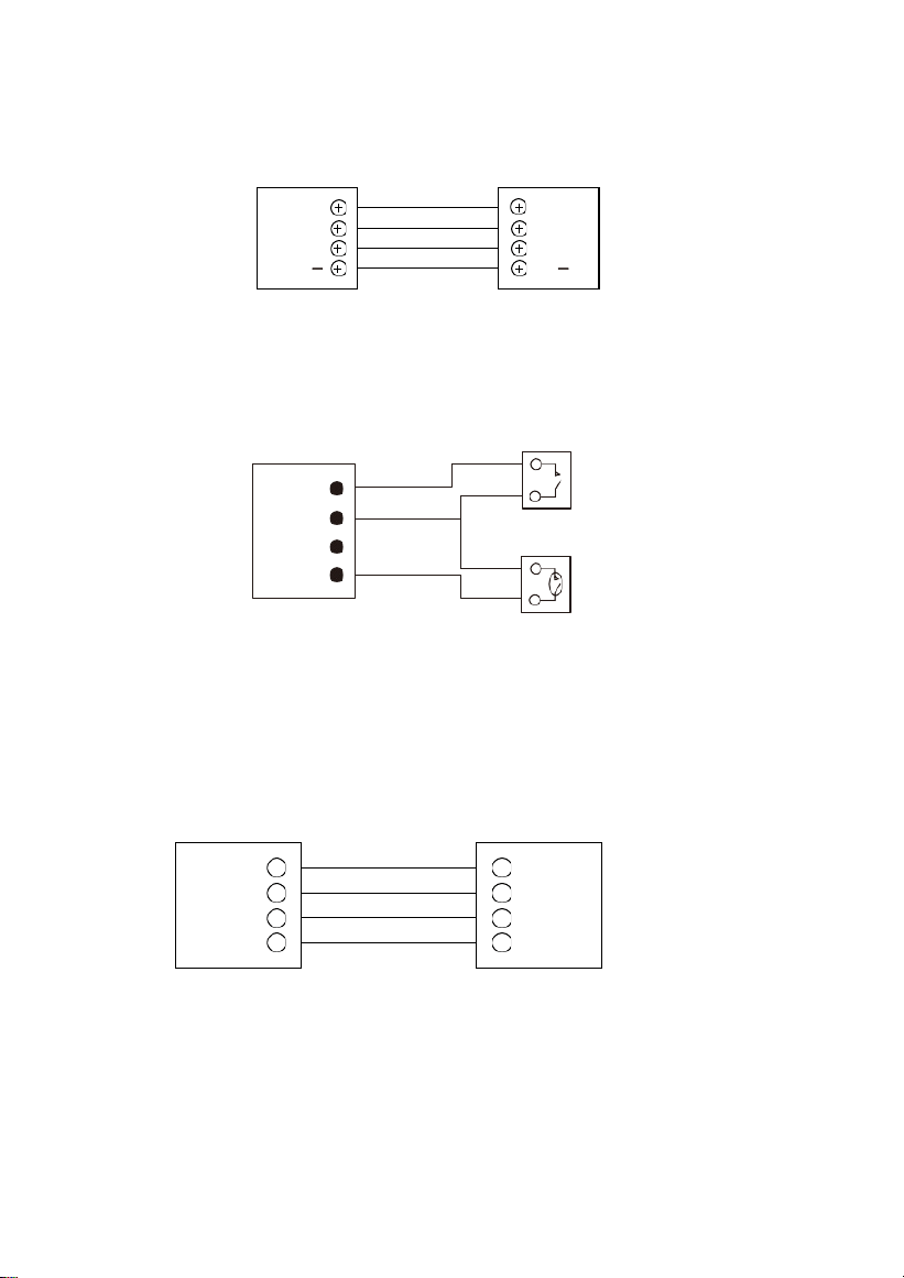
4.
RS485
Enable to connect equipment with RS485 interface. RS485 interface can output 12V/100mA
power. +12V isn’t required for wiring if it is unused.
+12V
+12V
GND
GND
485+
485+
485 485
RS485 Interface
RS485 Equipment
5.
Exit/ Door-detector
Connect with exit /door-detector; DIN is reserved terminal, please don't connect it.
Exit/Door detector
6.
Card Reader Interface
Door-detector Sense Switch
The interface can be connected to one IC/ID card reader or be used for reading the
information of built-in card reader. It can output the power 5V/100mA. When the
card reader doesn't need the power from the interface, connection of +5V isn't
required.
+5V
GND
WD0
WD1
+5V
GND
WD0
WD1
Card Reader Interface
IC/ID Card Reader or Management Device
Note: Only one card reader can be connected to outdoor panel. When there is built-in
card reader, the interface can only be used for reading the information of built-in card
reader.
EXIT
GND
DIN
DS
Exit
23
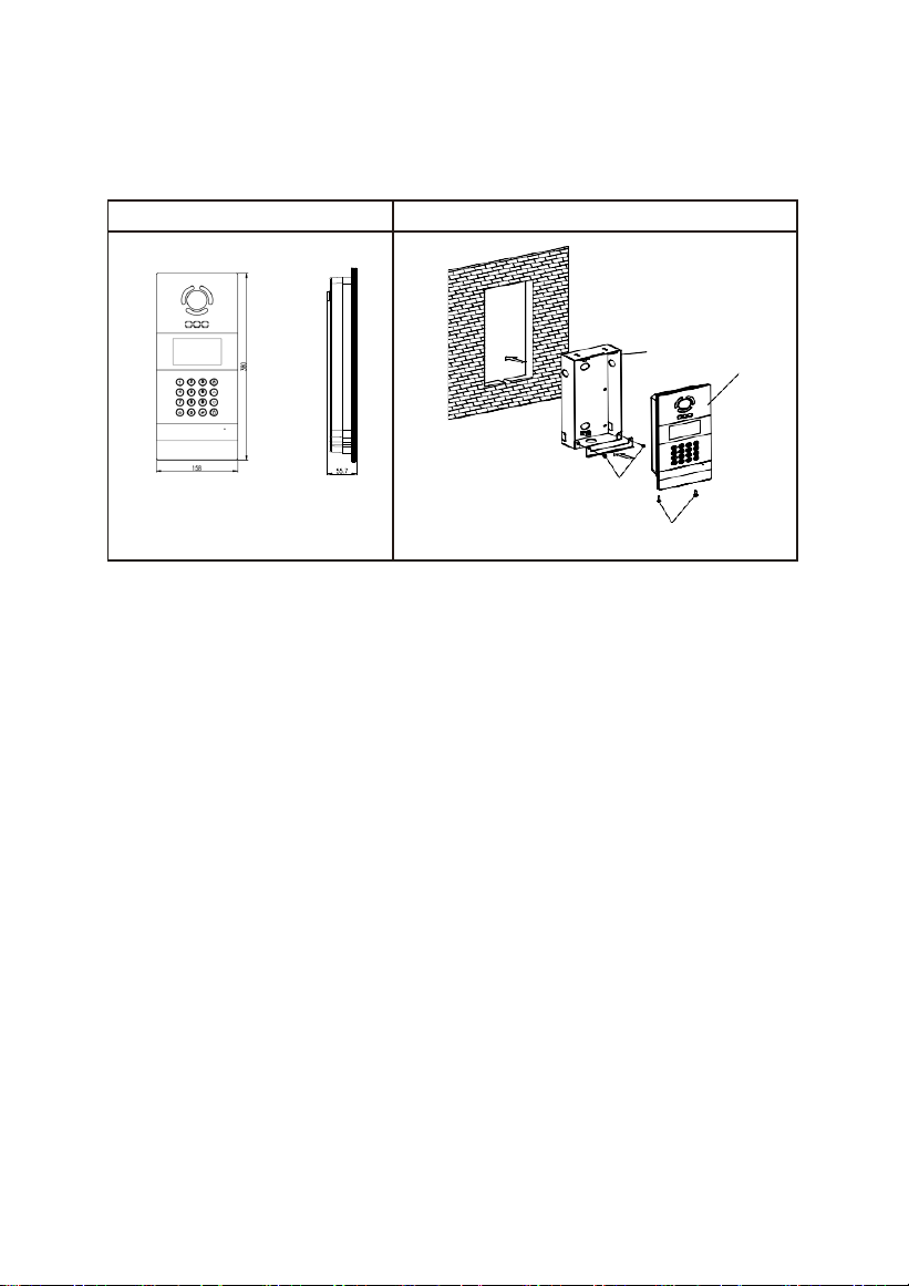
Installation
Model: VEX-B21A
Appearance dimension
Installation diagram
Dimensions: 158*380*55.7mm
Built-in box size: 142*358*59.5mm
Installation dimension: 148*364*65mm
① Outdoor panel
② Screw
③ Built-in box
②
③
②
①
24
Installation method:
1. According to the installation dimension of outdoor panel, dig a square groove at the
appropriate position in the wall or door, and dig a hole (drainage hole) at the bottom;
2. Get the hole through at the bottom of the built-in box to facilitate drainage. Upward arrow
is on the front of the built-in box. Embed the built-in box into the wall, then put the built-in
box into the groove of the wall, and tighten four screws from top to bottom of the built-in
box, or fix the built-in box in the wall with concrete;
3. Assemble the outdoor panel into the built-in box, align the groove and the built-in box,
tighten the screws, and finally inject the glass glue into the top, left and right sides of the
outdoor panel (note: the glass glue cannot be injected into the bottom part that is reserved
for the drainage hole at the bottom of outdoor panel).
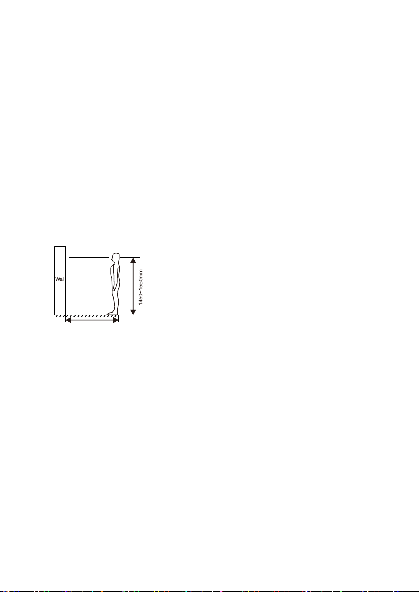
Installation Instructions:
400~500mm
[Suggestion]: During the installation, the
camera should be 1450〜1550mm
above the ground. The camera tether for
photographing human face should be the
top priority.

25
Troubleshooting
Some common failures and troubleshooting methods are listed for your reference.
In case of failure which cannot be repaired, do not disassemble or repair the
product by yourself. Please contact the after-sales service department.
When unit panel or wall panel fails to call indoor monitor:
• When setting outdoor panel, please make sure building No. and unit No. of
outdoor panel are the same as the ones of indoor monitor;
• Please check whether the network is connected;
• Please check if there are any security settings for the network, such as VLAN configuration;
When unit panel, wall panel or indoor monitor fails to call
management center:
• Please check whether the network is connected;
• Please check if there are any security settings for the network, such as VLAN configuration;

26
Safety Precaution
In order to protect you and others from harm or your device from damage, please read the
following information before using the device.
Do not install the device in the following places:
Do not install the device in high-temperature and moist environment or the area
close to magnetic field, such as the electric generator, transformer or magnet.
Do not place the device near the heating products such as electric heater or the fluid
container.
Do not place the device in the sunshine or near the heat source. This might
cause discoloration or deformation of the device.
Do not install the device in an unstable position to avoid the property losses or
personal injury caused by the falling of device.
Guard against electric shock, fire and explosion
Do not use damaged power cord, plug or loose outlet.
Do not touch the power cord with wet hands or unplug the power cord by
pulling.
Do not bend or damage the power cord.
Do not touch the device with wet hands.
Do not make the power supply slip or cause the impact.
Do not use the power supply without the manufacturer's approval.
Do not have the liquids such as water go into the device.
Clean Device Surface
Clean the device surfaces with soft cloth dipped in some water, and then rub the
surface with dry cloth.
Other Tips
In order to prevent damage to the paint layer or the case, please do not expose the
device to chemical products, such as the diluent, gasoline, alcohol, insect-resist
agents, opacifying agent and insecticide.
Do not knock on the device with hard objects.
Do not press the screen surface. Overexertion might cause flopover or damage to
the device.
Please be careful when standing up from under the device.
Do not disassemble, repair or modify the device at your own discretion. The
arbitrary modification is not covered under warranty. When any repair required,
please contact the customer service center.
If there is abnormal sound, smell or fume in the device, please unplug the
power cord immediately and contact the customer service center.
When the device isn’t used for a long time, the adaptor and memory card can be
removed and placed in dry environment.
When moving, please hand over the manual to new tenant for proper usage of the
device.

27
ZKTeco Industrial Park, No. 32, Industrial Road,
Tangxia Town, Dongguan, China.
Phone : +86 769 - 82109991
Fax : +86 755 - 89602394
www.zkteco.com
Copyright © 2024 ZKTECO CO., LTD. All Rights Reserved.


