241-0343
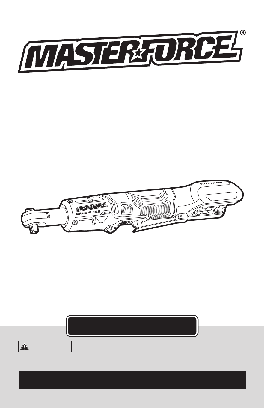
3/8” RATCHET
OPERATOR’S MANUAL
CAUTION:
To Reduce the Risk of Injury, User Must
Read and Understand the Operator’s Manual. Save These
Instructions For Future Reference.
For questions / comments, technical assistance or repair parts –
Please Call Toll Free: 1-866-917-4374 (M-F 8:30am-5:00pm EST).

TABLE OF CONTENTS
Safety Symbols ......................................................... Page 2
Safety Instructions ...................................................... Page 3
Overview/Specifications ................................................. Page 8
Assembly ............................................................. Page 9
Operation ............................................................. Page 9
Maintenance .......................................................... Page 12
Troubleshooting ....................................................... Page 13
Parts List ............................................................. Page 14
Schematic Drawing .................................................... Page 14
Warranty .............................................................Page 18
Page 2
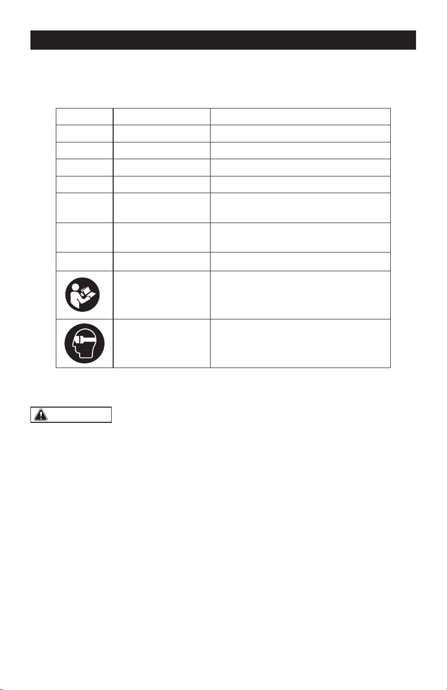
SAFETY SYMBOLS
Some of these following symbols may be used on this tool. Please study them and learn their
meaning. Proper interpretation of these symbols will allow you to operate the tool better and
more safely.
Symbol
Name
Designation / Explanation
V Volts Voltage
n
0
No-load speed Rotational speed at no load
ft-lb Pound-foot Torque
N m Newton meter Torque
RPM
Revolutions Per
Minute
Rotational speed
…/min
Revolutions or
Strokes per Minute
Revolutions, strokes, surface speed
orbits, etc., per minute
�
or d.c.
Direct current Type of characteristic of current
Read instruction
manual
To reduce the risk of injury, user must
read instruction manual.
Wear eye protection
symbol
To reduce the risk of injury, always wear
eye protection.
WARNING:
To ensure safety and reliability, all repairs should be performed by a
qualied service technician.
Page 3
SAFETY INSTRUCTIONS
The purpose of safety symbols is to attract your attention to possible dangers. The safety
symbols, and the explanations with them, deserve your careful attention and understand-
ing. The symbol warnings do not, by themselves, eliminate any danger. The instructions and
warnings they give are no substitutes for proper accident prevention measures.
WARNING:
Be sure to read and understand all safety instructions in this manual,
including all safety alert symbols such as “DANGER”, “WARNING” and “CAUTION” before
using this tool. Failure to follow all instructions listed below may result in electric shock,
re, and/or serious personal injury.
SYMBOL MEANING
SAFETY ALERT SYMBOL: Indicates DANGER, WARNING, OR CAUTION. May be used
in conjunction with other symbols or pictographs.
DANGER:
Indicates an imminently hazardous situation, which, if not avoided, will
result in death or serious injury.
WARNING:
Indicates a potentially hazardous situation, which, if not avoided,
could result in death or serious injury.
CAUTION:
Indicates a potentially hazardous situation, which, if not avoided, could
result in minor or moderate injury.
NOTICE: (Without Safety Alert Symbol) Indicates a situation that may result in property
damage.
SAVE THESE INSTRUCTIONS!

Page 4
SAFETY INSTRUCTIONS
GENERAL POWER TOOL
SAFETY WARNINGS
WARNING:
Read all safety
warnings, instructions, illustrations and
specications provided with this power
tool. Failure to follow all instructions listed
below may result in electric shock, fire and/
or serious injury.
SAVE ALL WARNINGS AND INSTRUCTIONS
FOR FUTURE REFERENCE.
The term “power tool” in the warnings refers
to your mains-operated (corded) power tool
or battery-operated (cordless) power tool.
WORK AREA SAFETY
1. Keep work area clean and well lit.
Cluttered or dark areas invite accidents.
2. Do not operate power tools in explosive
atmospheres, such as in the presence of
ammable liquids, gases or dust. Power
tools create sparks which may ignite the
dust or fumes.
3. Keep children and bystanders away
while operating a power tool. Distractions
can cause you to lose control.
ELECTRICAL SAFETY
1. Power tool plugs must match the
outlet. Never modify the plug in any way.
Do not use any adapter plugs with earthed
(grounded) power tools. Unmodified plugs
and matching outlets will reduce risk of
electric shock.
2. Avoid body contact with earthed
or grounded surfaces, such as pipes,
radiators, ranges and refrigerators. There
is an increased risk of electric shock if your
body is earthed or grounded.
3. Do not expose power tools to rain or
wet conditions. Water entering a power tool
will increase the risk of electric shock.
4. Do not abuse the cord. Never use the
cord for carrying, pulling or unplugging the
power tool. Keep cord away from heat, oil,
sharp edges or moving parts. Damaged or
entangled cords increase the risk of electric
shock.
5. When operating a power tool outdoors,
use an extension cord suitable for outdoor
use. Use of a cord suitable for outdoor use
reduces the risk of electric shock.
6. If operating a power tool in a damp
location is unavoidable, use a ground fault
circuit interrupter (GFCI) protected supply.
Use of an GFCI reduces the risk of electric
shock.
PERSONAL SAFETY
1. Stay alert, watch what you are doing
and use common sense when operating a
power tool. Do not use a power tool while
you are tired or under the inuence of
drugs, alcohol or medication. A moment of
inattention while operating power tools may
result in serious personal injury.
2. Use personal protective equipment.
Always wear eye protection. Protective
equipment such as a dust mask, non-skid
safety shoes, hard hat or hearing protection
used for appropriate conditions will reduce
personal injuries.
3. Prevent unintentional starting. Ensure
the switch is in the off-position before
connecting to power source and/or battery
pack, picking up or carrying the tool.
Carrying power tools with your finger on the
switch or energizing power tools that have
the switch on invites accidents.
4. Remove any adjusting key or wrench
before turning the power tool on. A wrench
or a key left attached to a rotating part of the
power tool may result in personal injury.
5. Do not overreach. Keep proper footing
and balance at all times. This enables better
control of the power tool in unexpected
situations.

Page 5
SAFETY INSTRUCTIONS
6. Dress properly. Do not wear loose
clothing or jewelry. Keep your hair and
clothing away from moving parts. Loose
clothes, jewelry or long hair can be caught
in moving parts.
7. If devices are provided for the
connection of dust extraction and
collection facilities, ensure these are
connected and properly used. Use of dust
collection can reduce dust-related hazards.
8. Do not let familiarity gained from
frequent use of tools allow you to become
complacent and ignore tool safety
principles. A careless action can cause
severe injury within a fraction of a second.
POWER TOOL USE AND CARE
1. Do not force the power tool. Use the
correct power tool for your application. The
correct power tool will do the job better and
safer at the rate for which it was designed.
2. Do not use the power tool if the switch
does not turn it on and off. Any power tool
that cannot be controlled with the switch is
dangerous and must be repaired.
3. Disconnect the plug from the power
source and/or remove the battery pack,
if detachable, from the power tool before
making any adjustments, changing
accessories, or storing power tools. Such
preventive safety measures reduce the risk
of starting the power tool accidentally.
4. Store idle power tools out of the reach
of children and do not allow persons
unfamiliar with the power tool or these
instructions to operate the power tool.
Power tools are dangerous in the hands of
untrained users.
5. Maintain power tools and accessories.
Check for misalignment or binding of
moving parts, breakage of parts and
any other condition that may affect the
power tool’s operation. If damaged, have
the power tool repaired before use. Many
accidents are caused by poorly maintained
power tools.
6. Keep cutting tools sharp and clean.
Properly maintained cutting tools with sharp
cutting edges are less likely to bind and are
easier to control.
7. Use the power tool, accessories
and tool bits etc. in accordance with
these instructions, taking into account
the working conditions and the work to
be performed. Use of the power tool for
operations different from those intended
could result in a hazardous situation.
8. Keep handles and grasping surfaces
dry, clean and free from oil and grease.
Slippery handles and grasping surfaces do
not allow for safe handling and control of the
tool in unexpected situations.
BATTERY TOOL USE AND CARE
1. Recharge only with the charger
specied by the manufacturer. A charger
that is suitable for one type of battery pack
may create a risk of fire when used with
another battery pack.
2. Use power tools only with specically
designated battery packs. Use of any other
battery packs may create a risk of injury and
fire.
3. When battery pack is not in use, keep
it away from other metal objects, like
paper clips, coins, keys, nails, screws or
other small metal objects, that can make
a connection from one terminal to another.
Shorting the battery terminals together may
cause burns or a fire.
4. Under abusive conditions, liquid may
be ejected from the battery; avoid contact.
If contact accidentally occurs, ush with
water. If liquid contacts eyes, additionally
seek medical help. Liquid ejected from the
battery may cause irritation or burns.
5. Do not use a battery pack or tool that
is damaged or modied. Damaged or
modified batteries may exhibit unpredictable
behavior resulting in fire, explosion or risk of
injury.
Page 6
SAFETY INSTRUCTIONS
6. Do not expose a battery pack or tool
to re or excessive temperature. Exposure
to fire or temperature above 130 °C (265 °F)
may cause explosion.
7. Follow all charging instructions and
do not charge the battery pack or tool
outside the temperature range specied
in the instructions. Charging improperly or
at temperatures outside the specified range
may damage the battery and increase the
risk of fire.
SERVICE
1. Have your power tool serviced by a
qualied repair person using only identical
replacement parts. This will ensure that the
safety of the power tool is maintained.
2. Never service damaged battery
packs. Service of battery packs should
only be performed by the manufacturer or
authorized service providers.
SPECIFIC SAFETY WARNINGS
FOR RATCHET
1. Hold the power tool by insulated
gripping surfaces, when performing an
operation where the fastener may contact
hidden wiring. Fasteners contacting a “live”
wire may make exposed metal parts of the
power tool “live” and could give the operator
an electric shock.
IMPORTANT SAFETY
INSTRUCTIONS
1. To reduce the risk of electric shock or
damage to the chargers and batteries, use
only with the MASTERFORCE
®
20V battery
packs and chargers listed.
Battery pack Charger
252-8031 (2.0Ah)
252-8003 (2.5Ah)
252-8034 (4.0Ah)
252-8013 (4.0Ah)
252-8005 (5.0Ah)
252-8014 (8.0Ah)
252-8025
252-8037
252-8026
252-8043
2. For best results, your battery and tool
should be stored, charged and used in a
location where the temperature is more
than 41°F (5 °C) but less than 104°F (40 °C).
Do not store outside or in vehicles.
NOTE: The battery pack and charger
manuals are provided separately. They
include specific safety rules and operating
instructions. Please refer to the battery pack
and charger manuals for safety rules and
detailed operating instructions.
DANGER:
People with electronic
devices, such as pacemakers, should
consult their physician(s) before using this
product. Operation of electrical equipment
in close proximity to a heart pacemaker
could cause interference or failure of the
pacemaker.
WARNING:
Drilling, sawing,
sanding or machining wood products can
expose you to wood dust, a substance
known to the State of California to cause
cancer. Avoid inhaling wood dust or use
a dust mask or other safeguards for
personal protection. For more information
go to www.P65Warnings.ca.gov/wood.

Page 7
WARNING:
• Some dust created by power sanding,
sawing, grinding, drilling, and other
construction activities contains chemicals
known to the state of California to cause
cancer, birth defects, or other reproductive
harm. Some examples of these chemicals
are:
– Lead from lead-based paints
– Crystalline silica from bricks, cement, and
other masonry products
– Arsenic and chromium from chemically-
treated lumber
• Your risk from these exposures varies,
depending upon how often you do this type
of work. To reduce your exposure to these
chemicals:
– Work in a well-ventilated area.
– Work with approved safety equipment,
such as dust masks that are specially
designed to filter out microscopic
particles.
– Avoid prolonged contact with dust from
power sanding, sawing, grinding, drilling,
and other construction activities. Wear
protective clothing and wash exposed
areas with soap and water. Allowing dust
to get into your mouth or eyes or to lie
on the skin may promote absorption of
harmful chemicals.
SAVE THESE INSTRUCTIONS!
SAFETY INSTRUCTIONS
Page 8
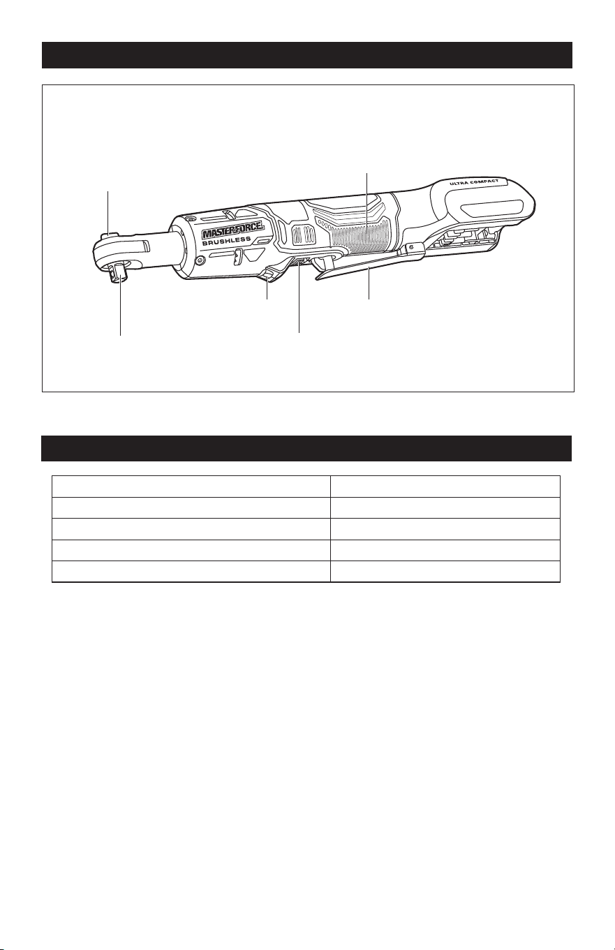
OVERVIEW
LED Work Light
Paddle Switch
Handle
Lock-off Button
3/8’’ Square
Drive Anvil
Forward/Reverse
Selector
SPECIFICATIONS
Rated Voltage 20 V d.c.
No-load Speed 0 – 400 /min (RPM)
Square Anvil Size 3/8” (9.5 mm)
Maximum Output Torque (in forward rotation) 40 ft-lb (54 N m)
Weight (without battery) 1 lbs. 16 oz. (0.9 kg)
Page 9
OPERATION
WARNING:
If any part is broken or
missing, DO NOT attach the battery pack
or operate the tool until the broken or
missing part is replaced. Failure to do so
could result in possible serious injury.
WARNING:
Do not attempt to
modify this tool or create accessories not
recommended for use with this tool. Any
such alteration or modication is misuse
and could result in a hazardous condition
leading to possible serious injury.
WARNING:
Your tool should
never be connected to the battery pack
when you are assembling parts, making
adjustments, cleaning, or when it is not in
use. Disconnecting the tool will prevent
accidental starting, which could cause
serious personal injury.
ASSEMBLY
PACKING LIST
– Ratchet
– Instruction manual
UNPACKING
1. Carefully remove the tool and any
accessories from the carton. Make sure
that all items listed in the packing list are
included.
2. Inspect the tool carefully to make sure
that no breakage or damage occurred
during shipping.
3. Do not discard the packing material
until you have carefully inspected and
satisfactorily operated the tool.
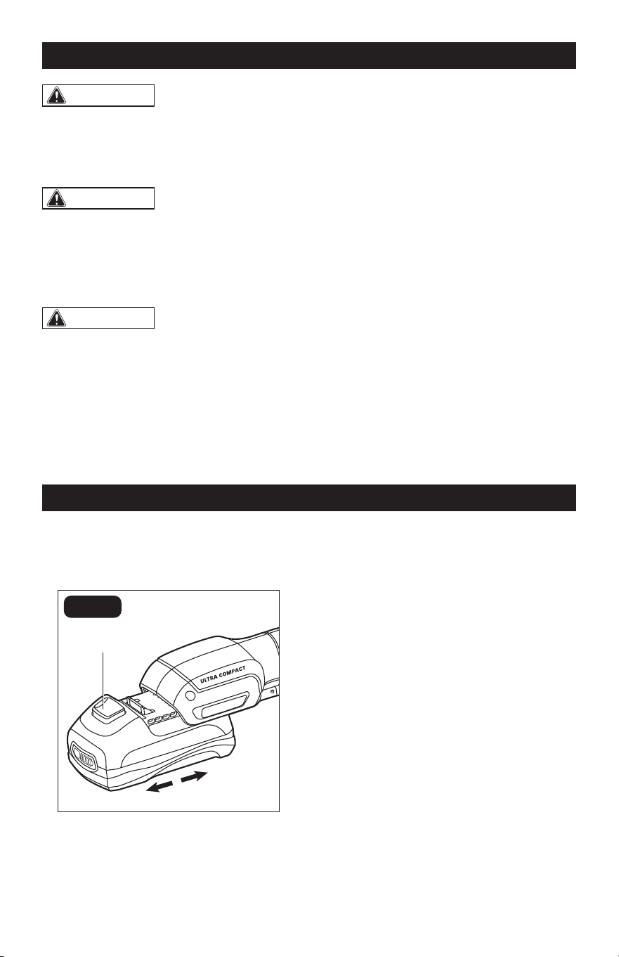
ATTACHING BATTERY PACK
(FIG. 1)
FIG. 1
Battery-Release
Button
Attach
Detach
1. Lock the paddle switch in the OFF
position (refer to the section “LOCK-
OFF BUTTON”).
2. Align the raised ribs on the battery pack
with the grooves in the tool, and then
slide the battery pack onto the tool.
3. Make sure that the latch on the battery
pack snaps into place, and that the
battery pack is attached securely to the
tool before beginning operation.
DETACHING BATTERY PACK
(FIG. 1)
1. Lock the paddle switch in the OFF
position.
2. Depress the battery-release button,
located on the front of the battery pack,
to release the battery pack.
3. Pull the battery pack out and remove it
from the tool.
Page 10
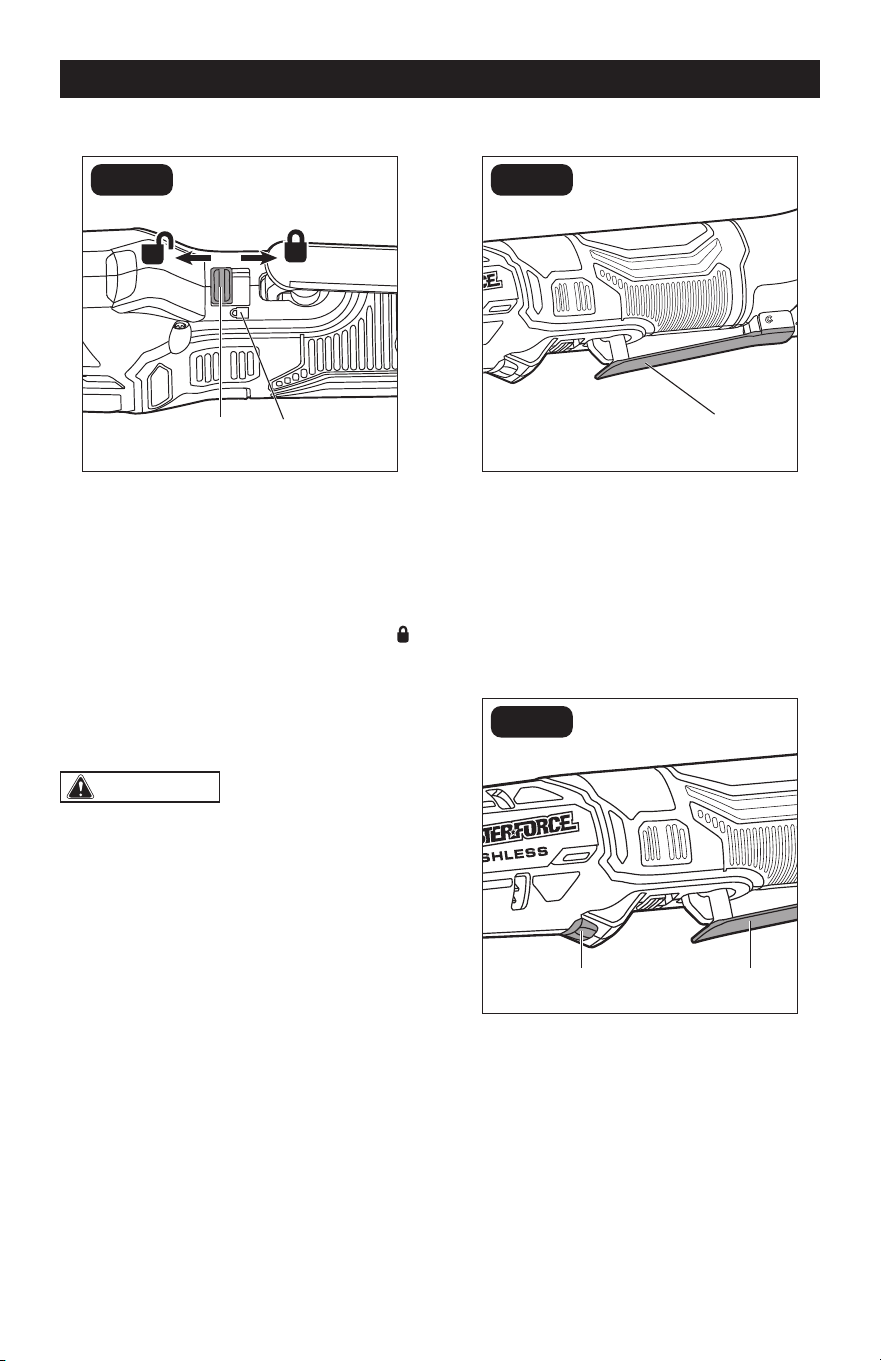
LOCK-OFF BUTTON (FIG. 2)
FIG. 2
Lock-off Button Mark
Your tool is equipped with a lock-off button,
a safety feature, to prevent the tool from be-
ing activated unintentionally.
To lock the paddle switch in the OFF posi-
tion
Push the lock-off button to the locked (
)
position until you hear a “click”.
To unlock the paddle switch
Push the lock-off button to the unlocked po-
sition until you hear a “click”.
WARNING:
Battery tools are
always in operating condition. ALWAYS
lock the paddle switch in the OFF position
and remove the battery pack when the
tool is not in use, or before making any
assembly, adjustments or changing
accessories.
PADDLE SWITCH (FIG. 3)
FIG. 3
Paddle Switch
Your tool is equipped with a paddle switch.
The tool can be turned “ON” or “OFF” by de-
pressing or releasing the switch.
The paddle switch delivers higher speed
with increased paddle pressure and lower
speed with decreased paddle pressure.
LED WORK LIGHT (FIG. 4)
FIG. 4
Paddle SwitchLED Work Light
The LED work light, located on the under-
side of the tool, will illuminate when the pad-
dle switch is depressed without turning the
tool on. This provides additional illumination
of the surface of the workpiece.
The LED work light will turn off approximate-
ly 10 seconds after the switch is released.
OPERATION
Page 11
OPERATION
Additionally, the LED work light will flash to
communicate the following situations:
– The LED work light will flash rapidly when
the tool and/or battery pack becomes
overloaded or too hot and the internal
sensors will turn the tool off. Rest the tool
for a while or place the tool and battery
pack separately under air flow for cooling.
– The LED work light will flash slowly to
indicate that the battery charge is very
low. Charge the battery pack.
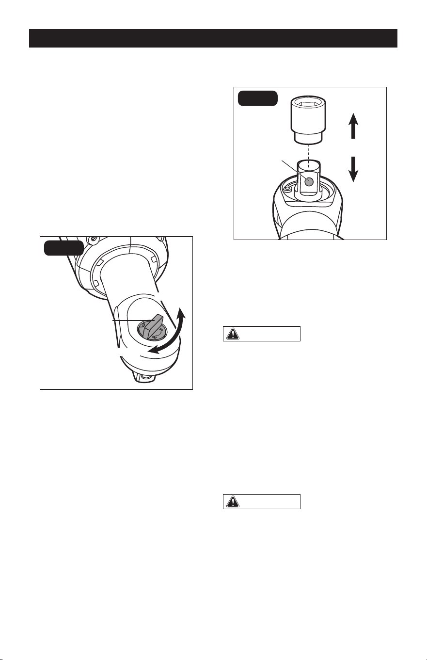
FORWARD/REVERSE SELECTOR
(FIG. 5)
FIG. 5
Forward/Reverse
Selector
Reverse
Forward
The direction of the anvil rotation is revers-
ible and is controlled by the forward/reverse
selector located above the anvil.
1. For forward (clockwise) rotation to
tighten bolts/nuts, rotate the forward/
reverse selector COUNTERCLOCKWISE.
2. For reverse (counterclockwise) rotation
to loosen bolts/nuts, rotate the forward/
reverse selector CLOCKWISE.
3. Make sure that the forward/reverse
selector is fully turned with an audible
click. Check the direction of rotation
before use.
NOTE: To prevent damage, always allow
the tool to come to a complete stop before
changing the direction of rotation.
TO INSTALL AND REMOVE
SOCKET (FIG. 6)
FIG. 6
Dent Pin
1. Remove the battery pack.
2. To install a 3/8” socket (not included),
push it onto the square anvil until the
detent pin locks it into place.
3. To remove the socket, pull it away from
the anvil.
WARNING:
• Only use sockets designed for ratchets.
Sockets not designed for ratchets could
break and result in user injury.
• Inspect sockets prior to use to ensure
that they have no cracks or other visible
damage.
• The socket may be hot after prolonged
use. Use protective gloves when removing
the socket from the tool, or rst allow it to
cool down.
USING THE RATCHET
WARNING:
Battery tools are
always in operating condition. Therefore,
always remove the battery pack when the
tool is not in use or when carrying it at
your side.
The proper fastening torque may differ, de-
pending on the type or size of the bolt, the
material of the workpiece to be fastened,
etc. Before starting your job, always perform
Page 12
OPERATION
a test operation to determine the proper fas-
tening time for your bolt or nut.
1. Check the forward/reverse selector for
the correct directional setting (forward or
reverse).
2. Hold the tool firmly and place the socket
over the bolt or nut.
3. Push the lock-off button to the unlocked
position and then depress the paddle
switch to turn the ratchet ON. The
paddle switch delivers higher speed with
increased paddle pressure and lower
speed with decreased paddle pressure.
4. Fasten the bolt or nut to the proper
torque. After fastening, the ratchet
wrench will enter a protection mode and
shut down.
5. When using a ratchet to remove bolts,
loosen the bolts a bit manually with the
ratchet first and then depress the paddle
switch. If the paddle switch is depressed
directly, the ratchet will enter a protection
mode and shut down instead of
loosening.
6. To turn the ratchet OFF, release the
paddle switch.
NOTICE: Hold the tool straight along the
axis of the bolt or nut.
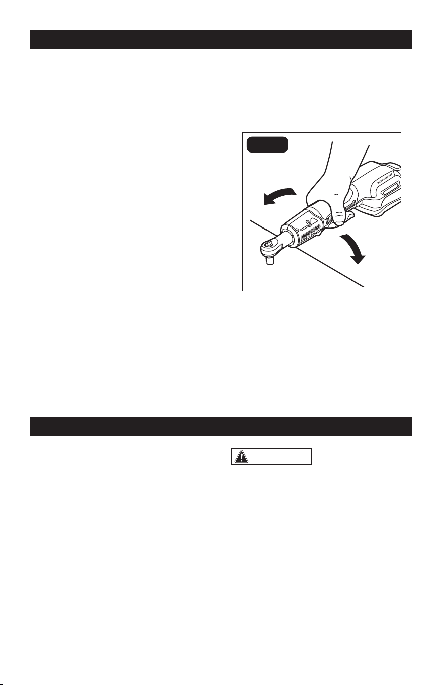
USING AS A HAND TOOL (FIG. 7)
R
F
FIG. 7
The ratchet can be used as a hand tool to
loosen stiff/rusty bolts or nuts as shown in
FIG. 7. It is not recommended to use the
ratchet as a hand tool to tighten fasteners.
NOTICE: Be careful when using the ratchet
as a hand tool. Excessive force applied to
the tool may damage the tool head.
1. Check for damaged, missing, or worn
parts.
2. Check for loose screws, misalignment
or binding of moving parts, or any other
condition that may affect the operation.
3. If abnormal vibration or noise occurs,
turn the tool off immediately and have
the problem corrected before further
use.
4. For safe and proper operation, always
keep the tool and its ventilation slots
clean. Always use only a soft, dry
cloth to clean your ratchet; never use
detergent or alcohol.
5. Store the tool indoors in a place that
is inaccessible to children. Keep away
from corrosive agents.
MAINTENANCE
WARNING:
• When servicing, use only identical
replacement parts. Use of any other
parts may create a hazard or cause
product damage.
• To avoid serious personal injury, always
remove the battery pack from the
product when cleaning or performing
any maintenance.
• To ensure safety and reliability, all
repairs should be performed by a
qualied service technician.

Page 13
TROUBLESHOOTING
PROBLEM POSSIBLE CAUSE SOLUTION
The tool fails to start when the
paddle switch is depressed.
Battery pack charge is
depleted.
Charge the battery pack.
The socket cannot be
installed.
The socket does not fit
the square anvil.
Use a suitable adapter or a
socket that matches the size
of the square anvil.
Motor overheating.
Cooling vents are
obstructed.
Clean and clear vents. Do
not cover vents with hand
during operation.
The LED work light flashes
rapidly.
The tool has stopped
working to protect internal
electronics.
Release the paddle switch,
wait for the tool to cool
down, and then start the tool
again.
The LED work light flashes
slowly.
Low battery pack
capacity.
Charge the battery pack.
Page 14
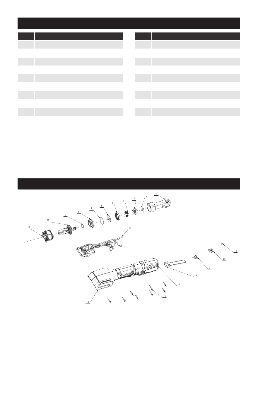
PARTS LIST
SCHEMATIC DRAWING
No. Part Name
1 Ratchet Assembly
2 Plain Washer
3 Planet Carrier
4 Planet Gear
5 Gear Ring
6 Plain Washer
7 O Ring
8 Rear Gear Case
9 O Ring
10 Rotor Assembly
No. Part Name
11 Stator
12 Main Electric Assembly
13 L R Housing Set
14 Hexagon Lobular Screw
15 Hexalobular Socket Screw
16 Switch Trigger
17 LED Cover
18 Lock Button
19 Rubber Column

Page 15
NOTES

Page 16
NOTES

Page 17
NOTES

3/8” Ratchet

06/2024
© 2023 Menard, Inc., Eau Claire, WI 54703