
Form No. 3463-887 Rev C
Power Max
®
e24 60V Snowthrower
Model No. 39924 —Serial No. 415000000 and Up
Model No. 39925 —Serial No. 400000000 and Up
Operator's Manual
Introduction
This machine is intended to be used by residential
homeowners. It is designed primarily for removing
snow from paved surfaces, such as driveways and
sidewalks, and other surfaces for traf c on residential
or commercial properties. It is not designed for
removing materials other than snow . It is designed to
use Flex-Force 60V lithium-ion battery packs. These
battery packs are designed to be charged only by
Flex-Force 60V lithium-ion battery chargers. Using
this product for purposes other than its intended use
could prove dangerous to you and bystanders.
Read this information carefully to learn how to operate
and maintain your product properly and to avoid
injury and product damage. Y ou are responsible for
operating the product properly and safely .
V isit www .T oro.com for product safety and operation
training materials, accessory information, help nding
a dealer , or to register your product.
Whenever you need service, genuine T oro parts, or
additional information, contact an Authorized Service
Dealer or T oro Customer Service and have the model
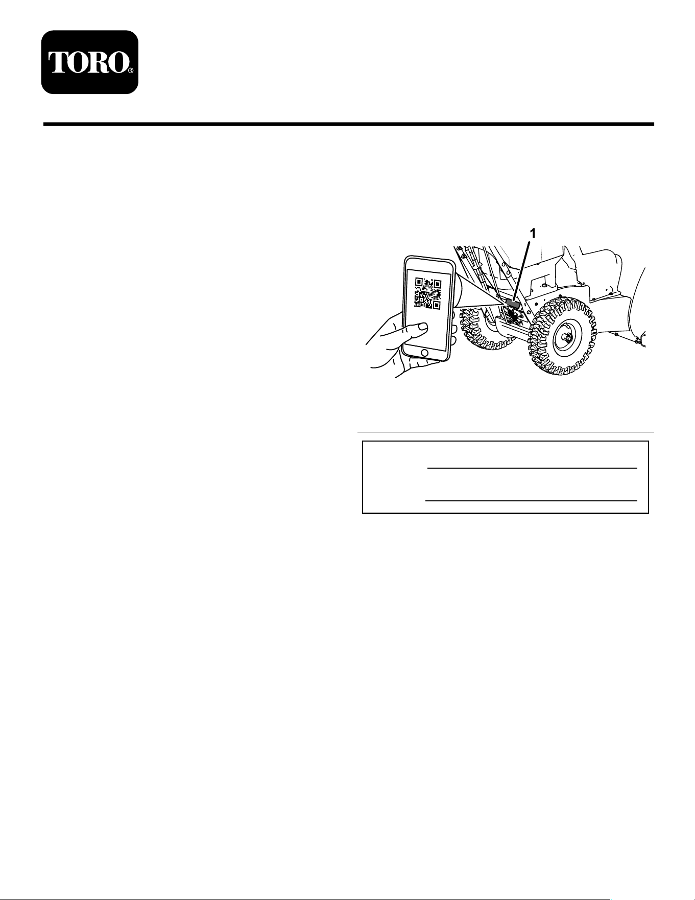
and serial numbers of your product ready . Figure 1
identies the location of the model and serial numbers
on the product. W rite the numbers in the space
provided.
Important: W ith your mobile device, you can
scan the QR code on the serial number decal (if
equipped) to access warranty , parts, and other
product information.
g397375
Figure 1
1. Model and serial number location
Model No.
Serial No.
© 2024—The T oro® Company
81 1 1 L yndale A venue South
Bloomington, MN 55420 Register at www .T oro.com.
Original Instructions (EN)
Printed in Mexico
All Rights Reserved
*3463-887*

Safety-Alert Symbol
The safety-alert symbol ( Figure 2 ) shown in this
manual and on the machine identies important safety
messages that you must follow to prevent accidents.
g000502
Figure 2
Safety-alert symbol
The safety-alert symbol appears above information
that alerts you to unsafe actions or situations and
is followed by the word DANGER , W ARNING , or
CAUTION .
DANGER indicates an imminently hazardous situation
which, if not avoided, will result in death or serious
injury .
W ARNING indicates a potentially hazardous situation
which, if not avoided, could result in death or serious
injury .
CAUTION indicates a potentially hazardous situation
which, if not avoided, may result in minor or moderate
injury .
This manual uses two other words to highlight
information. Important calls attention to special
mechanical information and Note emphasizes general
information worthy of special attention.
W ARNING
CALIFORNIA
Proposition 65 W arning
The power cord on this product contains
lead, a chemical known to the State
of California to cause birth defects
or other reproductive harm. W ash
hands after handling.
Use of this product may cause exposure
to chemicals known to the State of
California to cause cancer , birth defects,
or other reproductive harm.
Contents
Introduction . . . . . . . . . . . . . . . . . . . . . . . . . . . . . . . . . . . . . . . . . . . . . . . . . . . . . . . . . . . . . . . 1
Safety-Alert Symbol . . . . . . . . . . . . . . . . . . . . . . . . . . . . . . . . . . . . . . . . . . . . 2
Safety . . . . . . . . . . . . . . . . . . . . . . . . . . . . . . . . . . . . . . . . . . . . . . . . . . . . . . . . . . . . . . . . . . . . . . . 3
. . . . . . . . . . . . . . . . . . . . . . . . . . . . . . . . . . . . . . . . . . . . . . . . . . . . . . . . . . . . . . . . . . . . . . . . . . . 3
Safety and Instructional Decals . . . . . . . . . . . . . . . . . . . . . . . . . . 6
Setup . . . . . . . . . . . . . . . . . . . . . . . . . . . . . . . . . . . . . . . . . . . . . . . . . . . . . . . . . . . . . . . . . . . . . . . . 9
1 Mounting the Battery Charger
(Optional) . . . . . . . . . . . . . . . . . . . . . . . . . . . . . . . . . . . . . . . . . . . . . . . . . . . . . . . . 9
2 Installing the Chute . . . . . . . . . . . . . . . . . . . . . . . . . . . . . . . . . . . . . . . . . . 9
3 Installing the Upper Handle . . . . . . . . . . . . . . . . . . . . . . . . . . . . 10
4 Installing the T raction-Control Linkage . . . . . . . . . . . . 1 1
5 Installing the Chute-Control Rod . . . . . . . . . . . . . . . . . . . . . 1 1
6 Installing the Snow-Cleanout T ool . . . . . . . . . . . . . . . . . . 12
7 Checking the T ire Pressure . . . . . . . . . . . . . . . . . . . . . . . . . . . . 13
8 Checking the Skids and Scraper . . . . . . . . . . . . . . . . . . . . 14
9 Adjusting the Auger/Impeller Cable . . . . . . . . . . . . . . . . 14
10 Checking the Operation of the T raction
Drive . . . . . . . . . . . . . . . . . . . . . . . . . . . . . . . . . . . . . . . . . . . . . . . . . . . . . . . . . . . . . 14
Product Overview . . . . . . . . . . . . . . . . . . . . . . . . . . . . . . . . . . . . . . . . . . . . . . . . . . . 15
Specications . . . . . . . . . . . . . . . . . . . . . . . . . . . . . . . . . . . . . . . . . . . . . . . . . . 16
Attachments/Accessories . . . . . . . . . . . . . . . . . . . . . . . . . . . . . . . . . 16
Operation . . . . . . . . . . . . . . . . . . . . . . . . . . . . . . . . . . . . . . . . . . . . . . . . . . . . . . . . . . . . . . . . 16
Before Operation . . . . . . . . . . . . . . . . . . . . . . . . . . . . . . . . . . . . . . . . . . . . . . . . . 16
Installing the Battery Pack . . . . . . . . . . . . . . . . . . . . . . . . . . . . . . . . 16
Checking the State of Charge . . . . . . . . . . . . . . . . . . . . . . . . . . . 17
During Operation . . . . . . . . . . . . . . . . . . . . . . . . . . . . . . . . . . . . . . . . . . . . . . . . . 17
Starting the Machine . . . . . . . . . . . . . . . . . . . . . . . . . . . . . . . . . . . . . . . . . 17
Activating ECO Mode . . . . . . . . . . . . . . . . . . . . . . . . . . . . . . . . . . . . . . . 17
Charging the Battery Pack . . . . . . . . . . . . . . . . . . . . . . . . . . . . . . . . 18
Operating the T raction Drive . . . . . . . . . . . . . . . . . . . . . . . . . . . . . 19
Operating the Speed Selector . . . . . . . . . . . . . . . . . . . . . . . . . . . 19
Operating the Auger/Impeller Drive . . . . . . . . . . . . . . . . . . . 20
Operating the Quick Stick® . . . . . . . . . . . . . . . . . . . . . . . . . . . . . . . 21
Clearing a Clogged Discharge Chute . . . . . . . . . . . . . . . . 21
Operating T ips . . . . . . . . . . . . . . . . . . . . . . . . . . . . . . . . . . . . . . . . . . . . . . . . . 22
After Operation . . . . . . . . . . . . . . . . . . . . . . . . . . . . . . . . . . . . . . . . . . . . . . . . . . . . 23
Shutting Of f the Machine . . . . . . . . . . . . . . . . . . . . . . . . . . . . . . . . . . 23
Removing the Battery Pack from the
Machine . . . . . . . . . . . . . . . . . . . . . . . . . . . . . . . . . . . . . . . . . . . . . . . . . . . . . . . . 23
Preventing Freeze-up after Use . . . . . . . . . . . . . . . . . . . . . . . . 23
Maintenance . . . . . . . . . . . . . . . . . . . . . . . . . . . . . . . . . . . . . . . . . . . . . . . . . . . . . . . . . . . 24
Recommended Maintenance Schedule(s) . . . . . . . . . . . 24
Preparing for Maintenance . . . . . . . . . . . . . . . . . . . . . . . . . . . . . . . 24
Checking and Adjusting the Skids and
Scraper . . . . . . . . . . . . . . . . . . . . . . . . . . . . . . . . . . . . . . . . . . . . . . . . . . . . . . . . . 24
Checking and Adjusting the T raction
Cable . . . . . . . . . . . . . . . . . . . . . . . . . . . . . . . . . . . . . . . . . . . . . . . . . . . . . . . . . . . . 25
Checking and Adjusting the Auger/Impeller
Cable . . . . . . . . . . . . . . . . . . . . . . . . . . . . . . . . . . . . . . . . . . . . . . . . . . . . . . . . . . . . 26
Checking the Auger-Gearbox-Oil Level . . . . . . . . . . . . . 27
Lubricating the Hex Shaft . . . . . . . . . . . . . . . . . . . . . . . . . . . . . . . . . . 27
Replacing the Drive Belts . . . . . . . . . . . . . . . . . . . . . . . . . . . . . . . . . . 28
Storage . . . . . . . . . . . . . . . . . . . . . . . . . . . . . . . . . . . . . . . . . . . . . . . . . . . . . . . . . . . . . . . . . . . 29
Storing the Machine . . . . . . . . . . . . . . . . . . . . . . . . . . . . . . . . . . . . . . . . . . 29
T roubleshooting . . . . . . . . . . . . . . . . . . . . . . . . . . . . . . . . . . . . . . . . . . . . . . . . . . . . . . 30
2

Safety
IMPORT ANT SAFETY
INSTRUCTIONS
W ARNING
When using an electric machine, always
read and follow basic safety warnings and
instructions to reduce the risk of re, electric
shock, or injury , including the following:
Read All Instructions
I. T raining
1. The operator of the machine is responsible for
any accidents or hazards occurring to others or
their property .
2. Read and understand the contents of this
Operator ’ s Manual before you start the machine.
Ensure that everyone using this machine knows
how to use it, knows how to shut it of f quickly ,
and understands the warnings.
3. Do not allow children to use or play with the
machine, battery pack, or the battery charger;
local regulations may restrict the age of the
operator .
4. Do not allow children or untrained people to
operate or service this device. Allow only people
who are responsible, trained, familiar with the
instructions, and physically capable to operate
or service the device.
5. Before using the machine, battery pack, and
battery charger , read all the instructions and
cautionary markings on these products.
6. Become familiar with the controls and proper
use of the machine, battery pack, and battery
charger .
II. Preparation
1. Keep bystanders and children out of the
operating area.
2. Never allow children to operate the machine.
3. Do not operate the machine without all guards
and other safety devices in place and functioning
properly on the machine.
4. Inspect the area where you will use the machine
and remove all objects that could interfere with
the operation of the machine or that the machine
could throw .
5. Use only the battery pack specied by T oro.
Using other accessories and attachments may
increase the risk of injury and re.
6. Plugging the battery charger into an outlet that
is not 120V can cause a re or electric shock.
Do not plug the battery charger into an outlet
other than 120V .
7. Do not use a damaged or modied battery
pack or battery charger , which may exhibit
unpredictable behavior that results in re,
explosion, or risk of injury .
8. If the supply cord to the battery charger is
damaged, contact an Authorized Service Dealer
to replace it.
9. Charge the battery pack with only the battery
charger specied by T oro. A charger suitable for
1 type of battery pack may create a risk of re
when used with another battery pack.
10. Charge the battery pack in a well-ventilated area
only .
1 1. Follow all charging instructions and do
not charge the battery pack outside of the
temperature range specied in the instructions.
Otherwise, you may damage the battery pack
and increase the risk of re.
12. Dress properly—W ear appropriate clothing,
including eye protection; long pants; substantial,
slip-resistant rubber boots; and hearing
protection. T ie back long hair and do not wear
loose clothing or loose jewelry that can get
caught in moving parts.
3

III. Operation
1. Contact with the moving rotor will cause serious
injury . Keep your hands and feet away from all
moving parts of the machine. Keep clear of any
discharge opening.
2. Stay behind the handles and away from the
discharge opening while operating the machine.
3. Using this machine for purposes other than its
intended use could prove dangerous to you and
bystanders.
4. Prevent unintentional starting—Ensure that the
electric-start key is removed from the key switch
before connecting the battery pack and handling
the machine.
5. Use your full attention while operating the
machine. Do not engage in any activity that
causes distractions; otherwise, injury or property
damage may occur .
6. Disengage all clutches and shift into neutral
before starting the machine.
7. Shut of f the machine, remove the electric-start
key , remove the battery pack from the machine,
and wait for all movement to stop before
adjusting, servicing, cleaning, or storing the
machine.
8. Remove the battery pack and electric-start
key from the machine whenever you leave it
unattended or before changing accessories.
9. Do not force the machine—Allow the machine to
do the job better and safer at the rate for which it
was designed.
10. Stay alert—W atch what you are doing and use
common sense when operating the machine.
Do not use the machine while ill, tired, or under
the inuence of alcohol or drugs.
1 1. Operate the machine only in good visibility and
appropriate weather conditions.
12. Use extreme caution when reversing or pulling
the machine toward you.
13. Keep proper footing and balance at all times,
especially on slopes. Use extreme caution when
changing directions on slopes. Do not operate
the machine on exceedingly steep slopes. W alk,
never run with the machine.
14. When not actively clearing snow , disengage
power to the auger .
15. Adjust the collector housing height to clear a
gravel or crushed-rock surface.
16. Do not direct the discharge material toward
anyone. A void discharging material against a
wall or obstruction; material may ricochet toward
you. Shut of f the machine when crossing gravel
surfaces.
17. Exercise extreme caution when operating the
machine on walks or roads. Stay alert for hidden
hazards or traf c.
18. If the machine strikes an object or starts to
vibrate, immediately shut of f the machine,
remove the key , remove the battery pack, and
wait for all movement to stop before examining
the machine for damage. Make all necessary
repairs before resuming operation.
19. Shut of f the machine whenever you leave the
operating position for any reason.
20. Shut of f the machine, remove the electric-start
key , and remove the battery pack(s) before
unclogging the machine and always use a stick
or a cleanout tool to remove the clog.
21. Shut of f the machine, remove the electric-start
key , and remove the battery pack(s) before
loading the machine for hauling.
22. Never operate the machine at high transport
speeds on slippery surfaces.
23. Under abusive conditions, the battery pack may
eject liquid; avoid contact. If you accidently
come into contact with the liquid, ush with
water . If the liquid contacts your eyes, seek
medical help. Liquid ejected from the battery
pack may cause irritation or burns.
24. Do not expose a battery pack or tool to re or
excessive temperature. Exposure to re or
temperature above 130°C (265°F) may cause
explosion.
25. CAUTION—A mistreated battery pack may
present a risk of re, explosion, or chemical
burn.
• Do not disassemble the battery pack.
• Replace the battery pack with a genuine
Flex-Force battery pack only; using another
type of battery pack may cause a re or risk
of injury .
• Keep battery packs out of the reach of
children and in the original packaging until
you are ready to use them.
4

IV . Maintenance and Storage
1. Shut of f the machine, wait for all moving parts to
stop, remove the electric-start key , and remove
the battery pack(s) from the machine before
adjusting, servicing, cleaning, or storing the
machine.
2. Do not attempt to repair the machine except as
indicated in the instructions. Have an Authorized
Service Dealer perform service on the machine
using identical replacement parts.
3. W ear gloves and eye protection when servicing
the machine.
4. When servicing the rotor , be aware that the rotor
can still move even though the power source
is of f.
5. For best performance, use only genuine T oro
replacement parts and accessories. Other
replacement parts and accessories could be
dangerous, and such use could void the product
warranty .
6. Maintain the machine—Keep handles dry , clean,
and free from oil and grease. Keep guards
in place and in working order . Use identical
replacement parts only .
7. Check all fasteners at frequent intervals for
proper tightness to ensure that the machine is in
safe working condition.
8. Check the machine for damaged parts. Check
for misaligned and binding moving parts, broken
parts, mounting, and any other condition that
may af fect its operation. Unless indicated in the
instructions, have an Authorized Service Dealer
repair or replace a damaged guard or part.
9. When the battery pack is not in use, keep it
away from metal objects such as paper clips,
coins, keys, nails, and screws that can make a
connection from 1 terminal to another . Shorting
the battery terminals may cause burns or a re.
10. When you are not using the machine, store it
indoors in a dry , secure place out of the reach
of children.
1 1. When storing the machine for more than 30
days, refer to Storage ( page 29 ) for important
information.
SA VE THESE
INSTRUCTIONS
5
Safety and Instructional Decals
Safety decals and instructions are easily visible to the operator and are located near any area
of potential danger . Replace any decal that is damaged or missing.
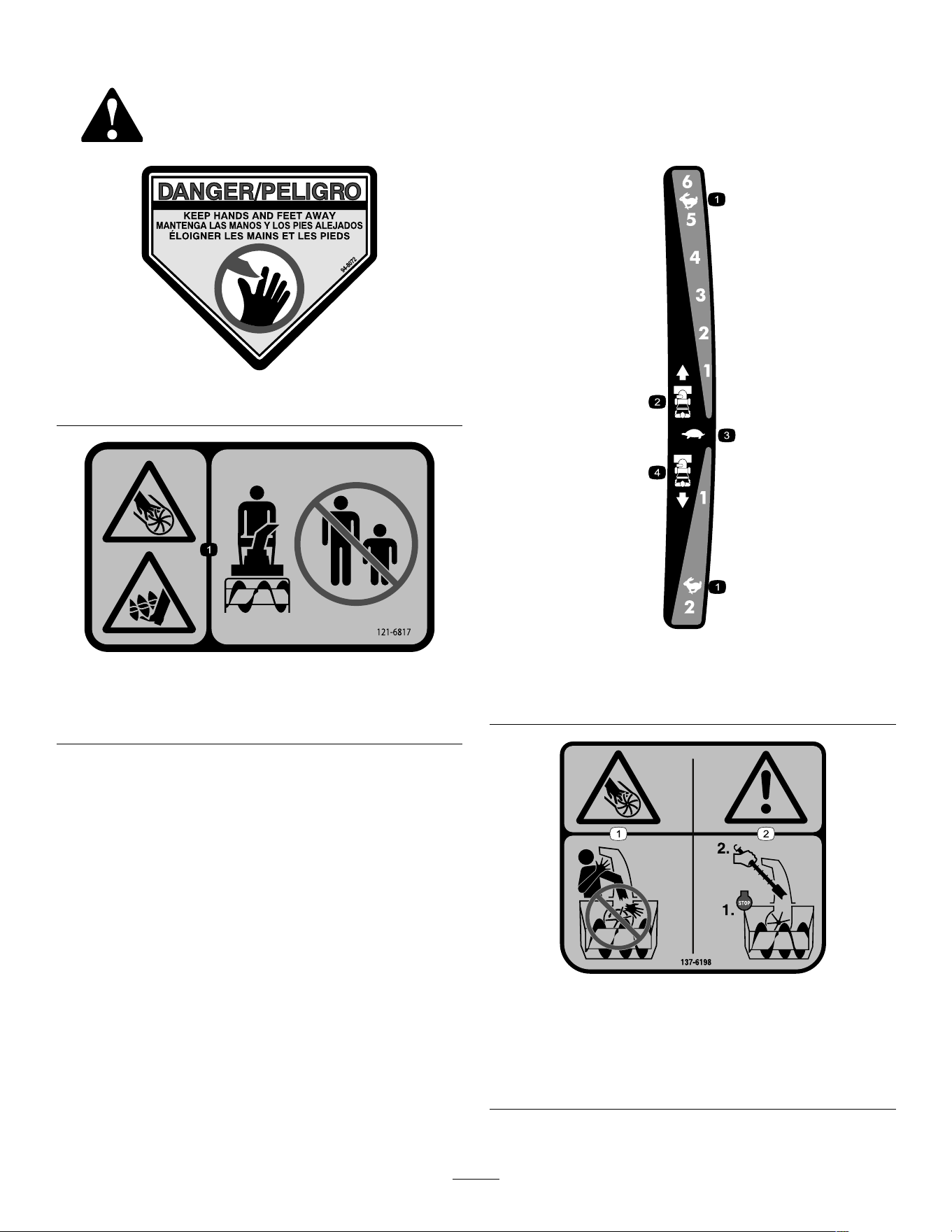
decal94-8072
94-8072
decal121-6817
121-6817
1. Cutting/dismemberment hazard of hand or foot, impeller
and auger—keep bystanders away .
decal121-6823
121-6823
1. Fast
3. Slow
2. Forward speeds 4. Reverse speeds
decal137-6198
137-6198
1. Cutting/dismemberment
hazard of the ngers or
hand, impeller—do not
place your hand in the
chute.
2. W arning—shut of f the
motor before using the tool
to clear the chute.
6
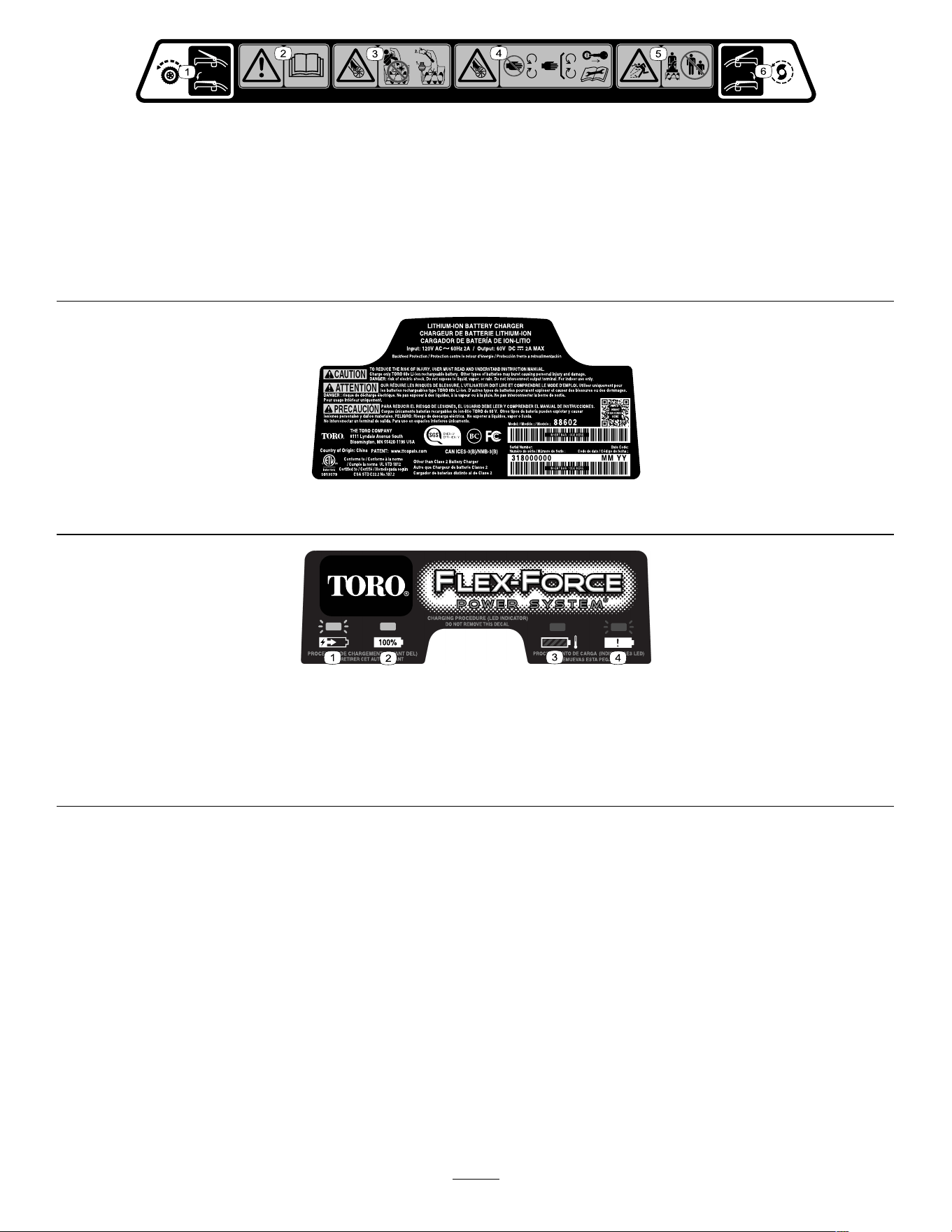
decal137-6249
137-6249
1. Squeeze the lever to engage the traction drive. 4. Cutting/dismemberment of ngers or hand, impeller
blade—keep away from moving parts; keep all guards and
shields in place; remove the key from the ignition before
servicing the machine.
2. W arning—read the Operator ’ s Manual .
5. Thrown object hazard—keep bystanders away .
3. Cutting/dismemberment of ngers or hand, impeller blade—do
not place your hand in the chute; shut of f the motor before
using the tool to clear the chute.
6. Squeeze the lever to engage the impeller .
decal137-9462
137-9462
decal137-9463
137-9463
1. The battery pack is charging.
2. The battery pack is fully charged.
3. The battery pack is over or under the appropriate temperature range.
4. Battery pack charging fault
7
decal137-9456
137-9456
1. Read the Operator ’ s
Manual .
3. Do not expose to rain.
2. Keep away from open re
or ames.
decal137-9461
137-9461
1. Battery charge status
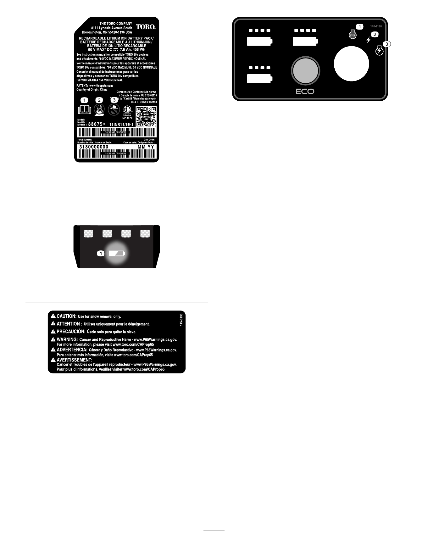
decal145-3133
145-3133
decal140-2180
140-2180
1. Of f 3. Start
2. Power
8
Setup
Important: The battery pack is not fully charged when you purchase it. Before using the machine for
the rst time, refer to Charging the Battery Pack ( page 18 ) .
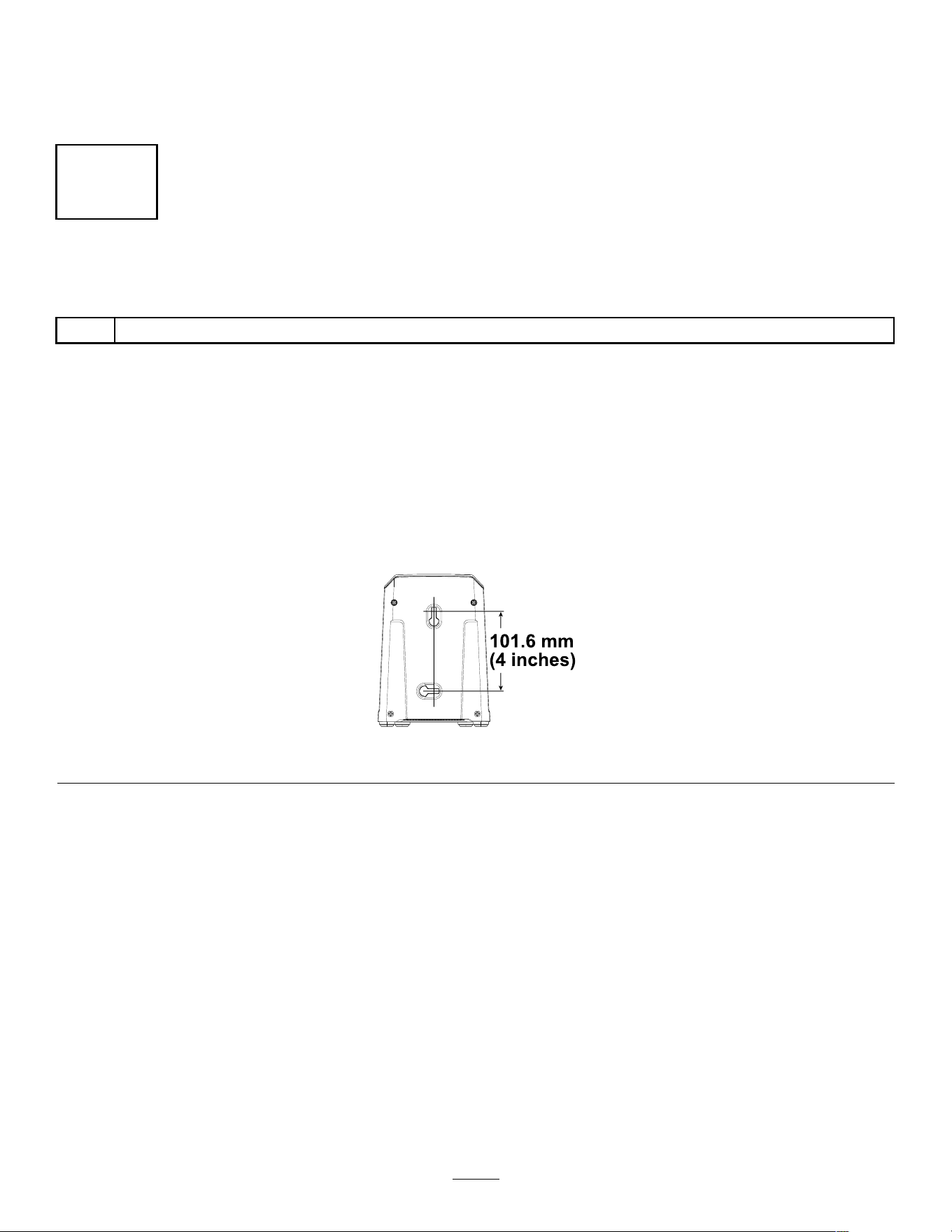
1
Mounting the Battery Charger (Optional)
Parts needed for this procedure:
2
Mounting hardware (not included)
Procedure
If desired, mount the battery charger securely on a wall using the wall-mount key holes on the back of the
charger .
Mount it indoors (such as a garage or other dry place), near a power outlet, and out of the reach of children.
Refer to Figure 3 for assistance in mounting the charger .
Slide the charger over the appropriately positioned hardware to secure the charger in place (hardware not
included).
g290534
Figure 3
9
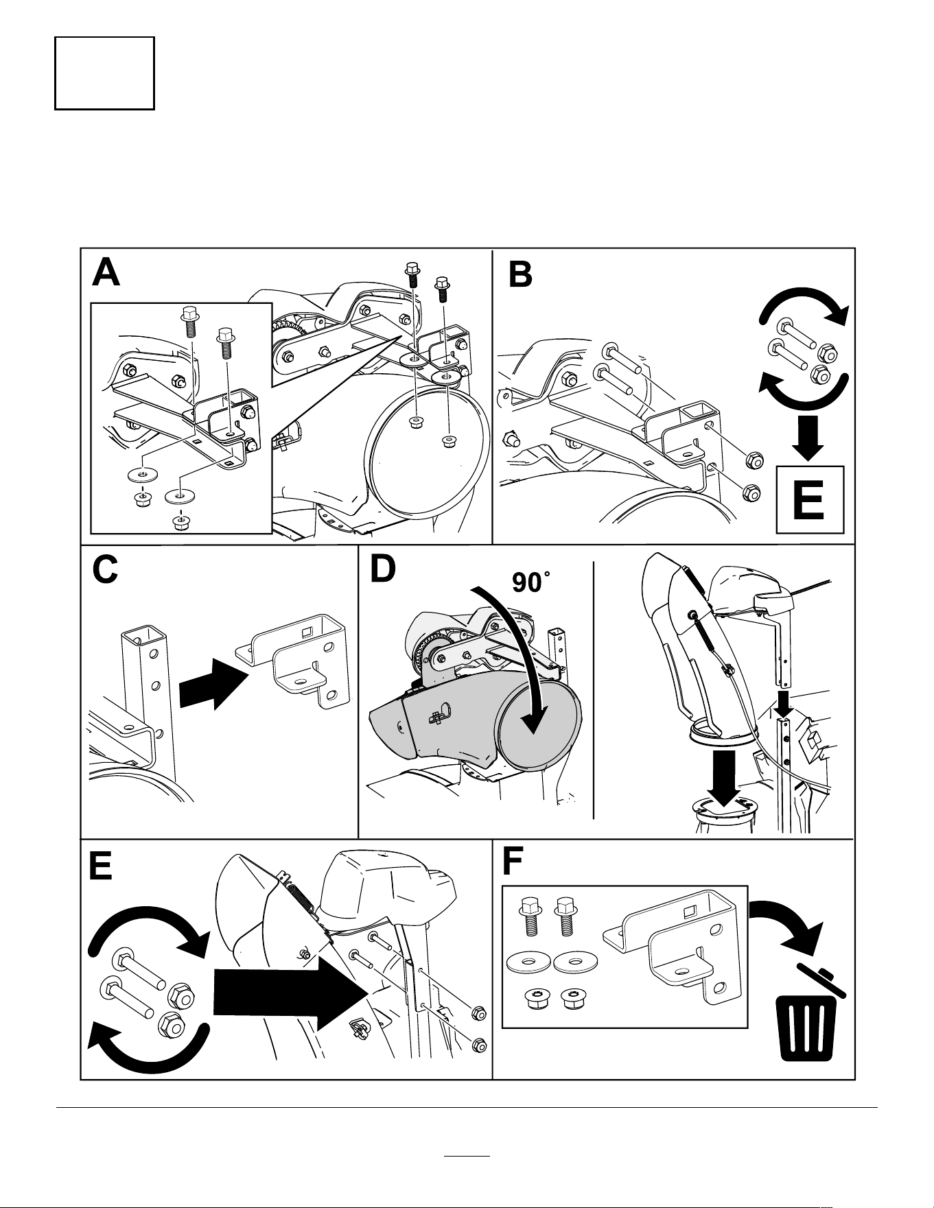
2
Installing the Chute
No Parts Required
Procedure
g461561
10
3
Installing the Upper Handle
No Parts Required
Procedure
g461559
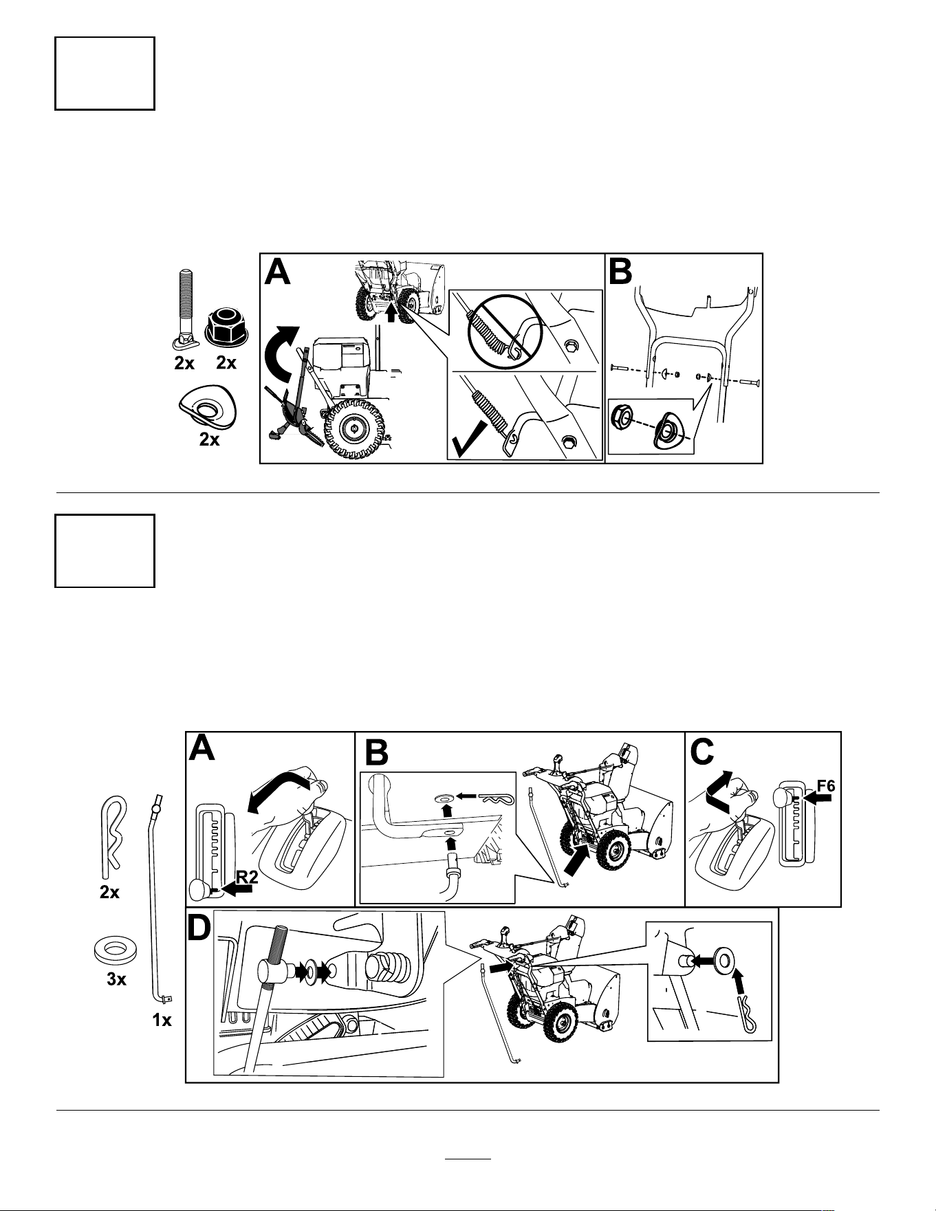
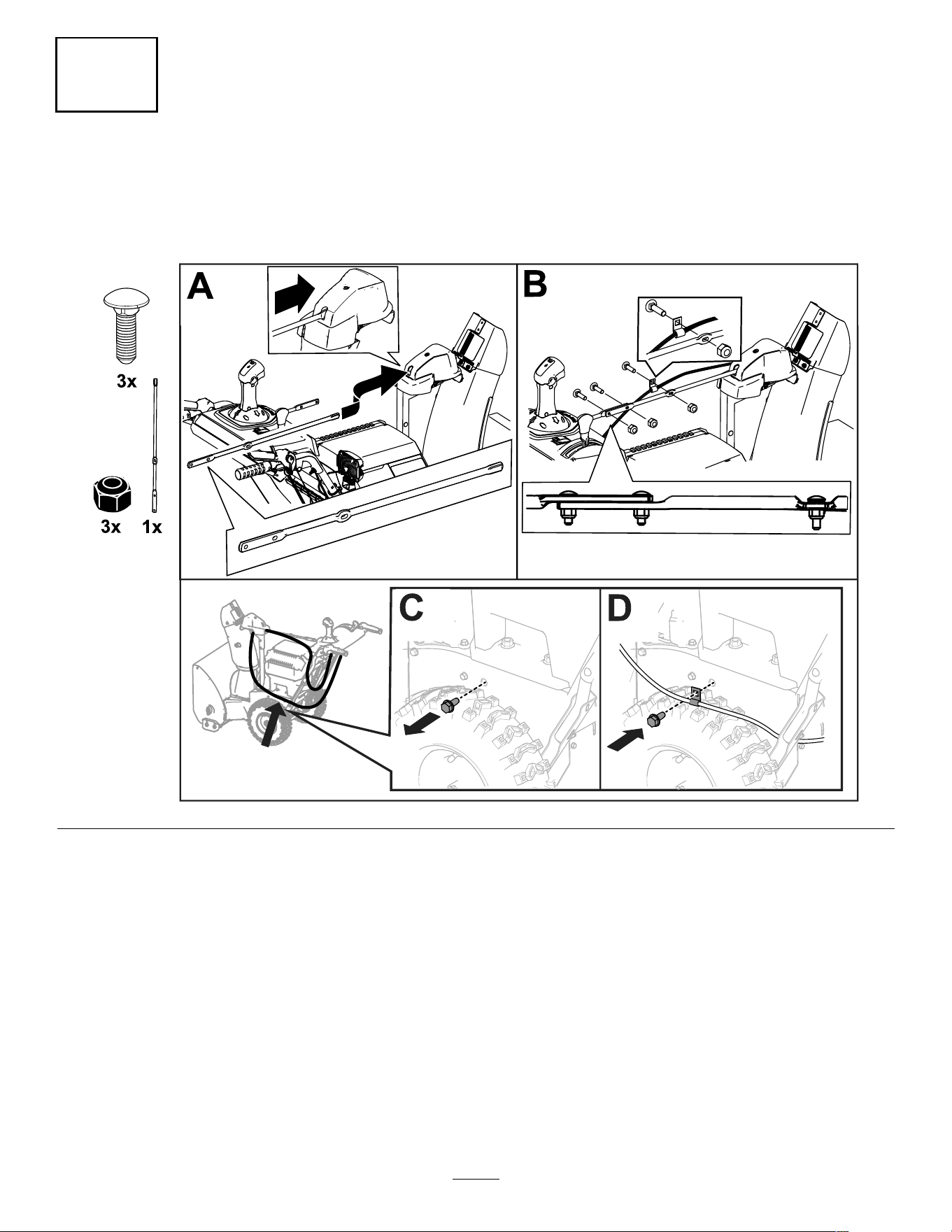
4
Installing the T raction-Control Linkage
No Parts Required
Procedure
g461560
1 1
5
Installing the Chute-Control Rod
No Parts Required
Procedure
g461558
12
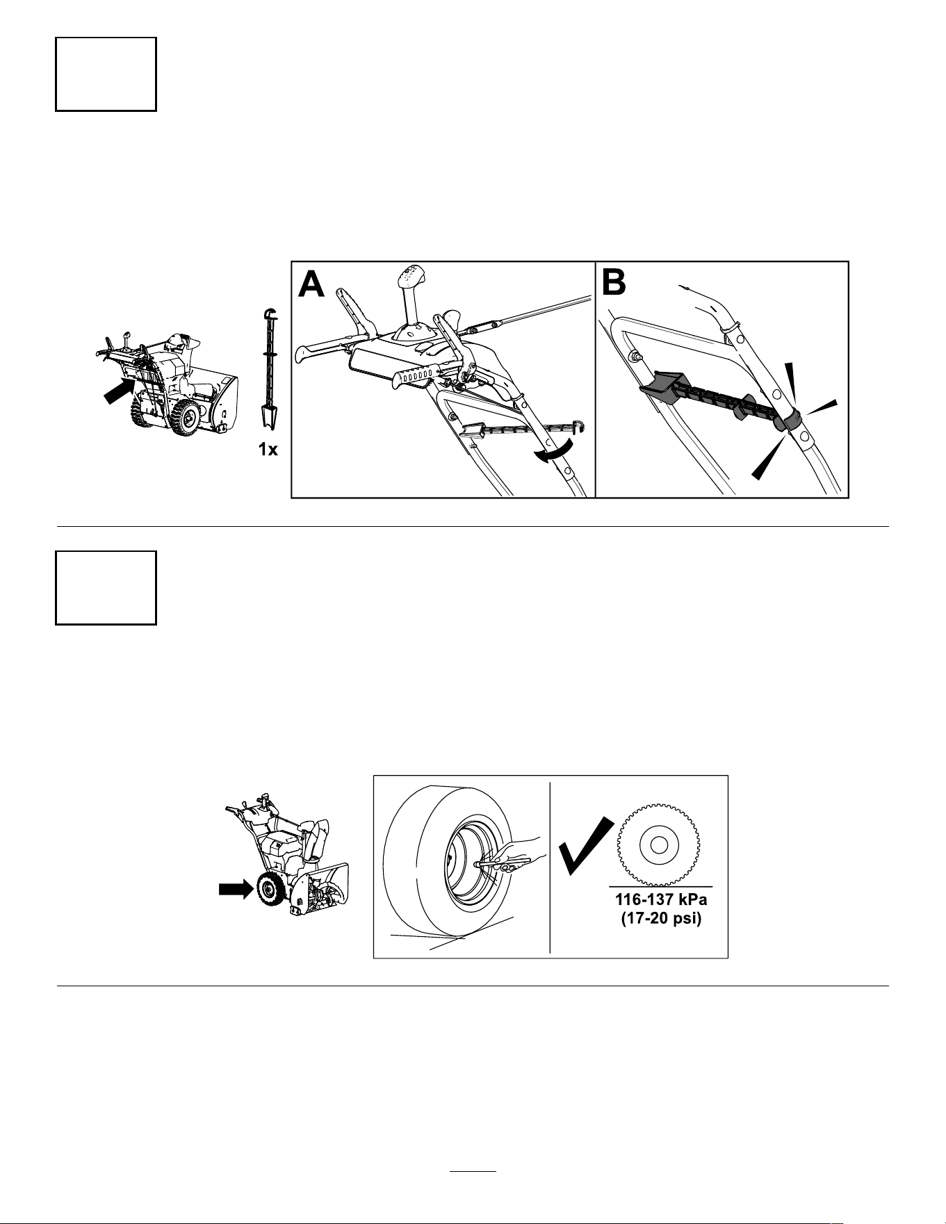
6
Installing the Snow-Cleanout T ool
No Parts Required
Procedure
g344095
7
Checking the T ire Pressure
No Parts Required
Procedure
g344084
13
8
Checking the Skids and
Scraper
No Parts Required
Procedure
Refer to 8 Checking the Skids and Scraper ( page 14 ) .
9
Adjusting the
Auger/Impeller Cable
No Parts Required
Procedure
Check and adjust the auger/impeller cable before rst
use; refer to 9 Adjusting the Auger/Impeller Cable
( page 14 ) .
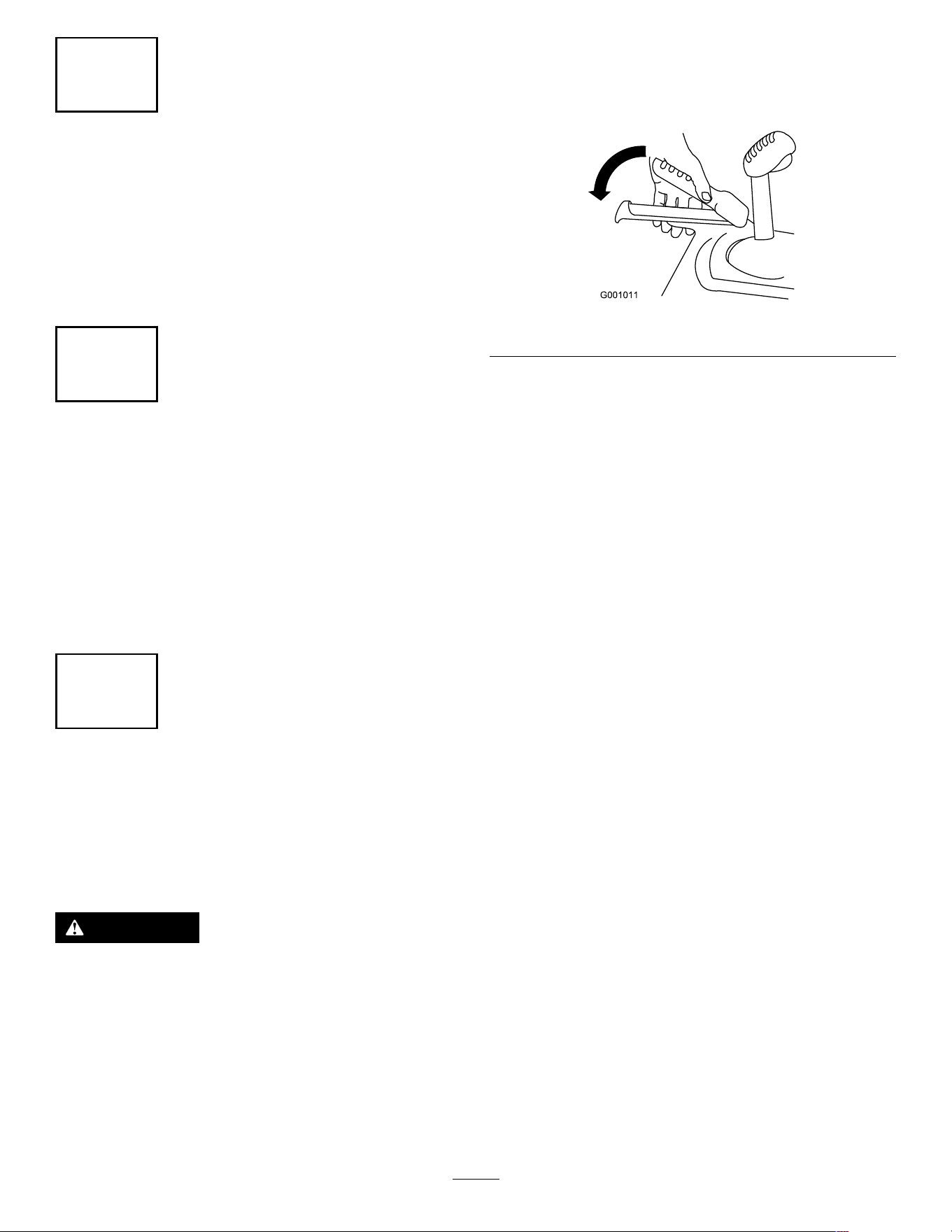
10
Checking the Operation of
the T raction Drive
No Parts Required
Procedure
CAUTION
If the traction drive is not properly adjusted,
the machine may move in the direction
opposite of what you intended, causing injury
and/or property damage.
Carefully check the traction drive and adjust it
properly , if necessary .
1. Start the machine; refer to Starting the Machine
( page 17 ) .
2. Move the speed selector to Position R1; refer to
Operating the Speed Selector ( page 19 ) .
3. Squeeze the left (traction) lever to the handgrip
( Figure 10 ).
g00101 1
Figure 10
The machine should move rearward. If the
machine does not move or moves forward,
complete the following:
A. Release the traction lever and shut of f the
machine; refer to Shutting Of f the Machine
( page 23 ) .
B. Disconnect the trunnion from the
speed-selector lever .
C. T urn the trunnion downward (clockwise) on
the speed-control rod.
D. Connect the trunnion to the speed-selector
lever .
4. Release the traction lever .
5. Move the speed selector to Position 1; refer to
Operating the Speed Selector ( page 19 ) .
6. Squeeze the left (traction) lever to the handgrip
( Figure 10 ).
The machine should move forward. If the
machine does not move or moves rearward,
complete the following:
A. Release the traction lever and shut of f the
machine.
B. Disconnect the trunnion from the
speed-selector lever .
C. T urn the trunnion upward (counterclockwise)
on the speed-control rod.
D. Connect the trunnion to the speed-selector
lever .
7. If you made any adjustments, repeat this
procedure until no adjustments are required.
Important: If the machine moves when the
traction lever is in the released position, check the
traction cable; refer to Checking and Adjusting
the T raction Cable ( page 25 ) or take the machine
to an Authorized Service Dealer for service.
14
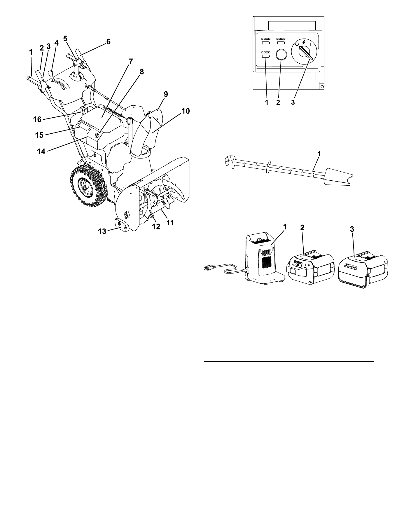
Product Overview
g360898
Figure 1 1
1. Handgrip (2) 9. Chute deector
2. Auger/impeller lever
10. Discharge chute
3. Lock switch
1 1. Scraper
4. Speed-selector lever
12. Auger
5. Quick Stick
®
discharge-chute control
13. Skid (2)
6. T raction lever
14. Control panel
7. Main battery-compartment
lid
15. Secondary
battery-compartment
lid
8. Electric-start key
16. Snow-cleanout tool
g347780
Figure 12
1. Battery charge lights
3. Key switch in O FF position
2. ECO button
g344092
Figure 13
1. Snow-cleanout tool (attached to the handle)
g446505
Figure 14
1. Battery charger Model
88602 (2 included with
Model 39924) (1 included
with Model 39925)
3. Battery pack Model 68810
(1 included with Model
39925)
2. Battery pack Model 88660
(2 included with Model
39924)
15
Specications
Model W eight Length W idth Height
78 kg
39924
(172 lb)
142 cm 62.5 cm 1 1 1.8 cm
77 kg
(56
inches)
(24.6
inches)
(44.0
inches)
39925
(170 lb)
Battery Pack
Model 88660 68810
6.0 Ah 10.0 Ah
Battery pack
capacity
324 Wh 540 Wh
Battery manufacturer rating = 60V maximum and 54V nominal.
Actual voltage varies with load.
Battery Charger
Model 88602
T ype
60V MAX Lithium-Ion Battery Charger
Input
120V AC ~2A, 60Hz
Output 60V DC 2A MAX
Appropriate T emperature Ranges
Charge/store the battery pack
at
5°C (41°F) to 40°C (104°F)*
Use the battery pack at
-30°C (-22°F) to 49°C (120°F)*
Use the machine at
-30°C (-22°F) to 49°C (120°F)*
*Charging time will increase if you do not charge the
battery within this range.
Store the machine, battery pack, and battery charger
in an enclosed clean, dry area.
Attachments/Accessories
A selection of T oro approved attachments and
accessories is available for use with the machine
to enhance and expand its capabilities. Contact
your Authorized Service Dealer or authorized T oro
distributor or go to www .T oro.com for a list of all
approved attachments and accessories.
T o ensure optimum performance and continued safety
certication of the machine, use only genuine T oro
replacement parts and accessories. Replacement
parts and accessories made by other manufacturers
could be dangerous.
Operation
Note: Determine the left and right sides of the
machine from the normal operating position.
Before Operation
Installing the Battery Pack
1. Ensure that the vents on the battery packs are
clear of any dust and debris.
2. Lift up the battery-compartment lid.
3. Line up the cavity in the battery pack with the
tongue on the machine and slide the battery
pack into the compartment until it lock into place
( Figure 9 ).
4. Close the battery-compartment lid.
5. Repeat for the other 2 battery cavities (if
needed).
Note: The combined amp hours of all the
installed batteries must add up to 6.0 or greater ,
otherwise the machine can not start.
Note: If the battery-compartment lid does not
close completely , the battery is not fully installed.
g348180
Figure 15
16
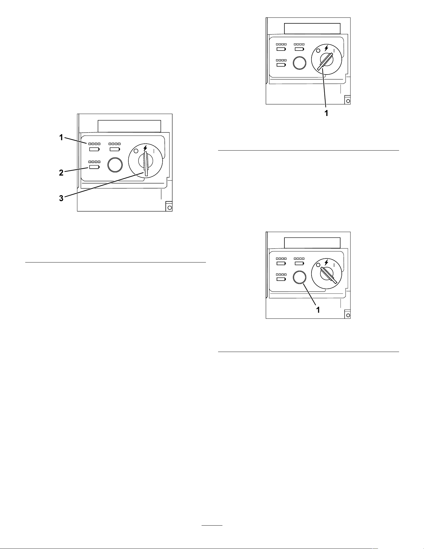
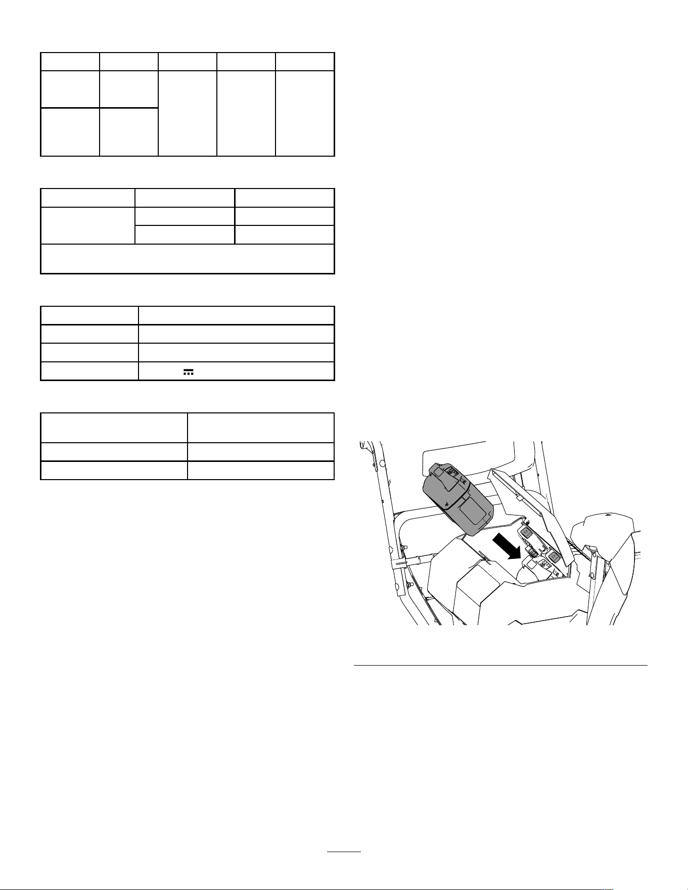
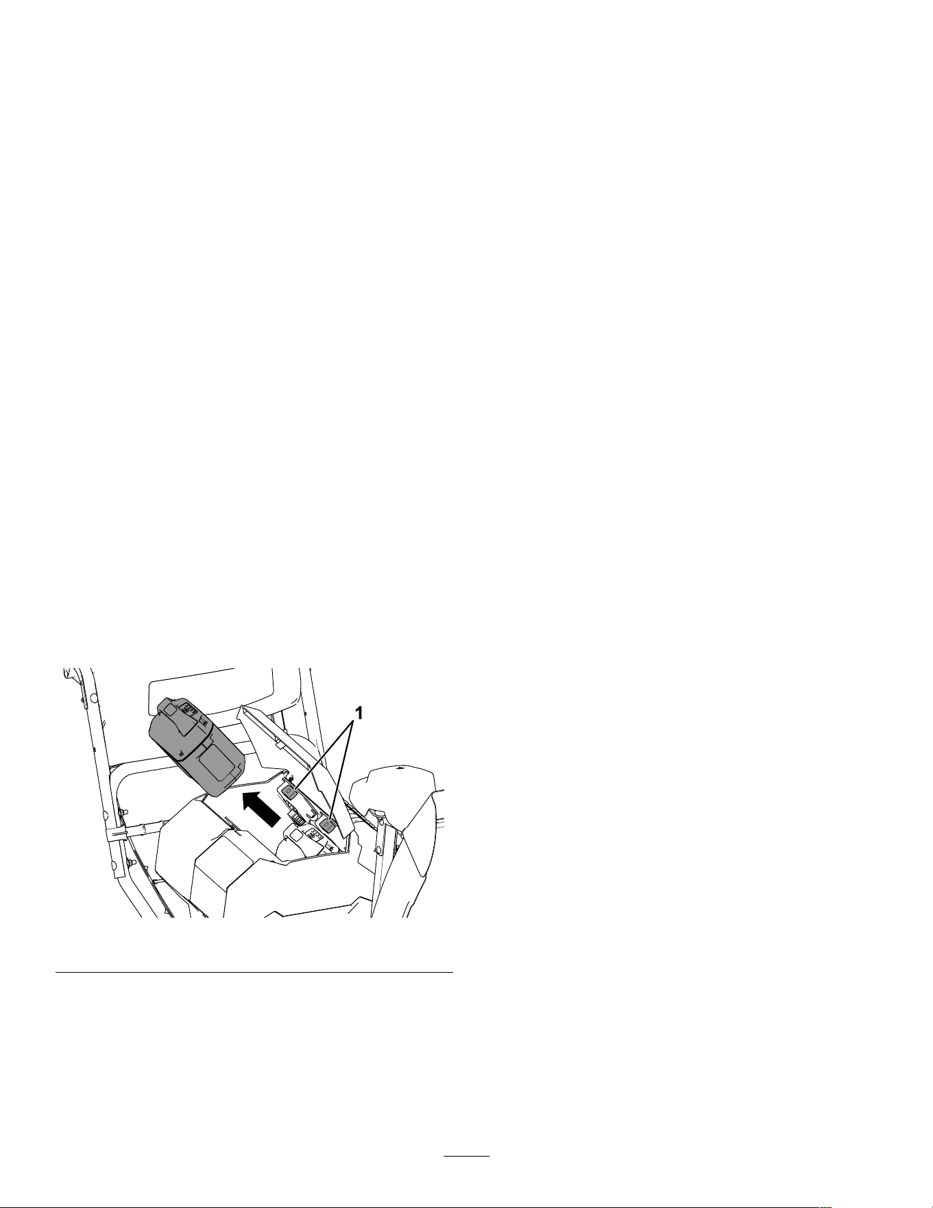
Checking the State of
Charge
Y ou can view the exact state of charge of each
installed battery; turn the key to the A CCESSORY
position ( Figure 16 ). The position of each set of lights
corresponds to the related battery cavity . If the battery
state of charge is too low and needs to be charged, or
if there is no battery in the corresponding cavity , the
battery presence light does not turn on.
g348182
Figure 16
1. State-of-charge lights
3. Key switch in the
A CCESSORY position
2. Battery presence lights
During Operation
Starting the Machine
Note: Use the battery pack only in temperatures
that are within the appropriate range; refer to
Specications ( page 16 ) .
1. Ensure that the battery pack(s) are installed in
the machine; refer to Installing the Battery Pack
( page 16 ) .
2. Insert the electric-start key into the control panel
3. T urn the key to the R UN position to turn on the
machine ( Figure 17 ).
g347864
Figure 17
1. Key switch in O N position
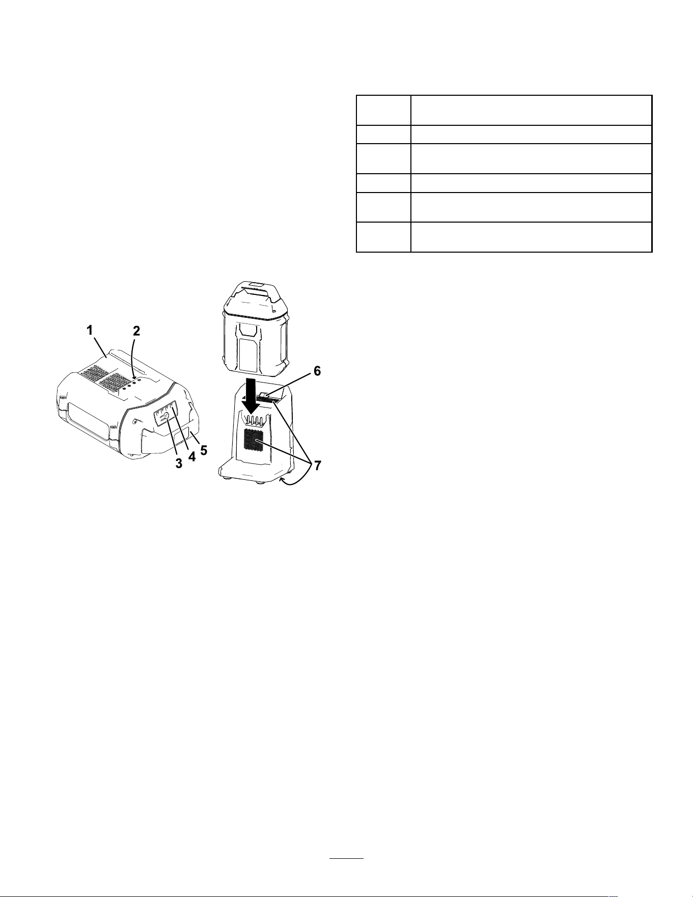
Activating ECO Mode
Using ECO mode may extend battery life by reducing
rotor speed; use ECO mode whenever you are
moving light snow , or moving snow a short distance.
Activate ECO mode using the ECO button as shown
in Figure 18 .
g347866
Figure 18
1. ECO mode button
17
Charging the Battery Pack
Important: The battery pack is not fully charged
when you purchase it. Before using the tool for
the rst time, place the battery pack in the charger
and charge it until the LED display indicates the
battery pack is fully charged. Read all safety
precautions.
Important: Charge the battery pack only in
temperatures that are within the appropriate
range; refer to Specications ( page 16 ) .
Note: At any time, press the battery-charge-indicator
button on the battery pack to display the current
charge (LED indicators).
1. Ensure that the vents on the battery charger are
clear of any dust and debris.
g473274
Figure 19
1. Battery pack cavity 5. Handle
2. Battery pack terminals
6. Charger LED indicator
light
3. Battery-charge-indicator
button
7. Charger venting areas
4. LED indicators (current
charge)
2. Line up the cavity in the battery pack ( Figure 19 )
with the tongue on the charger .
3. Slide the battery pack into the charger until it is
fully seated ( Figure 19 ).
4. T o remove the battery pack, slide the battery
backward out of the charger .
5. Refer to the following table to interpret the LED
indicator light on the battery charger .
Indicator
light
Indicates
Of f
No battery pack inserted
Green
blinking
Battery pack is charging
Green
Battery pack is charged
Red
Battery pack and/or battery charger is over or under
the appropriate temperature range
Red
blinking
Battery pack charging fault*
*Refer to T roubleshooting ( page 30 ) for more
information.
Important: The battery can be left on the charger
for short periods between uses.
If the battery will not be used for longer periods,
remove the battery from the charger; refer to
Storage ( page 29 ) .
18
Operating the T raction
Drive
CAUTION
If the traction drive is not properly adjusted,
the machine may move in the direction
opposite of what you intended, causing injury
and/or property damage.
Carefully check the traction drive and adjust
it properly , if necessary; refer to Checking
and Adjusting the T raction Cable ( page 25 ) for
more information.
Important: If the machine moves when the
traction lever is in the released position, check the
traction cable; refer to Checking and Adjusting
the T raction Cable ( page 25 ) or take the machine
to an Authorized Service Dealer for service.
1. T o engage the traction drive, squeeze the left
(traction) lever to the handgrip ( Figure 20 ).
g00101 1
Figure 20
2. T o stop the traction drive, release the traction
lever .
Operating the Speed
Selector
The speed selector has 6 forward and 2 reverse
gears. T o change speeds, release the traction lever
and shift the speed-selector lever to the desired
position ( Figure 21 ). The lever locks in a notch at
each speed selection.
g322971
Figure 21
19
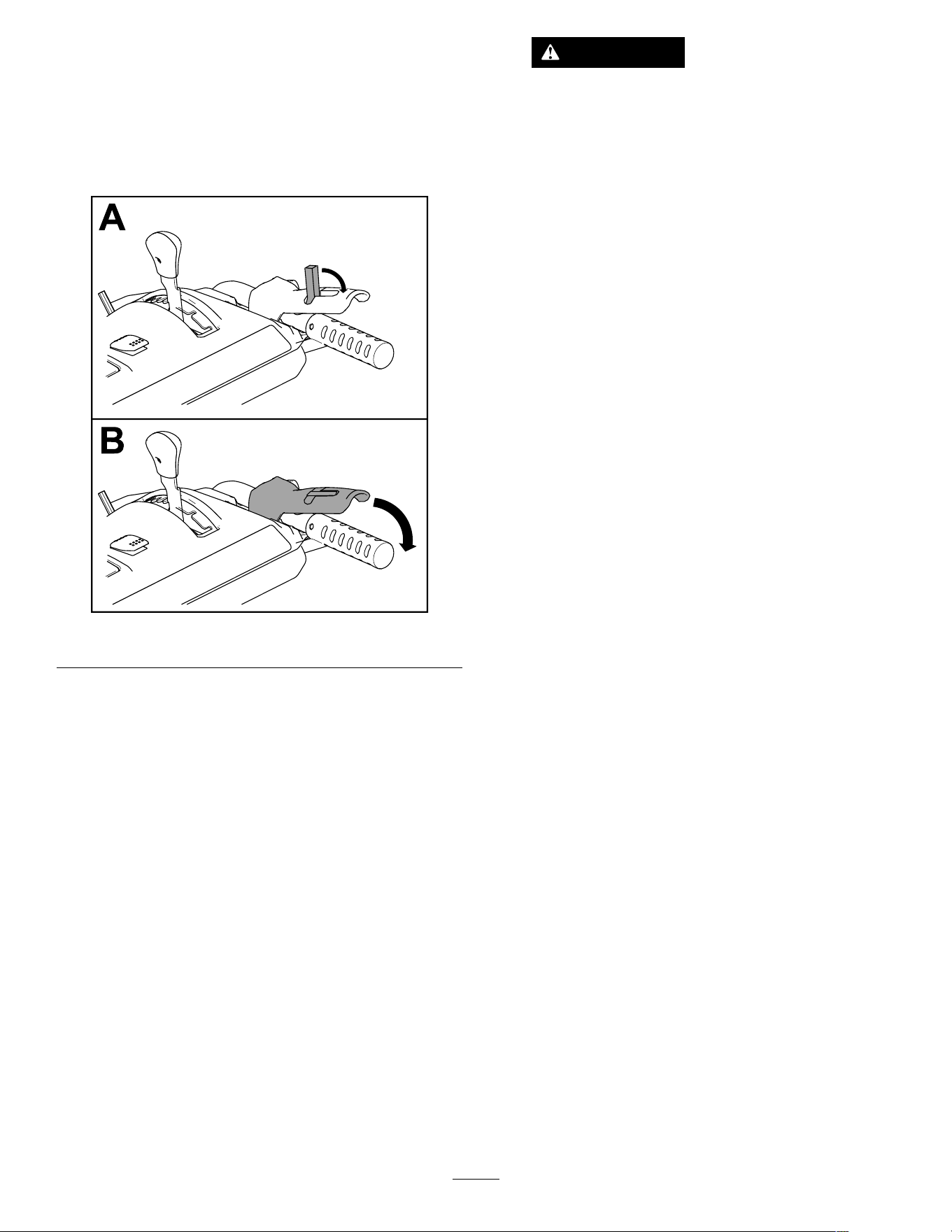
Operating the
Auger/Impeller Drive
1. T o engage the auger/impeller drive, move back
the lock switch on the lever , then squeeze the
right (auger/impeller) lever to the handgrip
( Figure 22 ).
g360687
Figure 22
2. T o stop the auger and impeller , release the right
lever .
Important: When you engage both the
auger/impeller lever and the traction lever ,
the traction lever locks the auger/impeller
lever down, freeing your right hand. T o
release both levers, simply release the left
(traction) lever .
3. If the auger and impeller continue to rotate when
you release the auger/impeller lever , do not
operate the machine. Check the auger/impeller
cable; refer to Checking and Adjusting the
Auger/Impeller Cable ( page 26 ) and adjust it if
necessary . Otherwise, take the machine to an
Authorized Service Dealer for service.
W ARNING
If the auger and impeller continue
to rotate when you release the
auger/impeller lever , you could seriously
injure yourself or others.
Do not operate the machine. T ake it to an
Authorized Service Dealer for service.
20
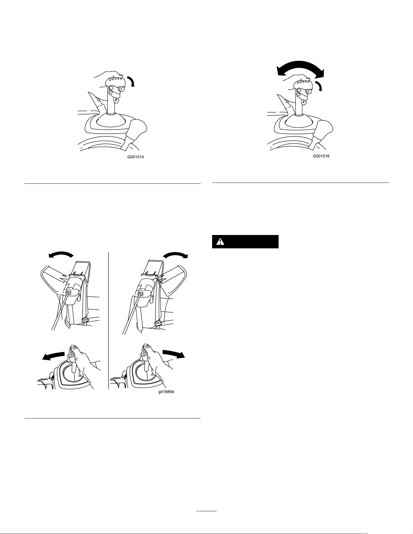
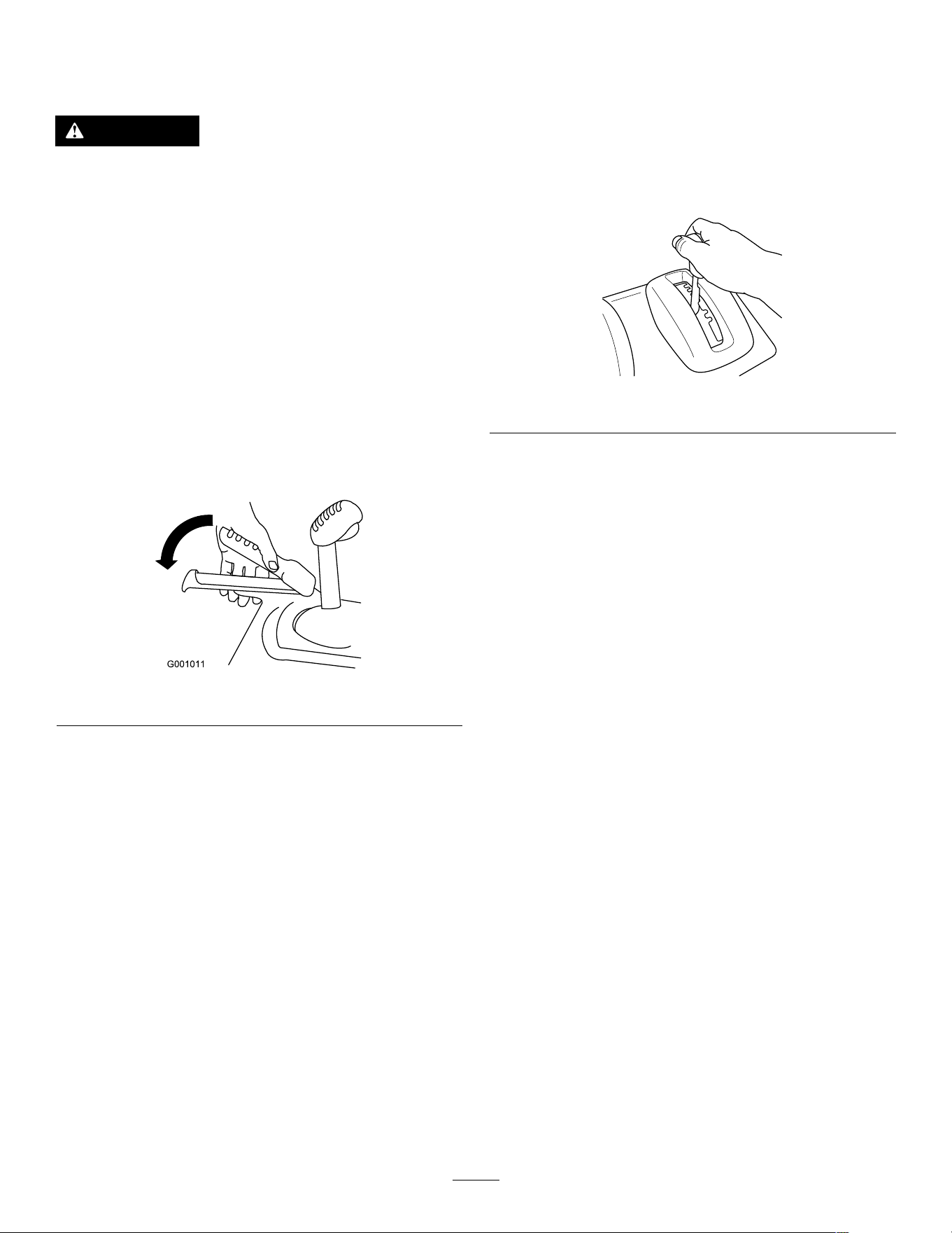
Operating the Quick Stick®
Hold the blue trigger cap down to use the Quick Stick
to move the discharge chute and the chute deector .
Release the trigger cap to lock the discharge chute
and chute deector into position ( Figure 23 ).
g001014
Figure 23
Moving the Discharge Chute
Hold the blue trigger cap down and move the Quick
Stick to the left to move the discharge chute to the
left; move the Quick Stick to the right to move the
discharge chute to the right ( Figure 24 ).
g018894
Figure 24
• If the chute does not turn as far to the left as it
does to the right, ensure that the cable is routed to
the inside of the handles. Refer to 3 Installing the
Upper Handle ( page 10 ) .
• If the chute does not move, or does not lock into
place when you release the trigger cap, you must
adjust the discharge-chute latch cable.
Moving the Chute Deector
Hold the blue trigger cap down and move the Quick
Stick forward to lower the chute deector; move it
rearward to raise the chute deector ( Figure 25 ).
g001016
Figure 25
Clearing a Clogged
Discharge Chute
W ARNING
If the auger/impeller is running but there is no
snow coming out of the discharge chute, the
discharge chute may be clogged.
Never use your hands to clear a clogged
discharge chute. This could result in personal
injury .
• T o unclog the discharge chute, stay in the
operating position and release the left (traction)
lever . While running the auger/impeller , push down
on the handles to raise the front of the machine a
few centimeters (inches) of f the pavement. Then
lift the handles quickly to bump the front of the
machine on the pavement. Repeat if necessary
until a stream of snow comes out the discharge
chute.
• If you cannot unclog the discharge chute by
bumping the front of the machine, shut off the
machine, wait for all moving parts to stop, and
use the snow-cleanout tool ( Figure 13 ).
Important: Unclogging the discharge chute
by bumping the front of the machine on the
pavement may cause the skids to move. Adjust
the skids and tighten the skid bolts securely;
refer to Checking and Adjusting the Skids and
Scraper ( page 24 ) .
21

Operating T ips
DANGER
When the machine is in operation, the impeller
and auger rotate and can injure or amputate
hands or feet.
• Before adjusting, cleaning, inspecting,
troubleshooting, or repairing the machine,
shut off the machine and wait for all
moving parts to stop. Remove the key and
the battery from the machine to prevent
someone from accidentally starting the
machine.
• Remove any obstructions from the
discharge chute; refer to Clearing a
Clogged Discharge Chute ( page 21 ) . Use
the snow-cleanout tool ( Figure 13 ), not
your hands, to remove an obstruction from
the discharge chute.
• Stay behind the handles and away from
the discharge opening while operating the
machine.
• Keep your face, hands, feet, and any other
part of your body or clothing away from
concealed, moving, or rotating parts.
W ARNING
The impeller can throw stones, toys, and other
foreign objects and cause serious personal
injury to you or bystanders.
• Keep the area to be cleared free of all
objects that the auger could pick up and
throw .
• Keep all children and pets away from the
area of operation.
For best results, consider the following:
• If the machine slows down under a load or the
wheels slip, shift the machine into a lower gear;
refer to Operating the Speed Selector ( page 19 ) .
• If the front of the machine rides up, shift the
machine into a lower gear . If the front continues to
ride up, lift up on the handles.
• Remove the snow as soon as possible after it falls.
• Push the machine forward, but allow it to work at
its own pace.
• Overlap each swath to ensure complete snow
removal.
• Discharge the snow downwind whenever possible.
22
After Operation
Shutting Off the Machine
1. Release the traction and auger/impeller levers.
2. T urn the key to the O FF position and remove it
from the control panel ( Figure 12 ).
3. Remove the battery pack(s); refer to Removing
the Battery Pack from the Machine ( page 23 ) .
Note: Whenever you are not using the machine,
remove the battery pack(s) and the key from
the machine.
Note: If the machine is turned on and left idling
or operating without the auger engaged for an
extended period, the motor shutof f timeout will
engage, shutting of f the machine. When the
machine shuts of f this way it beeps to indicate
that the timeout was engaged.
T o restart the machine refer to Starting the
Machine ( page 17 ) .
Removing the Battery Pack
from the Machine
1. Lift up the battery-compartment lid.
2. Press the battery pack-latch to release the
battery pack and remove the battery pack
( Figure 26 ).
g347853
Figure 26
3. Close the battery-compartment lid.
Preventing Freeze-up after
Use
• In snowy and cold conditions, some controls and
moving parts may freeze. Do not use excessive
force when trying to operate frozen controls.
• After using the machine, engage the auger to
clear any remaining snow from inside the housing.
Rotate the Quick Stick to prevent it from freezing.
Shut of f the machine, wait for all moving parts to
stop, remove the key and the battery , and remove
all ice and snow from the machine.
• Clean of f any snow and ice from the base of the
chute.
• Rotate the discharge chute to the left and right to
free it from any ice buildup.
23
Maintenance
Recommended Maintenance Schedule(s)
Maintenance Service
Interval
Maintenance Procedure
After the rst 2 hours
• Inspect the traction cable and adjust it if necessary .
• Inspect the auger/impeller cable and adjust it if necessary .
Y early
• Check the skids and the scraper and adjust them if necessary .
• Inspect the traction cable and adjust or replace it if necessary .
• Inspect the auger/impeller cable and adjust or replace it if necessary .
• Check the auger-gearbox oil and add oil if necessary .
• Lubricate the hex shaft.
Y early or before storage
• Check the air pressure in the tires and inate them to 1 16 to 137 kPa (17 to 20 psi).
• Have an Authorized Service Dealer inspect and replace the traction-drive belt and/or
the auger/impeller drive belt, if necessary .
Preparing for Maintenance
1. Move the machine to a level surface.
2. Stop the machine, remove the electric-start
key , wait for all movement to stop, and remove
the battery pack(s) from the machine before
adjusting, servicing, cleaning, or storing the
machine.
Checking and Adjusting the
Skids and Scraper
Service Interval : Y early —Check the skids and
the scraper and adjust them if
necessary .
Check the skids and the scraper to ensure that the
auger does not contact the paved or gravel surface.
Adjust the skids and the scraper as needed to
compensate for wear .
1. Check the tire pressure; refer to 7 Checking the
T ire Pressure ( page 13 ) .
2. Loosen the nuts that secure both skids to the
auger sides until the skids slide up and down
easily .
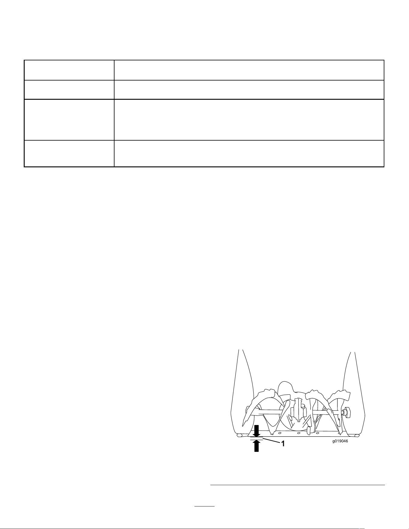
Important: The auger blades must be
supported above the ground by the skids.
g019046
Figure 27
1. 3 mm (1/8 inch)
24
3. Ensure that the scraper is 3 mm (1/8 inch) above
and parallel to a level surface.
Note: If the pavement is cracked, rough, or
uneven, adjust the skids to raise the scraper . For
gravel surfaces, adjust the skids further down to
prevent the machine from picking up rocks.
4. Move the skids down until they are even with
the ground.
5. Firmly tighten the nuts that secure both skids
to the auger sides.
Note: T o easily adjust the skids if they loosen,
support the scraper 3 mm (1/8 inch) of f the
pavement, then adjust the skids down to the
pavement.
Note: If the skids become excessively worn,
you can turn them over and set the unused side
toward the pavement.
Checking and Adjusting the
T raction Cable
Service Interval : After the rst 2 hours —Inspect
the traction cable and adjust it if
necessary .
Y early —Inspect the traction cable and adjust or
replace it if necessary .
If the machine does not drive in the forward or reverse
speeds or it drives when you release the traction lever ,
adjust the traction cable.
If the left (traction) cable is not properly adjusted, do
the following steps:
1. Loosen the jam nut.
2. Engage the traction lever and hold it in place
( Figure 28 ).
g00101 1
Figure 28
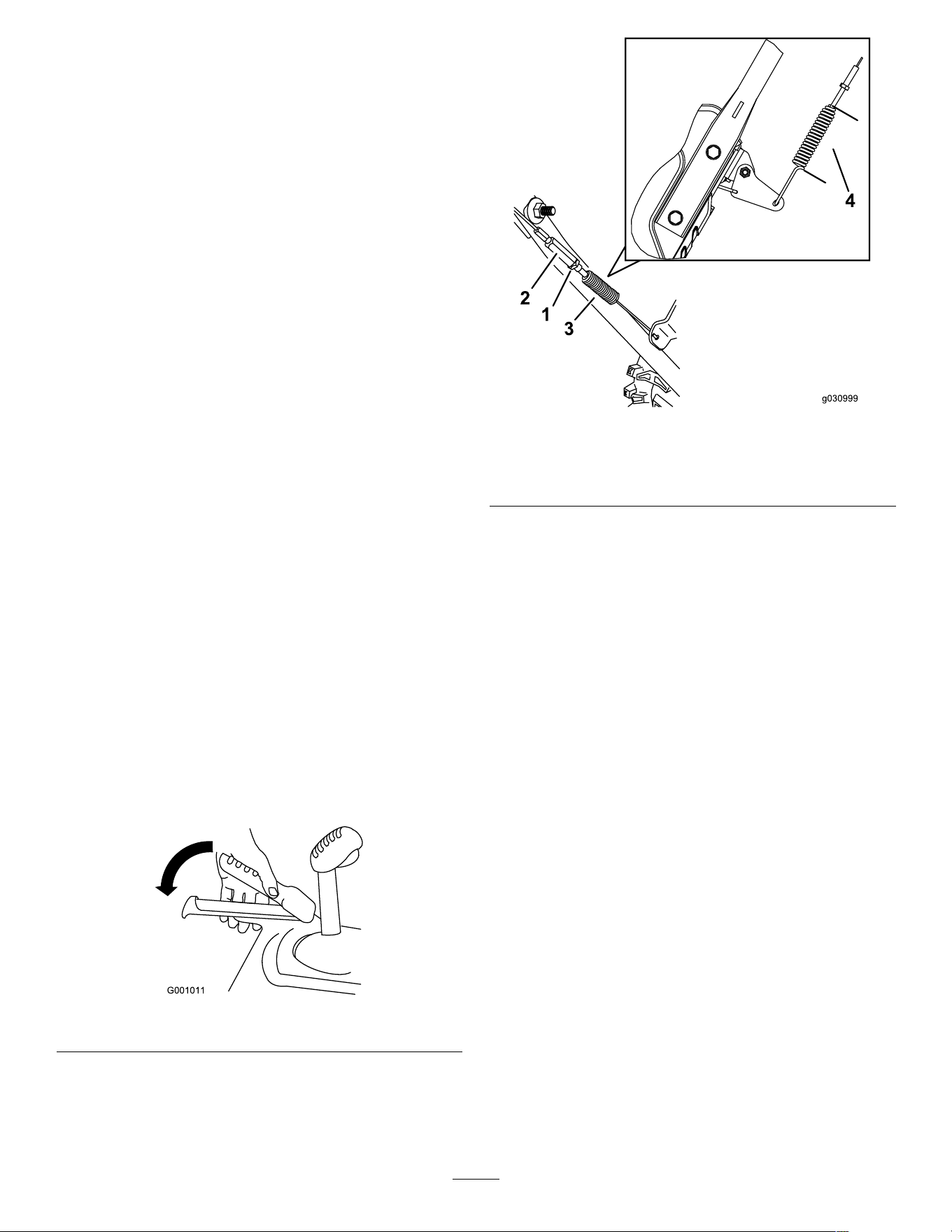
3. Loosen or tighten the turnbuckle to adjust the
spring length to 5.5 cm (2–3/16 inches) as
shown in Figure 29 .
g030998
Figure 29
1. Jam nut
3. Spring
2. T urnbuckle
4. 5.5 cm (2–3/16 inches)
4. T ighten the jam nut ( Figure 29 ), ensuring that
there is slight tension on the cable.
5. If the traction cable is properly adjusted but a
problem remains, contact an Authorized Service
Dealer .
25
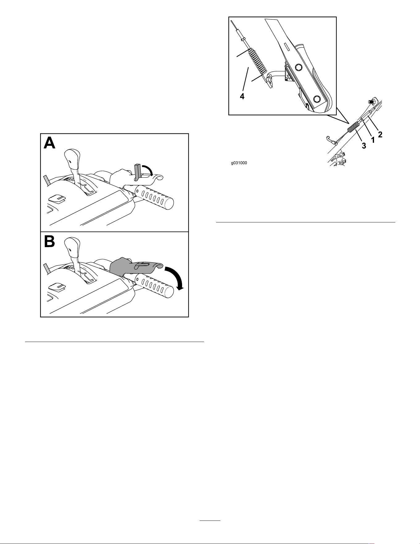
Checking and Adjusting the
Auger/Impeller Cable
Service Interval : After the rst 2 hours —Inspect the
auger/impeller cable and adjust it if
necessary .
Y early —Inspect the auger/impeller cable and
adjust or replace it if necessary .
1. Loosen the jam nut ( Figure 31 ).
2. Engage the auger/impeller lever and hold it in
place ( Figure 30 ).
g360687
Figure 30
3. Loosen or tighten the turnbuckle to adjust the
spring length to 6.6 cm (2-3/5 inches) as shown
in Figure 31 .
g031000
Figure 31
1. T urnbuckle
3. Spring
2. Jam nut
4. 6.6 cm (2-3/5 inches) while
the auger/impeller lever is
held down.
4. T ighten the jam nut ( Figure 31 ), ensuring that
there is slight tension on the cable.
5. T urn on the machine and attempt to engage the
auger/impeller drive without moving the lock
switch back; if the auger rotates, loosen the
turnbuckle so that the auger does not engage.
6. If the auger/impeller cable is properly adjusted
but a problem remains, contact an Authorized
Service Dealer .
26
Checking the
Auger-Gearbox-Oil Level
Service Interval : Y early —Check the auger-gearbox
oil and add oil if necessary .
1. Move the machine to a level surface.
2. Clean the area around the pipe plug ( Figure 32 ).
g016782
Figure 32
1. Pipe plug
3. Remove the pipe plug from the gearbox.
4. Check the oil level in the gearbox. The oil should
be 9.5 mm (3/8 inch) below the ller opening.
5. If the oil level is low , add GL-5 or GL-6, SAE
80-90 EP gear oil lubricant to the gearbox until
the oil level is 9.5 mm (3/8 inch) below the ller
opening.
Note: Do not use synthetic oil.
6. Install the pipe plug in the gearbox.
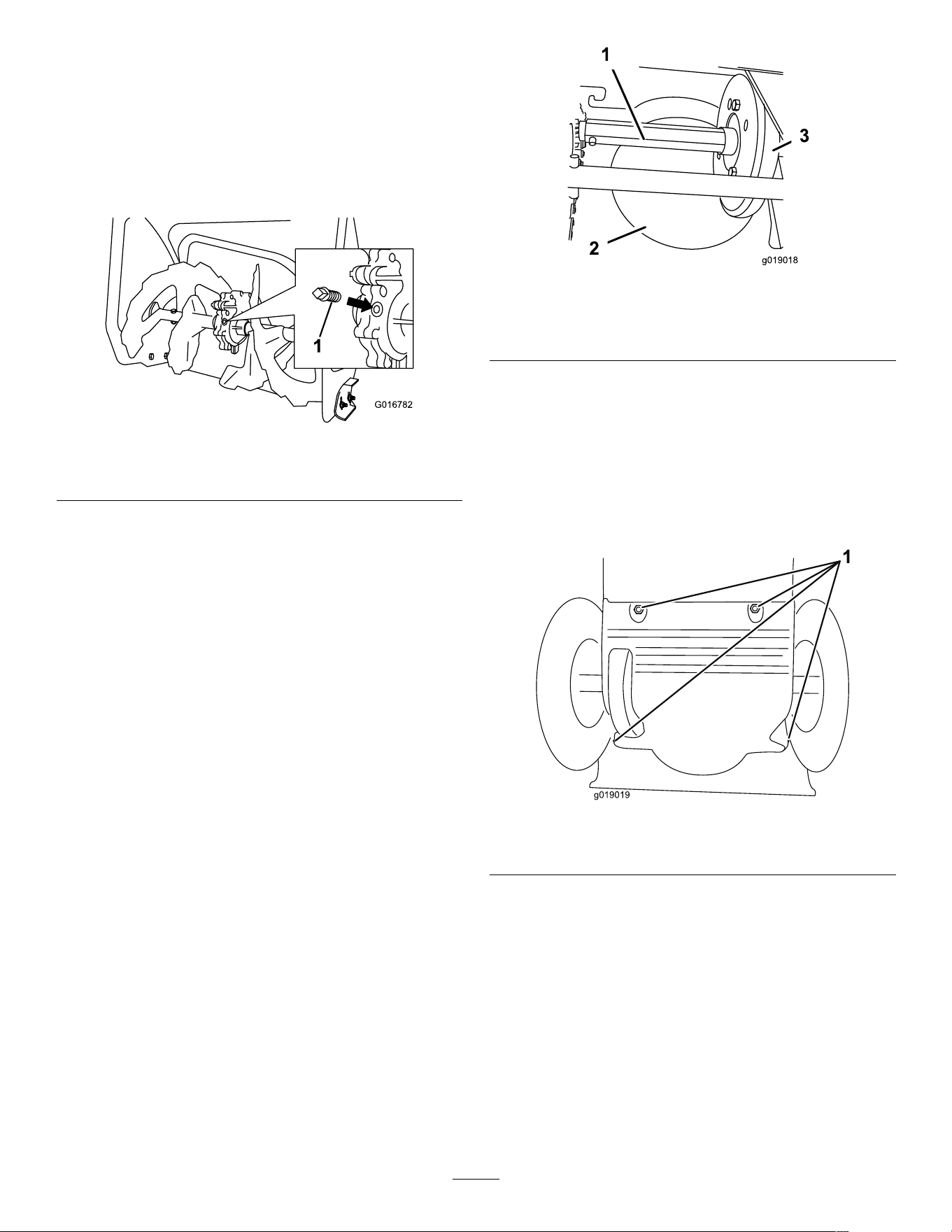
Lubricating the Hex Shaft
Service Interval : Y early —Lubricate the hex shaft.
Lightly lubricate the hex shaft yearly with automotive
engine oil ( Figure 33 ).
g019018
Figure 33
1. Hex shaft
3. Rubber wheel
2. Steel friction pulley
Important: Do not get oil on the rubber wheel or
the steel friction pulley because the traction drive
will slip ( Figure 33 ).
1. Drain the fuel from the fuel tank.
2. T ip the machine forward onto its auger housing
and block it so that it cannot fall.
3. Remove the back cover ( Figure 34 ).
g019019
Figure 34
1. Screws
4. Move the speed-selector lever to Position R2.
5. Dip your nger in automotive engine oil and
lightly lubricate the hex shaft.
6. Move the speed-selector lever to Position 6.
7. Lubricate the other end of the hex shaft.
8. Move the speed-selector lever forward and
rearward a few times.
9. Install the back cover and return the machine to
the operating position.
27

Replacing the Drive Belts
If the auger/impeller drive belt or the traction-drive belt
becomes worn, oil-soaked, or otherwise damaged,
have an Authorized Service Dealer replace the belt.
28

Storage
Storing the Machine
Important: Store the machine, battery pack, and
charger only in temperatures that are within the
appropriate range; refer to Specications ( page
16 ) .
Important: If you are storing the battery pack
for the off-season, charge it until 2 or 3 LED
indicators turn green on the battery . Do not store
a fully charged or fully depleted battery . When
you are ready to use the machine again, charge
the battery pack until the left indicator light turns
green on the charger or all 4 LED indicators turn
green on the battery .
• Disconnect the product from the power supply
(i.e., remove the plug from the power supply or
the battery pack), remove the key , and check for
damage after use.
• Clean all foreign material from the product.
• Do not store the tool with the battery pack installed.
• When not in use, store the machine, battery
pack, key , and battery charger out of the reach of
children.
• Keep the machine, battery pack, key , and battery
charger away from corrosive agents, such as
garden chemicals and de-icing salts.
• T o reduce the risk of serious personal injury , do
not store the battery pack outside or in vehicles.
• T ouch up chipped surfaces with paint available
from an Authorized Service Dealer . Sand af fected
areas before painting, and use a rust preventative
to prevent the metal parts from rusting.
• T ighten all loose screws, bolts, and locknuts.
Repair or replace any damaged parts.
• Store the machine, battery pack, key , and battery
charger in an enclosed clean, dry area.
Preparing the Battery Pack for
Recycling
Important: Upon removal, cover the terminals of
the battery pack with heavy-duty adhesive tape.
Do not attempt to destroy or disassemble the
battery pack or remove any of its components.
Lithium-ion battery packs labeled with the
Call2Recycle seal can be recycled at any
participating retailer or battery recycling
facility in the Call2Recycle program (US
and Canada only). T o locate a participating
retailer or facility closest to you, please call
1-800-822-8837 or visit www .call2recycle.org.
If you cannot locate a participating retailer or
facility nearby , or if your rechargeable battery
is not labeled with the Call2Recycle seal,
please contact your local municipality for more
information on how to responsibly recycle the
battery . If you are located outside of the US
and Canada, please contact your authorized
T oro distributor .
29

T roubleshooting
Perform only the steps described in these instructions. All further inspection, maintenance, and repair work
must be performed by an authorized service center or a similarly qualied specialist if you cannot solve the
problem yourself.
Always remove all batteries from the machine when troubleshooting, inspecting, maintaining, or cleaning
the machine.
Problem
Possible Cause Corrective Action
1. The motor shutof f timeout was reached
because the auger was not engaged
for an extended period of time.
1. No issue, restart the machine. The
machine beeps to indicate that the
motor shutof f timeout was reached.
2. The key was turned from O FF to O N
too quickly .
2. T urn the key slower , ensure that
the key stops briey in the middle
A CCESSORY position.
3. The battery pack is low on charge.
3. Charge the battery pack.
4. The battery pack is not fully seated.
4. Ensure that the battery pack is inserted
all the way into the housing and latched
in place.
5. The battery pack is over or under the
appropriate temperature range.
5. Move the battery pack to a place
where it is dry and the temperature is
between 5°C (41°F) and 40°C (104°F).
6. The battery pack has exceeded high
amperage limits.
6. Cycle the key to the OFF position.
7. There is moisture on the leads of the
battery pack.
7. Allow the battery pack to dry or wipe it
dry .
8. The battery pack is damaged. 8. Replace the battery pack.
The machine does not run or does not run
continuously .
9. There is another electrical problem
with the machine.
9. Contact an Authorized Service Dealer .
1. The battery pack charge capacity is
too low .
1. Remove the battery pack from the
machine and fully charge the battery
pack.
The machine does not reach full power .
2. The air vents are blocked.
2. Clean the air vents.
1. The motor shutof f timeout was reached
because the auger was not engaged
for an extended period of time.
1. No issue, restart the machine. The
machine beeps to indicate that the
motor shutof f timeout was reached.
2. The battery pack is low on charge.
2. Charge the battery pack.
3. The machine is overloaded. 3. W alk at a slower pace while clearing
snow or break up a large pile of snow
before clearing it.
The machine is producing a beeping
sound.
4. There is another electrical problem
with the machine.
4. Attempt the other troubleshooting
actions, if the alarm still sounds,
contact an Authorized Service Dealer .
30

Problem
Possible Cause Corrective Action
1. Y ou are trying to remove too much
snow per swath.
1. Reduce the amount of snow removed
per swath.
2. Y ou are trying to remove extremely
heavy or wet snow .
2. Do not overload the machine with
extremely heavy or wet snow .
3. The discharge chute is plugged. 3. Unclog the discharge chute.
4. The auger/impeller drive belt is loose
or is of f the pulley .
4. Install and/or adjust the auger/impeller
drive belt; refer to www .T oro.com
for servicing information or take the
machine to an Authorized Service
Dealer .
5. The auger drive belt is worn or broken.
5. Replace the auger drive belt; refer to
www .T oro.com for servicing information
or take the machine to an Authorized
Service Dealer .
The machine runs, but the machine
discharges snow poorly or not at all.
6. Y ou are using the machine in ECO
mode in heavy conditions.
6. V erify that ECO mode is not engaged
in heavy conditions.
The discharge chute either does not lock
into place or does not move.
1. The discharge-chute latch cable is not
properly adjusted.
1. Adjust the discharge-chute latch cable.
1. The skids and/or scraper are not
properly adjusted.
1. Adjust the skids and/or the scraper .
The machine does not properly clear the
snow of f the surface.
2. The pressure in the tires is not equal.
2. Check and adjust the pressure in 1 or
both tires.
The LED battery charge light on the
powerhead is red.
1. The battery temperature and/or voltage
outside of operating range.
1. V erify the battery condition and charge
level with charger .
1. The battery pack is over or under the
appropriate temperature range.
1. Move the battery pack to a place
where it is dry and the temperature is
between 5°C (41°F) and 40°C (104°F).
The battery pack loses charge quickly .
2. The machine is overloaded.
2. Push the machine with less force.
1. The battery charger is over or under
the appropriate temperature range.
1. Unplug the battery charger and move
it to a place where it is dry and the
temperature is between 5°C (41°F)
and 40°C (104°F).
The battery charger is not working.
2. The outlet that the battery charger is
plugged into does not have power .
2. Contact your licensed electrician to
repair the outlet.
The LED indicator light on the battery
charger is red.
1. The battery charger and/or battery
pack is over or under the appropriate
temperature range.
1. Unplug the battery charger and move
the battery charger and battery pack
to a place where it is dry and the
temperature is between 5°C (41°F)
and 40°C (104°F).
1. There is an error in the communication
between the battery pack and the
charger .
1. Remove the battery pack from the
battery charger , unplug the battery
charger from the outlet, and wait 10
seconds. Plug the battery charger into
the outlet again and place the battery
pack on the battery charger . If the LED
indicator light on the battery charger is
still blinking red, repeat this procedure
again. If the LED indicator light on
the battery charger is still blinking
red after 2 attempts, contact your
authorized service dealer if the battery
is in warranty , or properly dispose of
the battery pack at a battery recycling
facility .
The LED indicator light on the battery
charger is blinking red.
2. The battery pack is weak.
2. Contact your authorized service dealer
if the battery is in warranty , or properly
dispose of the battery pack at a battery
recycling facility .
31

California Proposition 65 W arning Information
What is this warning?
Y ou may see a product for sale that has a warning label like the following:
W ARNING: Cancer and Reproductive Harm—www .p65W arnings.ca.gov .
What is Prop 65?
Prop 65 applies to any company operating in California, selling products in California, or manufacturing products that may be sold in or brought into
California. It mandates that the Governor of California maintain and publish a list of chemicals known to cause cancer , birth defects, and/or other
reproductive harm. The list, which is updated annually , includes hundreds of chemicals found in many everyday items. The purpose of Prop 65 is to
inform the public about exposure to these chemicals.
Prop 65 does not ban the sale of products containing these chemicals but instead requires warnings on any product, product packaging, or literature with
the product. Moreover , a Prop 65 warning does not mean that a product is in violation of any product safety standards or requirements. In fact, the
California government has claried that a Prop 65 warning “is not the same as a regulatory decision that a product is ‘safe’ or ‘unsafe.’” Many of these
chemicals have been used in everyday products for years without documented harm. For more information, go to https://oag.ca.gov/prop65/faqs-view-all .
A Prop 65 warning means that a company has either (1) evaluated the exposure and has concluded that it exceeds the “no signicant risk level”; or (2)
has chosen to provide a warning based on its understanding about the presence of a listed chemical without attempting to evaluate the exposure.
Does this law apply everywhere?
Prop 65 warnings are required under California law only . These warnings are seen throughout California in a wide range of settings, including but not
limited to restaurants, grocery stores, hotels, schools, and hospitals, and on a wide variety of products. Additionally , some online and mail order
retailers provide Prop 65 warnings on their websites or in catalogs.
How do the California warnings compare to federal limits?
Prop 65 standards are often more stringent than federal and international standards. There are various substances that require a Prop 65 warning
at levels that are far lower than federal action limits. For example, the Prop 65 standard for warnings for lead is 0.5 μg/day , which is well below
the federal and international standards.
Why don’t all similar products carry the warning?
• Products sold in California require Prop 65 labelling while similar products sold elsewhere do not.
• A company involved in a Prop 65 lawsuit reaching a settlement may be required to use Prop 65 warnings for its products, but other companies
making similar products may have no such requirement.
• The enforcement of Prop 65 is inconsistent.
• Companies may elect not to provide warnings because they conclude that they are not required to do so under Prop 65; a lack of warnings for a
product does not mean that the product is free of listed chemicals at similar levels.
Why does T oro include this warning?
T oro has chosen to provide consumers with as much information as possible so that they can make informed decisions about the products they buy and
use. T oro provides warnings in certain cases based on its knowledge of the presence of one or more listed chemicals without evaluating the level of
exposure, as not all the listed chemicals provide exposure limit requirements. While the exposure from T oro products may be negligible or well within the
“no signicant risk” range, out of an abundance of caution, T oro has elected to provide the Prop 65 warnings. Moreover , if T oro does not provide these
warnings, it could be sued by the State of California or by private parties seeking to enforce Prop 65 and subject to substantial penalties.
Rev A
