
1
2
3
4
5
6
7
8
26
25
23
24
22
21
20
19
18
17
14
15
16
14
13
12
11
10
9
27
28
29
30
31
32
33
34
35
36
37
38
39
41
45
44
43
48
46
42
47
40
37 38
39
50
3 4 5 6 7 8 9 10 11 13 14 15 16 17 18 19 20
21 22 23 24 25 26 27 28 29 30 31 32 33 34 35 36 38
49
42 47
52 53
53
52
*
See detail
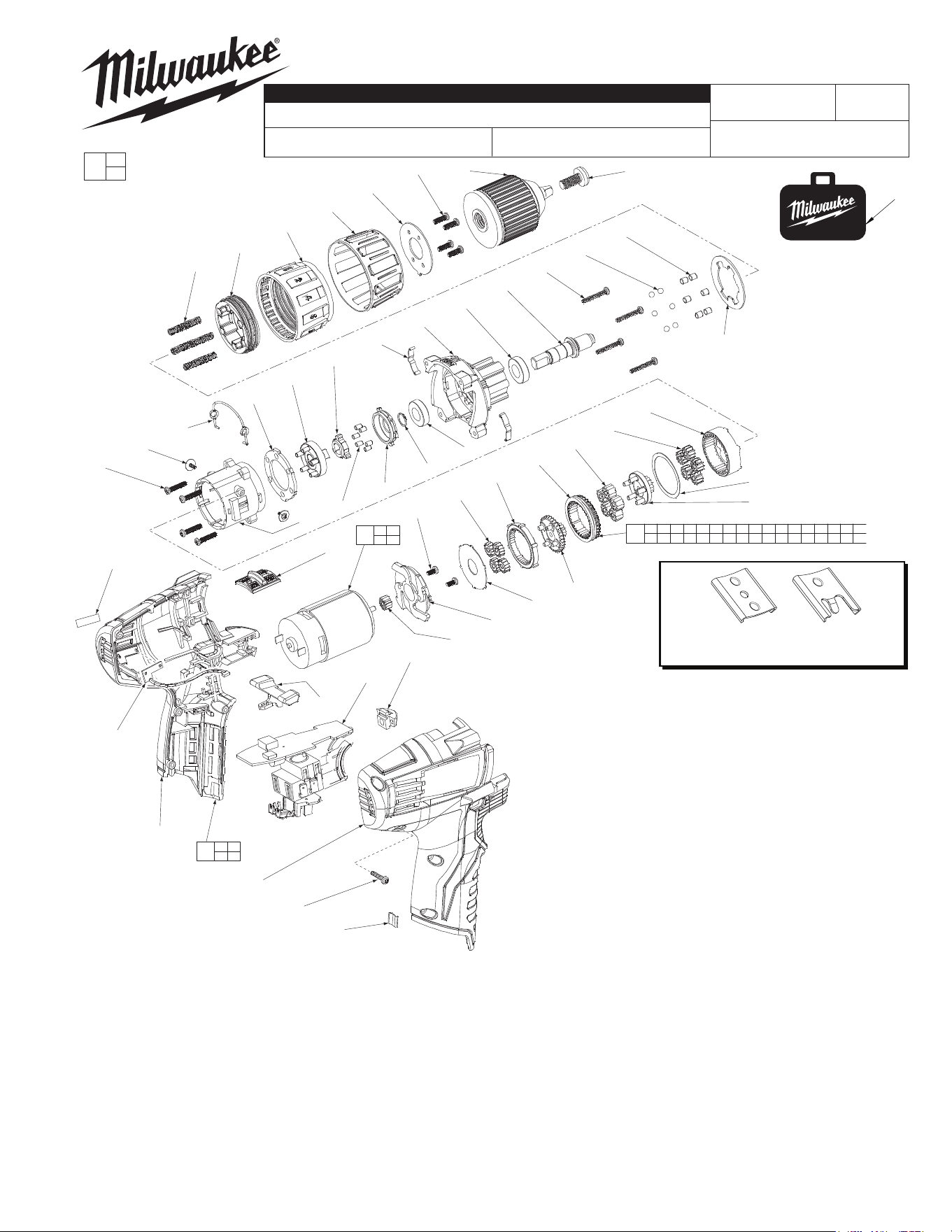
BULLETIN NO.
54-06-2410
SERVICE PARTS LIST
FIG. PART NO. DESCRIPTION OF PART NO. REQ.
1 05-88-1680 Chuck Screw (1)
2 42-66-0530 Chuck (1)
3 --------------- M3 x 10 Screw (4)
4 --------------- Spring plate Holder (1)
5 --------------- Clutch Ring Cap (1)
6 --------------- Clutch Ring Cup (1)
7 --------------- Sleeve (1)
8 --------------- Spring (6)
9 --------------- Clutch Washer (1)
10 --------------- Pin (6)
11 --------------- Ball (6)
12 06-82-7336 Gearcase Screw (4)
13 --------------- Output Shaft (1)
14 --------------- Ball Bearing (2)
15 --------------- Stamping (2)
16 --------------- Front Gearcase Housing (1)
17 --------------- Retaining Ring (1)
18 --------------- Outer Bracket (1)
19 --------------- Locking Pin (6)
20 --------------- Cam Plate (1)
CATALOG NO. 2410-20
REVISED BULLETIN
SPECIFY CATALOG NO. AND SERIAL NO. WHEN ORDERING PARTS
Cordless M12™ 3/8" Driver Drill
STARTING
SERIAL NO.
WIRING INSTRUCTION
C10A
SEE PAGE 3
DATE
May 2017
MILWAUKEE ELECTRIC TOOL CORPORATION
13135 W. Lisbon Road, Brookeld, WI 53005
Drwg. 6
FIG. NOTES:
38,40,50 Service replacement gearcase assembly (50) comes with a
motor mount plate (38) that must be removed and discarded
when servicing. A motor mount plate already exists on the
motor assembly (40).
0
EXAMPLE:
Component Parts (Small #)
Are Included When Ordering
The Assembly (Large #).
00
FIG. PART NO. DESCRIPTION OF PART NO. REQ.
21 --------------- Carrier (1)
22 --------------- Ball Holder Plate (1)
23 --------------- Rear Gearcase Housing (1)
24 44-10-0720 Speed Selector Wire Link (1)
25 05-81-0535 Shift Lever Screw (2)
26 --------------- M3 x 12 Screw (4)
27 --------------- 3rd Stage Ring Gear (1)
28 --------------- 3rd Stage Planet Gear (5)
29 --------------- Washer (1)
30 --------------- 3rd Stage Sun Gear (1)
31 --------------- 2nd Stage Planet Gear (5)
32 --------------- 2nd Stage Ring Gear (1)
33 --------------- 2nd Stage Sun Gear (1)
34 --------------- 1st Stage Ring Gear (1)
35 --------------- 1st Stage Planet Gear (4)
36 --------------- Washer (1)
37 --------------- M3 x 6 Screw (2)
38 --------------- Motor Mount Plate (1)
39 --------------- Motor Pinion (1)
40 23-30-0590 Motor Assembly (1)
41 45-24-0875 Hi/Low Speed Slide (1)
42 --------------- Left Housing (1)
43 45-24-0890 Forward/Reverse Lever (1)
44 23-66-2735 Switch Assembly (1)
45 31-15-1575 LED Cover (1)
46 42-70-0055 Housing Connection Clip (1)
47 --------------- Right Housing (1)
48 06-82-6350 M3 T-10 Housing Screw (5)
49 31-44-1240 Housing Kit (1)
50 14-30-1000 Gearcase Assembly (1)
51 42-55-2410 Carrying Case, Optional (1)
52 --------------- Fuel Gauge (1)
53 --------------- Fuel Gauge Label (1)
12-20-1850 Service Nameplate (Not Shown) (1)
10-20-2697 Warning Label (Not Shown) (1)
51
42-70-0058
Improved
Design
Original
Design
42-70-0055
*
M12™ tools utilize two different Housing
Connection Clip designs depending on the
Handle Set. See page two for details.
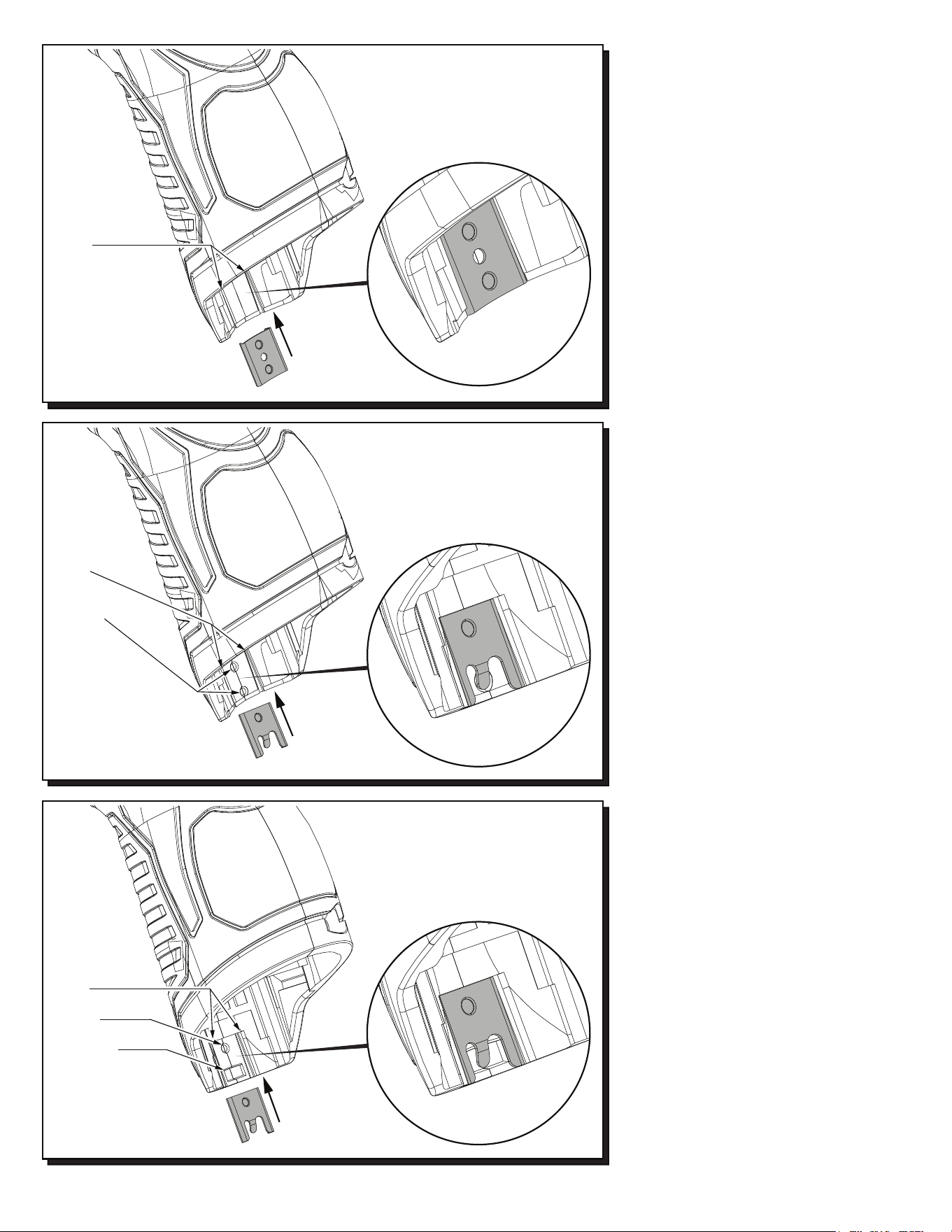
42-70-0055
42-70-0058
42-70-0058
Recess in early handle
sets may only have the
slots to accommodate a
housing clip. Use 42-70-0055
only in this situation.
Slots
Recess in newer handle
sets have two slots, a
dimple and a tab cavity to
accommodate the newer
housing clip design.
Slots
Dimple
Tab Cavity
Updated M12™ Handle Sets utilize Housing
Connection Clips No. 42-70-0055 and 42-70-
0058. (The 42-70-0058 is a preferred upgrade).
Install this clip design by aligning the side rails
of the clip with the two slots in the handle set.
Gently push into place with the aid of a small
flat blade screwdriver or a similar instrument.
Be sure that the clip is properly seated in both
slots and that the tab of the clip snaps down in
the round dimpled cavity of the handle set. Be
sure that the clip is flush to sub-flush to the end
of the handle set. To remove the clip, use the
same small flat blade screwdriver or a similar
instrument and lift up on the clip tab while
pushing the clip out of the handle set. Use a
needle nose pliers to gently rebend the clip tab
if necessary. If the tab on the clip is damaged
during this process and is loose or will not stay
in place, replace with a new 42-70-0058 clip.
Early M12™ Handle Sets utilize Housing
Connection Clip No. 42-70-0055. Install this
clip design by aligning the side rails of the clip
with the two slots in the handle set. Gently
push into place with the aid of a small flat
blade screwdriver or a similar instrument. Be
sure that the clip is properly seated in both
slots and that the clip is flush to sub-flush to
the end of the handle set. To remove the clip,
use the same small flat blade screwdriver or a
similar instrument and push the clip out of the
handle set. If the clip is loose or will not stay in
place, a needle nose pliers can be used to
gently bend/pinch the side rails of the clip. If
the clip is damaged do not use, replace with a
new 42-70-0055 housing clip.
Slots
Dimples
Recess in this
handle set design
has slots and dimples
to secure a housing clip.
The 42-70-0055 can be
used but the 42-70-0058 is
preferred in this situation.
Newer M12™ Handle Sets utilize Housing
Connection Clip No. 42-70-0058. Install this
clip design by aligning the side rails of the clip
with the two slots in the handle set. Gently
push into place with the aid of a small flat blade
screwdriver or a similar instrument. Be sure
that the clip is properly seated in both slots and
that the tab of the clip snaps down in the
rectangular cavity of the handle set. Be sure
that the clip is flush to sub-flush to the end of
the handle set. To remove the clip, use the
same small flat blade screwdriver or a similar
instrument and lift the clip tab out of the cavity
while pushing the clip out of the handle set.
Use a needle nose pliers to gently rebend the
clip tab if necessary. If the tab on the clip is
damaged during this process and is loose or
will not stay in place, replace with a new
42-70-0058 clip.
9
10
11
12
13
3
3
2
2
1
1
4
4
8
8
7
6
5
5
6
7
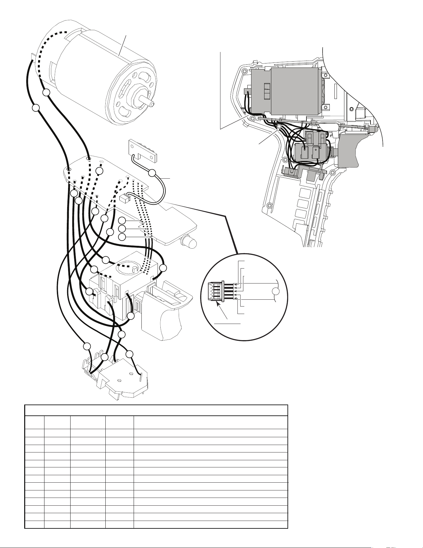
Terminals, Connectors and 1 or 2 End Wire Preparation
Wire
Color
Origin or
Gauge
Wire
No.
Length
WIRING SPECIFICATIONS
1 Black 23-30-0590 ----- Component of the motor assembly.
2 Red 23-30-0590 ----- Component of the motor assembly.
3 White 23-66-2735 ----- Component of the switch assembly.
4 Black 23-66-2735 ----- Component of the switch assembly.
5 Black 23-66-2735 ----- Component of the switch assembly.
6 Red 23-66-2735 ----- Component of the switch assembly.
7 White 23-66-2735 ----- Component of the switch assembly.
8 Red 23-66-2735 ----- Component of the switch assembly.
9 Red 23-66-2735 ----- Component of the switch assembly.
10 Yellow 23-66-2735 ----- Component of the switch assembly.
11 Blue 23-66-2735 ----- Component of the switch assembly.
12 Black 23-66-2735 ----- Component of the switch assembly.
13 Sleeve 23-66-2735 ----- Component of the switch assembly / fuel gauge LED.
MOTOR
ASSEMBLY
FUEL GUAGE
LED ASSY.
SLEEVED WIRES
(White, black, red,
green and gray)
ROUTE WIRES 1 AND 2
THROUGH TRAPS IN
THIS AREA.
WIRE TIE
FOR 2, 5 & 6
AS AN AID TO REASSEMBLY, TAKE NOTICE OF WIRE ROUTING AND
POSITION IN WIRE GUIDES AND TRAPS WHILE DISMANTLING TOOL
BE CAREFUL AND
AVOID PINCHING
WIRES BETWEEN
HANDLE HALVES
WHEN ASSEMBLING.
WHITE
BLACK
RED
GREEN
GRAY
13
PINNED SIDE OF CONNECTOR
TO FACE DOWN WHEN
INSTALLING TO
PC BOARD
NOTE:
POSITION CONNECTOR PORTION
OF #13 WITH OPEN PINNED SIDE
FACING DOWN TOWARDS THE
PCB (WHITE WIRE SHOULD FACE
FRONT OF TOOL). BE SURE THAT
THE CONNECTOR IS FULLY SEATED.
PCB
CONNECTOR
BLOCK
ASSEMBLY
SWITCH
ORIENT MOTOR ASSEMBLY
WITH SLOT TO THE TOP