
12
15
3
11
22
13
16
7
6 5 19
1
2
23
4
10
14
8
38
18
2x
7x
4x
4x
4x
35
25
6 18 19
38 89
9
12 15
16 17
24
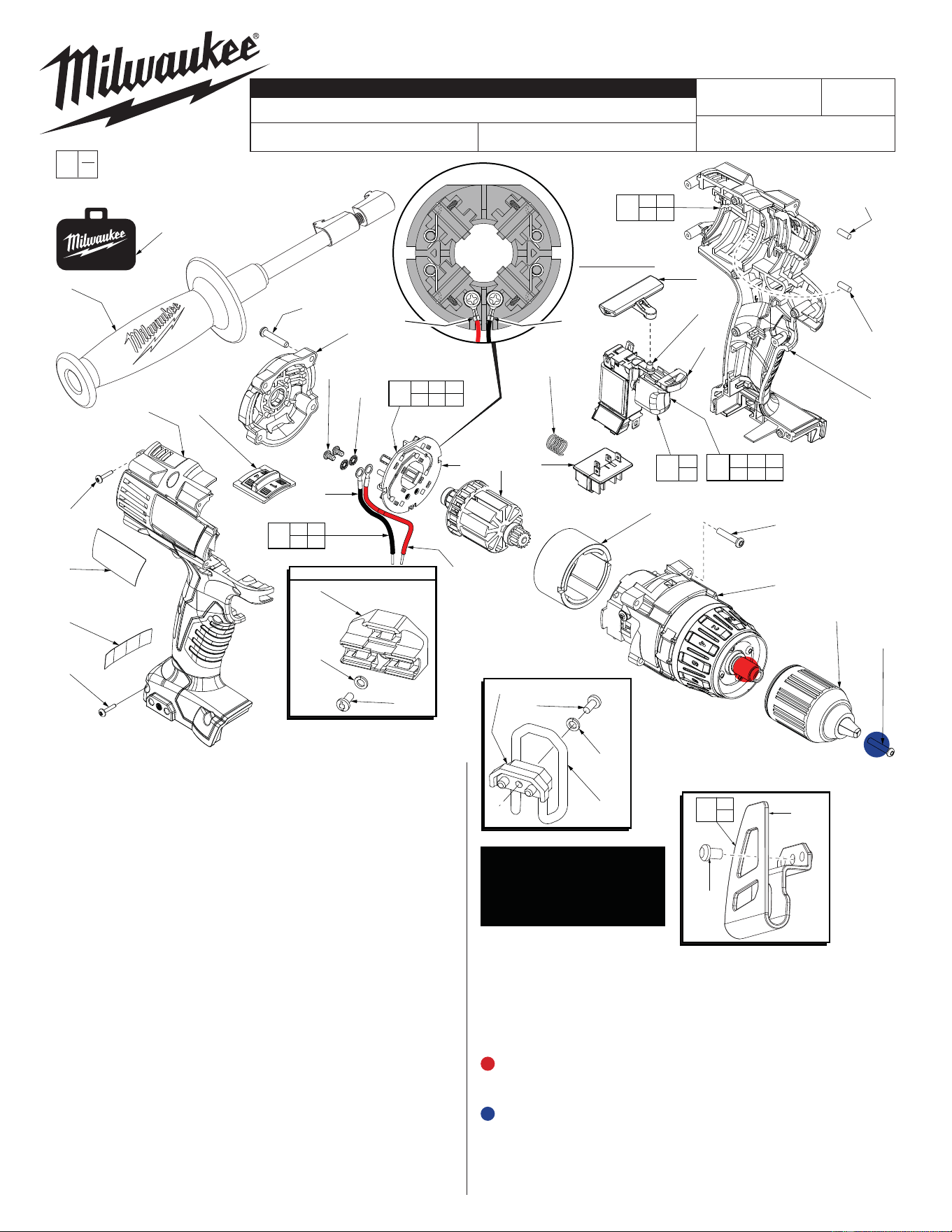
Rubber Slugs (12)-
Quantity of 4,
two in each
handle half
S
= Optional, Not
Standard Equipment
31
32
33
S
S
S
BIT HOLDER, OPTIONAL
S
33
32
34
S
S
S
Belt Clip No. 42-70-5150
S
9
24
90
80
81
82
81
82
There are 2 belt clip designs
for this tool. The inital design,
Belt Clip #34, 42-70-5150 is
being discontinued and re-
placed by Belt Clip Assembly
#80, 42-70-2653.
Brush Card Assy.
L
85 86
88
87
86
85
85 86
87 88
89
6 85 86
87 88
91
14
17
MILWAUKEE ELECTRIC TOOL CORPORATION
13135 W. Lisbon Road, Brookfi eld, WI 53005
Drwg. 16
BULLETIN NO.
54-06-2620
SERVICE PARTS LIST
FIG. PART NO. DESCRIPTION OF PART NO. REQ.
1 05-88-1500
M6 x 1.0 LH Chuck Screw w/ locking patch
(1)
2 42-66-0755 1/2” Chuck (1)
3 06-82-2025 M3.5 Handle Screw T-10 (7)
4 18-01-3026 Service Field (1)
5 16-01-3025 Service Armature Assembly (1)
6 --------------- Brush Card (1)
7 45-24-0675 High / Low Shifter (1)
8 42-42-0800 Forward / Reverse Button (1)
9 23-66-0273 Switch Assembly (1)
10 40-50-1090 Compression Spring (1)
11 10-20-2695 Warning Label (1)
12 45-30-0255 Rubber Slug (4)
13 06-82-6350 M3 x 16mm Handle Screw T-10 (2)
14 05-88-1710 M3.5 x 22mm End Cap/Gearcase Scr T-10 (8)
15 --------------- Left Handle (1)
16 --------------- Right Handle (1)
17 42-52-0390 End Cap (1)
18 --------------- LED Assembly (1)
19 --------------- Terminal Block Assembly (1)
22 12-20-2610 Service Nameplate Kit (1)
23 14-29-0305 Service Gearcase Assembly (1)
24 31-44-2611 Service Housing Kit (1)
25 42-62-0526 Side Handle Assembly (1)
31 43-72-0550 Bit Holder, Optional (1)
32 05-90-0225 M4 Spring Washer, Optional (1)
33 06-82-5275 6-32 x 5/16” Pan Hd. T-15 Screw, Optional (2)
34 42-70-5150 Belt Hook, Optional (1)
35 42-55-2611 Carrying Case (1)
38 --------------- Switch (1)
80 42-70-2653 Belt Clip Assembly (1)
81 --------------- Belt Clip (1)
82 --------------- Belt Clip Screw (1)
85 --------------- Red Leadwire Assembly (1)
86 --------------- Black Leadwire Assembly (1)
CATALOG NO. 2610-20
REVISED BULLETIN
SPECIFY CATALOG NO. AND SERIAL NO. WHEN ORDERING PARTS
M18™ MAGNUM 1/2" DRIVER-DRILL
STARTING
SERIAL NO.
DATE
Aug. 2014
WIRING INSTRUCTION
B53A
EXAMPLE:
Component Parts (Small #) Are Included
When Ordering The Assembly (Large #).
0
00
SEE PAGE 3
*
*
See page 2 for
instructions
= Apply Red Loctite
®
thread locking sealant or the equivalent
to the threads of the gearcase spindle (23) before securing
chuck to that spindle. Torque to 550-600in/lbs (45-50ft/lbs).
= Apply Blue Loctite
®
thread locking sealant or the equivalent
to the threads of the chuck screw (1) before securing chuck
to the gearcase spindle. Torque to 90-100in/lbs
FIG. PART NO. DESCRIPTION OF PART NO. REQ.
87 05-88-0928 M3 x 5mm Pan Hd. T-10 Screw (2)
88 45-88-1980 Spring Washer (2)
89 14-46-2395 Leadwire/Screw/Washer Kit (1)
90 23-66-2611 Switch/Handle Service Kit (1)
91 14-46-2018 Brush Card Assembly (1)
Two brush
card designs
See page two
L
Soldered-
Original design
Screwed-
New design
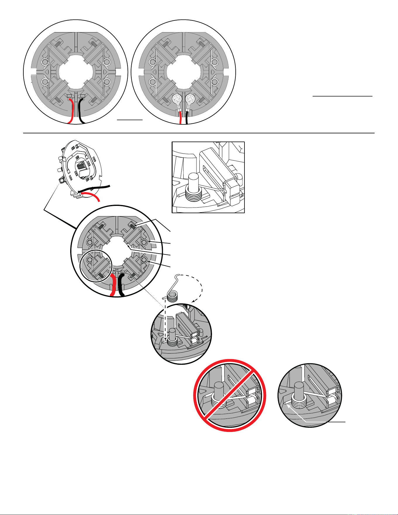
Back View
Brush Card Assemblies
NOTE:
There are two Brush Card Assembly designs.
On the original brush card design the red and black wires
that go to the switch are soldered on the brush card.
On the new brush card design the red and black wires
that go to the switch are secured to the brush card with
spring washers and screws.
The new brush card design is directly interchangeable
in tools that have the old brush card design.
Be sure carbon
brush is in brush tube
with brush shunt moving
freely in side groove of tube.
Place brush spring over post with short leg
positioned downward as shown. Be sure spring
is completely down with short leg trapped against
'Y' shaped wall on brush card.
While holding spring in place, bring the long leg of
spring over the brush tube and through rear opening
of tube. Position rounded hook of spring in groove on
back of carbon brush. Be sure to check for free move-
ment between carbon brush, brush shunt and brush spring.
Brush Card Assy.
Brush Shunt (4 places)
Right Brush Spring (2x)
Carbon Brush (4x)
Left Brush Spring (2x)
Red
Black
CorrectWrong
Short leg of
spring to the
bottom
NOTE:
As an aid to prevent damage to the armature
commutator or the brushes when removing and
installing the armature assembly, it is recommended to
pull the carbon brushes partially back into the brush
tube. The carbon brushes will be held in place with the
brush spring moving from the rear of the brush to the
side of the brush.
In the unlikely event that the spring pops off follow the
instructions below.
2
1
3
4
5
6
7
9
8
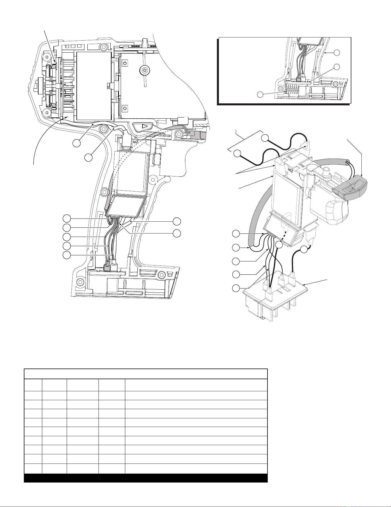
Red
Black
Black
Red
Green
Gray
Red
Black
White
BRUSH CARD
1
9
8
3
4
5
6
7
Gray
Green
Red
Black
White
Black
Red
Black
LED ASSEMBLY
TERMINAL
BLOCK
SWITCH
From Brush Card
Assembly
2
Red
Add Heat Shrink
Tubing Over
Soldered Terminals
1 Black ----- ----- Component of the Brush Card Assembly.
2 Red ----- ----- Component of the Brush Card Assembly.
3 Green ----- ----- Component of the LED Assy./Switch Assembly.
4 Gray ----- ----- Component of the LED Assy./Switch Assembly.
5 Red ----- ----- Component of the LED Assy./Switch Assembly.
6 Black ----- ----- Component of the LED Assy./Switch Assembly.
7 White ----- ----- Component of the LED Assy./Switch Assembly.
8 Black ----- ----- Component of the Switch Assembly.
9 Red ----- ----- Component of the Switch Assembly.
Terminals, Connectors and 1 or 2 End Wire Preparation
Wire
Color
Origin or
Gauge
Wire
No.
Length
WIRING SPECIFICATIONS
BULK LEAD WIRE - BULLETIN NO. 58-01-0003
Watch for pinched
wires in this area.
NOTE:
Compression spring (10)
is positioned between the
bottom/back of the left
housing half (15) and the
back of the terminal
block assembly (19)
as shown.
*
10
15
19