
BULLETIN NO.
54-06-2613
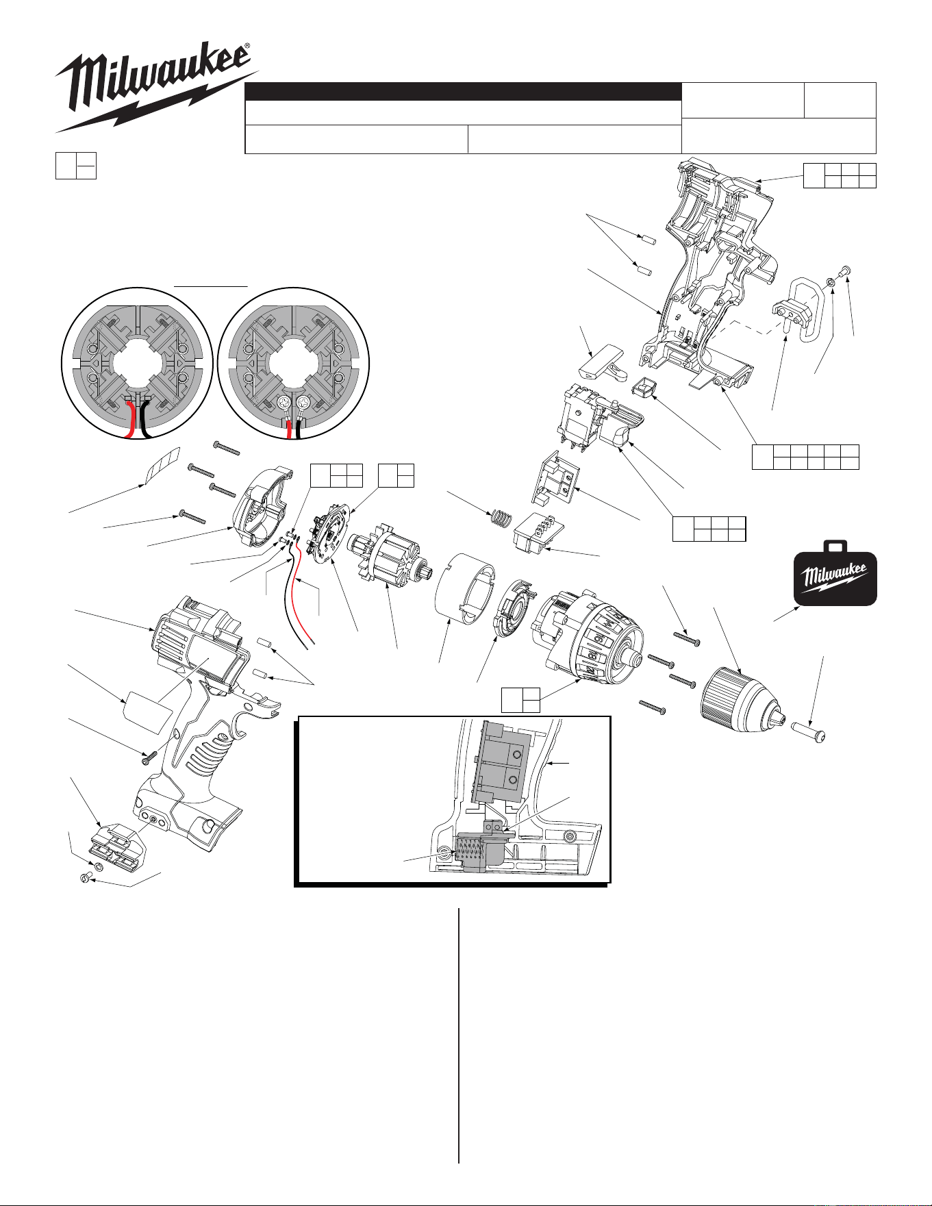
SERVICE PARTS LIST
CATALOG NO. 2601-20
REVISED BULLETIN
54-06-2612
SPECIFY CATALOG NO. AND SERIAL NO. WHEN ORDERING PARTS
1/2" Compact Driver Drill
STARTING
SERIAL NO.
WIRING INSTRUCTION
B28D
See Page 3
DATE
Aug. 2014
MILWAUKEE ELECTRIC TOOL CORPORATION
13135 W. Lisbon Road, Brookfi eld, WI 53005
Drwg. 2
FIG. PART NO. DESCRIPTION OF PART NO. REQ.
1 05-88-1500 M6 x 1 LH Chuck Screw (1)
2 06-82-7236
#4-20 x .625 Pan Hd. Plast. T-10 Screw
(6)
3 06-82-7336
#4-20 x .750 Pan Hd. Plast. T-10 Screw
(8)
4 --------------- Switch (1)
5 48-66-1275 Keyless Chuck Assembly (1)
6 10-20-2695 Warning Label (1)
7 12-20-0800 Service Nameplate (1)
8 --------------- Brush Card (1)
9 18-01-3020 Service Field (1)
10 16-01-3000 Service Armature Assembly (1)
11 --------------- LED Assembly (1)
12 --------------- Terminal Block Assembly (1)
14 --------------- PCB Assembly (1)
15 28-14-0662 Gearcase Assembly (1)
16 --------------- Handle Halve-Left (1)
17 --------------- Handle Halve-Right (1)
18 31-44-2600 Handle Halve Set (1)
19 40-50-1090 Compression Spring (1)
20 --------------- Housing End Cap (1)
EXAMPLE:
Component Parts (Small #) Are Included
When Ordering The Assembly (Large #).
0
00
FIG. PART NO. DESCRIPTION OF PART NO. REQ.
21 --------------- Motor Mount (1)
22 45-24-0910 Forward/Reverse Shuttle (1)
23 45-30-0255 Rubber Slug (4)
24 23-66-1233 Switch Assembly (1)
25 23-66-1232 Switch and Handle Halve Assembly (1)
28 48-55-0960 Accessory Carrying Case (1)
29 06-82-5275
6-32 x 5/16" Pan Hd. T-15 Screw, Optional
(2)
30 42-70-5150 Belt Hook, Optional (1)
31 43-72-0550 Bit Holder, Optional (1)
32 05-90-0225 Washer, Optional (2)
72 05-88-0928 M3 x 5mmPan Hd. T10 Screw (2)
73 45-88-1980 Spring Washer (2)
74 --------------- Leadwire Assembly - Red (1)
75 --------------- Leadwire Assembly - Black (1)
76 14-46-2399 Leadwire/Screw/Washer Kit (1)
77 14-46-2012 Brush Card Assembly (1)
= Part number change from
previous service parts list.
*
S
S
S
S
S
S
S
= Optional,
Not standard
equipment
32
29
17
7
2
31
32
29
2 3 16
17 20 23
18
21
15
2 4 8 11 12
14 16 17 23 76
25
4 8 11
12 14 76
24
NOTE:
Compression spring (19)
is positioned between the
bottom/back of the left
housing half (16) and the
back of the terminal
block assembly (12)
as shown.
*
19
16
12
*
23
16
22
20
6
3
(4x)
10
19
9
21
12
3
5
28
1
23
14
4
11
30
8
74
75
72
(2x)
73
(2x)
77
8
76
76
72 73
74 75
L
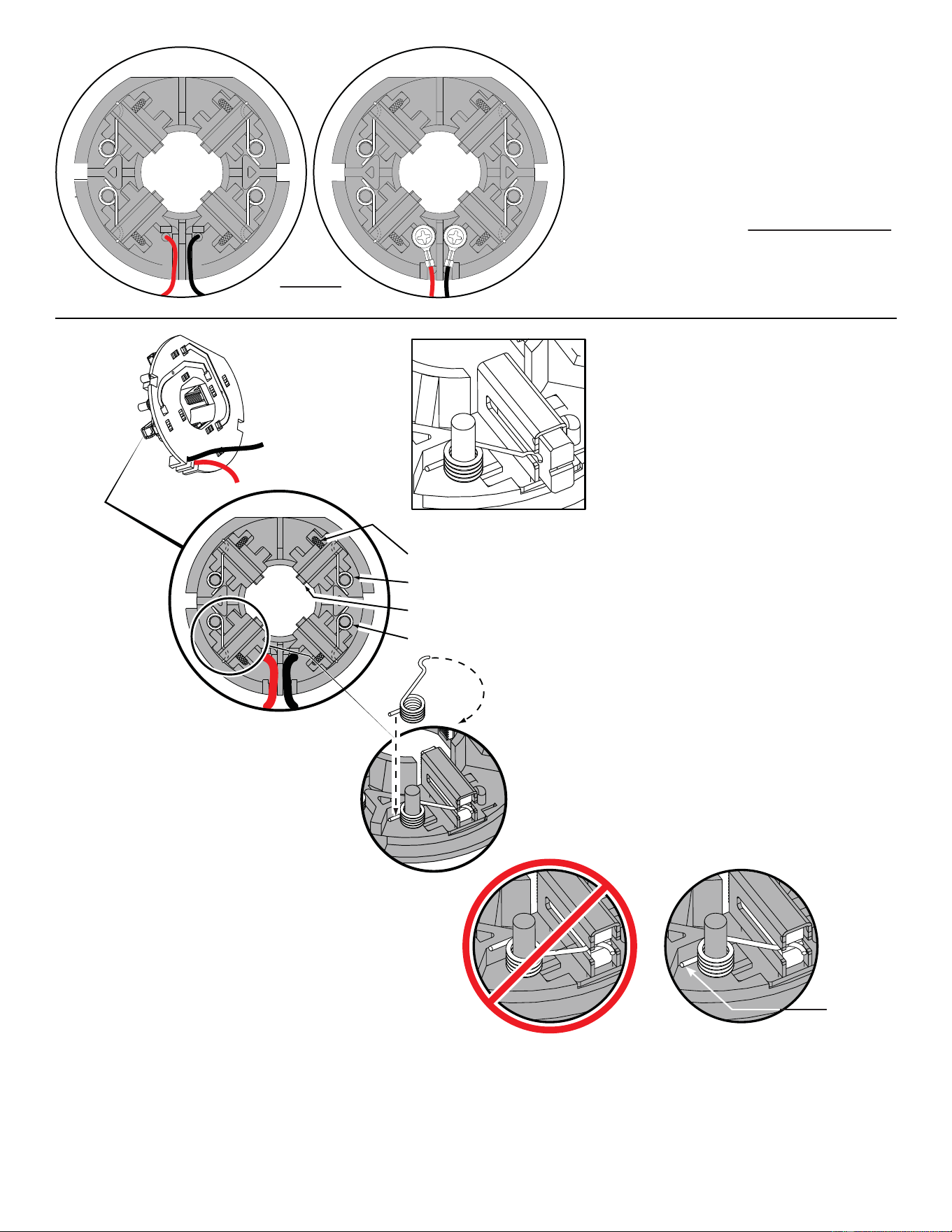
Soldered Screwed
#77 Two styles of Brush Card Assemblies
See page two
L
Soldered-
Original design
Screwed-
New design
Back View
Brush Card Assemblies
NOTE:
There are two Brush Card Assembly designs.
On the original brush card design the red and black wires
that go to the switch are soldered on the brush card.
On the new brush card design the red and black wires
that go to the switch are secured to the brush card with
spring washers and screws.
The new brush card design is directly interchangeable
in tools that have the old brush card design.
Be sure carbon
brush is in brush tube
with brush shunt moving
freely in side groove of tube.
Place brush spring over post with short leg
positioned downward as shown. Be sure spring
is completely down with short leg trapped against
'Y' shaped wall on brush card.
While holding spring in place, bring the long leg of
spring over the brush tube and through rear opening
of tube. Position rounded hook of spring in groove on
back of carbon brush. Be sure to check for free move-
ment between carbon brush, brush shunt and brush spring.
Brush Card Assy.
Brush Shunt (4 places)
Right Brush Spring (2x)
Carbon Brush (4x)
Left Brush Spring (2x)
Red
Black
CorrectWrong
Short leg of
spring to the
bottom
NOTE:
As an aid to prevent damage to the armature
commutator or the brushes when removing and
installing the armature assembly, it is recommended to
pull the carbon brushes partially back into the brush
tube. The carbon brushes will be held in place with the
brush spring moving from the rear of the brush to the
side of the brush.
In the unlikely event that the spring pops off follow the
instructions below.
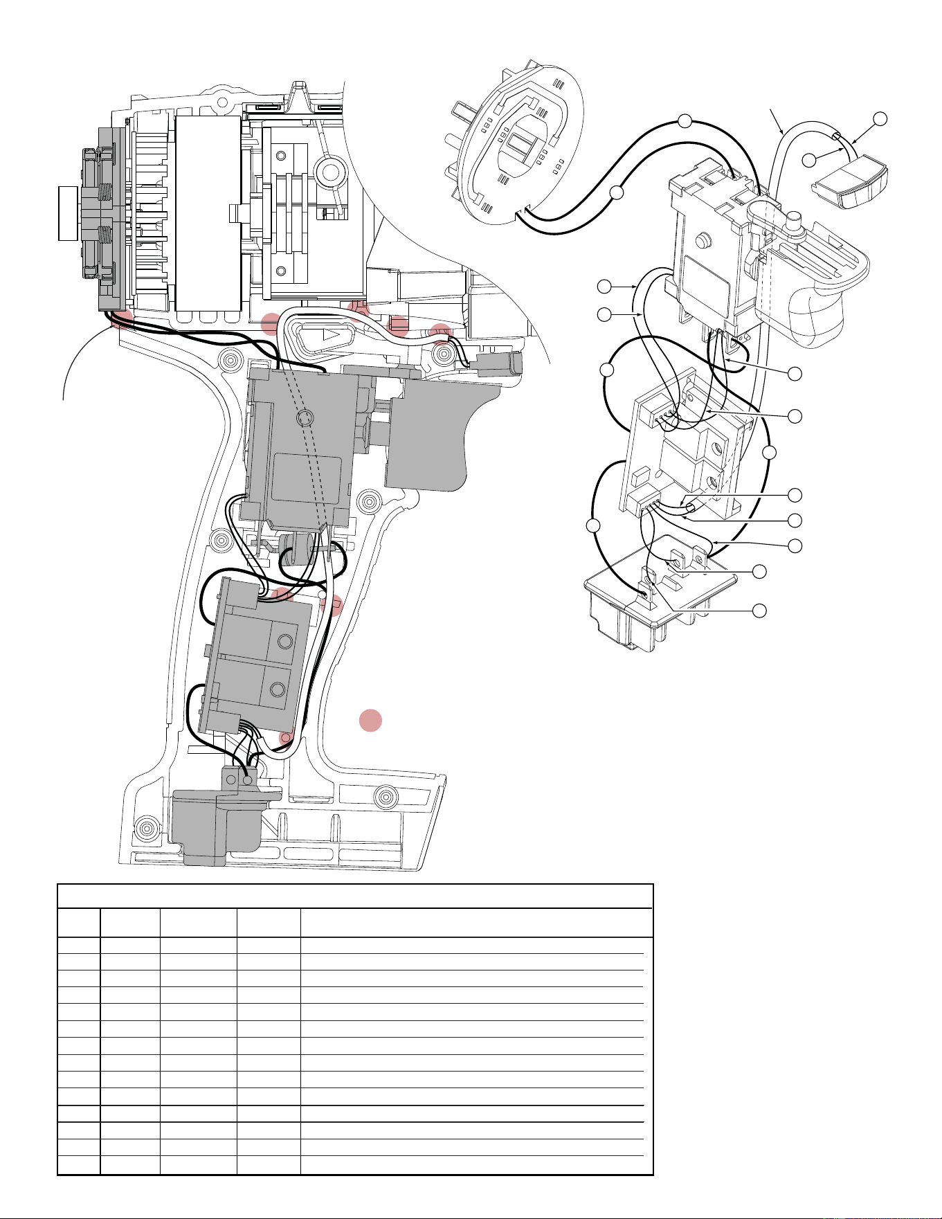
= WIRE TRAPS
Watch for pinched
wires in this area.
13
3
4
5
2
1
14
13
14
12
11
10
7
9
6
8
Sleeve
Black
Blue
Orange
White
Black
Blue
Red
Yellow
Blue
Red
Brown
Green
BRUSH CARD
ASSEMBLY
LED
SWITCH
PCBA
TERMINAL
BLOCK
ASSEMBLY
1 Black ----- ----- Component of Brush Card Assy. Connect to M2 on Switch.
2 Red ----- ----- Component of Brush Card Assy. Connect to M1 on Switch.
3 Red ----- ----- Component of Switch/Brush Card/Terminal Block Assembly.
4 Black ----- ----- Component of Switch/Brush Card/Terminal Block Assembly.
5 Blue ----- ----- Component of Switch/Brush Card/Terminal Block Assembly.
6 Orange ----- ----- Component of Switch/Brush Card/Terminal Block Assembly.
7 Green ----- ----- Component of Switch/Brush Card/Terminal Block Assembly.
8 White ----- ----- Component of Switch/Brush Card/Terminal Block Assembly.
9 Brown ----- ----- Component of Switch/Brush Card/Terminal Block Assembly.
10 Black ----- ----- Component of Switch/Brush Card/Terminal Block Assembly.
11 Blue ----- ----- Component of Switch/Brush Card/Terminal Block Assembly.
12 Red ----- ----- Component of Switch/Brush Card/Terminal Block Assembly.
13 Blue ----- ----- Component of Switch/Brush Card/Terminal Block Assy. (LED)
14 Yellow ----- ----- Component of Switch/Brush Card/Terminal Block Assy. (LED)
Terminals, Connectors and 1 or 2 End Wire Preparation
Wire
Color
Origin or
Gauge
Wire
No.
Length
WIRING SPECIFICATIONS
Model 2602-20 is shown.
Wire routing and placement in left handle half
is the same for model 2601-20