
Technical Support and E-Warranty Certificate
www.vevor.com/support
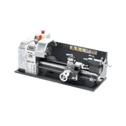
LATHE INSTRUCTION MANUAL
MODEL:L2035
We continue to be committed to provide you tools with competitive price.
"Save Half", "Half Price" or any other similar expressions used by us only
represents an estimate of savings you might benefit from buying certain tools with us
compared to the major top brands and doses not necessarily mean to cover all
categories of tools offered by us. You are kindly reminded to verify carefully when
you are placing an order with us if you are actually saving half in comparison with
the top major brands.

- 1 -
Have product questions? Need technical support? Please feel free to
contact us:
CustomerService@vevor.com
NEED HELP? CONTACT US!
This is the original instruction, please read all manual instructions
carefully before operating. VEVOR reserves a clear interpretation of our
user manual. The appearance of the product shall be subject to the
product you received. Please forgive us that we won't inform you again if
there are any technology or software updates on our product.
LATHE
MODEL:L2035

- 2 -
QUALITY ASSURANCE
MATTERS NEEDING ATTENTION
The information contained in this handbook is intended as a guide to the
operation of these machines and does not form part of any contract .The
data it contains has been obtained from the machine manufacturer and
from other sources. We strive to ensure the accuracy of this information
and try to verify each item and each data, but we cannot guarantee the full
accuracy of the information, which means that the equipment supply may
differ in detail from the description of the instructions. Furthermore,
development of the machine may mean that the equipment supplied may
differ in detail from the descriptions herein. The responsibility therefore lies
with the user to satisfy himself that the equipment or process described is
suitable for the purpose intended.
We will make every effort to ensure the quality of our products, and we
promise to consumers that we will guarantee our products for one year,
except for machine damage caused by improper operation of customers,
and accidents resulting therefrom, or abnormal wear and damage caused
by lack of maintenance.
In order to fulfill the warranty commitment, the product or part with quality
problems, please return to us for verification, postage prepaid. Goods sent
back should be accompanied by a note of the date of purchase and a
written explanation of the quality of the product. After our inspection and
confirmation, we will repair or replace their products, or refund the
payment; If we fail to provide repair or replacement in a timely manner, we
shall bear the costs arising from the repair or replacement of the products;
If the damage is not due to the quality of the product, but due to the user's
improper operation or other reasons, the cost shall be borne by the
customer .

- 3 -
SAFETY WARNING
Our company reserves the right to make changes to this specification and
product specifications. We will make continuous efforts to improve the
quality of our products.
All rights reserved. Reproduction or reproduction is not allowed without
permission.
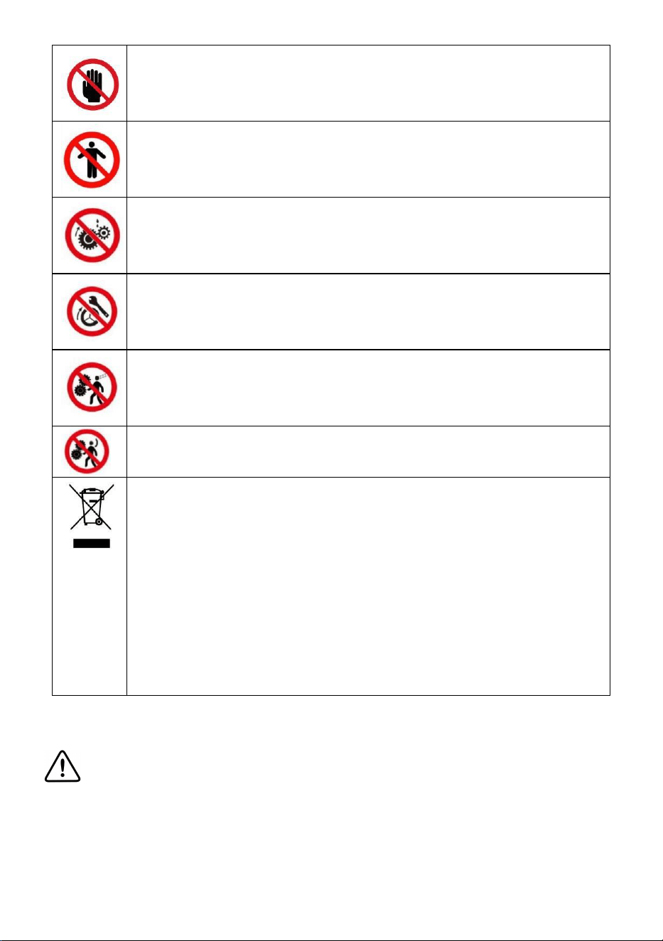
Symbol
Symbol
Description
Warning - To reduce the risk of injury, user must read instructions
manual carefully.
This symbol, placed before a safety comment, indicates a kind
of precaution, warning, or danger. Ignoring this warning may
lead to an accident. To reduce the risk of injury, fire, or
electrocution, please
always follow the recommendation shown below.
Danger!
Risk of personal injury or environmental damage! Risk of
electric shock! Risk of personal injury by electric shock!
Alternating current
Beware of clamping
Warning- Be sure to wear ear protectors when using this product.
Warning- Be sure to wear eye protectors when using this product.
- 4 -
Do not put your hands into safety guard when machine is working
No entry automatic machinery in operation Authorized personnel
only
Do not fill oil during operation
Do not turn during repair
No fatigue operation
The operation is no phone calls
Disposal information:
This product is subject to the provision of European Directive
2012/19/EC. The symbol showing a wheelie bin crossed
through indicates that the product requires separate refuse
collection in the European Union. This applies to the product
and all accessories marked with this symbol. Products marked
as such may not be discarded with normal domestic waste,
but must be taken to a collection point for recycling electrical
and electronic devices
WARNING: Read all safety warnings, instructions, illustrations and
specifications provided with this machine. Failure to follow all instructions
listed below may result in electric shock, fire and/or serious injury.
Save all warnings and instructions for future reference.

- 5 -
The machine tool should be used by experienced personnel. If you are not
familiar with the operation process of the lathe, do not use the machine
tool at will. Use the instructions before operating.
1. Before starting the machine tool, the safety cover should be in the
correct position.
2. Before starting the machine tool, please check whether the tool rest
wrench and chuck key are removed.
3. Prevent the machine from starting accidentally. Turn off the motor
power before clamping the workpiece or tool.
4. Don't force cut. Cutting according to the set cutting speed, cutting
depth and feed speed.
5. Use the right tools. Use the correct tool or workpiece for machining.
Keep the tool sharp and clean to ensure normal and safe operation.
6. Lubricate and replace accessories regularly.
7. Before adjusting or repairing the machine, be sure to disconnect the
power supply.
8. Please check the safety performance of the machine before starting it.
9. Check the performance of all moving parts. All parts must be installed
correctly. Damaged parts must be repaired promptly.
10. When the machine is running, the operator shall not leave.
11. Keep the working place clean, dirty working environment is easy to
lead to accidents.
12. Do not use the machine in dangerous environment.
Do not work in damp places. Ensure that electrical components are
protected from moisture. Keep good lighting.
13. Children are prohibited from entering the work site, and non-operating
personnel should keep a safe distance from the work area.
14. To keep children out of the work area. The door should be locked
when leaving the workshop.
15. Dress appropriately. Don't wear loose clothing, gloves, ties, rings,
bracelets, jewelry, etc. To be on the safe side, For the sake of safety,
wearing non-slip shoes. If you have long hair, please wear a work hat.
16. Wear protective glasses when operating.
17. Pay attention to where you stand and keep your balance at all times.
18. Do not place your hands near the moving parts of the machine.

- 6 -
19. Do not perform any setting operations while the machine is running.
20. Read and understand all warning signs posted on the machine.
21. This manual is intended only to familiarize customers with the
operation of the machine and is not a training manual.
22. Please obey these warnings or serious injury may result.
23. The machine will produce some harmful chemicals in the work of dust,
sawing, grinding and drilling produced by grinding. To reduce the
harm of these chemicals, please work in a well-ventilated place and
wear safety devices. Such as particulate filter masks.

- 7 -
TECHNICAL PARAMETER
Type number
L2035
Capacities
Swing over Bed
204mm
Swing over Cross Side
134mm
Height of spindle center
102mm
Distance Between Centers
350mm
Width of Bed
90mm
Headstock
Hole Through Spindle
20mm
Taper in Spindle Nose
MT3
Diameter chuck
100mm
Number of Spindle Speeds
4-Variable
Range of Spindle Speeds
0-360,720,1100,2200RPM
Feeding and Threading
Number of Metric Threads
9
Range of Metric Threads
0.5~2.5mm
Number of ImperiaI Threads
18
Range of ImperiaI Threads
12~52T.P.I.
Range of Longitudinal Feed
0.1~0.20mm/r
Range of Transversal Feed
0.02~0.20mm/r
Lead screw
Φ16-1.5mm
Compound and Carriage
Tool Post Type
4way
Maximum Compound Slide Travel
50mm
Maximum Cross Slide Travel
60mm
Maximum Carriage Travel
295mm
tail stock
Tail Stock Spindle Travel
50mm
Taper in Tail stock Spindle
MT2
Miscellaneous
Main Motor
110V~60Hz/220-240V~50Hz,1Ph
/600W,
Length, Width and Height
760×330×340(mm)
Product Weight
N.W:50.3Kg; G.W:58.9Kg
Package Size
820*380*462 mm
The general information given in this specification is not binding.

- 8 -
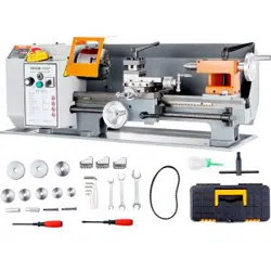
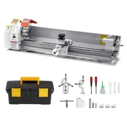
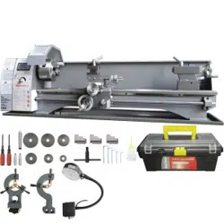
Standard accessories
1. Oil Pan 1
2. Rear Chip Plate 1
3. Three Jaw Chuck 1
4. Specification 1
5. Tool Box 1
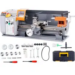
Accessories in the tool box (Fig. 1 )
3 Hand Wheel Lever
1 Dead Center MT2
1 Dead Center MT3
1 Oil Gun
1 Chuck key for the 3-jaw chuck
3 Outside Jaws for the 3-jaw Chuck
5 Hex Wrenches Sets 2.5/3/4/5/6mm
3 Double End Head Wrenches (8/10,12/14,13/16)
8 Change Gear (30T,35T,40T,40T,45T,50T,60T,60T )
1 Philips Screwdriver
1 Flat Head Screwdriver
Special accessories(Accessories that require additional
payment)
Four jaw chuck and back
plate (connecting plate)
Live
Center
Steady
rest Follow
rest
Drill chuck and connecting rod
Fig.1
- 9 -
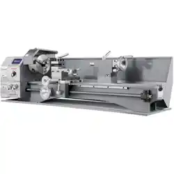
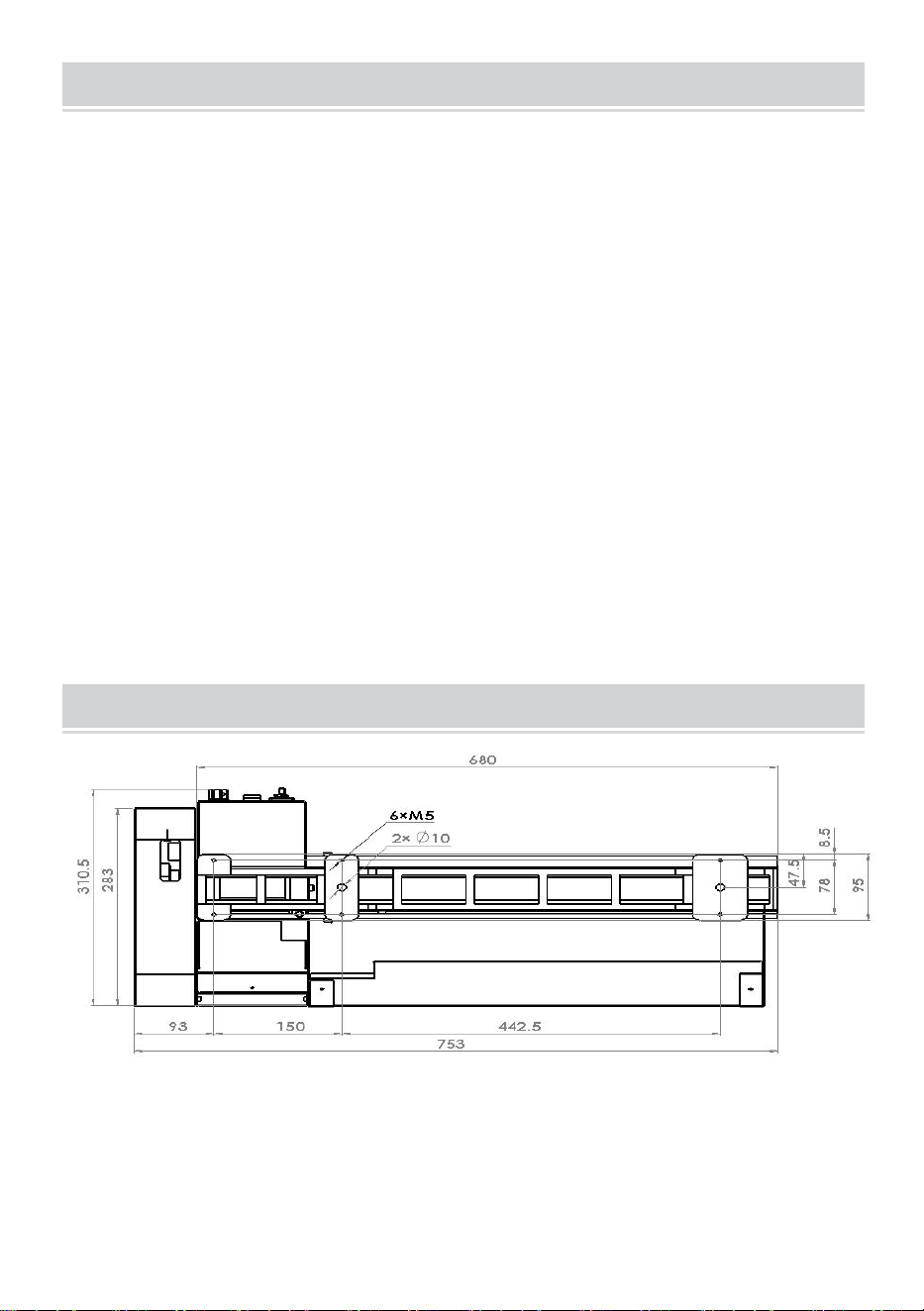
FOUNDATION DRAWING
UNPACKING AND CLEANING
1. Finish removing the wooden crate from around the lathe
2. Check all the accessories of the machine tool according to the
packing list.
3. Unbolt the lathe from the shipping crate bottom.
4. Choose a location for the lathe that is dray, has good lighting and has
enough room to be able to service the lathe on all four sides.
5. With adequate lifting equipment, slowly raise the lathe off the shipping
crate bottom. Do not lift by spindle. Make sure lathe is balanced
before moving to sturdy bench or stand.
6. To avoid twisting the bed, the lathe's location must be absolutely flat
and level. Bolt the lathe to the stand (if used). 1f using a bench,
through bolt for best performance.
7. Clean all rust protected surfaces using a mild commercial solvent,
kerosene or diesel fuel. Do not use paint thinner, gasoline or lacquer
thinner. These will damage painted surfaces. Cover all cleaned
surfaces with a light film of 20W machine oil.
8. Remove the end gear cover. Clean all components of the end gear
assembly and coat all gears with heavy, non-slinging grease.
Fig. 2
- 10 -
General Description
Lathe Bed (Fig. 3)
The lathe bed is made of high-grade iron. By combining high cheeks with
strong cross ribs, a bed of low vibration and rigidity is produced. It
integrates the Headstock and drives the unit, for attaching the carriage
and lead screw. The precision-ground V - sideways, reinforced by heat
hardening and grinding, is the accurate guide for the carriage and tail
stock. The main motor is mounted to the rear of the left side of the bed.
Fig. 3
Headstock (Fig. 4)
The Headstock is cast from high-grade low vibration cast iron .It is bolted
to the bed with four screws .The Headstock houses the main spindle with
two precision taper roller bearings and the drive unit.
The main spindle transmits the torque during the turning process .It also
holds the workpieces and clamping devices. (e.g.3-jaw chuck).
Fig. 4
- 11 -
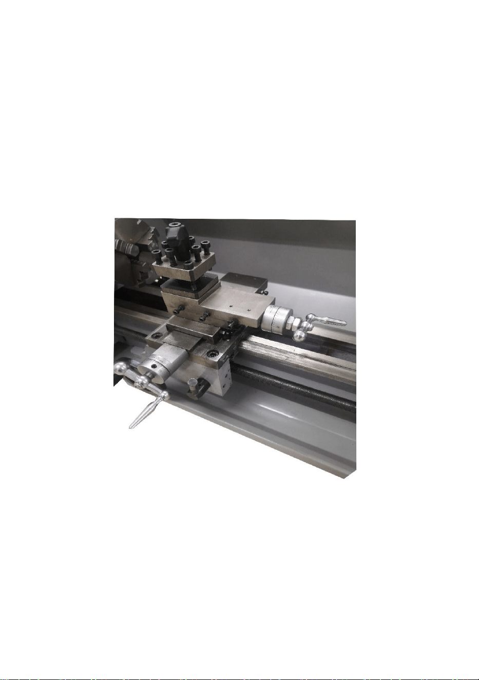
Carriage (Fig. 5)
The carriage is made from high-quality cast iron. The slide parts are
smoothly ground .They fit the V on the bed without play. The lower sliding
parts can be easily and simply adjusted .The cross slide is mounted on the
carriage and moves on a dove-tailed slide Play in the cross slide may be
adjusted with the gibs.
Move the cross slide with its conveniently positioned Hand wheel. There is
a graduated collar on the Hand wheel.
A four way tool post is fitted on the top slide and allows four tools to be
clamped .Loosen the center clamp handle to rotate any of the four tools
into position.
Fig. 5
Fig.5
- 12 -
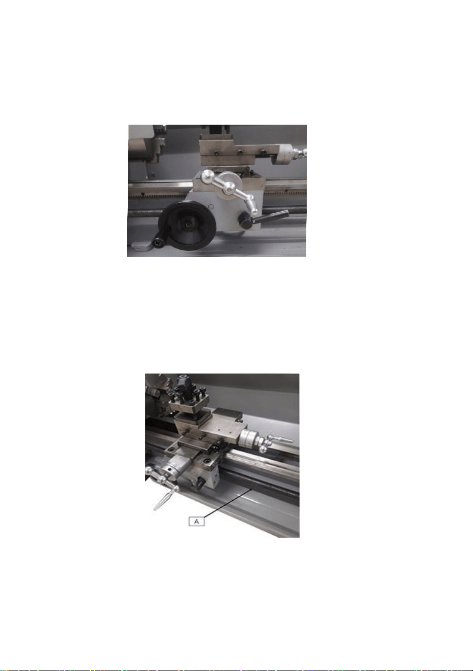
Apron (Fig. 6)
The apron is mounted on the bed. It houses the half nut with an engaging
lever for activating the automatic feed. The half nut gibs can be adjusted
from the outside.
A rack, mounted on the bed, and a pinion operated by Hand wheel on the
carriage allows for quick travel of the apron.
Fig. 6
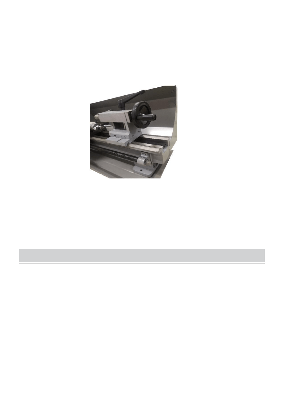
Lead screw (Fig. 7)
The lead screw (A, Fig.7) is mounted on the front of the machine bed. It is
connected to the gear box at the left for automatic feed and is supported
by bearing on both ends.
Fig.7
- 13 -
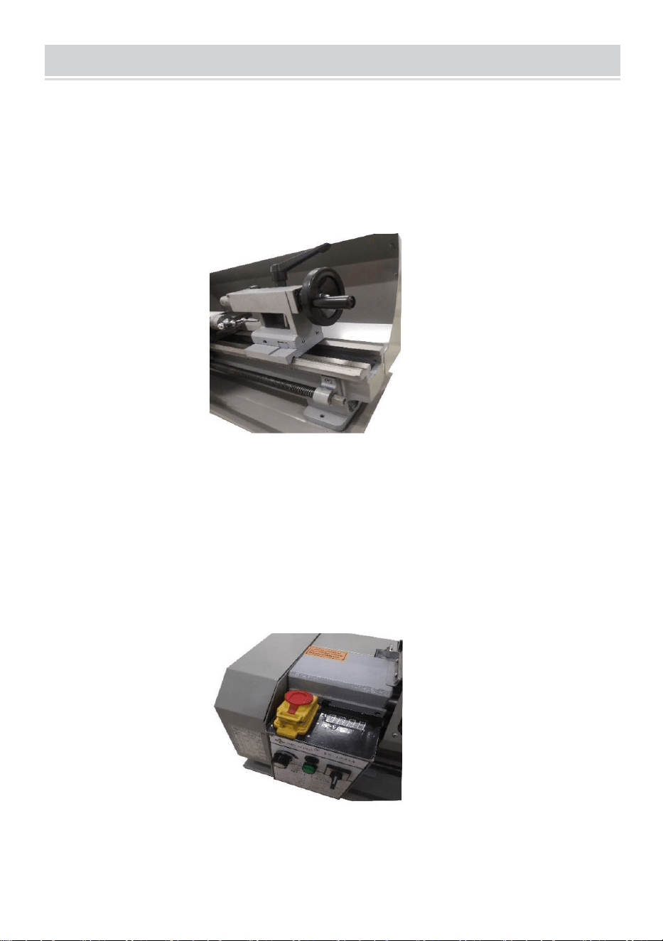
Operating equipment
tail stock (Fig. 8)
The tail stock slides on a V way and can be clamped at any location. The
tail stock has a heavy-duty spindle with a Morse taper No. 2 socket and a
graduated scale. The spindle can be clamped at any location with a
clamping lever. The spindle is moved with a hand wheel at the end of the
tailstock.
Fig.8
Notice:
Fit the securing screw (C, Fig. 8) at the end of the lathe in order to prevent
the tailstock from falling off the lathe bed.
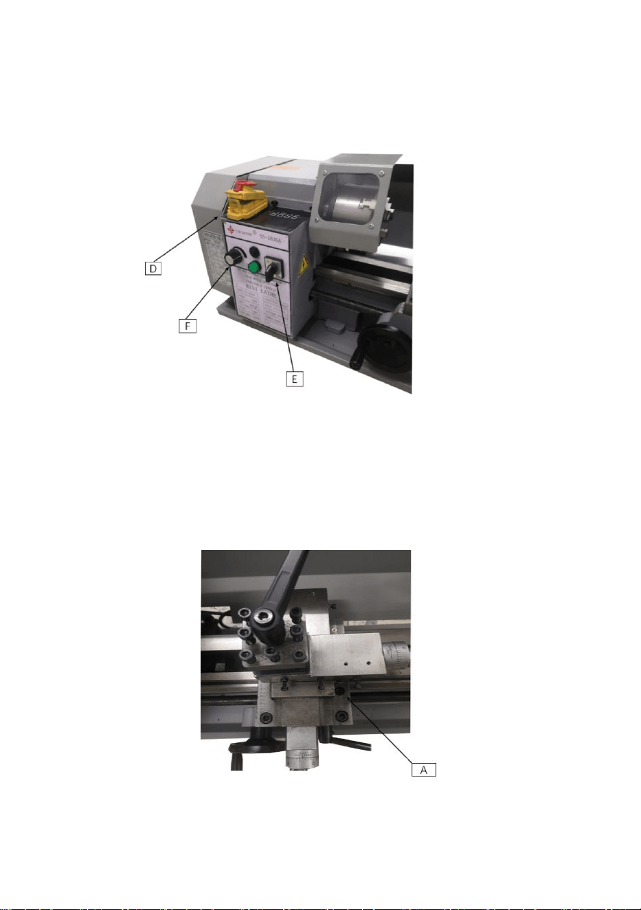
1. Emergency Button: 0N/0FF Switch (D,Fig. 9)
The machine is switched on and off with ON/OFF button. Depress to stop
all machine functions. To restart, lift the cover and press ON button.
2. Change-over Switch(E,Fig. 9)
After the machine is switched on, turn the switch to "F"position for counter-
clockwise spindle rotation(forward). Turn the switch to "R" position for
clockwise spindle rotation(reverse) ."O" position is OFF and the spindle
remains idle.
- 14 -
3. Variable Speed Control Switch (F,Fig. 9)
Turn the switch clockwise to increase the spindle speed. Turn the switch
counter-clockwise to decrease the spindle speed. The possible speed
range is dependent on the position of the drive belt.
Fig. 9
4﹒Carriage Lock
Turn hex socket cap screw (A, Fig. 10) clockwise and tighten to lock. Turn
counter-clockwise and loosen to unlock.
Caution: carriage lock screw must be UN locked before engaging
automatic feeds or damage to lathe may occur.
Fig.10
- 15 -
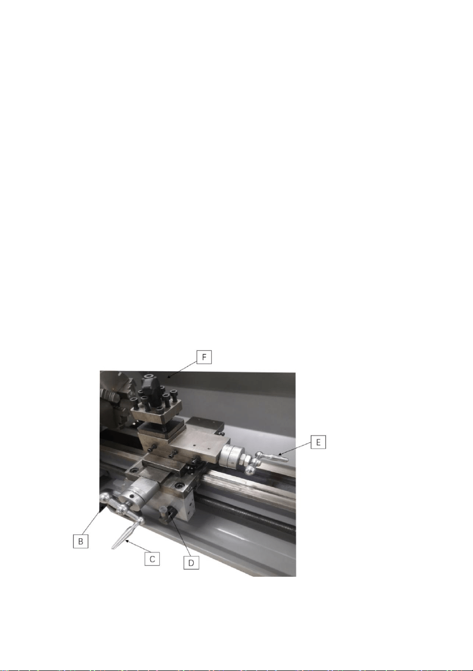
5﹒Longitudinal Traverse Hand wheel (B,Fig.11)
Rotate hand wheel clockwise to move the apron assembly toward
the tail stock (right). Rotate the hand wheel counter-clockwise to
move the apron assembly to ward the Headstock(left).
6﹒Cross Traverse Lever (C,Fig. 11)
Clockwise rotation moves the cross slide toward the rear of the machine.
7﹒Half Nut Engage Lever (D,Fig. 11)
Move the lever down to engage. Move the lever up to disengage.
8﹒Compound Rest Traverse Lever (E,Fig. 11)
Rotate clockwise or counter-clockwise to move or position.
9﹒Tool Post Clamping Lever (F,Fig. 11)
Rotate counter-clockwise to loosen and clockwise to tighten.
Rotate the tool post when the lever is unlocked.
Fig.11
- 16 -
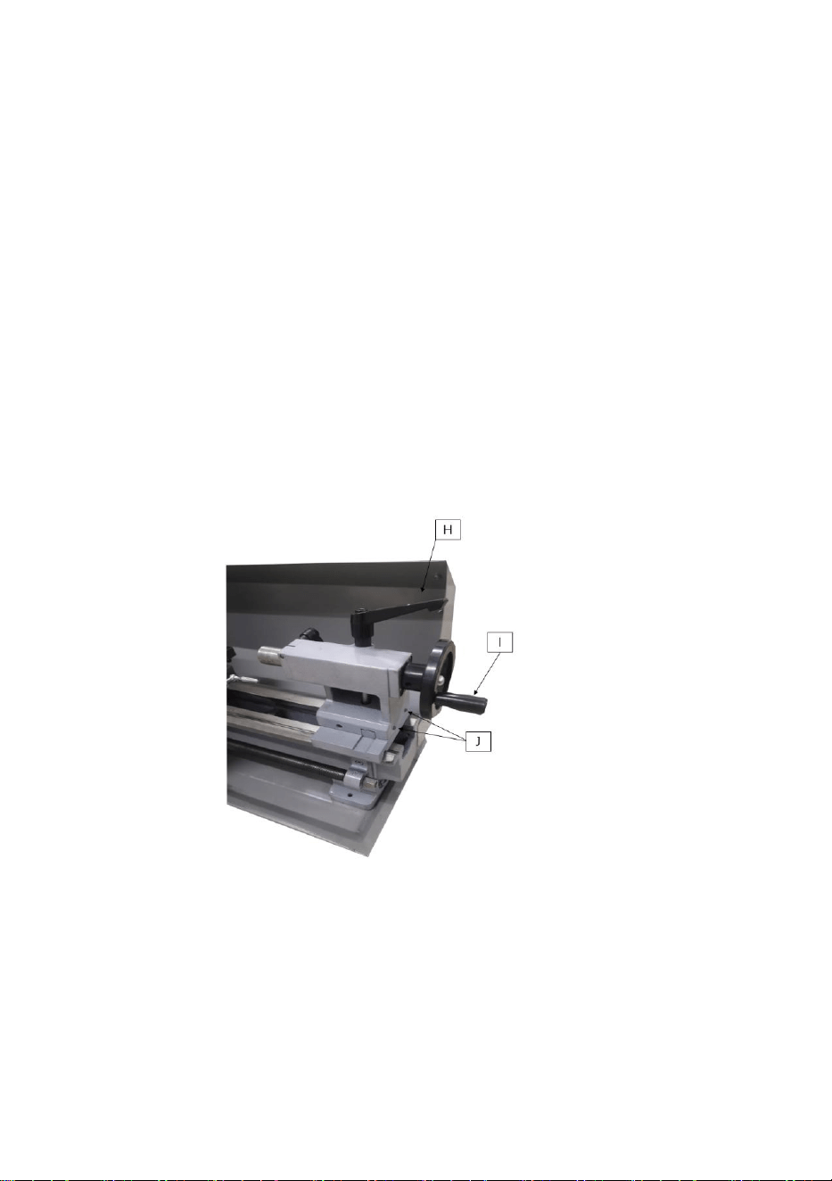
10﹒Tail stock Quill Clamping Lever (H,Fig. 12)
Rotate the lever clockwise to lock the spindle and counter-
clockwise to unlock it.
11﹒Tail stock Quill Traverse Hand wheel (I,Fig. 12)
Rotate clockwise to advance the quill. Rotate counter- clockwise to
retract the quill.
12﹒Tail stock off-set Adjustment (J,Fig. 12)
Two sets screws located on the tails stock base are used to off-set
the tail stock for cutting tapers. Loosen lock screw on tail stock end.
Loosen one side set screw while tightening the other until the amount
of off-set is indicated on scale. Tighten lock screw.
Fig
﹒
12
- 17 -
OPERATION
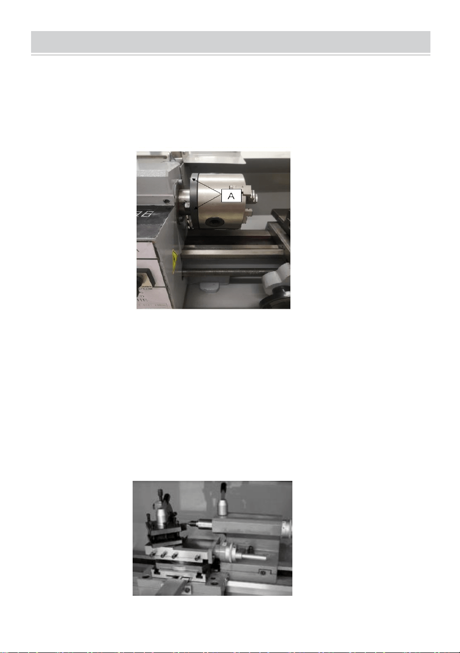
Replacement of Chuck
The head spindle holding fixture is cylindrical. Loose three set screws and
nuts (A, Fig. 13 only two are shown) on the lathe chuck flange to remove
the chuck. Position the new chuck and fix it using the same set screws
and nuts.
Fig. 13
TOOL SET UP
Clamp the turning tool into the tool holder.
The tool must be clamped firmly. When turning, the tool has a tendency to
bend under the cutting force generated during the chip formation.
For best results, tool overhang should be kept to a minimum of 3/8" or less.
The cutting angle is correct when the cutting edge is in line with the center
axis of the workpiece. The correct height of the tool can be achieved by
comparing the tool point with the point of the center mounted in the tail
stock. If necessary, use steel spacer shims under the tool to get the
required height. (Fig. 14)
Fig. 14
- 18 -
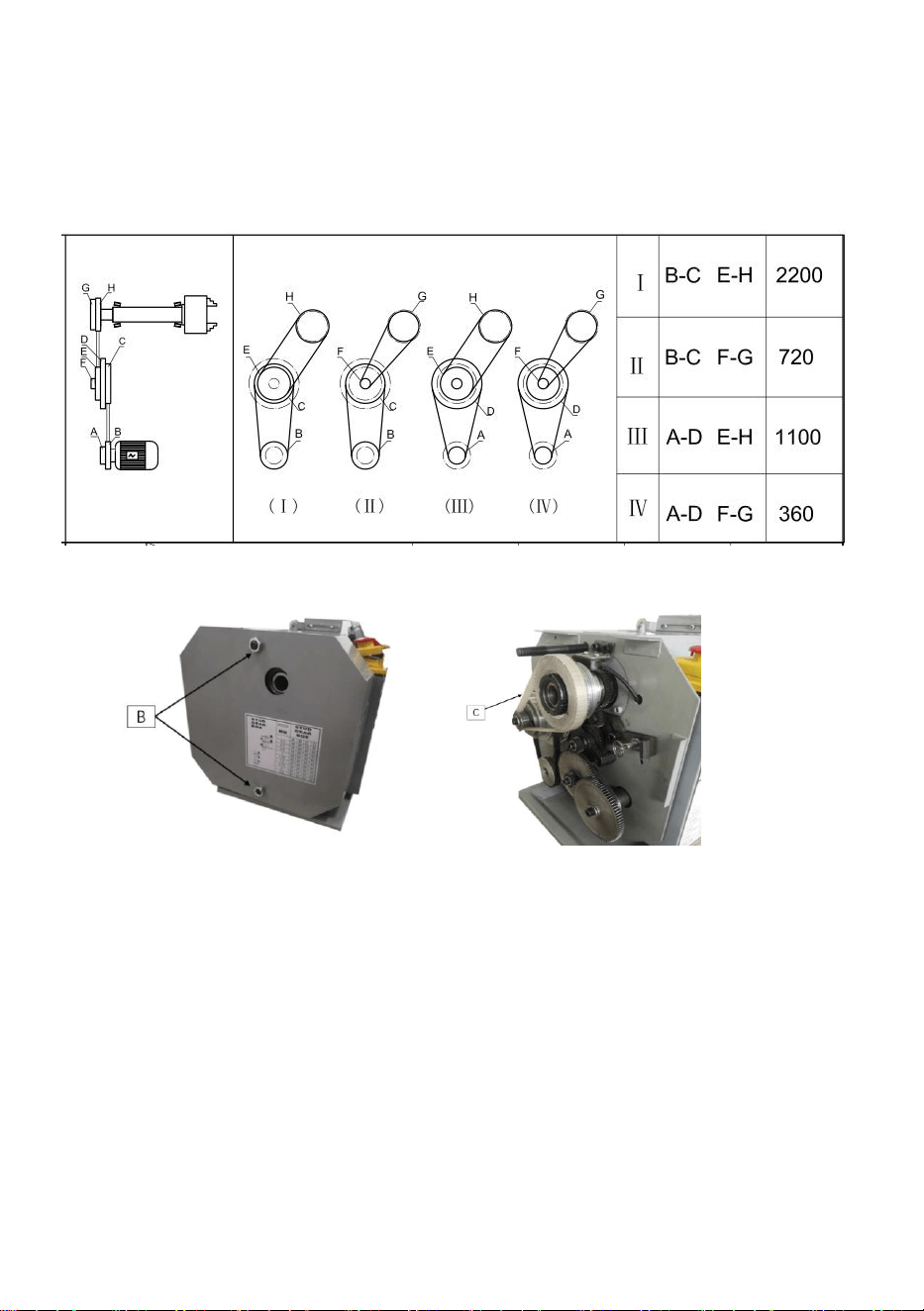
Change Speed
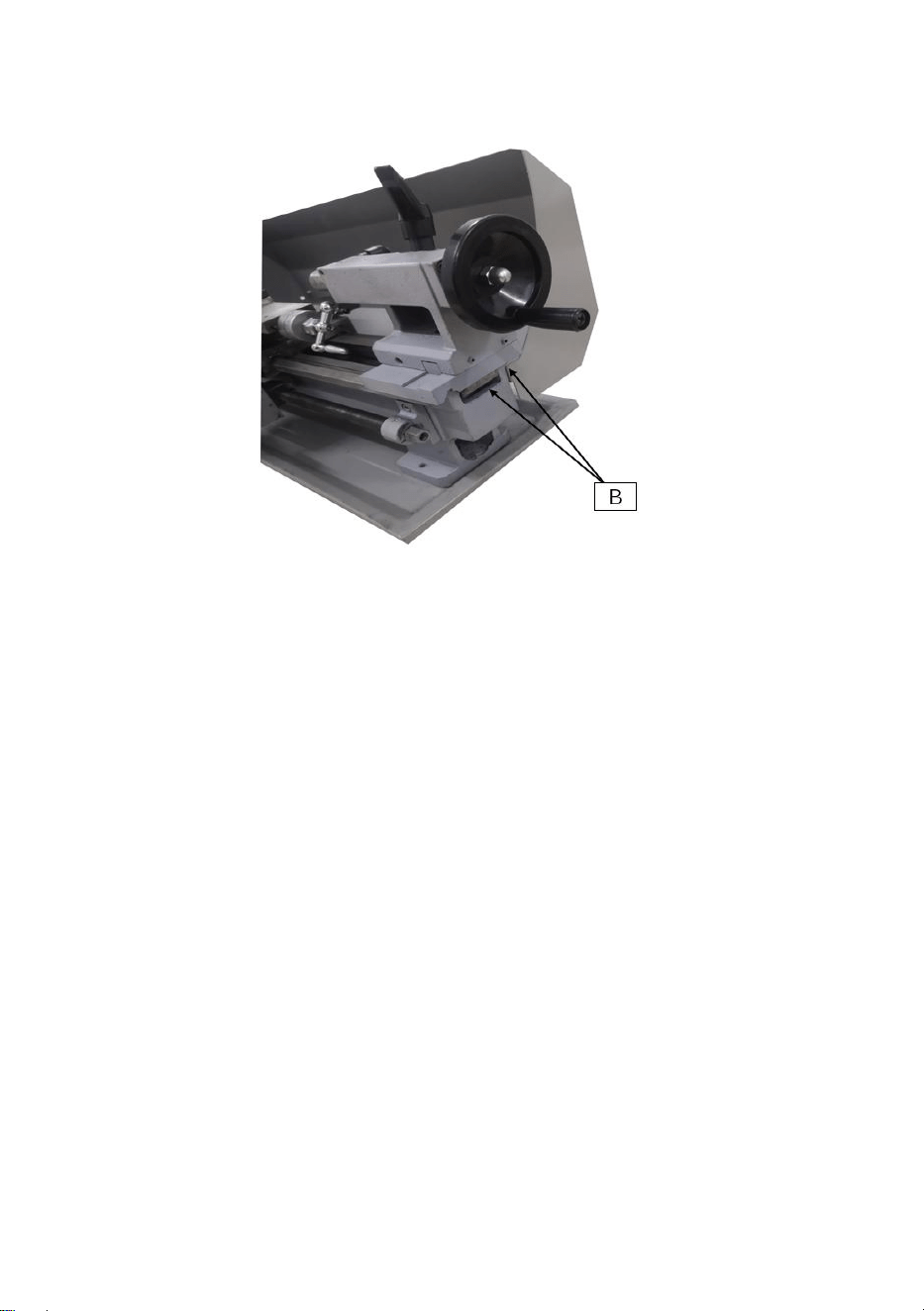
Unscrew the two fastening screws (B, Fig.15) and remove the protective
cover.
Adjust the V-belt(C,Fig.16)corresponding position.
Tighten the tension pulley and fasten the nut again.
Fig. 15 Fig. 16
- 19 -
Manual Turning
Apron travel, cross travel, and top slide hand wheel can be
operated for longitudinal or cross feeding. (Fig.17)
Fig. 17
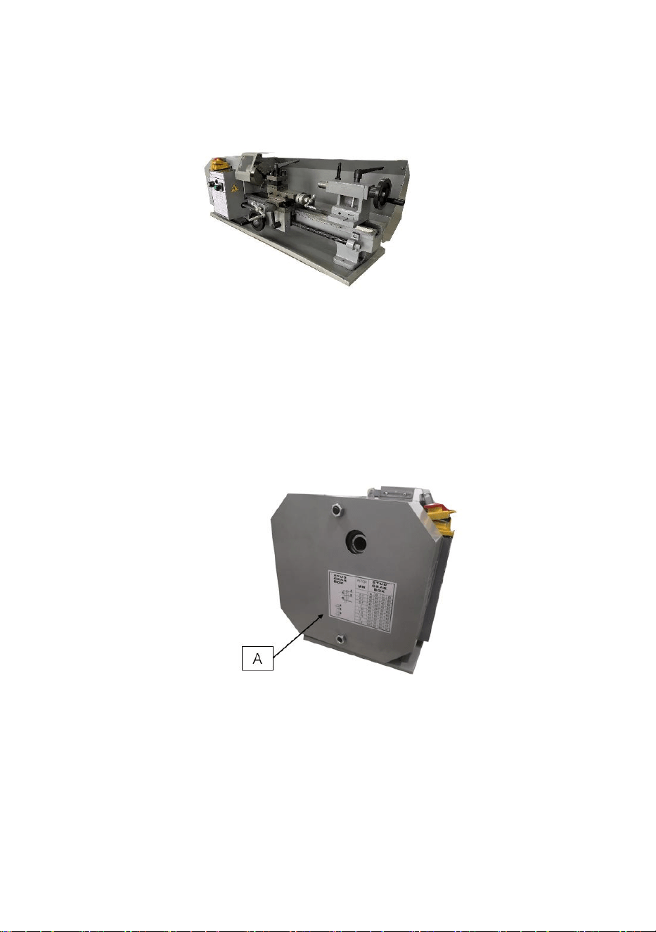
Longitudinal Turning with Auto.Feed
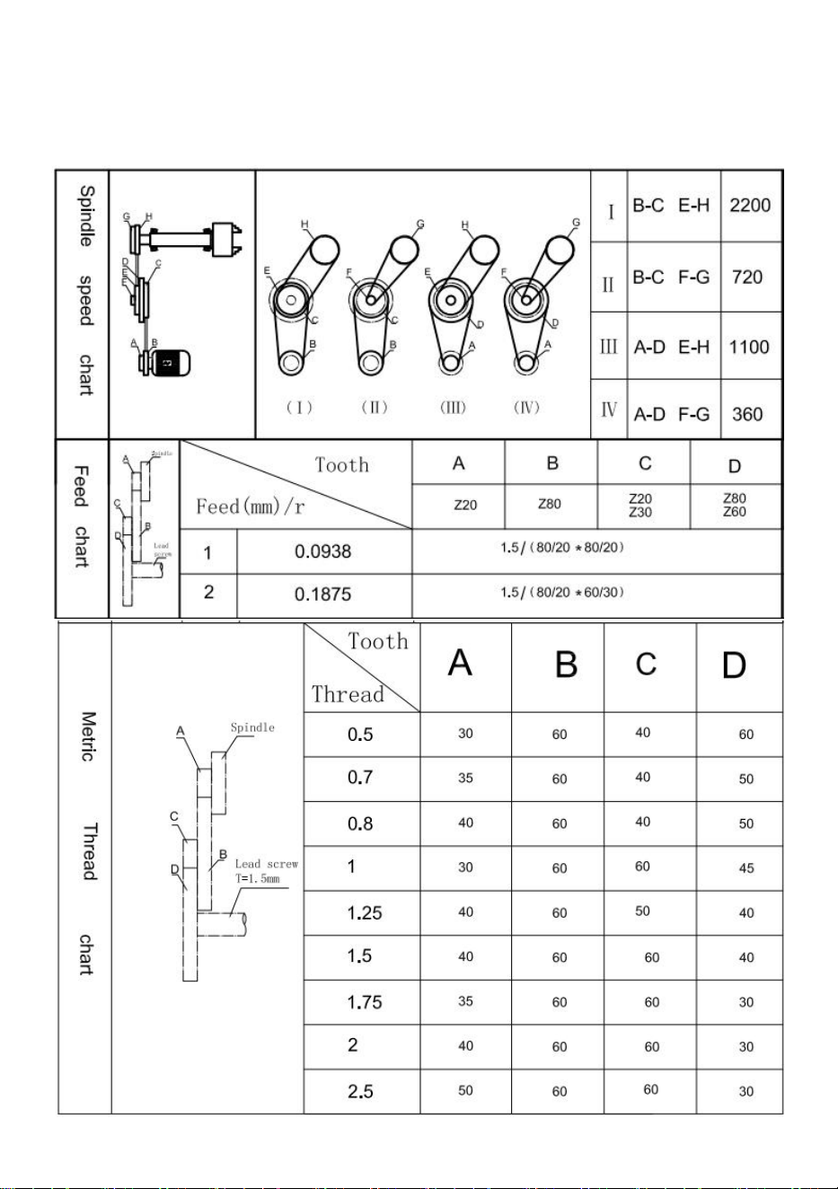
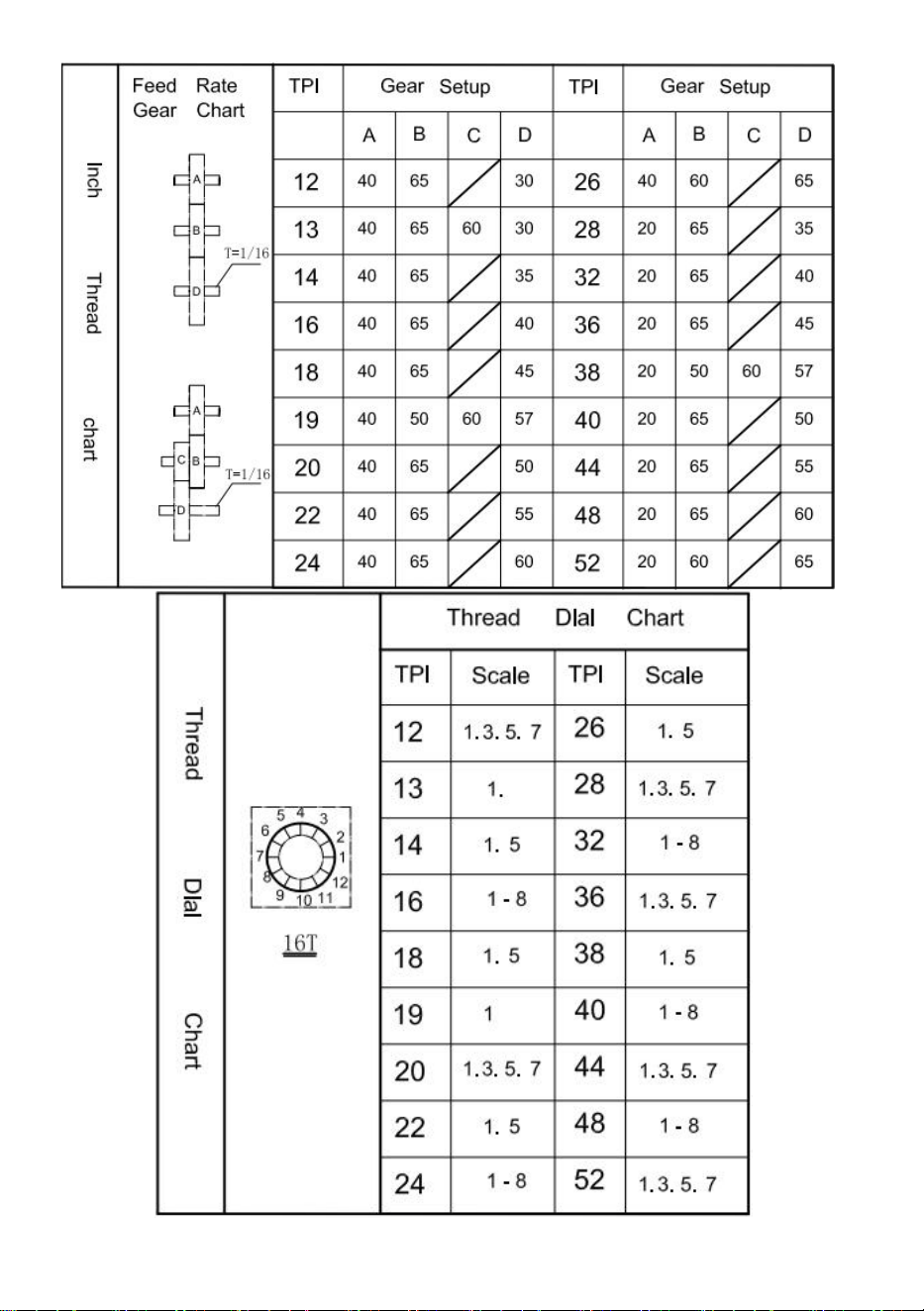
Use the table (A, Fig.18) on the lathe for selecting the feed speed or
the thread pitch. Adjust the change gear if the required feed or
thread pitch can not be obtained with the installed gear set.
Fig. 18
- 20 -
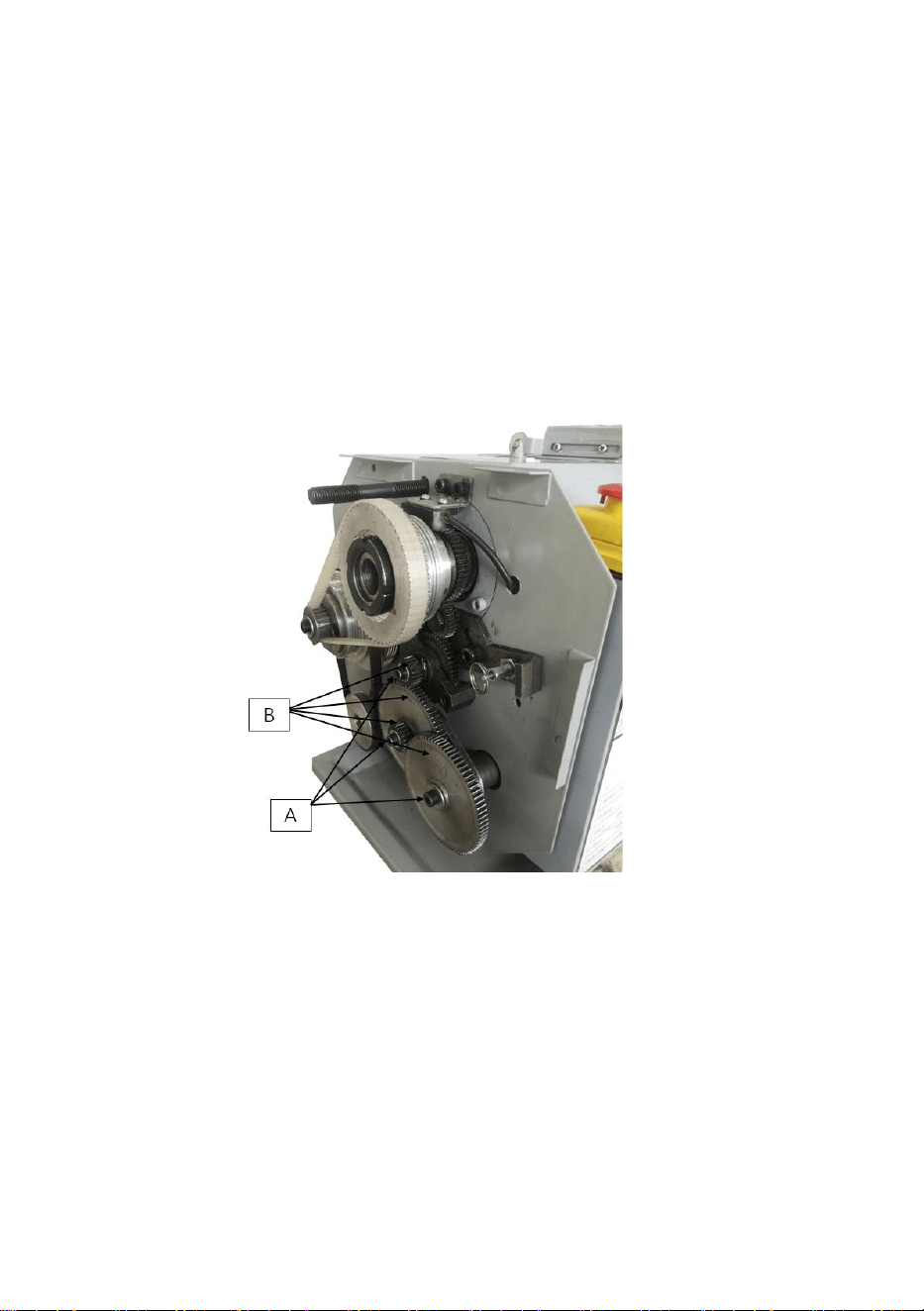
Change Gears Replacement
1. Disconnect the machine from the power source.
2. Unscrew the two fastening screws and remove the protective cover.
3. Unscrew the nut (A, Fig.19) in order to remove the change gears
from the front.
4. Install the gear couples (B,Fig.19) according to the thread and
feed chart (Fig.20) and screw the nut again.
5. Install the protective cover of the head stock and
reconnect the machine to the power supply.
Fig. 19
- 21 -
Pitch plate(Fig. 20)
THREADING AND FEEDING CHART
- 22 -
Fig. 20
- 23 -
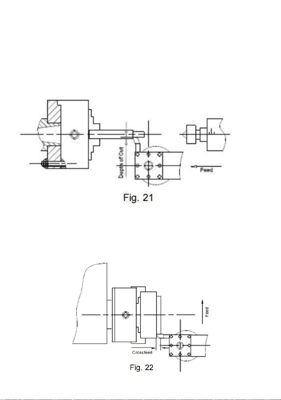
Cylindrical Turning (Fig. 21)
In the straight turning operation, the tool feeds parallel to the axis
of rotation of the workpiece. The feed can be either manual by
turning the hand wheel on the lathe saddle or the top slide, or by
activating the automatic feed. The cross feed for the depth of cut
is achieved using the cross slide.
End turning ( Fig. 22 )
In the facing operation, the tool feeds perpendicular to the axis of
rotation of the workpiece. The feed is made manually with the
cross slide hand wheel. The cross feed for cut depth is made with
the top slide or lathe saddle.

- 24 -
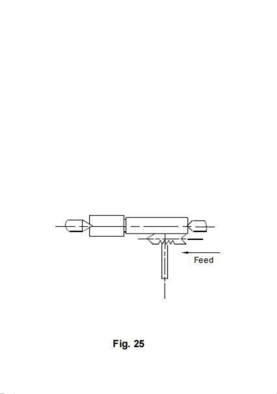
Turning: Slender shaft ( Fig. 23 )
For turning between centers, it is necessary to remove the chuck from the
spindle. Fit the M. T. 3 center into the spindle nose and the M.T. 2 center
into the tail stock. Mount the workpiece fitted with the driver dog between
the centers. The driver is driven by a catch or face plate.
Note: Always use a small amount of grease on the tail stock center to
prevent center tip from overheating.
Taper Turning Using Tail stock Off-Set
Adjust the deviation between the tailstock sleeve center and the spindle
center to complete the taper turning. The angle depends on the length of
the workpiece.
To off-set the tail stock, loosen locking screw (A, Fig.24).
Unscrew the set screw (B, Fig.24) on right end of the tailstock. Loosen the
front adjusting screw( C, Fig.24 ) and take up the same amount by
tightening the rear adjusting screw (D, Fig.24) until the desired taper has
been reached. The desired cross- adjustment can be read off the scale. (E,
Fig.24 ). First re-tighten the set screw (B, Fig,24) and then the two (front
and rear) adjusting screw to lock the tail stock in position. Re-tighten the
locking screw (A, Fig.24) of the tailstock. The workpiece must be held
between two centers and driven by a face plate and driver dog.
- 25 -
After taper turning, the tailstock should be returned to its original position
according to the zero position on the scale of tail stock. (E, Fig.24)
Thread Cutting
Set the machine up to the desired thread pitch (according to the
threading chart, Fig.20). Start the machine and engage the half nut.
When the tool reaches the part, it will cut the initial threading pass.
When the tool reaches the end of the cut, stop the machine by
turning the motor off and at the same time back the tool out of the
part so that it clears the thread. Do not disengage the half nut lever.
Reverse the motor direction to allow the cutting tool to traverse back
to the starting point. Repeat these steps until you have obtained the
desired results.
NOTES
Example: Male Thread
The workpiece diameter must have been turned to the diameter
of the desired thread.
The workpiece requires a chamfer at the beginning of the thread
and
Fig.24
- 26 -
an undercut at the thread runs out.
The speed must be as low as possible. The change gears
musthave been installed according to the required pitch.
The thread cutting tool must be exactly the sample shape
as the thread, must be absolutely rectangular and
clamped so that it coincides exactly with the turning enter.
The thread is produced in various cutting steps so that the
cutting tool has to be turned out of the thread completely (with
the cross slide) at the end of each cutting step.
The tool is withdrawn with the lead screw nut engaged by
inverting the change-over switch.
Stop the machine and feed the thread cutting tool in low cut
depths using the cross slide. Before each passage, place the
top slide approximately 0.2 to 0.3mm to the left and right
alternately in order to cut the thread free. This way, the thread
cutting tools cut only one thread flank with each passage. Keep
cutting the thread free until you have almost reached the full
depth of thread.
- 27 -
Lathe Accessories
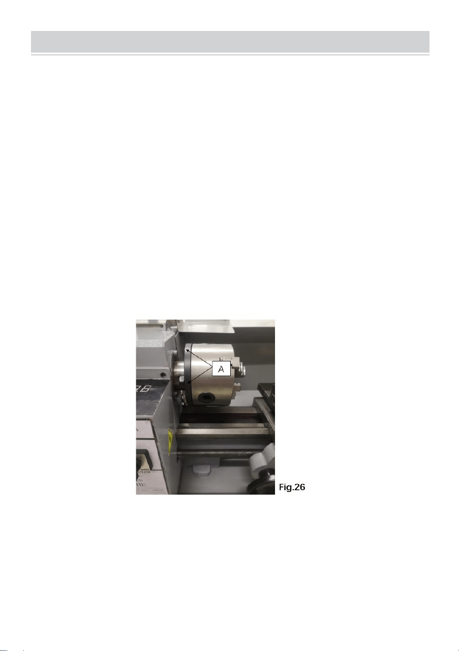
Three Jaw Universal Lathe Chuck
Using this universal chuck round triangular square hexagonal octagonal
and twelve,cornered stock may be clamped. (Fig.26)
Note: new lathes have very tight fitting jaws. This is necessary to ensure
accurate clamping and long service life- with repeated opening and
closing the jaw adjusts automatically and their operation becomes
progressively Smoother.
Note:
For the original 3, jaw chuck that was mounted on the lathe the factory
has mounted the chuck in the best way to guarantee the holding
accuracy with two "0" mark (A) Fig.26 showed on the chuck and chuck
flange.
There are two types of jaws: Internal and external jaws. Please note that
the number of jaws fits with the number inside the chuck's groove. Do not
mix them together. When you are going to mount them please mount them
in ascending order 0, 1 , 3 when you are going to take them out be sure to
- 28 -
take them out in descending order 3,1,0 one by one- After you finish this
procedure rotate the jaws to the smallest diameter and check that
the three jaws are well-fitted.
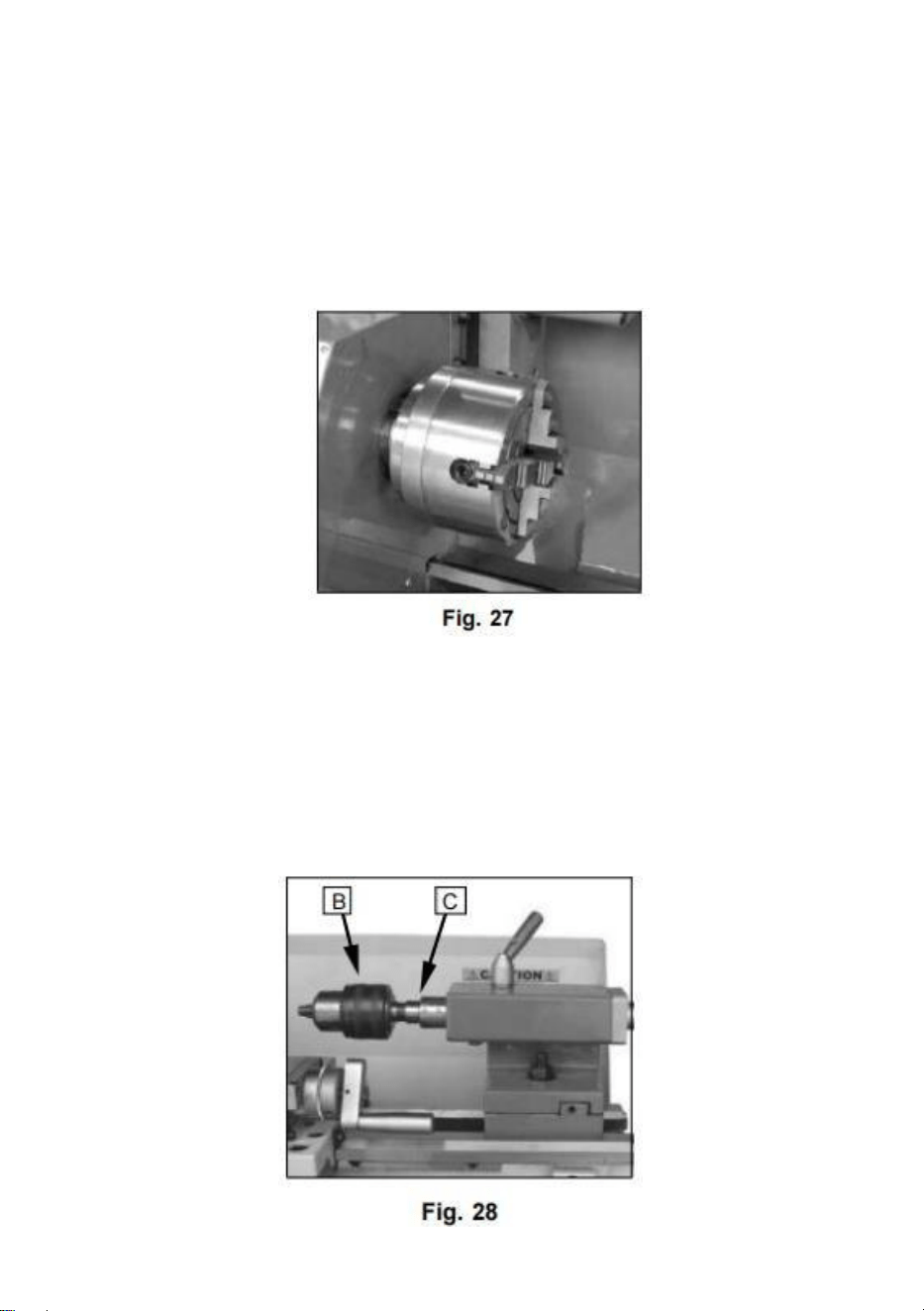
Four Jaw Independent Lathe Chuck
This special chuck has four independently adjustable chuck jaws- These
permit the holding of asymmetrical pieces and enable the accurate set,up
of cylindrical pieces. (Fig.27)
DriII Chuck ( optional)
Use the drill chuck to hold centering drills and twist drills in the tail stock-
(B) (Fig.28)
Morse Taper Arbor (optional)
An arbor is necessary for mounting the drill chuck in the tailstock. It has a
No. 1 Morse taper. (C) Fig.28
- 29 -
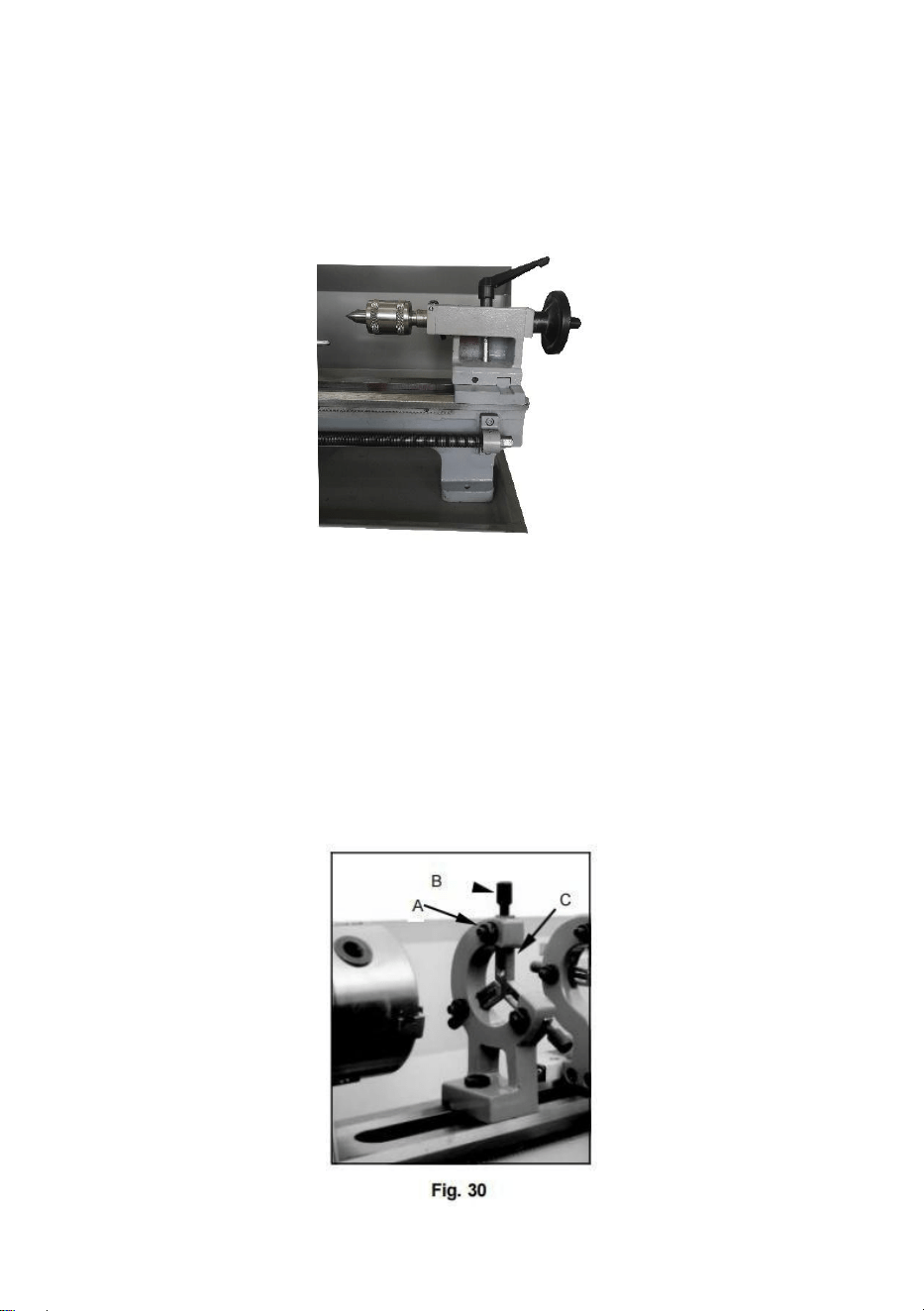
Live Center (optional)
The live center is mounted in ball bearings- Its use is highly recommended
for turning at speeds in excess of 6.RPM. ( Fig.29)
Steady Rest
The steady rest serves as a support for shafts on the free tail stock end.
For many operations the tail stock can not be used as it obstructs the
turning tool or drilling tool, and therefore, must be removed from the
machine. The
steady rest, which functions as an end support, ensures chatter- free
operation. The steady rest is mounted on the bed ways and is secured
from below with a locking plate. The grease requires continuous
lubrication at the contact points to prevent premature wear. (Fig.30)
Fig.29
- 30 -
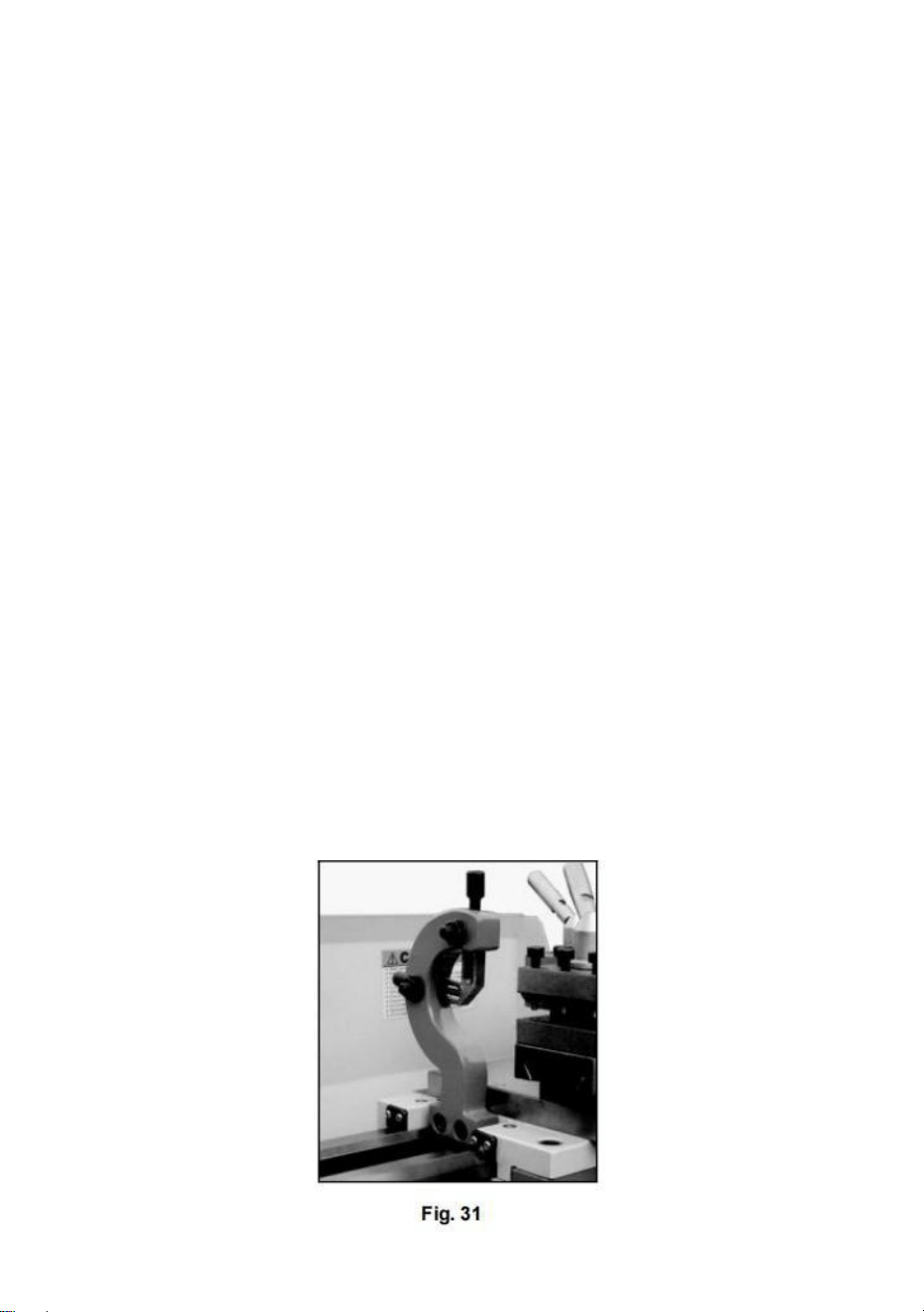
Setting the Steady Rest
1. Loosen three hex nuts. (A, Fig.31)
2. Loosen knurled screw (B, Fig.36) and open the sliding
fingers. (C, Fig.31) until the steady rest can be moved with its finger
around the workpiece. Secure the steady rest in position.
3 . Tighten knurled screws so that fingers are snug but not tight against
the workpiece. Tighten three nuts (A, Fig.31). Lubricate the sliding
points with machine oil.
4. When, after prolonged operation, the jaw show wear, the tips of
the fingers may be filed or re-milled.
Follow Rest
The following rest is mounted on the saddle and follows the
movement of the turning tool. Only two support blocks are required.
The place of the third support block is taken by the turning tool.
The following rest is used for turning operations on long, slender
workpieces. It prevents flexing of the workpiece under pressure
from the turning tool. ( Fig.31 )
Set the support blocks snug to the workpiece but not overly tight.
Lubricate the support blocks during operation to prevent premature
wear.
- 31 -
ADJUSTMENTS
After a period of time, wear in some of the moving components
may need to be adjusted.
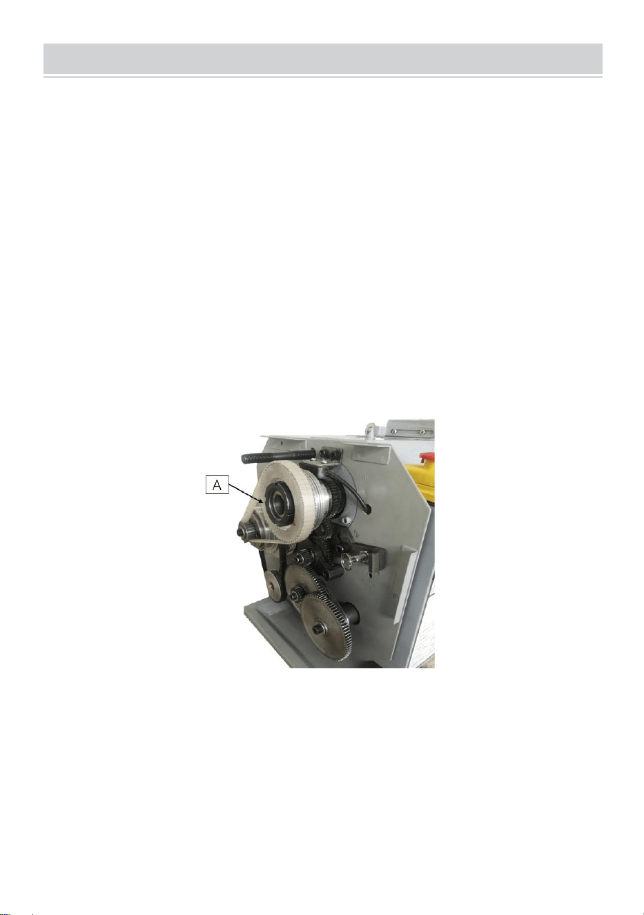
Main spindle Bearings
The main spindle bearings are adjusted at the factory. If end play
becomes evident after considerable use, the bearings may be
adjusted.
Fasten the slotted nut (A, Fig.32) on the back of the spindle, The
spindle should still revolve freely.
Caution: excessive tightening or preloading will damage the bearings.
Fig.32
- 32 -
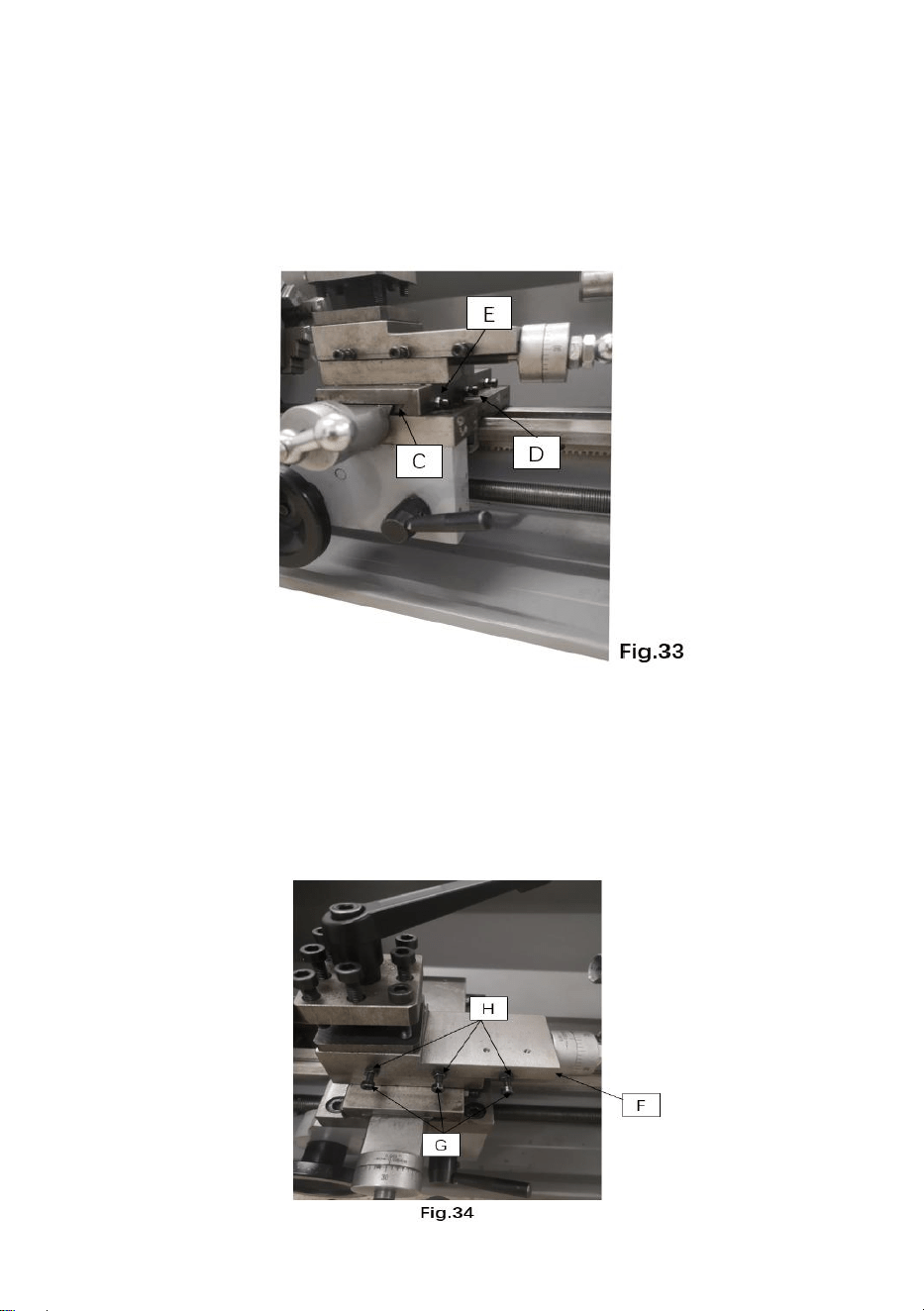
Adjustment of Cross slide
The cross slide is fitted with a gib strip(C, Fig.33) and can be
adjusted with screws (D, Fig.33) fitted with lock nuts. (E, Fig.33)
Loosen the lock nuts and tighten the set screws until slide moves
freely without play. Tighten lock nuts to retain adjustment.
Adjustment of Top slide
The top slide is fitted with a gib strip(F, Fig.34) and can be
adjusted with screws (G, Fig. 34) fitted with lock nuts. (H, Fig. 34)
Loosen the lock nuts and tighten the set screws until slide moves
freely without play. Tighten lock nuts to retain adjustment.
- 33 -
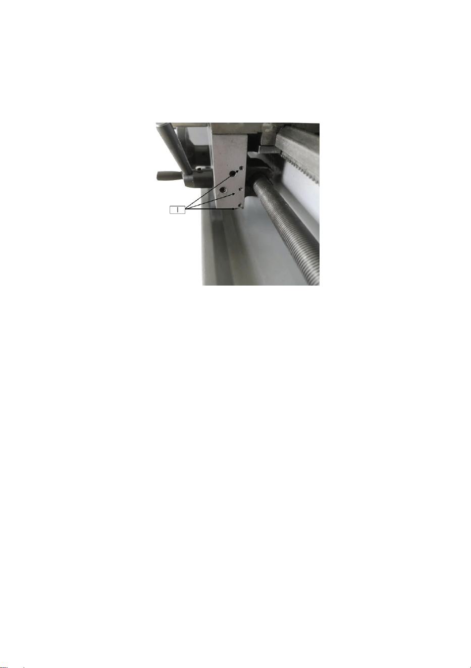
Adjustment of HaIf Nut Guide
The half nuts engagement can be adjusted with screws (I, Fig.35)
Loosen the screws on the right side of the apron and adjust the
control screws until both half nuts move freely without play. Tighten
the nut.
Fig.35
- 34 -
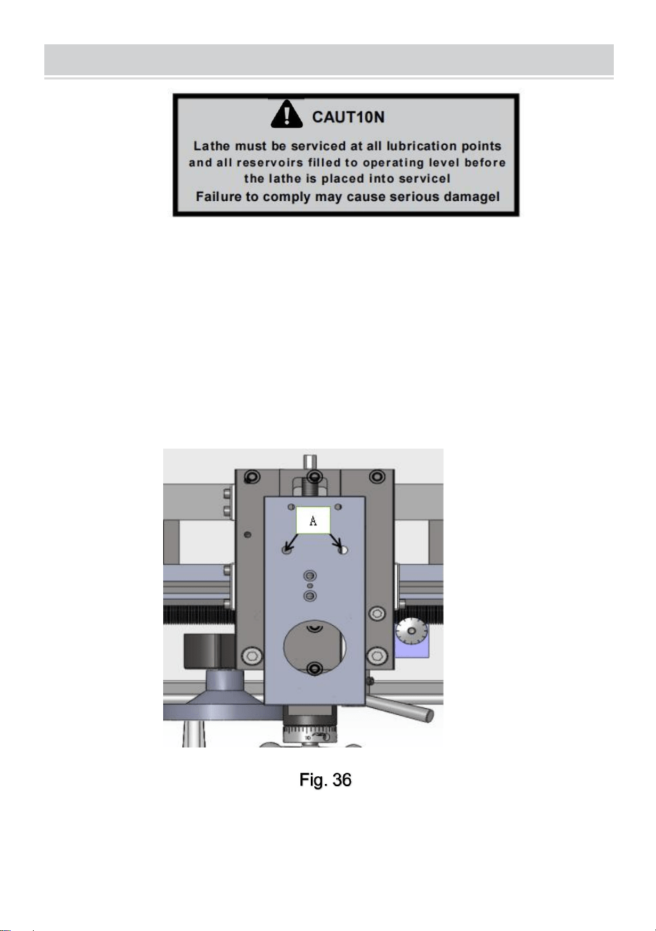
LUBRICATION
NOTES:
Lubricate all slideways lightly before every use.
Lubricate the change gears and the lead screw slightly
with grease.
1. Cross Slide
Lubricate two oil ports (A , Fig. 36 ) with 20W machine oil once daily.
- 35 -
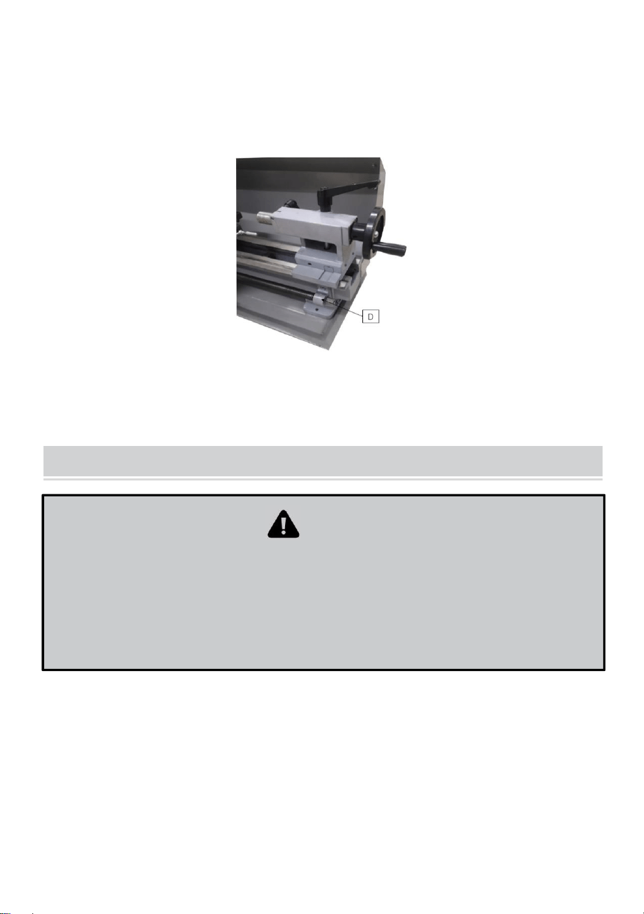
Electricity
WARNING!
Connection of the lathe and all other electrical work may only be carried
out by an authorized electrician!
Failure to comply may cause serious injury and damage to the machinery
and property!
2. Lead screw
Lubricate the right oil port (D, Fig.38) with 20W machine oil once
daily.
Fig. 38
The L2035 Lathe is rated at 650W, 1PH, 220V only. Confirm
power available at the lathe' s location is the same rating as the
lathe. Using the wiring diagram ( Fig. 39 ) for connecting the lathe
to the mains
supply. Make sure the lathe is properly grounded.
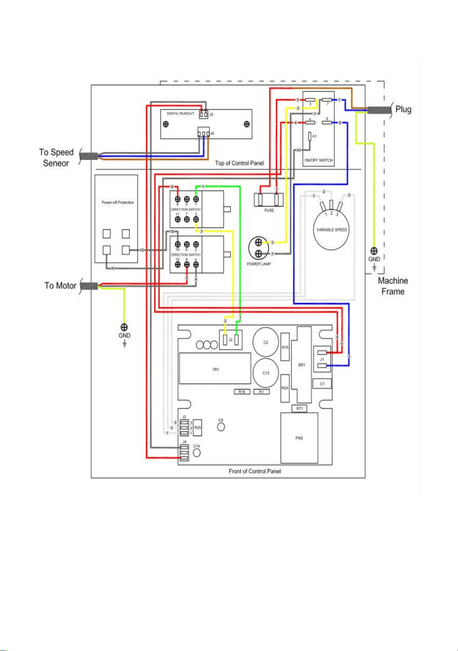
- 36 -
The following is wiring diagram of the lathe: (Fig.39)
Fig. 39

- 37 -
MAINTENANCE
Keep the maintenance of the machine tool during the operation to
guarantee the accuracy and service life of the machine tool.
1. In order to retain the machine's precision and functionality. it is essential
to treat it with care. Keep it clean and grease and lubricate it regularly.
Only through good care. You can be sure that the working quality of the
machine will remain constant.
NOTES: Disconnect the machine plug from the mains supply whenever
you carry out cleaning, maintenance or repair work!
Oil, grease and cleaning agents are pollutants and must not be disposed
of through the drains or in normal refuse. Dispose of those agents in
accordance with current legal requirements on the environment. Cleaning
rags impregnated with oil, grease and cleaning agents are easily
inflammable. Collect cleaning rags or cleaning wool in a suitable closed
vessel and dispose of them in an environmentally sound way - do not put
them with normal refuse!
1. Lubrication all slide ways lightly before every use. The change
gears and the lead screw must also be lightly lubricated with
grease.
2. During the operation. The chips which fall onto the sliding surface
should be cleaned timely. and the inspection should be often
made to prevent chips from falling into the position between the
machine tool saddle and lathe bed guide way. Asphalt felt should
be cleaned at certain time.
NOTES: Do not remove the chips with your bare hands. There is a risk of
cuts due to sharp edged chips. Never use flammable solvents or cleaning
agents or agents that generate noxious fumes!
Protect electrical components, such as motors, switches, switch boxes,
etc., against humidity when cleaning.
1. After the operation every day. Eliminate all the chips and clean
different parts of the machine tool and apply machine tool oil to
prevent rusting.

- 38 -
2. In order to maintain the machining accuracy. Take care of the
center. The surface of the machine tool for the chuck and the
guide way and avoid mechanical damage and the wear due to
improper guide.
3. If the damage is found. The maintenance should be done immediately.
NOTES: Repair work may only be carried out by qualified personnel with
the corresponding mechanical and electrical knowledge.

- 39 -
TROUBLE SHOOTING
Problem
Possible Reason
Elimination
Surface of workpiece
too rough
Tool blunt
Resharpen tool
Tool springs
Clamp tool
with less overhang
Feed too high
Reduce feed
Radius at the tool tip too small
Increase radius
workpiece becomes
coned
Centers are not aligned (tail stock has
offset)
Adjust tail stock to the center
Top slide not aligned well (cutting with
the top slide)
Align top slide well
Lathe is chattering
Feed too high
Reduce feed
Slack in main bearing
Adjust the main bearing
Center runs hot
workpiece has expanded
Loosen tail stock center
Tool has a short Life
Cutting speed too high
Reduce cutting speed
Cross feed too high
Lower cross
Feed (finishing allowance should
not exceed 0.5mm)
Insufficient cooling
More coolant
Flank wear too high
Clearance angle too small
Increase clearance angle
Tool tip not adjusted to center high
Correct height adjustment of
the tool
Cutting edge breaks
off
Wedge angle too small
(heat build up)
Increase wedge angle
Grinding crack due to wrong cooling
Cool uniformly
Excessive slack in the spindle bearing
Adjust the slack in the spindle
bearing
Arrangement (vibrations)
Arrangement
Cut thread is
wrong
Tool is clamped incorrectly
Adjust to the center
Cut thread is
Been started grinding the wrong way
Grind angle correctly
wrong
Wrong pitch
Adjust the right pitch
Wrong diameter
Turn the workpiece to
the correct diameter
Spindle does
not activate
Emergency stop switch activated
Unlock emergency stop
switch
- 40 -
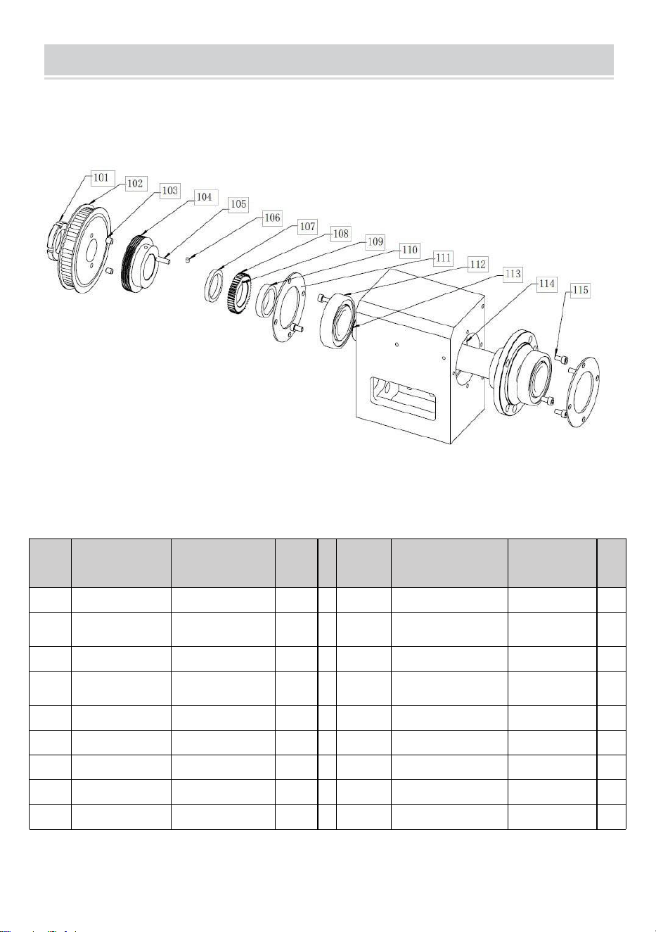
BREAKDOWN DIAGRAM AND PARTS LIST
Headstock Assembly
Parts
No.
Description
Specification
Qty
Parts
No.
Description
Specification
Qty
101
Spanner nut
M30 x 1.5
1
110
Spacer
1
102
Spindle timing
belt wheel
1
111
Bearing cover
2
103
Screw
M6x8
2
112
Ball bearing
1
104
Spindle multi
wedge pulley
1
113
Spindle
1
105
Key
C4 x4 x18
1
114
Headstock
1
106
Magnet
1
115
Screw
M5x10
6
107
Spacer
1
108
Gear
1
109
Key
C4 x4 x8
1
- 41 -
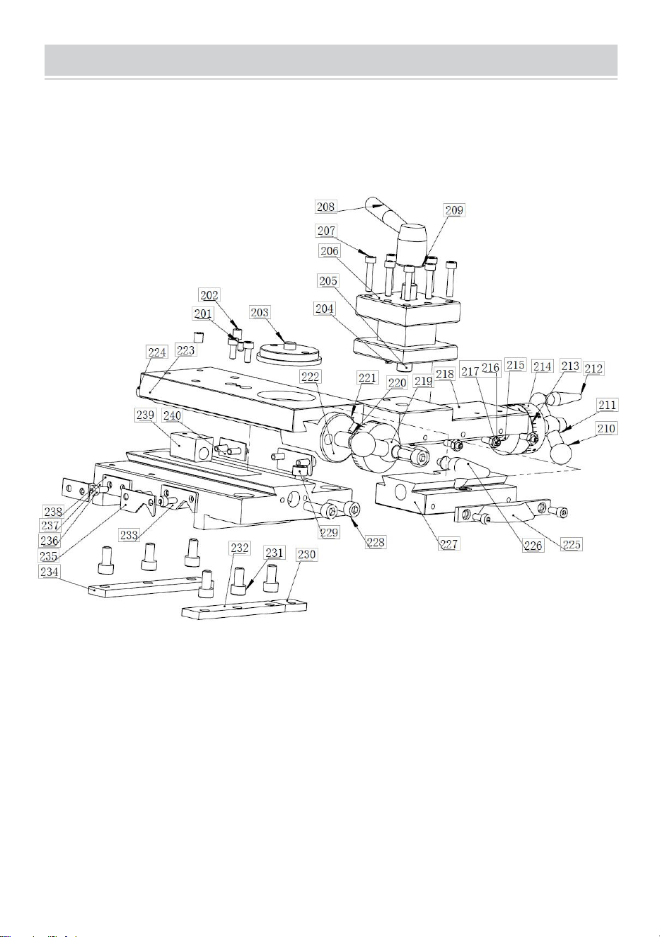
BREAKDOWN DIAGRAM AND PARTS LIST
Top slide, Cross slide, Carriage Assembly

- 42 -
Parts
No.
Description
Specification
Qty
Parts
No.
Description
Specification
Qty
201
Screw
M4x6
1
228
Screw
M6x20
2
202
Oil cup
2
229
Screw
M6x25
1
203
Swivel disk
1
230
Locking plate
1
204
Spring
1
231
Screw
M6x12
6
205
Stud bolt
1
232
Slide plate
1
206
Tool rest
1
233
Rubber wiper
2
207
Cap screw
M4x20
8
234
Slide plate
1
208
Lever
1
235
Wiper cover
2
209
Nut
1
236
Screw
M4x10
12
210
Three Ball
Handle
1
237
Saddle
1
211
Screw
M6x20
4
238
Rubber wiper
2
212
Lever
1
239
Feeding nut
1
213
Dial
1
240
Wiper cover
2
214
Dial
1
241
Gib
1
215
Lead Screw
1
242
1
216
Nut
M4
6
243
Screw
M4x16
2
217
Screw
M4x16
6
218
Top rest
1
219
Three Ball
Handle
1
220
Screw
M6x8
2
221
Gib
1
222
Bracket
1
223
Cross slide plate
1
224
Lead Screw
1
225
Angle block
1
226
Handle
1
227
Compound slide
base
1
- 43 -
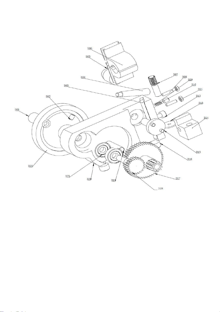
Apron Assembly

- 44 -
Parts
No.
Description
Specification
Qty
Parts
No.
Description
Specification
Qty
301
Hand wheel
lever
1
315
Groove cam
1
302
Screw
M6 x 8
3
316
Screw
M8 x20
2
303
Gib
1
317
Combo gear
1
304
Lever
1
318
Gear shaft
1
305
Handle base
1
319
Shaft
1
306
Half nut
1
320
Apron
1
307
Turbine shaft
1
321
Ball bearing
1
308
Screw
M4x16
2
322
Hand wheel
1
309
Steel ball
1
310
Spring
1
311
Nut
M4
2
312
Screw
M6x20
1
313
Dial
1
314
Thread dial seat
1
- 45 -
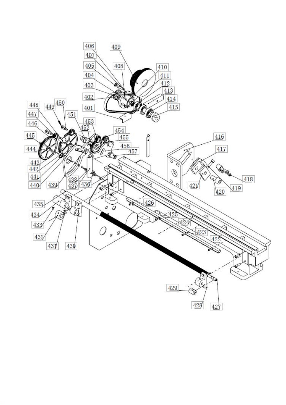
Bed,hanging wheel parts Assembly

- 46 -
Parts
No.
Description
Specification
Qty
Parts
No.
Description
Specification
Qty
401
Positioning plate
1
430
Leadscrew
bracket
1
402
Bridge Timing
belt wheel
1
431
Pin
1
403
Key
C5 x5 x10
1
432
Spacer
1
404
Belt
1
433
Oil cup
3
405
Washer
1
434
Leadscrew
bracket
1
406
Bolt
1
435
Leadscrew
1
407
Cap screw
M6 x20
1
436
Washer
1
408
Screw
M4 x10
6
437
Positioning plate
1
409
multi wedge
pulley
1
438
Stud bolt
1
410
Spring Washer
1
439
Mount
1
411
Spring Washer
1
440
Fixed cover
1
412
Ball bearing
6002
3
441
Shaft
1
413
Positioning plate
1
442
Spacer
1
414
Shaft
1
443
Knob plunger
1
415
Rocker arm
1
444
Key
B4 x 4x 8
2
416
Positioning plate
1
445
Screw
M6 x16
1
417
slider
1
446
Gear
2
418
fixed block
1
447
Gear
Z20
2
419
Screw
M6 x40
1
448
Key sleeve
1
420
Screw
M12 x25
1
449
Washer
2
421
Slider gasket
1
450
Screw
M5 x10
2
422
Screw
M5 x16
8
451
Bolt
1
423
Rack
1
452
Gear
Z45
1
424
Bed way
1
453
Gear
Z20
1
425
Screw
M3 x12
4
454
Gear
Z25
1
426
Bottom plate
1
455
Gear bolt
1
427
Screw
M8 x12
1
456
Nut
M8
1
428
Leadscrew
bracket
1
457
Intermediate
wheel sleeve
1
429
Locking nut
1
- 47 -
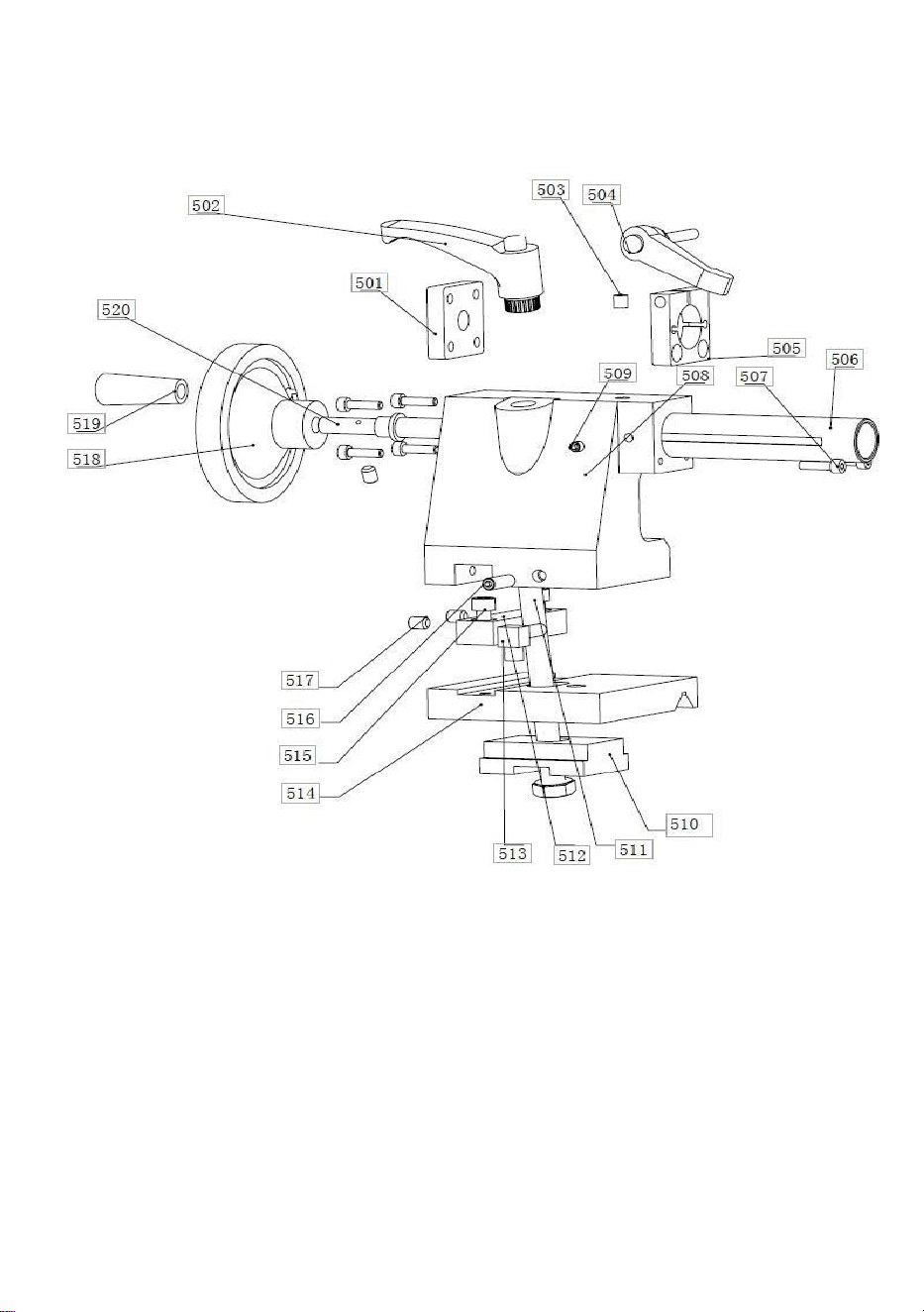
Tail stock Assembly

- 48 -
Parts
No.
Description
Specification
Qty
Parts
No.
Description
Specification
Qty
501
Tailstock rear
cover
1
515
Cap Screw
M6 x20
2
502
Handle
1
516
Screw
M6 x20
2
503
Oil cup
1
517
Screw
M6 x20
1
504
Tightening
handle
1
518
Hand wheel
1
505
Bracket
1
519
Hand lever
1
506
Quill
1
520
Leadscrew
1
507
Cap screw
M4 x16
6
508
Tailstock
1
509
Screw
M5x5
1
510
Tailstock
suspension
block
1
511
Bolt
1
512
Tailstock Key
1
513
Limit Pin
1
514
Base plate
1
- 49 -
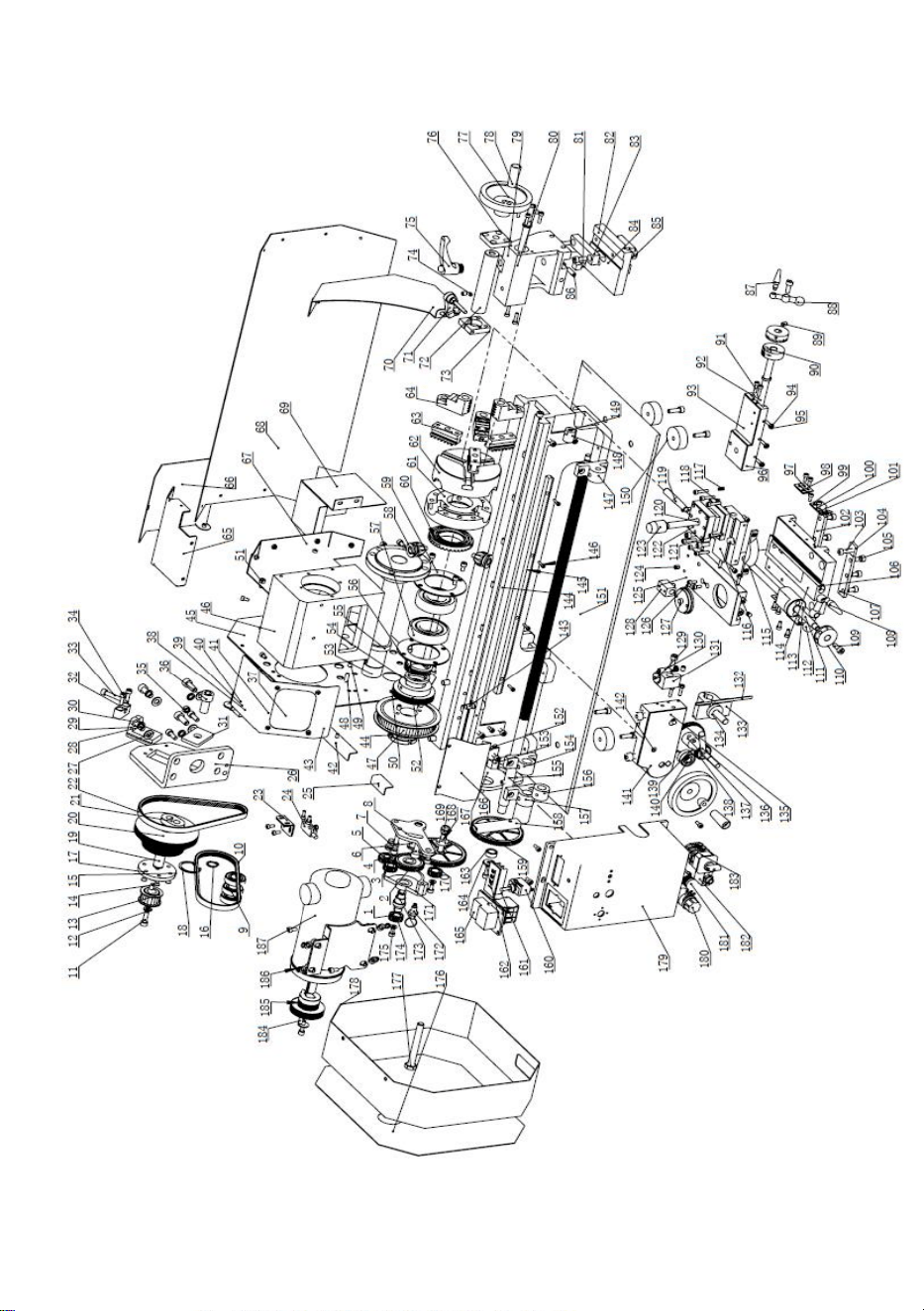
General Assembly

- 50 -
Parts
No.
Description
Specification
Qty
Parts
No.
Description
Specificatio
n
Qty
1
Key
B4x4 x8
2
101
Rubber matting
2
2
Gear
Z45
1
102
Saddle press
plate
1
3
Gear
Z20
1
103
Screw
M6 x25
1
4
Screw
M8 x20
1
104
Saddle locking plate
1
5
Gear
Z25
1
105
Screw
M6 x12
11
6
Sleeve
1
106
Gib
1
7
Gear Bolt
2
107
Saddle press
plate
1
8
Nut
M8
1
108
Handle lever
1
9
Ball Bearing
3
109
Screw
1
10
Belt
1
110
Dial scale
1
11
Screw
M6 x20
11
111
Lead screw
1
12
Washer
6
112
Three ball handle
1
13
Bridge Timing
belt wheel
1
113
Bracket
1
14
Key
C5 x5 x10
1
114
Saddle
1
15
Bolt
1
115
Dial scale
1
16
Spring Washer
1
116
Compound rest
1
17
Screw
M4 x10
6
117
Spring
1
18
Spring Washer
1
118
Pin
1
19
Bolt
1
119
Tool rest lever
1
20
multi wedge
pulley
1
120
Stud bolt
1
21
Swinging arm
1
121
Screw
M4 x20
8
22
Belt
1
122
Tool post
1
23
Mounting plate
1
123
Tool post nut
1
24
Speed
measuring head
1
124
Oil cup
6
25
Positioning plate
4
125
Cross slide
1
26
Positioning plate
1
126
Screw
M4 x 6
1
27
Washer
4
127
Swivel disk
1
28
Screw
M8 x20
9
128
Feeding nut
1
29
Slider
1
129
Dial scale
1

- 51 -
30
Spring Washer
4
130
Gear bolt
1
31
Slider Gasket
1
131
Seat
1
32
Fixed Block
1
132
Gib
1
33
Screw
M6x40
1
133
Half nut
1
34
Screw
M5 x16
8
134
Shift fork
1
35
Nut
M6
1
135
Steel ball
1
36
Screw
M12x25
1
136
Lever
1
37
Chuck Cover
Window
1
137
Seat
1
38
c
138
Gear bolt
1
39
Screw
M4x20
2
139
Combo gear
1
40
Shifting Fork
1
140
Ball bearing
1
41
Travel Switch
1
141
Apron
1
42
Positioning plate
1
142
Shaft
1
43
Chuck Cover
1
143
Screw
M8 x 10 x10
1
44
Spanner Nut
M30 x1.5
1
144
Bed way
1
45
Support Plate
1
145
Rack
1
46
Head stock
1
146
Screw
M3x12
4
47
Spindle
synchronous belt
wheel
1
147
Lead screw
bracket
1
48
Key
C4 x4 x18
1
148
Nut
1
49
Key
C4 x4 x8
1
149
Screw
M8x12
1
50
Test block
1
150
Rubber foot
4
51
Screw
M5x10
18
151
Chip tray
1
52
Pulley
1
152
Pin
1
53
Spindle
1
153
Stud
1
54
Spacer
1
154
Lead screw
bracket
1
55
Spacer
1
155
Lead screw
1
56
Gear
1
156
Sleeve
1
57
Ball bearing
2
157
Bracket
1
58
Bevel gear
2
158
Position plate
2
59
Bearing cover
2
159
Gear
2
60
Bevel gear
1
160
Switch
1
61
Chuck bottom
1
161
Digital panel
1

- 52 -
62
Chuck head
1
162
Screw
M6x16
1
63
Chuck jaw
3
163
Spacer
1
64
Chuck jaw
3
164
Washer
2
65
Switch mounting
block
1
165
On/off button
1
66
Motor cover
1
166
Bearing cover
1
67
Splash plate
1
167
Bracket board
1
68
Splash plate
1
168
Shaft
1
69
Motor cover
1
169
Nut
1
70
Splash plate
1
170
Sleeve
1
71
Adjustable
locking handle
1
171
Mount
1
72
Quill
1
172
Knob plunger
1
73
Locking cover
1
173
Bolt
1
74
Screw
M5x5
1
174
Gear
Z20
2
75
Hand lever
1
175
Washer
2
76
Tailstock cover
1
176
Transmission box
1
77
Hand wheel
1
177
Bolt
M10 x 80
1
78
Hand wheel
lever
1
178
Transmission box
cover
1
79
Tail stock
1
179
Control box
1
80
Lead screw
1
180
Speed knob
1
81
Pin
1
181
Indicator light
1
82
Tail stock
baseboard
1
182
Overload
protector
1
83
Key
1
183
Changeover
switch
1
84
Hanging block
1
184
Key
C5 x 5 x20
1
85
Bolt
1
185
Pulley
1
86
Screw
M6x20
2
186
Spring washer
1
87
Handle lever
1
187
Motor
1
88
Three ball
handle
1
89
Screw
M6x8
11
90
Dial scale
1
91
Screw
M4x16
8
92
Lead screw
1

- 53 -
93
Compound rest
1
94
Screw
M4x16
8
95
Nut
M4
24
96
Gib
1
97
Press plate
2
98
Rubber matting
2
99
Press plate
2
100
Screw
M4x10
20
MADE IN CHINA