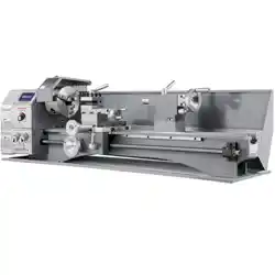
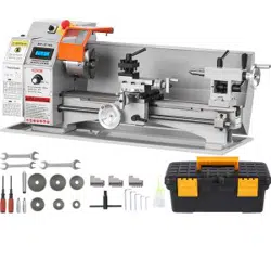
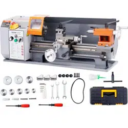
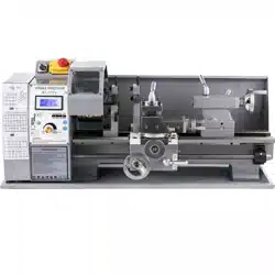
OPERATOR'S MANUAL MX - 600A
NOTE
The information contained in this handbook is intended as a guide to the operation of these machines and does not form part of any contract. The data it contains has been obtained from the machine manufacturer and from other sources. Whilst every effort has been made to ensure the accuracy of these transcriptions it would be impracticable to verify each and every item. Furthermore, development of the machine may mean that the equipment supplied may differ in detail from the descriptions herein. The responsibility therefore lies with the user to satisfy himself that the equipment or process described is suitable for the purpose intended.
LIMITED WARRANTY
We Makes every effort to assure that its products meet high quality and durability standards and warrants to the original retail consumer/purchaser of our products that each product be free from defects in materials and workmanship as follow: ONE YEAR LIMITED WARRANTY ON ALL PRODUCTS UNLESSSPECIFIED OTHERWISE. This Warranty does not apply to defects due directly or indirectly to misuse, abuse, negligence or accidents, normal wear-and-tear, repair or alterations outside our facilities, or to a lack of maintenance.
We shall in no event be liable for death, injuries to persons or property or for incidental, contingent, special, or consequential damages arising from the use of our products.
To take advantage of this warranty, the product or part must be returned to us for examination, postage prepaid. Proof of purchase date and an explanation of the complaint must accompany the merc handle. If our inspection discloses a defect, we will either repair or replace the product, or refund the purchases price if we cannot readily and quickly provide a repair or replacement, if you are willing to accept a refund. We will return repaired product or replacement at our expense, but if it is determined there in no defect, or that the defect resulted from causes not within the scope of Herman's warranty, then the user must bear the cost of storing and returning the product.
The manufacturers reserve the right to change specifications at any time as they continually strive to achieve better quality equipment.
SAFETY INSTRUCTIONS
- This machine is designed and intended for use by properly trained and experienced personnel only. If you are not familiar with the proper safe use of lathes, do not use this machine until proper training and knowledge has been obtained.
- Keep guards in place. Safety guards must be kept in place and in working order.
- Remove adjusting keys and wrenches. Before turning on machine, check to see that any adjusting wrenches are removed from the tool.
- Reduce the risk of unintentional starting. Make sure switch is in the OFF position before plugging in the tool.
- Do not force tool. Always use a tool at the rate for which it was designed.
- Use the right tool. Do not force a tool or attachment to do a job for which it was not designed.
- Maintain tools with care. Keep tools sharp and clean for best and safest performance. Follow instructions for lubrication and changing accessories.
- Always disconnect the machine from the power source before adjusting or servicing.
- Check for damaged parts. Check for alignment of moving parts, breakage of parts, mounting, and any other condition that may affect the tools operation. A guard or any part that is damaged should be repaired or replaced.
- Turn power off. Never leave a machine unattended. Do not leave a machine until it comes to a complete stop.
- Keep work area clean, Cluttered areas and bench invite accidents.
- Do not use in a dangerous environment. Do not use power tools in damp or wet locations, or expose them to rain. Keep work area well lighted.
- Keep children and visitors away. All visitors should be kept a safe distance from the work area.
- Make the workshop child proof. Use padlocks, master switches, and remove starter keys.
- Wear proper apparel. Loose clothing, gloves, neckties, rings, bracelets, or other jewelry may get caught in moving parts. Non-slip footwear is recommended. Wear protective hair covering to contain long hair. Do not wear any type of glove.
- Always use safety glasses. Every day glasses only have impact resistant lenses; they are not safety glasses.
- Do not overreach. Keep proper footing and balance at all times.
- Do not put hands near the cutter while the machine is operating.
- Do not perform any set-up work while machine is operating.
- Read and understand all warnings posted on the machine.
- This manual is intended to familiarize you with the technical aspects of this lathe. It is not, nor was it intended to be a training manual.
- Failure to comply with all of these warnings may result in serious injury.
- Some dust created by power sanding, sawing, grinding, drilling and other construction activities contains chemicals known to cause cancer, birth defects or other reproductive harm. Some examples of these chemicals are lead from lead based paint; crystalline silica from bricks and cement and other masonry products.
- Your risk from those exposures varies, depending on how often you do this type of work. To reduce your exposure to these chemicals: work in a well ventilated area, and work with approved safety equipment, such as those dust masks that are specifically designed to filter our microscopic particles.
SPECIFICATIONS
| MX600A |
| Capacities: |
| Swing Over Bed |
220mm |
| Swing Over Cross Slide |
600mm |
| Distance Between Centers |
600mm |
| Width of Bed |
100mm |
| Headstock: |
| Hole Through Spindle |
38mm |
| Taper in Spindle Nose |
Mt5 |
| Number of Spindle Speeds |
Variable |
| Range of Spindle Speeds |
0-2500RPM |
| Feeding and Threading: |
| Number of Metric Threads |
10 |
| Range of Metric Threads |
0.5~3mm |
| Number of Imperial Threads |
8 |
| Range of Imperial Threads |
8~44 T.P.I. |
| Range of Longitudinal Feed |
0.1~0.20mm |
| Compound and Carriage: |
| Tool Post Type |
4-Way |
| Maximum Compound Slide Travel |
55mm |
| Maximum Cross Slide Travel |
75mm |
| Maximum Carriage Travel |
276mm |
| Tailstock: |
| Tailstock Spindle Travel |
60mm |
| Taper in Tailstock Spindle |
MT2 |
| Miscellaneous: |
1.1KW |
| Main Motor |
230V 120V |
| Dimension: |
| Length: |
1200mm |
| Width: |
390mm |
| Height: |
370mm |
| Weight: |
MX600A 72KGS/83KGS |
The specifications in this manual are given as general information and are not binding. We reserves the right to effect, at any time and without prior notice, changes or alterations to parts, fitting and accessory equipment deemed necessary for any reason whatsoever.
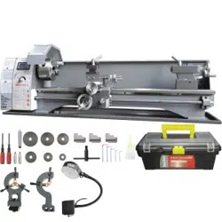
TOOLBOX CONTENTS
1 Dead Center MT2
1 Oil Gun
1 Cross Screwdriver
1 Flat Screwdriver
5 Hex Socket Wrench 3.4.5.6.8mm
3 Double End Head Wrench 8-10mm, 12-14mm, 13-16mm
6 Change Gears 30T, 40T, 50T, 52T, 60T, 66T
The key for 4-jaw chunk the center rack and the follow tool carrier are selected parts
UNCRATING AND CLEAN-UP
- Finish removing the wooden crate from around the lathe
- Check all the accessories of the machine tool according to the packing list.
- Unbolt the lathe from the shipping crate bottom.
- Choose a location for the lathe that is dray, has good lighting and has enough room to be able to service the lathe on all four sides.
- With adequate lifting equipment, slowly raise the lathe off the shipping crate bottom. Do not lift by spindle. Make sure lathe is balanced before moving to sturdy bench or stand.
- To avoid twisting the bed, the lathe's location must be absolutely flat and level. Bolt the lathe to the stand (if used). If using a bench, through bolt for best performance.
- Clean all rust protected surfaces using a mild commercial solvent, kerosene or diesel fuel. Do not use paint thinner, gasoline or lacquer thinner. These will damage painted surfaces. Cover all cleaned surfaces with a light film of 20W machine oil.
- Remove the end gear cover. Clean all components of the end gear assembly and coat all gears with heavy, non-slinging grease.
GENERAL DESCRIPTION
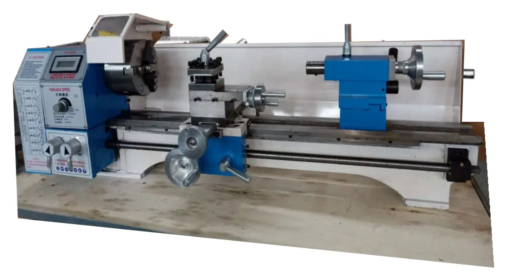
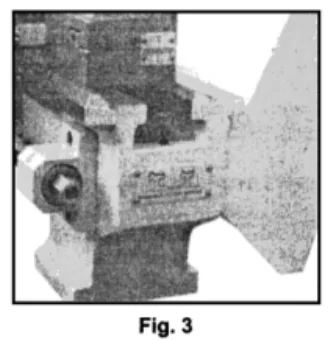
Lathe Bed (Fig. 3)
The lathe bed is made of high-grade iron. By combining high cheeks with strong cross ribs, a bed of low vibration and rigidity is produced. It integrates the headstock and drive unit, for attaching the carriage and leadscrew. The two precision-ground V - sideways, re-enforced by heat hardening and grinding, are the accurate guide for the carriage and tailstock. The main motor is mounted to the rear of the left side of the bed.
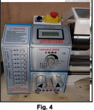
Headstock (Fig. 4)
The headstock is cast from high grade, low vibration cast iron. It is bolted to the bed with four screws. The headstock houses the main spindle with two precision taper roller bearings and the drive unit. The main spindle transmits the torque during the turning process. It also holds the workpieces and clamping devices. (e.g. 3-jaw chuck).
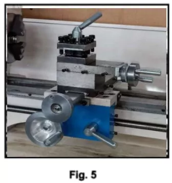
Carriage (Fig. 5)
The carriage is made from high quality cast iron. The slide parts are smoothly ground. They fit the V on the bed without play. The lower sliding parts can be easily and simply adjusted. The cross slide is mounted on the carriage and moves on a dove tailed slide. Play in the cross slide may be adjusted with the gibs.
Move the cross slide with its conveniently positioned handwheel. There is a graduated collar on the handwheel.
A four way tool post is fitted on the top slide and allows four tools to be clamped. Loosen the center clamp handle to rotate any of the four tools into position.
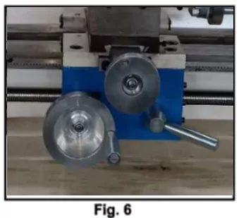
Apron (Fig. 6)
The apron is mounted on the bed. It houses the half nut with an engaging lever for activating the automatic feed. The half nut gibs can be adjusted from the outside.
A rack, mounted on the bed, and a pinion operated by handwheel on the carriage allow for quick travel of the apron.
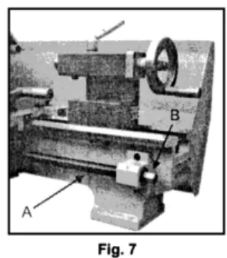
Leadscrew
The leadscrew (A, Fig.7) is mounted on the front of the machine bed. It is connected to the gear box at the left for automatic feed and is supported by bearing on both ends. The hex nut (B, Fig.7) on the right end is designed to take up play on the leadscrew.
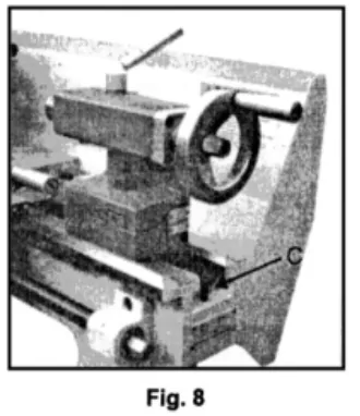
Tailstock (Fig.8)
The tailstock slides on a V way and can be clamped at any location. The tailstock has a heavy-duty spindle with a Morse taper No. 2 socket and a graduated scale. The spindle can be clamped at any location with a clamping lever. The spindle is moved with a handwheel at the end of the tailstock.
NOTE: Fit the securing screw (C, Fig. 8) at the end of the lathe in order to prevent the tailstock from falling off the lathe bed.
CONTROLS
1. Emergency Button ON/OFF Switch (D, Fig. 9)
The machine is switched on and off with ON/OFF button. Depress to stop all machine functions. To restart, lift the cover and press ON button.
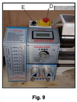
2. Change-over Switch (E, Fig. 9)
After the machine is switched on, turn the switch to "F" position for counter-clockwise spindle rotation (forward). Turn the switch to "R" position for clockwise spindle rotation (reverse). "0" position is OFF and the spindle remains idle.
3. Variable Speed Control Switch (F, Fig. 9)
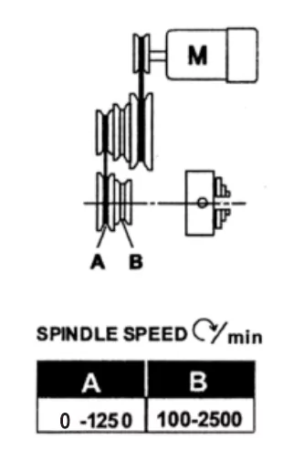
Turn the switch clockwise to increase the spindle speed. Turn the switch counter-clockwise to decrease the spindle speed. The possible speed range is dependent from the position of the drive belt.
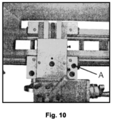
4. Carriage Lock
Turn hex socket cap screw (A, Fig.10) clockwise and tighten to lock. Turn counter-clockwise and loosen to unlock. Caution: carriage lock screw must be unlocked before engaging automatic feeds or damage to lathe may occur.
5. Longitudinal Traverse Handwheel (B, Fig. 11)
Rotate hand wheel clockwise to move the apron assembly toward the tailstock (right). Rotate the hand wheel counter-clockwise to move the apron assembly toward the headstock (left).
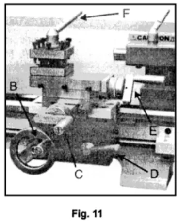
6. Cross Traverse Lever (C, Fig. 11)
Clockwise rotation moves the cross slide toward the rear of the machine.
7. Half Nut Engage Lever (D, Fig. 11)
Move the lever down to engage. Move the lever up to disengage.
8. Compound Rest Traverse Lever (E, Fig. 11)
Rotate clockwise or counter-clockwise to move or position.
9. Tool Post Clamping Lever (F, Fig. 11)
Rotate counter-clockwise to loosen and clockwise to tighten. Rotate the tool post when the lever is unlocked.
10. Tailstock Clamping Screw (G, Fig. 12)
Turn hex nut clockwise to lock and counter-clockwise to unlock.
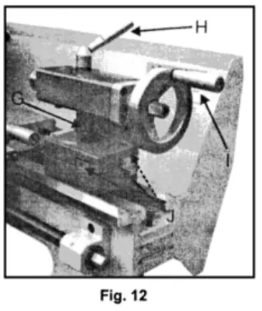
11. Tailstock Quill Clamping Lever (H, Fig. 12)
Rotate the lever clockwise to lock the spindle and counter-clockwise to unlock.
12. Tailstock Quill Traverse Handwheel (I, Fig. 12)
Rotate clockwise to advance the quill. Rotate counterclockwise to retract the quill
13. Tailstock Off-set Adjustment (J, Fig. 12)
Three sets screws located on the tailstock base are used to off-set the tailstock for cutting tapers. Loosen lock screw on tailstock end. Loosen one side set screw while tightening the other until the amount of off-set is indicated on scale. Tighten lock screw.
OPERATION
Replacement of Chuck
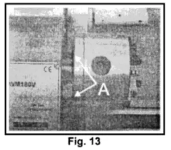
The head spindle holding fixture is cylindrical. Loose three set screws and nuts (A, Fig.13 only two are shown) on the lathe chuck flange to remove the chuck. Position the new chuck and fix it using the same set screws and nuts.
Tool Set-Up
Clamp the turning tool into the toolholder.
The tool must be clamped firmly. When turning, the tool has a tendency to bend under the cutting force generated during the chip formation. For best results, tool overhang should be kept to a minimum of 3/8" or less.
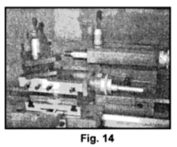
The cutting angle is correct when the cutting edge is in line with the center axis of the work piece. The correct height of the tool can be achieved by comparing the tool point with the point of the center mounted in the tailstock. If necessary, use steel spacer shims under the tool to get the required height. (Fig. 14)
Change Speed
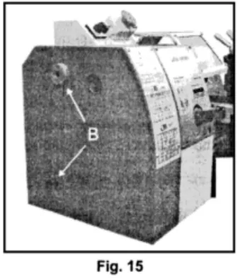
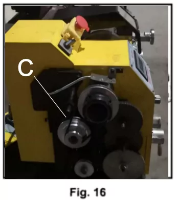
- Unscrew the two fastening screws (B, Fig.15 and remove the protective cover.
- Adjust the V-belt (C, Fig.16) corresponding position.
- Tighten the tension pulley and fasten the nut again.
Manual Turning
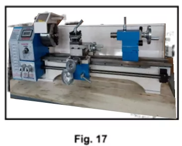
Apron travel, cross travel, and top slide handwheel can be operated for longitudinal or cross feeding (Fig.17).
Longitudinal Turning with Auto-Feed
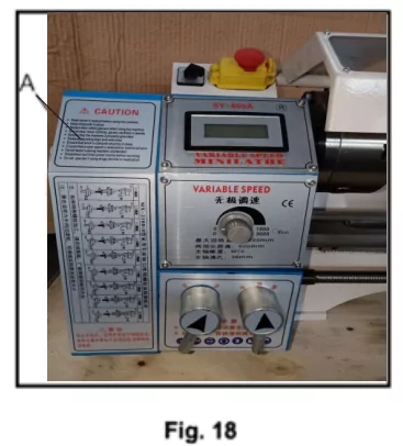
Use the table (A, Fig.18) on the lathe for selecting the feed speed or the thread pitch. Adjust the change gear if the required feed or thread pitch cannot be obtained with the installed gear set.
Change Gears
- Disconnect the machine from the power source.
- Unscrew the two fastening screws and remove the protective cover.
- Loosen the locking screw (B, Fig.19) on the quadrant.
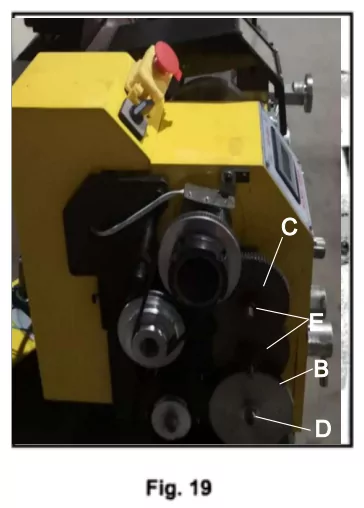
- Swing the quadrant (C, Fig.19) to the right.
- Unscrew the nut (D, Fig.29) from the leadscrew or the nuts (E, Fig.19) from the quadrant bolts in order to remove the change gears from the front.
- Install the gear couples according to the thread and feed table (Fig.20) and screw the gearwheels onto the quadrant again.
- Swing the quadrant to the left until the gearwheels have engaged again.
- Readjust gear backlash by inserting a normal sheet of paper as an adjusting or distance aid between the gearwheels.
- Immobilize the quadrant with the locking screw.
- Install the protective cover of the headstock and reconnect the machine to the power supply.
Thread Cutting Table
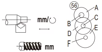
| |
0.50 |
0.75 |
1.00 |
1.25 |
| A B |
84 30 |
84 40 |
84 60 |
72 40 |
| C D |
H 60 |
H 60 |
H 50 |
H 60 |
| E F |
H 80 |
H 72 |
H 80 |
H 50 |
| |
1.50 |
1.75 |
2.00 |
2.50 |
| A B |
60 40 |
80 50 |
84 60 |
80 50 |
| C D |
H 80 |
H 72 |
H 50 |
H 60 |
| E F |
H 50 |
H 40 |
H 40 |
H 33 |
(When machining metric thread, It can be changed according to actual demand.)

| |
10 |
11 |
14 |
19 |
20 |
| A B |
60 H |
72 H |
52 H |
84 H |
72 33 |
| C D |
40 50 |
50 60 |
50 60 |
50 H |
50 H |
| E F |
H 52 |
H 52 |
H 80 |
60 H |
H 40 |
| |
22 |
28 |
38 |
40 |
44 |
| A B |
66 H |
72 H |
72 40 |
72 H |
66 H |
| C D |
52 60 |
50 30 |
H 52 |
52 33 |
60 30 |
| E F |
H 80 |
H 80 |
H 84 |
H 84 |
H 84 |
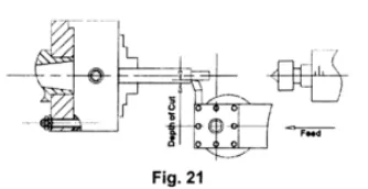
Straight Turning (Fig. 21)
In the straight turning operation, the tool feeds parallel to the axis of rotation of the workpiece. The feed can be either manual by turning the handwheel on the lathe saddle or the top slide, or by activating the automatic feed. The crossfeed for the depth of cut is achieved using the cross slide.
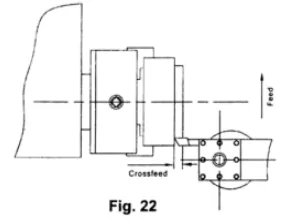
Facing and Recesses (Fig. 22)
In the facing operation, the tool feeds perpendicular to the axis of rotation of the workpiece. The feed is made manually with the cross slide handwheel. The crossfeed for cut depth is made with the top slide or lathe saddle.
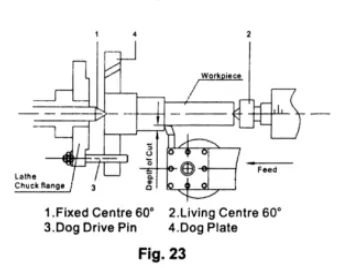
Turning Between Centers (Fig. 23)
For turning between centers, it is necessary to remove the chuck from the spindle. Fit the M.T.3 center into the spindle nose and the M.T.2 center into the tailstock. Mount the workpiece fitted with the driver dog between the centers. The driver is driven by a catch or face plate.
Note: Always use a small amount of grease on the tailstock center to prevent center tip form overheating.
Taper Turning Using Tailstock Off-Set
Work to a side angle of 5 can be turned by off-setting the tailstock. The angle depends on the length of the workpiece.
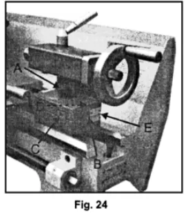
To off-set the tailstock, loosen locking screw (A, Fig24). Unscreen the set screw (B, Fig.24) on right end of the tailstock. Loosen the front adjusting screw(C, Fig.24) and take up the same amount by tightening the rear adjusting screw (D, Fig.24) until the desired taper has been reached. The desired cross-adjustment can be read off the scale. (E, Fig.24). First retighten the set screw (B, Fig.24) and then the two (front and rear) adjusting screw to lock the tailstock in position. Retighten the locking screw (A, Fig.24) of the tailstock. The workpiece must be held between to centers and driven by a face plate and driver dog.
After taper turning, the tailstock should be returned to its original position according to the zero position on the scale of tailstock. (E, Fig.24)
Thread Cutting
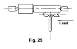
Set the machine up to the desired thread pitch (according to the threading chart, Fig.20). Start the machine and engage the half nut. When the tool reaches the part, it will cut the initial threading pass. When the tool reaches the end of the cut, stop the machine by turning the motor off and at the same time back the tool out of the part so that it clears the thread. Do not disengage the half nut lever. Reverse the motor direction to allow the cutting tool to traverse back to the starting point. Repeat these steps until you have obtained the desired results.
NOTES
Example: Male Thread
- The workpiece diameter must have been turned to the diameter of the desired thread. The workpiece requires a chamfer at the beginning of the thread and an undercut at the thread runout.
- The speed must be as low as possible.
- The change gears must have been installed according to the required pitch.
- The thread cutting tool must be exactly the sample shape as the thread, must be absolutely rectangular and clamped so that it coincides exactly with the turning center.
- The thread is produced in various cutting steps so that the cutting tool has to be turned out of the thread completely (with the cross slide) at the end of each cutting step.
- The tool is withdrawn with the leadscrew nut engaged by inverting the change-over switch.
- Stop the machine and feed the thread cutting tool in low cut depths using the cross slide.
- Before each passage, place the top slide approximately 0.2 to 0.3mm to the left and right alternately in order to cut the thread free. This way, the thread cutting tools cuts only on one thread flank with each passage. Keep cutting the thread free until you have almost reached the full depth of thread.
LATHE ACCESSORIES
Three Jaw Universal Lathe Chuck
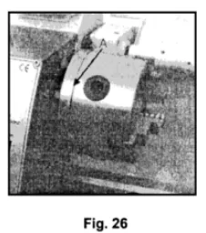
Using this universal chuck, round, triangular, square, hexagonal octagonal, and twelve-cornered stock may be clamped. (Fig.26)
Note: new lathes have very tight fitting jaws. This is necessary to ensure accurate clamping and long service life. With repeated opening and closing, the jaw adjust automatically and their operation becomes progressively smoother.
Note:
For the original 3-jaw chuck that mounted on the lathe, the factory has mounted the chuck in the best way to guarantee the holding accuracy with two "0" mark (A, Fig.26) showed on the chuck and chuck flange.
There are two types of jaws: Internal and external jaws. Please note that the number of jaws fit with the number inside the chuck's groove. Do not mix them together. When you are going to mount them, please mount them in ascending order 1-2-3, when you are going to take them out, be sure to take them out in descending order 3-2-1, one by one. After you finished this procedure, rotate the jaws to the smallest diameter and check that the three jaws are well fitted.
Four Jaw Independent Lathe Chuck
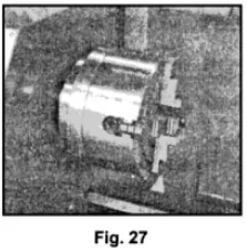
This special chuck has four independently adjustable chuck jaws. These permit the holding of asymmetrical pieces and enable the accurate set-up of cylindrical pieces. (Fig.27)
Drill Chuck (Optional)
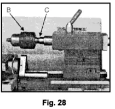
Use the drill chuck to hold centering drills and twist drills in the tailstock. (B, Fig.28)
Morse Taper Arbor (Optional)
An arbor is necessary for mounting the drill chuck in the tailstock. It has a No. 2 Morse taper. (C, Fig.28)
Live Center (Optional)
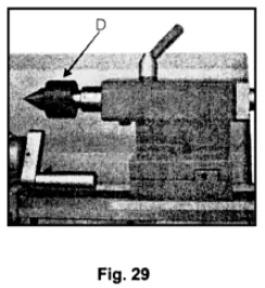
The live center is mounted in ball bearings. Its use is highly recommended for turning at speeds in excess of 600 RPM. (Fig.29)
ADJUSTMENT
After a period time, wear in some of the moving components may need to be adjust
Main Spindle Bearings
The main spindle bearings are adjusted at the factory. If end play becomes evident after considerable use, the bearings may be adjusted.
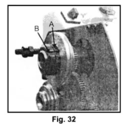
Fasten the slotted nut (A, Fig.32) on the back of the spindle,loosen the outer slotted nut (B, Fig.32). Adjust the slotted nut (A, Fig.32) until all end play is taken up. The spindle should still revolve freely. Fasten the slotted nut (A, Fig.32) again and tighten the outer slotted nut (B, Fig.32).
Caution: excessive tightening or preloading will damage the bearings.
Adjustment of Cross Slide
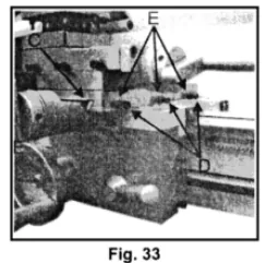
The cross slide is fitted with a gib strip (C, Fig.33) and can be adjusted with screws (D, Fig.33) fitted with lock nuts, (E, Fig.33) Loosen the lock nuts and tighten the set screws until slide moves freely without play. Tighten lock nuts to retain adjustment.
Adjustment of Top Slide
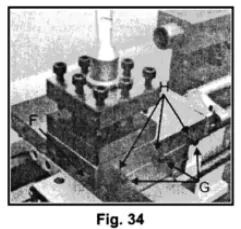
The top slide is fitted with a gib strip (F, Fig.34) and can be adjusted with screws (G, Fig.34) fitted with lock nuts. (H, Fig.34) Loosen the lock nuts and tighten the set screws until slide moves freely without play. Tighten lock nuts to retain adjustment.
Adjustment of Half Nut Guide
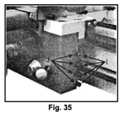
The half nuts engagement can be adjusted with screws (I, Fig.35) fitted with lock nuts (J, Fig.35). Loosen the nuts on the right side of the apron and adjust the control screws until both half nuts move freely without play. Tighten the nut.
LUBRICATION
CAUTION: Lathe must be serviced at all lubrication points and all reservoirs filled to operating level before the lathe is placed into service! Failure to comply may cause serious damage!
NOTES: Lubricate all slideways lightly before every use. Lubricate the change gears and the leadscrew slightly with a lithium-based grease.
1. Carriage
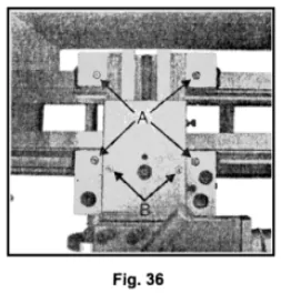
Lubricate Four oil ports (A, Fig. 36) with 20W machine oil once daily.
2. Cross Slide
Lubricate two oil ports (B, Fig. 36) with 20W machine oil once daily.
3. Leadscrew
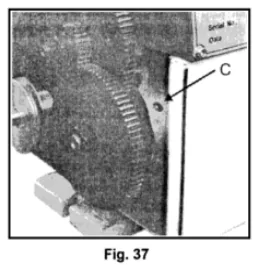
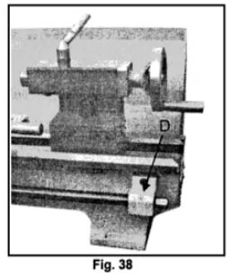
Lubricate the left oil port (C Fig. 37) and right oil port (D, Fig.38) with 20W machine oil once daily.
MAINTENANCE AND CLEANING
Keep the maintenance of the machine tool during the operation to guarantee the accuracy and service life of the machine tool.
1. In order to retain the machine's precision and functionality, it is essential to treat it with care, keep it clean and grease and lubricate it regularly. Only through good care, you can be sure that the working quality of the machine will remain constant.
NOTES: Disconnect the machine plug from the mains supply whenever you carry out cleaning, maintenance or repair work!
Oil, grease and cleaning agents are pollutants and must not be disposed of through the drains or in normal refuse. Dispose of those agents in accordance with current legal requirements on the environment. Cleaning rags impregnated with oil, grease and cleaning agents are easily inflammable. Collect cleaning rags or cleaning wool in a suitable closed vessel and dispose of them in an environmentally sound way - do not put them with normal refuse!
2. Lubrication all slideways lightly before every use. The change gears and the leadcrew must also be lightly lubricated with lithium base grease.
3. During the operation, the chips which falls onto the sliding surface should be cleaned timely, and the inspection should be often made to prevent chips falling into the position between the machine tool saddle and lathe bed guide way. Asphalt felt should be cleaned at certain time.
NOTES: Do not remove the chips with your bare hands. There is a risk of cuts due to sharp-edged chips. Never use flammable solvents or cleaning agents or agents that generate noxious fumes! Protect electrical components such as motors, switches, switch boxes, etc., against humidity when cleaning.
4. After the operation every day, eliminate all the chips and clean different part of the machine tool and apply machine tool oil to prevent rusting.
5. In order to maintain the machining accuracy, take care of the center, the surface of the machine tool for the chuck and the guide way and avoid mechanical damage and the wear due to improper guide.
6. If the damage is found, the maintenance should be done immediately.
NOTES: Repair work may only be carried out by qualified personnel with the corresponding mechanical and electrical knowledge.
TROUBLESHOOTING
| Problem |
Possible Reason |
Elimination |
| Surface of workpiece too rough |
Tool blunt
Tool springs
Feed too high
Radius at the tool tip too small |
Re-sharpen tool
Clamp tool with less overhang
Reduce feed
Increase radius |
| Workpiece becomes coned |
Centers are not aligned (tailstock has offset)
Top slide not aligned well (cutting with the top slide) |
Adjust tailstock to the center
Align top slide well |
| Lathe is chattering |
Feed too high
Slack in main bearing |
Reduce feed
Adjust the main bearing |
| Center runs hot |
Workpiece has expanded |
Loosen tailstock center |
| Tool has a short edge life |
Cutting speed too high
Crossfeed too high
Insufficient cooling |
Reduce cutting speed
Lower crossfeed (finishing allowance should not exceed 0.5mm)
More coolant |
| Flank wear too high |
Clearance angle too small
Tool tip not adjusted to center high |
Increase clearance angle
Correct height adjustment of the tool |
| Cutting edge breaks off |
Wedge angle too small (heat build-up)
Grinding crack due to wrong cooling
Excessive slack in the spindle bearing
Arrangement (vibrations) |
Increase wedge angle
Cool uniformly
Adjust the slack in the spindle bearing arrangement |
| Cut thread is wrong |
Tool is clamped incorrectly or has been started grinding the wrong way
Wrong pitch
Wrong diameter |
Adjust too to the center
Grind angle correctly
Adjust the right pitch
Turn the workpiece to the correct diameter |
| Spindle does not activate |
Emergency stop switch activated |
Unlock emergency stop switch |