Register
your product
www.kaercher.com/welcome
86446760 - B 03/12/21
Chariot 2 iVac 24 ATV
English 02
2
Warranty Registration
Thank you for purchasing a Kärcher North America product. Warranty registration is quick
and easy. Your registration will allow us to serve you better over the lifetime of the product.
To register your product go to :
http://warranty.karcherna.com
For customer assistance:
1-800-444-7654
8.644-676.0 Operator’s Manual - iVac 24 ATV
Machine Data Label / Overview
OVERVIEW
The Chariot® iVacuum 24™ is a battery powered, stand-on, wide area vacuum intended for commercial use. The
Chariot® iVacuum 24™ brushes and vacuums debris from indoor hard and carpeted surfaces and deposits the
debris in the debris tray and filter bags.
The unit also has an accessory wand and hose for cleaning small areas and non-floor surfaces.
Models:
1.008-067.0 iVACUUM 24, 130 A/H
1.008-068.0 iVACUUM 24, 114 A/H AGM
1.008-069.0 iVACUUM 24, 114 A/H AGM OBC
1.008-070.0 iVACUUM 24 OBC PACKAGING ONLY
1.012-617.0 iVACUUM 24, LITHIUM

3
Table of Contents
Machine Data Label / Overview . . . . . . . . . . . . . . . 2
Table of Contents. . . . . . . . . . . . . . . . . . . . . . . . . . . 3
How To Use This Manual. . . . . . . . . . . . . . . . . . . . . 4
Safety
Safety Label Locations . . . . . . . . . . . . . . . . . . . . . . 5
IMPORTANT SAFETY INSTRUCTIONS . . . . . . . . 6
HAZARD INTENSITY LEVEL . . . . . . . . . . . . . . . . . 8
Operations
Technical Specifications . . . . . . . . . . . . . . . . . . . . 10
How This Machine Works . . . . . . . . . . . . . . . . . . . 12
Components . . . . . . . . . . . . . . . . . . . . . . . . . . . . . 13
Drive Controls . . . . . . . . . . . . . . . . . . . . . . . . . . . . 14
Vacuum Controls. . . . . . . . . . . . . . . . . . . . . . . . . . 18
Pre-run Machine Inspection . . . . . . . . . . . . . . . . . 19
Emergency Stop Procedures . . . . . . . . . . . . . . . . 19
Normal Vacuuming . . . . . . . . . . . . . . . . . . . . . . . . 20
To Begin Vacuuming . . . . . . . . . . . . . . . . . . . . . . . 20
To Stop Vacuuming. . . . . . . . . . . . . . . . . . . . . . . . 21
Changing Vacuum Bag . . . . . . . . . . . . . . . . . . . . . 21
Maintenance
Service Schedule . . . . . . . . . . . . . . . . . . . . . . . . . 22
Batteries . . . . . . . . . . . . . . . . . . . . . . . . . . . . . . . . 23
Delta Q IC650 Charger Maintenance Instructions. 29
Delta Q IC650 Charger Operating Instructions . . 30
Selecting a Charge Profile. . . . . . . . . . . . . . . . . . . 31
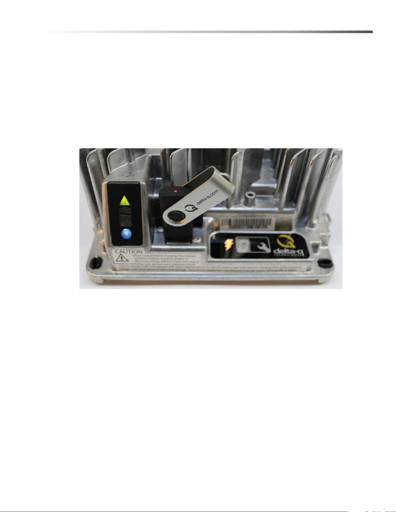
Configuring the IC650 Charger Using a USB Flash
Drive . . . . . . . . . . . . . . . . . . . . . . . . . . . . . . . . . .32
Charge Tracking Data. . . . . . . . . . . . . . . . . . . . . . .33
Lithium Battery (Optional) . . . . . . . . . . . . . . . . . . .34
Operating Limits . . . . . . . . . . . . . . . . . . . . . . . . . . .35
Handling . . . . . . . . . . . . . . . . . . . . . . . . . . . . . . . . .36
Installation - Single Battery . . . . . . . . . . . . . . . . . . .36
Installation. . . . . . . . . . . . . . . . . . . . . . . . . . . . . . . .36
Operation . . . . . . . . . . . . . . . . . . . . . . . . . . . . . . . .36
On–Off . . . . . . . . . . . . . . . . . . . . . . . . . . . . . . . . . .36
Charging . . . . . . . . . . . . . . . . . . . . . . . . . . . . . . . . .37
Discharging . . . . . . . . . . . . . . . . . . . . . . . . . . . . . . .37
Storage . . . . . . . . . . . . . . . . . . . . . . . . . . . . . . . . . .37
Protection & Faults . . . . . . . . . . . . . . . . . . . . . . . . .37
Faults & Corrective Actions . . . . . . . . . . . . . . . . . .37
Service & Maintenance . . . . . . . . . . . . . . . . . . . . . .38
Troubleshooting . . . . . . . . . . . . . . . . . . . . . . . . . . .38
Circuit Protection. . . . . . . . . . . . . . . . . . . . . . . . . . .40
Vacuum Diverter Valve Maintenance . . . . . . . . . . .41
Brush Removal . . . . . . . . . . . . . . . . . . . . . . . . . . . .43
Brush Installation . . . . . . . . . . . . . . . . . . . . . . . . . .43
Debris Tray Removal . . . . . . . . . . . . . . . . . . . . . . .43
Debris Tray Installation . . . . . . . . . . . . . . . . . . . . . .43
Belt Replacement . . . . . . . . . . . . . . . . . . . . . . . . . .43
Remove Brush Deck . . . . . . . . . . . . . . . . . . . . . . . .44
Replace Brush Deck Motor . . . . . . . . . . . . . . . . . . .44
Brush Motor Carbon Brush Replacement . . . . . . . .44
Drive Motor . . . . . . . . . . . . . . . . . . . . . . . . . . . . . . .46
Drive Motor Carbon Brush Replacement . . . . . . . .46
Drive Chain Tension . . . . . . . . . . . . . . . . . . . . . . . .46
Machine Tie-Downs . . . . . . . . . . . . . . . . . . . . . . . .48
Troubleshooting . . . . . . . . . . . . . . . . . . . . . . . . . . .49
Battery Discharge Indicator Troubleshooting . . . . .51
Suggested Spare Parts. . . . . . . . . . . . . . . . . . . . . 52
8.644-676.0 Operator’s Manual - iVac 24 ATV
4
How To Use This Manual
This manual contains the following sections:
• How to Use This Manual
•Safety
• Operations
• Maintenance
The HOW TO USE THIS MANUAL section will tell you
how to find important information for ordering correct
repair parts.
Parts may be ordered from authorized dealers. When
placing an order for parts, the machine model and
machine serial number are important. Refer to the
MACHINE DATA box which is filled out during the
installation of your machine. The MACHINE DATA box
is located on the inside of the front cover of this manual.
The model and serial number of your machine is
located on the back of the machine.
The SAFETY section contains important information
regarding hazardous or unsafe practices of the
machine. Levels of hazards are identified that could
result in product damage, personal injury, or severe
injury resulting in death.
The OPERATIONS section is to familiarize the operator
with the operation and function of the machine.
The MAINTENANCE section contains preventive main-
tenance to keep the machine and its components in
good working condition. They are listed in this general
order:
• Batteries
•Brush Deck
• Drive Motor
• Service Schedule
• Machine Troubleshooting
The manual part number is located on the lower right
corner of the front cover.
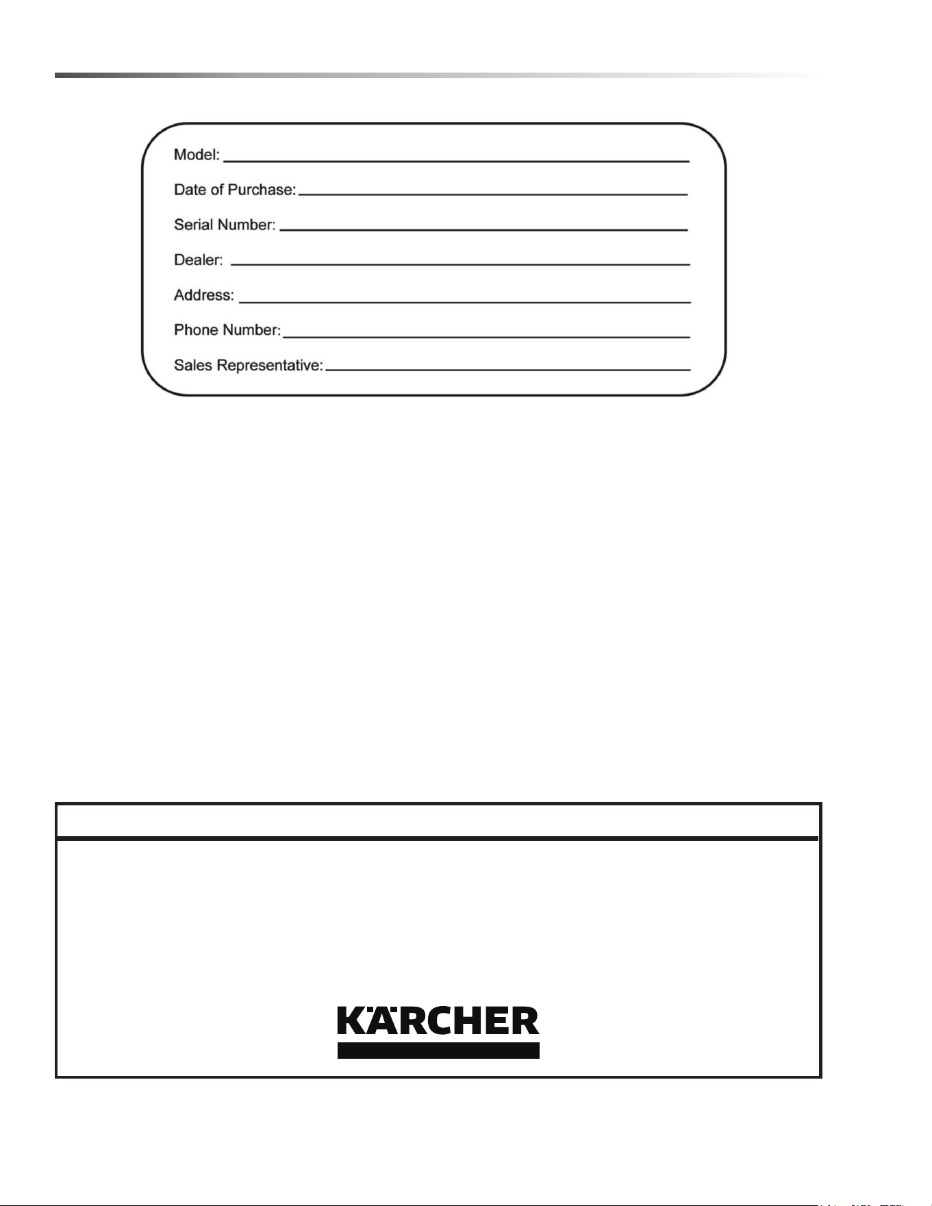
Model:
Date of Purchase:
Serial Number:
Dealer:
Address:
Phone Number:
Sales Representative:
8.644-676.0 Operator’s Manual - iVac 24 ATV
5
Safety
8.644-676.0 Operator’s Manual - iVac 24 ATV
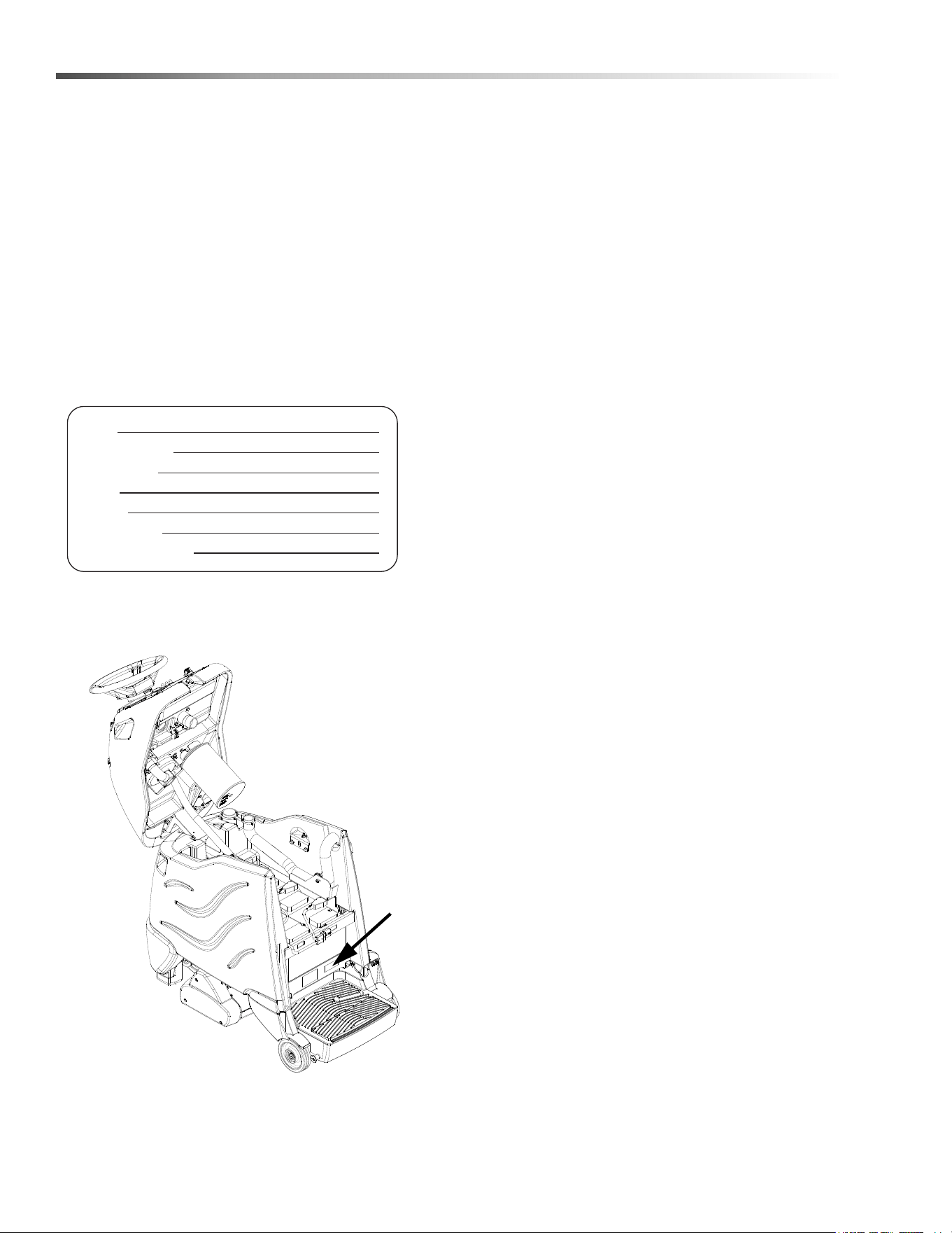
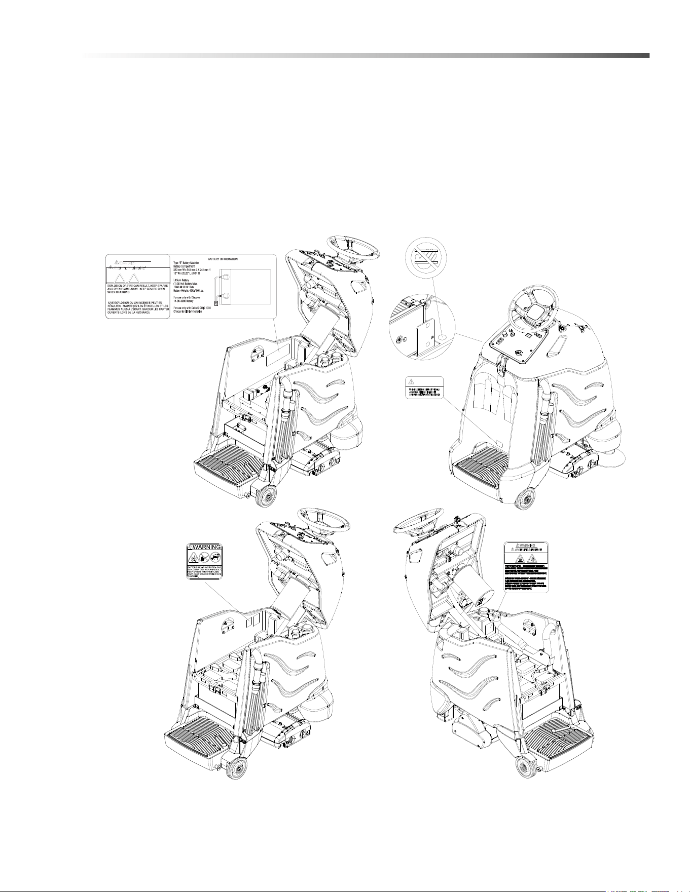
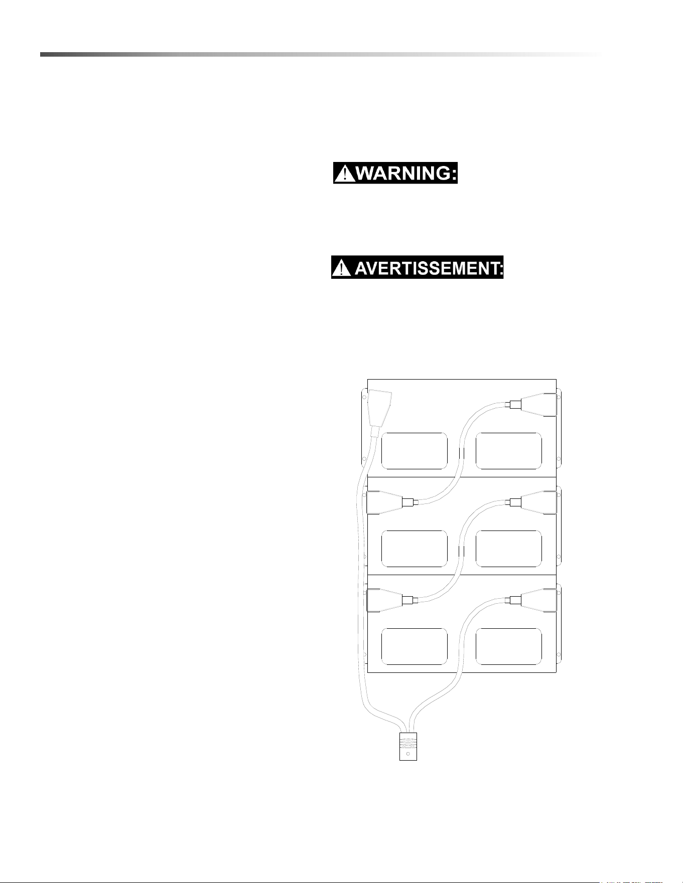
Safety Label Locations
These drawings indicate the location of safety labels on the machine. If at any time the labels become illegible,
promptly replace them.
Emplacement De L'étiquette De Sécurité
REMARQUE : Ces dessins indiquent l'emplacement des étiquettes de sécurité sur la machine. Si, à tout moment,
les étiquettes deviennent illisibles, contactez votre représentant autorisé pour un remplacement rapide.
LITHIUM WARNING LABEL
86441180
86385070
WARNING
MOVING PARTS
CAUTION LABEL
86335010
(ON BOARD CHARGER
MODELS ONLY)
CAUTION
CAUTION LABEL
86244310
CAUTION
BATTERY
86252520

6
Safety
IMPORTANT SAFETY INSTRUCTIONS
When using this machine, basic precaution
must always be followed, including the following:
READ ALL INSTRUCTIONS BEFORE USING THIS MACHINE.
To reduce the risk of fire, electric shock, or injury:
Use only indoors. Do not use outdoors or expose to rain.
Use only as described in this manual. Use only manufacturer's recommended components and attachments.
If the machine is not working properly, has been dropped, damaged, left outdoors, or dropped into water, return it to
an authorized service center.
Do not operate the machine with any openings blocked. Keep openings free of debris that may reduce airflow.
This machine is not suitable for picking up hazardous dust.
Do not operate this machine near flammable fluids, dust or vapors. Do not expose to fire.
Maintenance and repairs must be done by qualified personnel.
If foam or liquid comes out of machine, switch off immediately.
Disconnect battery before cleaning or servicing.
Do not use a visibly damaged battery pack or appliance. If the battery housing is damaged, do not touch exposed
contents.
Do not modify or attempt to repair the appliance or the battery pack.
Lithium Battery Option: For use only with Discover Lithium battery 12-36-6700 and Delta Q QuiQ 1000 Charger with
lithium algorithm.
Before the machine is discarded, the batteries must be removed and properly disposed of.
Make sure all warning and caution labels are legible and properly attached to the machine.
During operation, attention shall be paid to other persons, especially children.
Before use, all covers and doors shall be put in the positions specified in the instructions.
When leaving unattended, secure against unintentional movement.
The machine shall only be operated by instructed and authorized persons.
When leaving unattended, switch off or lock the main power switch to prevent unauthorized use.
Only chemicals recommended by the manufacturer shall be used.
This appliance has been designed for use with the brushes specified by the manufacturer. The fitting of other
brushes may affect its safety.
Do not use on surfaces having a gradient of over 10% (6 degrees).
READ AND SAVE THESE INSTRUCTIONS
8.644-676.0 Operator’s Manual - iVac 24 ATV

7
Safety
MESURES DE SÉCURITÉ IMPORTANTES
Lors de l'utilisation d'un appareil à batteries, il est nécessaire de respecter systématique-
ment des mesures de sécurité de base, comme suit :
NOTE DE TOUTES CES MESURES AVANT D'UTILISER CETTE MACHINE.
Pour réduire les risques d'incendie, de chocs électriques, ou de blessures :
Ne jamais l'utiliser à l'extérieur ou dans la pluie.
Utiliser cet appareil conformément aux instructions du présent manuel uniquement. N'utiliser que les composants
et les accessoires conseillés par le fabricant.
Lorsque la machine ne fonctionnant pas correctement, a fait l'objet d'une chute ou d'une détérioration, a été laissée
à l'extérieur, est tombée dans l'eau, la retourner au centre de service agréé.
Ne pas opérer la machine lorsque les conduits de ventilation sont bloquées. Débarrasser les débris des conduits,
car ils peuvent réduire l'écoulement d'air.
Cette machine n'est pas adaptée au ramassage de poussières dangereuses
Ne pas l'utiliser près de liquides, de poussières ou de vapeurs inflammables. Ne pas exposer au feu.
L'entretien et les réparations de la machine doivent être effectuées par un personnel qualifié.
Si de la mousse ou du liquide sort de la machine, la mettre hors tension immédiatement.
Déconnecter les batteries avant de nettoyer la machine ou de la soumettre à un entretien.
Ne pas utiliser de bloc-batterie ni d'appareil visiblement endommagé. Si le compartiment de batterie est
endommagé, ne pas toucher au contenu exposé.
Ne pas modifier ni tenter de réparer l'appareil ou le bloc-batterie.
Option pour batterie lithium-ion: Pour utilisation avec batterie au lithium Discover 12-36-6700 et chargeur Delta Q
QuiQ 1000 avec un algorithme au lithium.
Avant de se débarrasser de la machine, il est nécessaire de retirer les batteries et de les jeter correctement.
S'assurer que toutes les plaques d'avertissement ou de précaution sont lisibles et fixées correctement sur la
machine.
Durant la manoeuvre de la machine, prendre garde aux personnes environnantes et notamment aux enfants.
Avant l'utilisation de la machine, veiller à positionner tous les couvercles et portes comme indiqué dans les instruc-
tions.
Lorsque la machine est laissée sans surveillance, s'assurer qu'elle ne se déplace pas de manière accidentelle.
Cette machine ne doit être manoeuvrée que par un personnel expérimenté et qualifié.
Lorsque la machine est laissée sans surveillance, la mettre hors tension ou verrouiller l'interrupteur principal afin
d'empêcher un emploi non autorisé.
Seuls les produits chimiques recommandés par le fabricant doivent être utilisés.
Cette machine a été conçue pour être utilisée avec des brosses spécifiées par le fabricant. L'utilisation d'autres
brosses peut affecter sa sûreté.
N'employez pas sur des surfaces ayant un gradient de plus de 10% (6 degrés).
CONSERVER CES INSTRUCTIONS
8.644-676.0 Operator’s Manual - iVac 24 ATV

8
Safety
8.644-676.0 Operator’s Manual - iVac 24 ATV
The following symbols are used throughout this guide as indicated in their descriptions:
HAZARD INTENSITY LEVEL
There are three levels of hazard intensity identified by signal words -WARNING and CAUTION and FOR SAFETY.
The level of hazard intensity is determined by the following definitions:
WARNING - Hazards or unsafe practices which COULD result in severe personal injury or death.
CAUTION - Hazards or unsafe practices which could result in minor personal injury or product or property damage.
FOR SAFETY: To Identify actions which must be followed for safe operation of equipment.
Report machine damage or faulty operation immediately. Do not use the machine if it is not in proper operating
condition. Following is information that signals some potentially dangerous conditions to the operator or the equip-
ment. Read this information carefully. Know when these conditions can exist. Locate all safety devices on the
machine. Please take the necessary steps to train the machine operating personnel.
FOR SAFETY:
DO NOT OPERATE MACHINE:
Unless Trained and Authorized.
Unless Operation Guide is Read and understood.
In Flammable or Explosive areas.
In areas with possible falling objects.
WHEN SERVICING MACHINE:
Avoid moving parts. Do not wear loose clothing; jackets, shirts, or sleeves when working on the machine. Use
Kärcher North America approved replacement parts.
Batteries emit hydrogen gas. Explosion or fire can result. Keep sparks and open flame away. Keep battery
compartment open during charging. Keep sparks and flames away from the batteries. Do not smoke around
batteries.
Disconnect batteries before working on machine. Only qualified personnel should work inside machine.
Always wear eye protection and protective clothing when working on or near batteries. Avoid skin contact
with the acid contained in the batteries.
Never allow metal to lie across battery tops.
9
Safety
Les symboles ci-dessous sont utilisés à travers ce manuel comme illustré dans leurs descriptions :
DEGRÉS DE RISQUES EN CAS DE DANGER
Il existe trois degrés de risques identifiés par les termes signalétiques -AVERTISSEMENT et ATTENTION et POUR
VOTRE SÉCURITÉ. Le degré de risque est défini de la manière suivante:
AVERTISSEMENT - Dangers ou méthodes dangereuses qui POURRAIENT provoquer de graves blessures ou
entraîner la mort.
ATTENTION - Dangers ou méthodes dangereuses qui pourraient provoquer des blessures légères ou une détério-
ration du produit ou des biens immobiliers.
POUR VOTRE SÉCURITÉ: ce signe permet d'identifier les mesures de précaution à prendre pour assurer un bon
fonctionnement du matériel.
Rendre compte immédiatement d'une défaillance ou d'une détérioration de la machine. Ne pas utiliser la machine
si celle-ci ne fonctionne pas correctement. Lire soigneusement les informations ci-dessous signalant certains
dangers potentiels pour l'opérateur de la machine. L'opérateur doit être absolument au courant de ces dangers
potentiels. Localiser tous les dispositifs de sécurité sur la machine. Il est conseillé de prendre les mesures néces-
saires pour former le personnel opérateur.
POUR VOTRE SÉCURITÉ:
NE PAS MANOEUVRER LA MACHINE:
Lorsqu'on n'est pas expérimenté ou qualifié.
Lorsque le guide d'utilisation n'est pas été lu ou compris.
Dans des zones inflammables ou explosives.
Dans des zones où des objets peuvent tomber.
LORS DE L'ENTRETIEN DE LA MACHINE:
Éviter les parties amovibles. Ne pas porter de vêtements amples, tels que des vestes, des chemises ou des
vêtements avec manches lors de l'utilisation de la machine. Utiliser les pièces détachées Kärcher North America
homologuées.
Les batteries émettent le gaz d'hydrogène. L'explosion ou le feu peut résulter. Étincelles de subsistance et
flamme nue loin. Compartiment de batterie de subsistance ouvert en chargeant. Étincelles et flammes de
subsistance loin des batteries. Ne fumez pas autour des batteries.
Déconnecter les batteries avant de travailler sur la machine. La machine ne doit être confiée qu'à un
personnel qualifié. Porter systématiquement des lunettes et des vêtements de protection lors d'une inter-
vention sur les batteries ou aux alentours. Éviter tout contact de la peau avec l'acide contenu dans les
batteries.
Ne jamais placer d'objets métalliques sur le dessus des batteries.
8.644-676.0 Operator’s Manual - iVac 24 ATV

10
Operations
Technical Specifications
ITEM DIMENSION/CAPACITY
Nominal power 1224 W
Rated Voltage 36 Volts DC
Rated Amperage 34 amps
Batteries 3 X12 Volt 130 AH @ 20 hr. rate
Battery Compartment Dimensions 20-1/2 in. x 13 in. x 10 in. tall (330mm x 521mm x 254mm)
Battery, Lithium 38.4 Volts
Battery, Lithium - Dimensions (330 mm x 339 mm x 256 mm)
Propelling Motor .38 HP (280 W)
Cylindrical Brush Motor .5 HP (373 W)
Side Broom Motor .06 HP (47W)
Cylindrical Brushes Two 20 in. (51cm) by 4 in. (10cm) diameter
Side Broom 9 in. (229 mm) diameter
Cylindrical Brush speed 1030 RPM
Side Broom speed 90 RPM
Vacuum Motor .63 HP (470 W)
Maximum flow rate of vacuum motor 72 cfm (33.98 liters per second)
Maximum suction of vacuum motor 47.3 inches of water (11.7 kPa)
Bag Capacity 1100 in³ 18L
Mass (GVW) 613 lbs (280 kg)
Weight empty without batteries 250 lbs (115 kg)
Tires 8 in. (203mm) drive, 6 in. (156mm) rear, polyurethane
Maximum Speed 2.3 mph (3.7 KPH)
Brake Electrical parking brake,sets automatically whenever operator stops.
Minimum aisle u-turn width 51 in. (1295 mm)
Maximum rated climb and descent angle 10% (6 degrees)
Sound power dBA (IEC 60704-1) 80.6 dBA
Sound pressuer dBA (IEC 60704-1) 68.4 dBA
Vibration arms m/s² (ISO 5344) 1.6 m/s²
Vibration feet m/s² (ISO 5344) 0.54 m/s²
Sound power uncertainty dBA 3.00 dBA
Sound pressure uncertainty dBA 3.00 dBA
Vibration uncertainty m/s² 0.50 m/s²
8.644-676.0 Operator’s Manual - iVac 24 ATV
11
Operations
This appliance is not intended for use by persons (including children) with reduced physical, sensory or
mental capabilities, or lack of experience and knowledge, unless they have been given supervision or
instruction concerning use of the appliance by a person responsible for their safety. Children should be
supervised to ensure that they do not play with the appliance.
Cet appareil n'est pas prévu à l'usage des personnes (enfants y compris) avec des possibilités physiques,
sensorielles ou mentales réduites, ou le manque d'expérience et de connaissance, à moins qu'ils aient été
donnés la surveillance ou l'instruction au sujet de l'utilisation de l'appareil par une personne chargée de
leur sûreté. Des enfants devraient être dirigés pour s'assurer qu'ils ne jouent pas avec l'appareil.
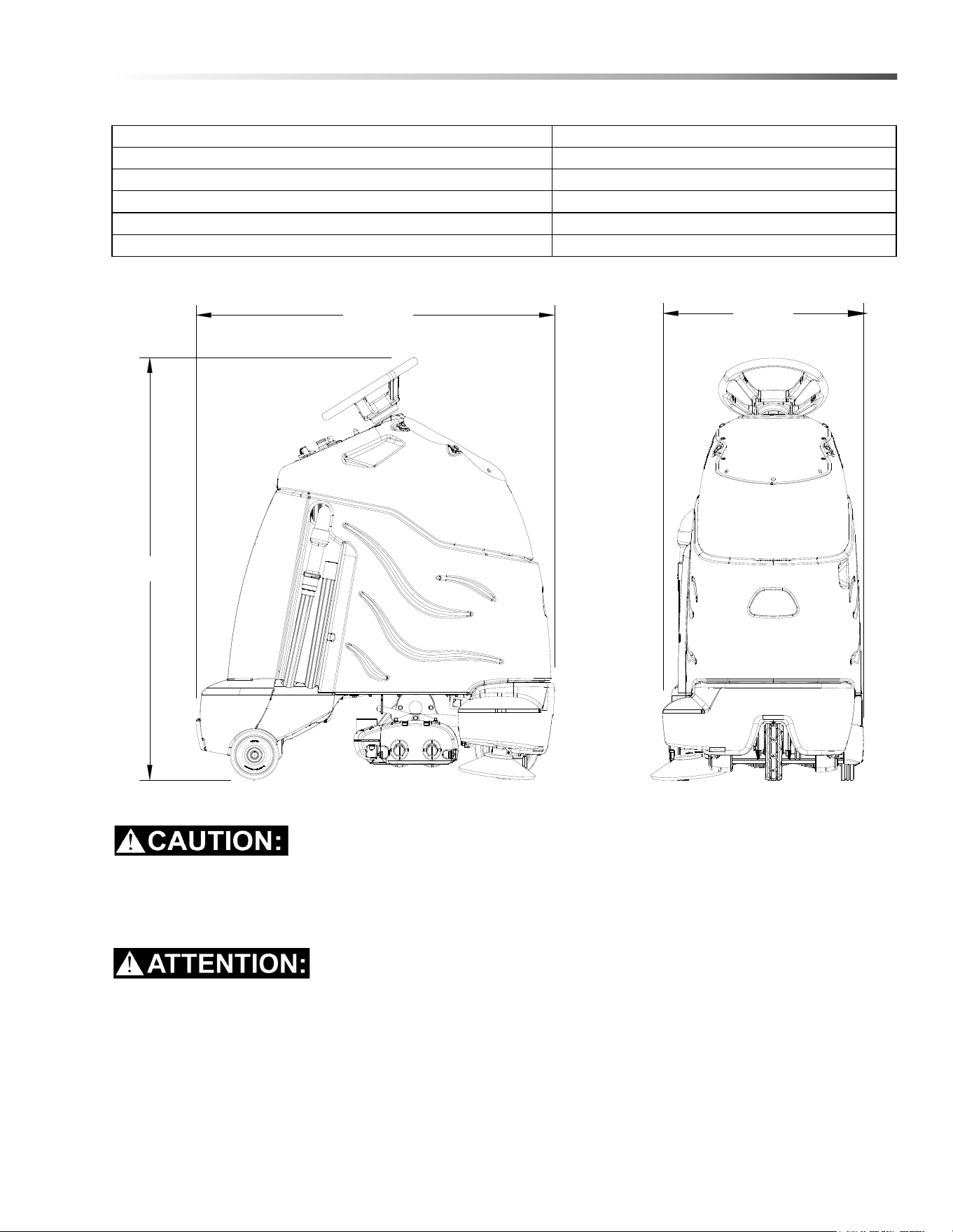
ITEM MEASURE
Height 51.8 in (1316 mm)
Length 44.0 in (1118 mm)
Width without deck 24.5 in (622 mm)
Width of deck 23.25 in (581 mm)
Width with side broom 25.9 in (658 mm)
LENGTH
WIDTH
HEIGHT
8.644-676.0 Operator’s Manual - iVac 24 ATV

12
Operations
How This Machine Works
The Chariot® iVacuum 24 ATV™ is a battery powered,
self-propelled, vacuum intended for commercial use.
The appliance vacuums debris and dirt from the carpet
and collects it in a disposable bag.
The machine's primary systems are the brush system,
vacuum system, and operator control system.
The function of the brush system is to brush the carpet.
The brush system consists of two cylindrical type
brushes, side brush, motors, brush deck, and controls.
The right side brush is used to sweep debris from along
edges into the path of the brush deck.The front
cylindrical brush sweeps debris backwards. The rear
brush sweeps debris forwards. Both cylindrical brushes
work to agitate the carpet and to route the debris up
into the debris tray assembly.
The function of the vacuum system is to vacuum fine
dirt and debris into the vacuum bag. The recovery
system consists of the debris tray assembly, vacuum
motor, paper vacuum bag and post filter. The vacuum
draws the dirt off the floor as the machine moves
forward. The vacuum motor provides suction to draw
the fine dirt into the vacuum bag, and the debris tray
holds large debris. The vacuum bag holds the fine dirt.
The function of the operator control system is to control
the direction and speed of the machine. The directional
control system consists of the direction control switch,
throttle pedal, speed control switch, drive reset switch,
emergency stop/brake switch, steering wheel, propel
controller and drive wheel. The directional control
switch signals forward or reverse direction. The
controller interprets signals from the throttle pedal to
command the drive wheel to propel or slow the
machine. The drive reset switch is to make sure the
operator is on platform before machine will propel. The
steering wheel points the drive wheel in the direction
desired by the operator. The parking brake
automatically engages when the operator steps off the
platform. The emergency stop/brake can be used to
hold the machine on slopes.
8.644-676.0 Operator’s Manual - iVac 24 ATV
13
Operations
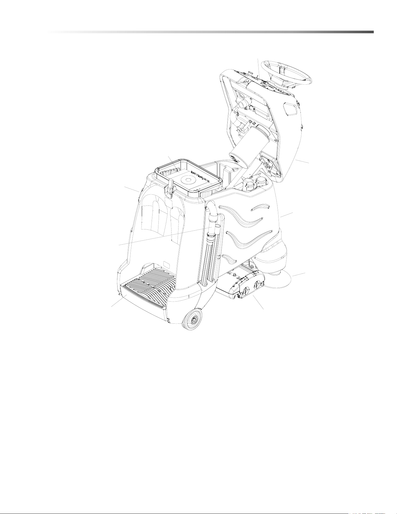
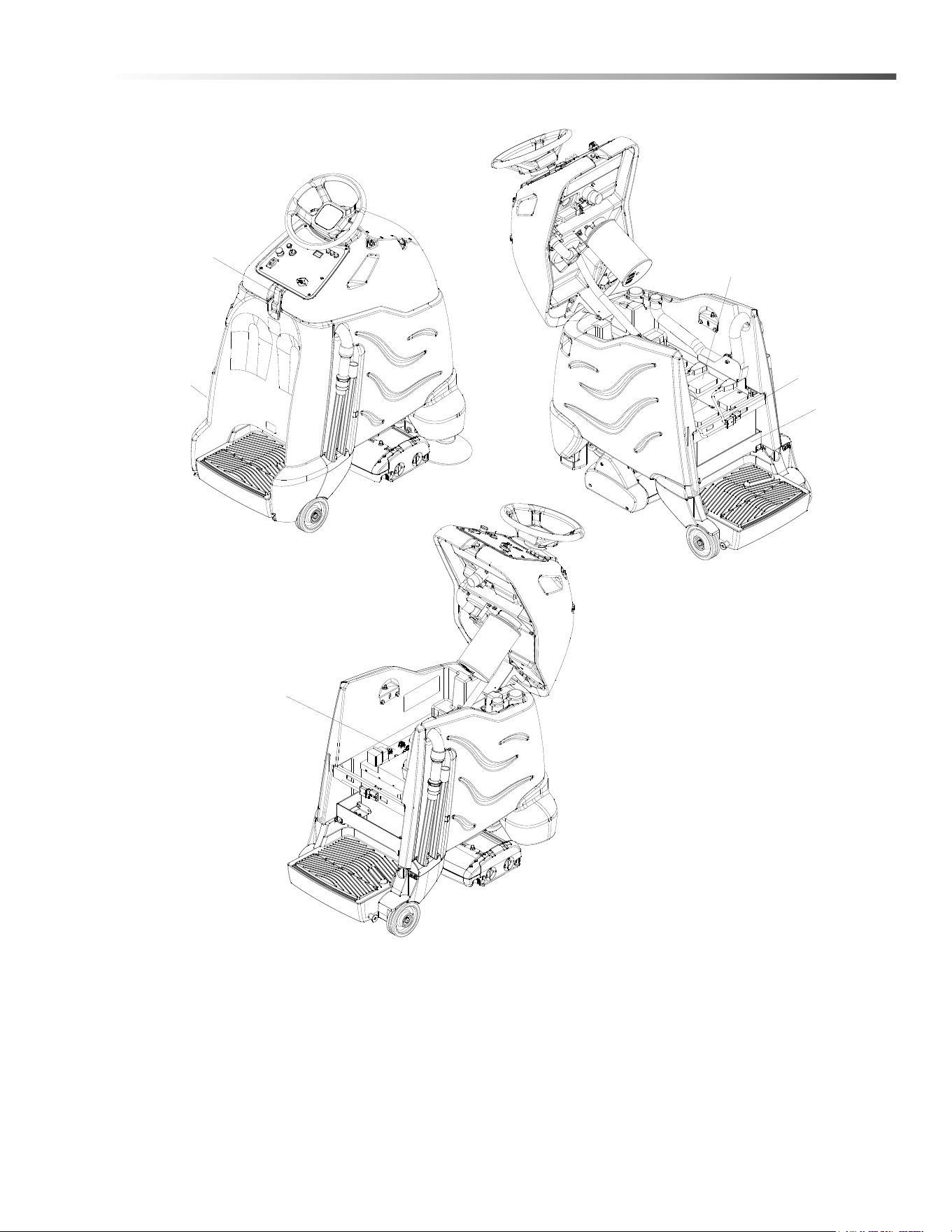
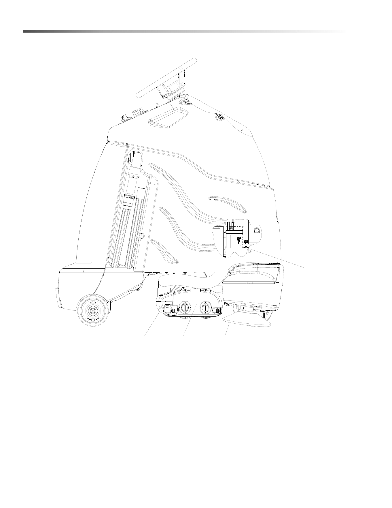
Components
1. Accessory Hose
2. Brush Deck
3. Console
4. Control Panel
5. Main Cover
6. Pedal Platform
7. Rear Cover
8. Side Broom
9. Vacuum Bag
1
2
3
4
5
6
7
8
9
8.644-676.0 Operator’s Manual - iVac 24 ATV
14
Operations
Drive Controls
1
2
3
4
5
6
7
8
9
10
8
8.644-676.0 Operator’s Manual - iVac 24 ATV

15
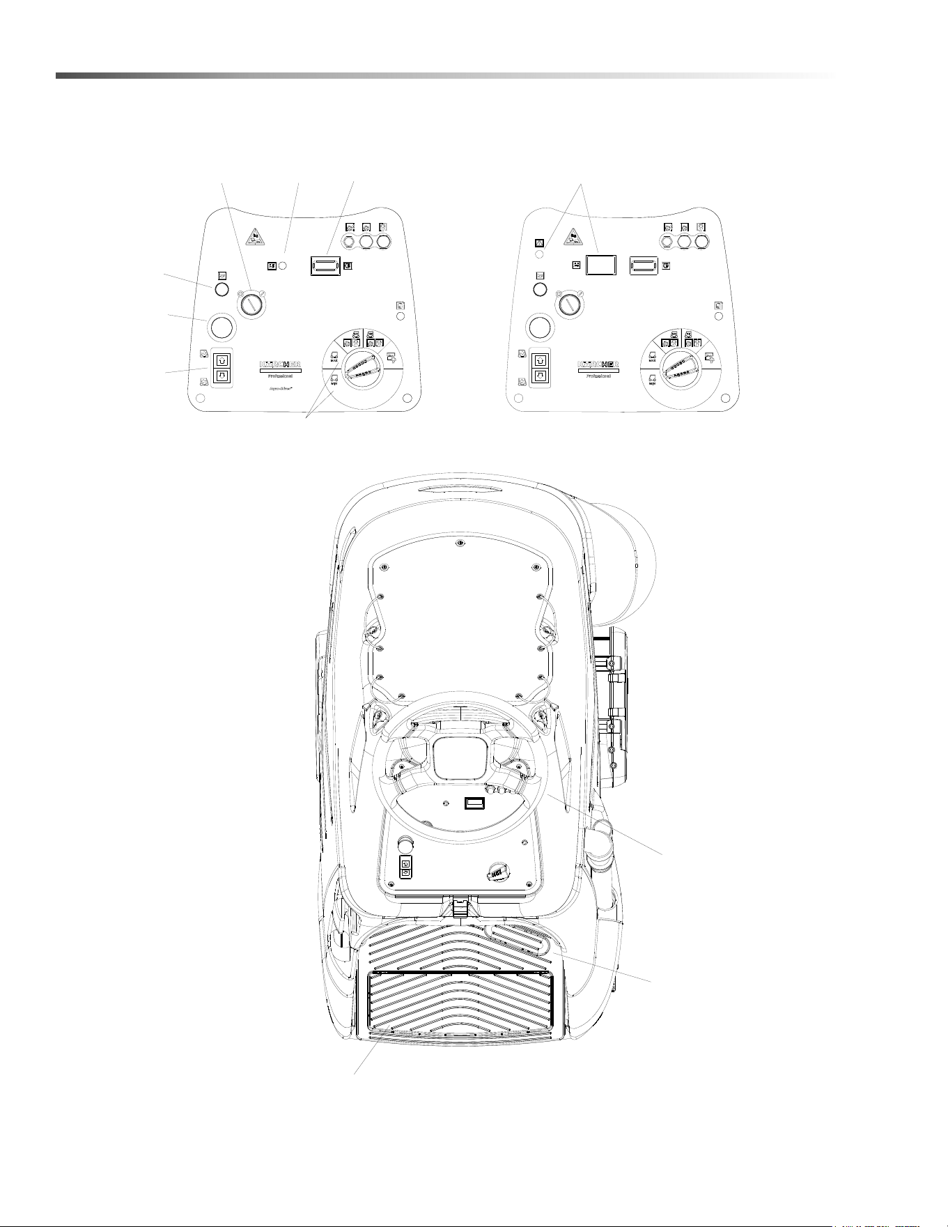
Operations
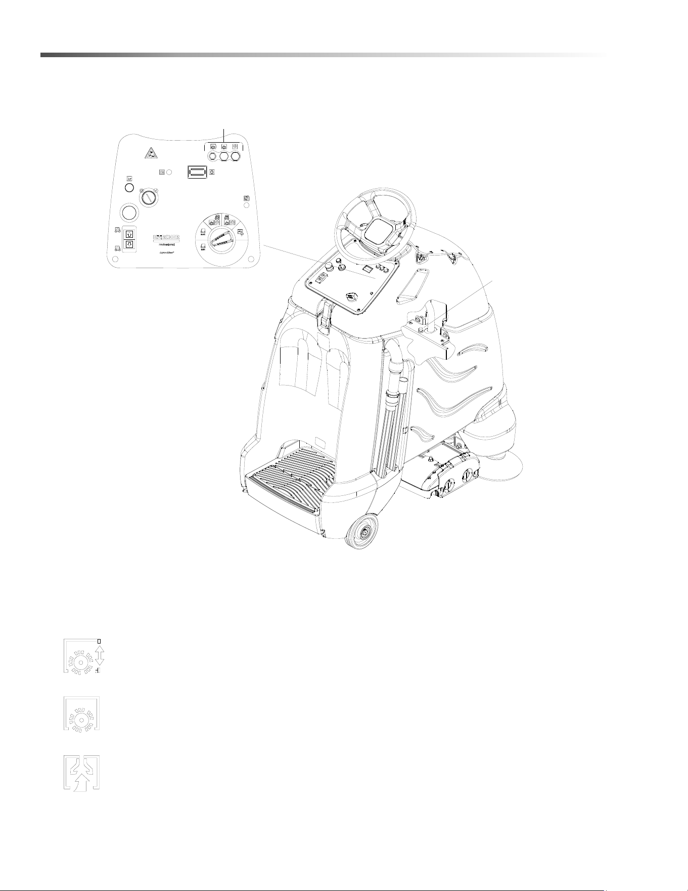
1. Key Switch
2. Emergency Stop/Brake Switch
3. Directional Control / Drive Reset Switch
4. Throttle Pedal
5. Horn Button
6. Steering Wheel
7. Speed Control
8. Battery Discharge Indicator Light
9. Hour Meter
10. Operator Presence Switch
1. KEY SWITCH
Controls the power for machine functions.
To turn the machine power on, rotate key clockwise.
To turn the machine off, rotate key counterclockwise.
When the key is turned on the battery discharge indicator light will flash once and stay on continuously.
2. EMERGENCY STOP/BRAKE SWITCH
This safety feature is designed to cut all power to the machine at any time and apply parking brake.
To shut the machine power off, push the Emergency Stop Switch, this will also engage the parking brake and
cause the machine to stop immediately.
To reset the machine, rotate the switch clockwise. The switch will pop-up indicating reset machine.
3. DIRECTIONAL CONTROL / DRIVE RESET SWITCH
This safety feature is designed to ensure safe engagement of propel drive. Each time the machine power is
turned on, or each time an operator steps on to the platform, the Drive Reset Switch must be pushed before
machine will propel.
The switch controls the direction of travel of the vehicle. The lighted arrow on the switch indicates direction of
travel.
To travel forward, press the top of the switch.
To travel in reverse, press the bottom of the switch.
8.644-676.0 Operator’s Manual - iVac 24 ATV

16
Operations
4. THROTTLE PEDAL
Controls the speed of the vehicle within the speed control setting selected. Pressing the pedal causes the
machine to travel in the direction selected by the Directional Control Switch.
To increase speed, increase pressure on the pedal.
To decrease speed, decrease pressure on the pedal.
5. HORN BUTTON
The horn is activated by pressing the horn button.
6. STEERING WHEEL
The steering wheel turns the front wheel causing the machine to change direction.
7. SPEED CONTROL
Controls the maximum speed of the machine. There are two travel-only settings, slow and fast.
To change speed, rotate the dial to either slow or fast position. The slow position is to the left (counterclock-
wise), fast to the right (top position).
The throttle pedal will always regulate the speed between 0 and maximum.
8.644-676.0 Operator’s Manual - iVac 24 ATV

17
Operations
8. BATTERY DISCHARGE INDICATOR
WET AND AGM
Indicates the charge level of the batteries.
The indicator will be illuminated if the batteries have a sufficient charge. A slow, continous flash indicates the
batteries require charging.
LITHIUM
Indicates the charge level of the batteries. The meter display is divided into 10 bars. Bars illuminated on the far
right indicate full charge. Bars flashing near the left side indicate the batteries should be recharged. Further
operation of the machine could damage the machine or the batteries.
ALL BATTERIES
The Battery Lockout function will activate when the batteries are low.
Once active, the LED status indicator will begin to flash slowly and the controller will inhibit the side broom,
main brushes, and vacuum operation. The drive remains functional. Return the unit to the charging station and
charge the batteries.
NOTE: Continuing usage may damage the batteries.
When the machine is left overnight with less than a full charge, the display may initially indicate a full charge. It
will also indicate a full charge if the batteries are disconnected, then reconnected. After a few minutes of
operation the indicator will give the correct charge level.
9. HOUR METER
Records the number of hours the machine has been in vacuum operation. This information is useful in deter-
mining when to service the machine.
8.644-676.0 Operator’s Manual - iVac 24 ATV
18
Operations
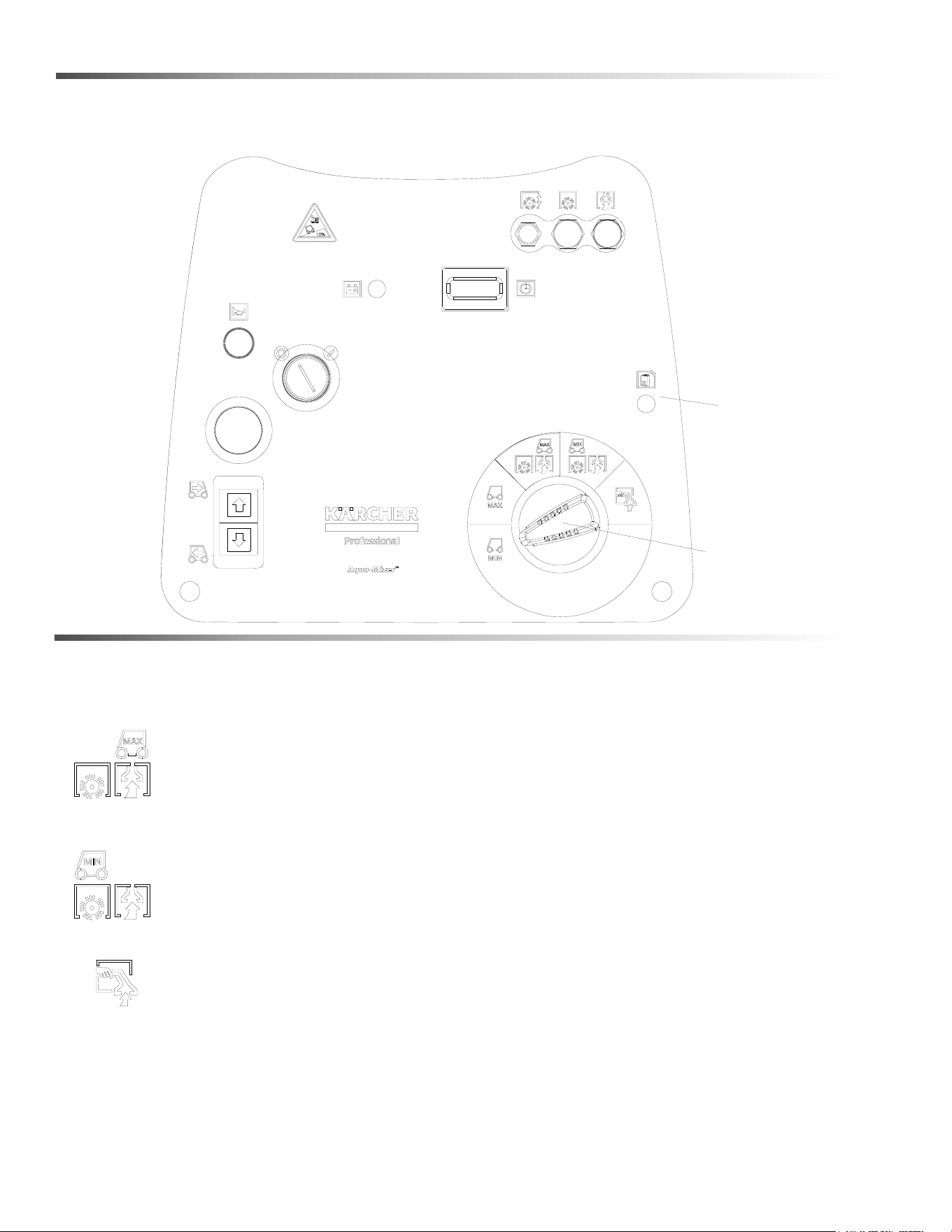
Vacuum Controls
1. Function Mode Switch
The first two positions are for transport only. See drive controls section.
Light vacuuming
This mode is used for light vacuuming. In this mode the machine will propel at fast speed. The
‘floating’ brush deck is in the down position. The brushes will agitate, the side broom will bring
debris into the path of the deck. The vacuum will draw the dirt and debris into the debris tray and
the vacuum bag.
Deep vacuuming
This mode is used for deep vacuuming. In this mode the machine will propel at a slow speed. The
‘floating’ brush deck is in the down position. The brushes will agitate, the side broom will bring
debris into the path of the deck. The vacuum will draw the dirt and debris into the debris tray and
the vacuum bag.
Accessory mode
This mode is used for using the accessory hose and attachments only. The brush and vacuum
deck will both be up and off. In this mode the machine will not propel.
2. Vacuum Bag Status Light
Light is green when bag is in place and vacuum operating conditions are good.
Light is red if bag is missing or full or vacuum operating conditions are poor.
1
2
8.644-676.0 Operator’s Manual - iVac 24 ATV

19
Operations
Pre-run Machine Inspection
Do a pre-run inspection to find possible problems that
could cause poor performance or lost time from break-
down. Follow the same procedure each time to avoid
missing steps.
NOTE: See Maintenance Service Schedule for pre-
run machine inspection checklist items.
Starting Machine
NOTE: Perform pre-run machine check before
operating machine.
FOR SAFETY: Before starting machine, make sure that
all safety devices are in place and operating properly.
1. Push machine while off to verify parking brake is
functioning correctly.
2. Stand on the operator platform. Throttle pedal must
be in neutral position.
3. Turn the machine power on by turning key switch
clockwise to the “ON” position.
4. Check the position of the Directional Control
Switch to make sure the machine will travel in the
direction intended.
5. Press the Drive Reset Switch.
6. Press lightly on the throttle pedal with right foot.
Emergency Stop Procedures
1. Release the throttle pedal by lifting right foot.
2. Turn machine power off with key switch by turning
key switch counterclockwise.
3. If an electrical problem is suspected, push in
emergency stop button. This will also engage the
parking brake and cause the machine to stop
immediately.
8.644-676.0 Operator’s Manual - iVac 24 ATV
20
Operations
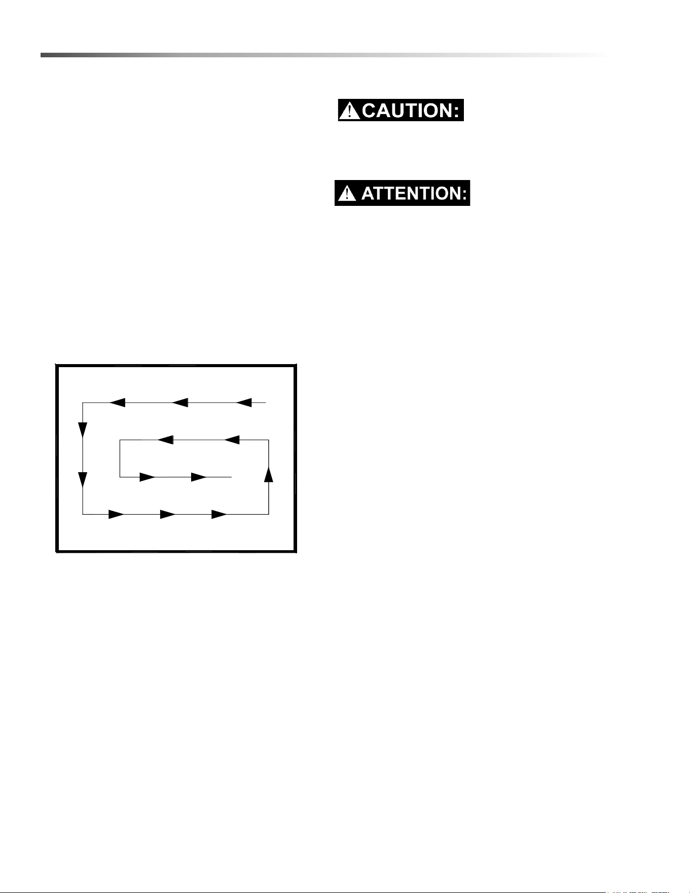
Normal Vacuuming
Plan the vacuuming pattern in advance. The longest
track is around the perimeter of the area to be cleaned.
For efficient operation, the runs should be the longest
possible without turning or stopping.
In order to achieve the best possible results, the area
which is to be cleaned should be picked up before
vacuuming. Large debris, strings and wire must be
removed to prevent being caught in brushes.
NOTE: Check and empty debris tray as needed
during operation.
If machine is allowed to stand in neutral with the
vacuum deck down for more than 2 seconds, the brush
motor stops. If either forward or reverse travel is
selected, the brush motor will continue once movement
of machine begins. Overlap the brush path and avoid
transporting over previously cleaned areas.
Recommended Path
To Begin Vacuuming
When operating the machine around people, pay
close attention for unexpected movement. Use
extra caution around children.
Lorsque vous utilisez la machine en présence de
gens, portez une attention particulière aux mouve-
ments inattendus. Soyez plus prudent, surtout en
présence d’enfants.
1. Stand on the operator platform. Throttle pedal must
not be depressed.
2. Turn key switch to turn machine power on.
3. Check position of Directional Control Switch to
ensure that machine is set to travel in direction
intended.
4. Rotate the Speed/Function Control Knob to one of
the two vacuum settings.
5. Drive machine forward to begin vacuuming.
6. Adjust the speed of the machine as necessary.
8.644-676.0 Operator’s Manual - iVac 24 ATV
21
Operations
To Stop Vacuuming
1. Remove foot from throttle pedal allowing pedal to
return to neutral.
2. Turn machine power off or switch to transport only
mode.
FOR SAFETY: Before leaving or servicing machine:
stop on level surface, turn off machine and remove key.
FOR SAFETY: When using machine, go slow on
inclines.
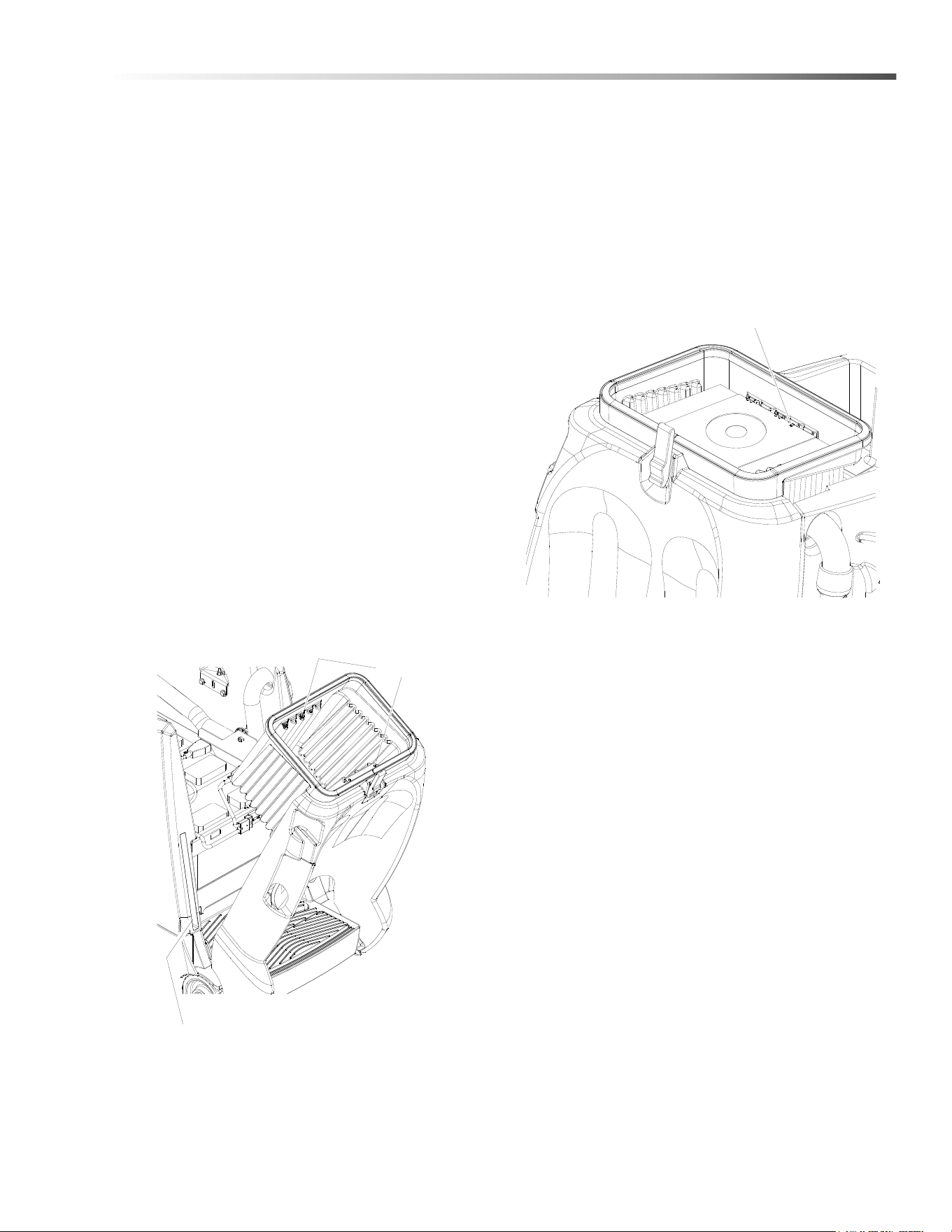
Changing Vacuum Bag
A convenient bag storage is built into side of machine.
1. Park machine on level area.
2. Turn the machine power off.
3. Unlatch and open top of machine.
4. Remove backing from vacuum bag’s sealing tag.
Seal top of bag.
5. Remove full vacuum bag from vacuum bag
housing.
6. Clean vacuum bag housing and remove any
debris.
7. Tilt back panel to retrieve a new clean paper bag
from the storage compartment in left side wall of
main cover.
8. Return back panel to operating position.
9. Unfold bag. There is a notch in cardboard on top of
bag. Align notch with housing front edge aligning
tab. Slightly bow cardboard to slide under
housing’s front and rear retaining tabs.
10. Close and latch machine top.
Retaining Clips
Vacuum Bag Storage Compartment
Vacuum Bag Housing Alignment Tab
8.644-676.0 Operator’s Manual - iVac 24 ATV

22
Maintenance
Service Schedule
MAINTENANCE
BEFORE
EACH
WORK
PERIOD
AFTER EACH
WORK
PERIOD
50 HRS
100
HRS
200
HRS
250
HRS
Check water level of batteries after
charging; add distilled water if necessary
*
Check that the vacuum box lid seal tightly *
Visually check for damaged or worn tires. *
Check vacuum hose connections. *
Check hoses for debris buildup. *
Empty debris tray *
Check pedal(s), brake and steering for
proper operation
*
Check vacuum bag fullness and change
if necessary.
*
Clean brushes and check wear. *
Remove bearing cap. Clean bearings
and cap.
*
Empty debris tray *
Charge batteries.
*
Clean off top of batteries. *
Check battery cells with hydrometer.
(Wet cell only)
*
Check battery connections are tight. *
Clean battery cases and compartment. *
Clean and check drive tension chain for
wear and tension.
*
Clean chains, cables and pulleys for
brush deck lift.
*
Check all motors for carbon brush wear. *
Check motor commutators. *
Check steering chain tensioner. *
Replace Filter *
8.644-676.0 Operator’s Manual - iVac 24 ATV
23
Maintenance
Batteries
1. Cover Retainer Latch
2. Rear Cover
3. Battery Connector-Machine
4. Batteries
5. Battery Tray
6. Batteries - Lithium Option
6
1
2
3
4
5
8.644-676.0 Operator’s Manual - iVac 24 ATV

24
Maintenance
Batteries (Wet Cell)
The batteries provide the power to operate the
machine. The batteries require regular maintenance to
keep them operating at peak efficiency.
The machine batteries will hold their charge for long
periods of time, but they can only be charged a certain
number of times. To get the greatest life from the
batteries, charge them when their charge level reaches
25% of a full charge. Use a hydrometer to check the
charge level.
Do not allow the batteries to remain in a discharged
condition for any length of time. Never expose a
discharged battery to temperatures below freezing.
Discharged batteries will freeze causing cracked
cases. Do not operate the machine if the batteries are
in poor condition or if they have a charge level below
25% (specific gravity below 1.155).
Keep all metallic objects off the top of the batteries, as
they may cause a short circuit. Replace worn or
damaged cables and terminals.
Check the electrolyte level in each battery cell before
and after charging the batteries. Never add acid to the
batteries, use distilled water. Do not allow water level to
fall below the battery plates. Portions of plates exposed
to air will be destroyed. Do not overfill. Keep plugs
firmly in place at all times.
Not all batteries require maintenance. AGM
batteries are maintenance free. Do not attempt to
remove sealed caps from AGM batteries. Warranty
is void if caps are removed from AGM battery.
L’entretien n’est pas nécessaire pour toutes les
batteries. Les batteries AGM ne nécessitent pas
d’entretien. N'essayez pas d'enlever les bouchons
scellés des batteries AGM. La garantie est annulée
si les bouchons sont retirés des batteries AGM
.
8.644-676.0 Operator’s Manual - iVac 24 ATV

25
Maintenance
When servicing machine, avoid contact with
battery acid.
Lors de l'entretien de la machine, évitez tout
contact avec l'acide de batterie.
Batteries emit hydrogen gas. Explosion or fire can
result. Keep sparks and open flame away. Keep
covers open when charging.
Les batteries émettent du gaz hydrogène. Une
explosion ou un incendie peut en résulter.
Maintenez les étincelles et les flammes nues à
l’écart. Gardez les carters ouverts lors du charge-
ment.
Wear eye protection and protective clothing when
working with batteries.
Portez des lunettes de protection et des vêtements
de protection lorsque vous travaillez avec des
batteries.
Charge batteries in a well ventilated area.
Chargez les batteries dans un endroit bien ventilé
Battery Maintenance
1. When cleaning the batteries, use a solution of
baking soda and water. Do not allow the cleaning
fluid to enter the battery cells, electrolyte will be
neutralized.
2. Maintain the proper electrolyte level in each battery
cell. If a cell should accidentally overflow, clean
immediately.
3. Wipe off the top of the batteries at least once a
week.
4. Test battery condition with a hydrometer at least
once a week.
5. Ensure that all connections are tight and all
corrosion removed.
6. Every 4 to 6 months, remove the batteries from the
machine and clean the battery cases and battery
compartment.
8.644-676.0 Operator’s Manual - iVac 24 ATV
26
Maintenance
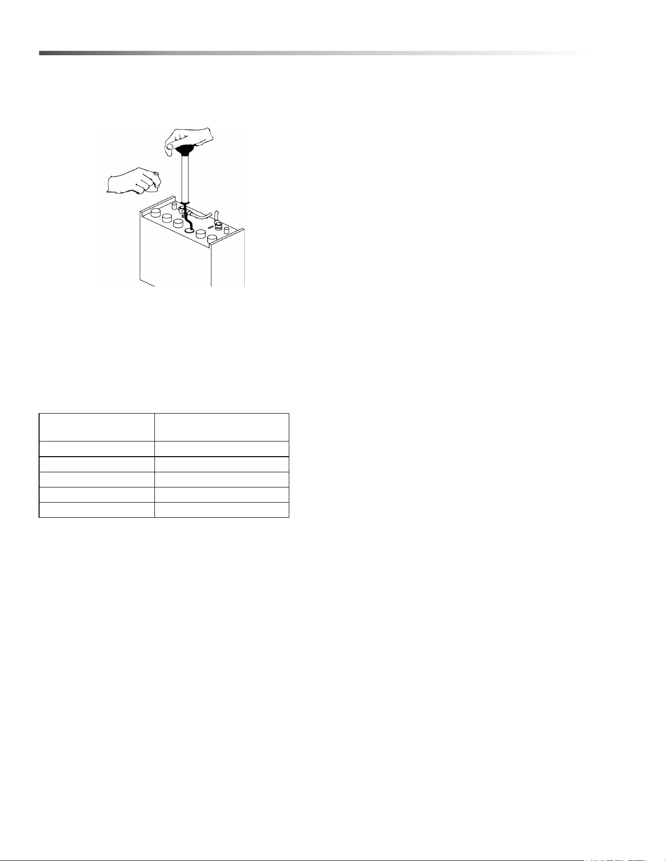
Checking Battery Specific Gravity
Use a hydrometer to check the battery specific gravity.
CHECKING GRAVITY
a. Hydrometer Battery
b. Battery
NOTE: Do not take readings immediately after adding
distilled water, if the water and acid are not thoroughly
mixed, the reading may not be accurate.
Check the hydrometer readings against this chart.
NOTE: If the readings are taken when the battery
electrolyte is any temperature other than 80°F (27°C),
the reading must be temperature corrected.
To find the corrected specific gravity reading when the
temperature of the battery electrolyte is other than 80°F
(27°C): Add (+) to the specific gravity reading 0.004 (4
points), for each 10°F (6°C) above 80° (27°C). Subtract
(-) from the specific reading 0.004 (4 points), for each
10°F (6°C) below 80°F (27°C).
SPECIFIC GRAVITY
@ 80° F (27°C) BATTERY CONDITION
1.265 100% CHARGED
1.225 75% CHARGED
1.190 50% CHARGED
1.155 25% CHARGED
1.120 DISCHARGED
8.644-676.0 Operator’s Manual - iVac 24 ATV
27
Maintenance
Charging Batteries
When servicing machine, avoid contact with
battery acid.
Lors de l'entretien de la machine, évitez tout
contact avec l'acide de batterie.
Batteries emit hydrogen gas. Explosion or fire can
result. Keep sparks and open flame away. Keep
covers open when charging.
Les batteries émettent du gaz hydrogène. Une
explosion ou un incendie peut en résulter.
Maintenez les étincelles et les flammes nues à
l’écart. Gardez les carters ouverts lors du charge-
ment.
Wear eye protection and protective clothing when
working with batteries.
Portez des lunettes de protection et des vêtements
de protection lorsque vous travaillez avec des
batteries.
Charge batteries in a well ventilated area.
Chargez les batteries dans un endroit bien ventilé
Use a 36 volt, 20 amp maximum output DC charger
which will automatically shut off when the batteries are
fully charged.
1. Stop the machine in a clean, well ventilated area
next to the charger.
2. Turn “OFF” machine.
FOR SAFETY: Before leaving or servicing machine;
stop on level surface, turn off machine and remove
key.
3. Remove rear cover, unplug batteries from
machine.
Batteries emit hydrogen gas. Explosion or fire can
result. Keep sparks and open flame away. Keep
covers open when charging.
Les batteries émettent du gaz hydrogène. Une
explosion ou un incendie peut en résulter.
Maintenez les étincelles et les flammes nues à
l’écart. Gardez les carters ouverts lors du charge-
ment.
4. Check the electrolyte level in each battery cell.
Before charging, add just enough distilled water to
cover the plates. After charging is complete, add
just enough distilled water to bring up the level to
the indicator ring. If the water level is too high
before charging, normal expansion rate of the elec-
trolyte may cause an overflow resulting in a loss of
battery acid balance and damage the machine.
8.644-676.0 Operator’s Manual - iVac 24 ATV
28
Maintenance
5. Replace the battery caps, and leave them in place
while charging.
6. Unplug the battery connector from the machine.
FOR SAFETY: When charging, connect the charger
to the batteries before connecting the charger to
the AC wall outlet. Never connect the charger to the
AC wall outlet first. Hazardous sparks may result.
7. Plug the charger connector into the battery
connector. Connect the charger AC plug to a wall
outlet. The charger gauge should indicate that the
batteries are charging.
8. When the batteries are fully charged, disconnect
the charger from the AC wall outlet, then discon-
nect the charger from the batteries.
9. Connect the batteries to the machine connector.
10. Check the electrolyte level. It should be up to the
indicator ring. If necessary, add distilled water.
11. Install the rear cover.
Changing Batteries
1. Stop the machine in a clean area next to the
charger. Turn off machine.
FOR SAFETY: Before leaving or servicing the
machine; stop on level surface, turn off machine
and remove key.
2. Open the console cover.
3. Tilt the rear cover back. The rear cover can also be
removed for better access.
4. If equipped with optional on board charger, tilt
charger mount to rear of machine.
5. Disconnect battery pack from machine.
6. Use the proper size open end wrench to discon-
nect main ground wire first and secure cable
terminal away from batteries.
7. Disconnect main positive lead and secure cable
terminals away from batteries.
8. Loosen both terminals on each jumper cable and
remove one at a time.
9. Prepare a suitable site to place the batteries.
Attach suitable battery lifting device and lift
batteries from the machine. Batteries are a
potential environmental hazard. Consult your
battery suppler for safe disposal methods.
Fixez le dispositif de levage de batterie approprié et
levez les batteries de la machine. Les batteries
constituent un danger potentiel pour l'environne-
ment. Consultez le fournisseur de votre batterie
pour connaître les méthodes d'élimination sûres.
RED
BLACK
RED
BLACK
RED
BLACK
REAR OF MACHINE
8.644-676.0 Operator’s Manual - iVac 24 ATV

29
Maintenance
Delta Q IC650 Charger Maintenance Instructions
1. Do not expose charger to oil, dirt, mud or direct heavy water spray when cleaning the vehicle or machine.
2. The enclosure of the charger meets IP66, making it dust-tight and protected against powerful water jets. The
AC inlet connection itself, when mated, is rated to IP20, which is not protected against water. Protect the AC
connection if used in wet or dusty environments.
3. If the detachable input power supply cord set is damaged, replace with a cord that is appropriate for your
region:
- North America: UL or CSA listed / approved detachable cord at least 1.8m in length (≥ 6 feet), 3 conductor,
16AWG minimum and rated SJT; terminated in a grounding type IEC 60320 C14 plug rated 250V, 13A
minimum.
- All other regions: Safety approved detachable cord, 3 conductor, 1.5mm² minimum, rated appropriately for
industrial use. The cord set must be terminated on one end with a grounding type input connector appropriate
for use in the country of destination and, on the other end, an output grounding type IEC 60320 C14 plug.
8.644-676.0 Operator’s Manual - iVac 24 ATV
30
Maintenance
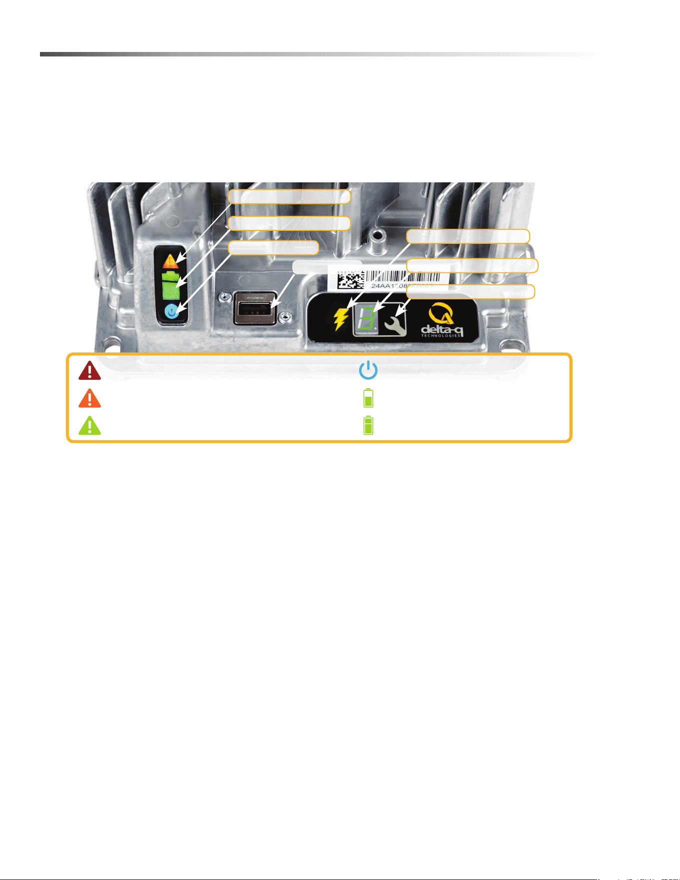
Delta Q IC650 Charger Operating Instructions
- The charger may become hot during charging. Use hand protection to safely handle the charger during
charging.
- Extension cords must be a 3-wire cord no longer than 30m (100') at 10 AWG or 7.5m (25') at 16 AWG, per UL
guidelines.
1. The USB Host Port allows data to be transferred to and from the charger using a standard USB flash drive,
including the downloading of charge tracking data and updating of the charger’s software and / or charge
profiles.
2. The Charging Output Indicator means that the charger output is active, and there is a potential risk of electric
shock.
3. The Charge Profile / Error Display shows one of four possible codes to indicate different conditions:
- ‘F’ codes meaning that an internal fault condition has caused charging to stop.
- ‘E’ codes meaning that an external error condition has caused charging to stop.
- ‘P’ code meaning that the charger programming mode is active.
- ‘USB’ code meaning that the USB interface is active, and the USB flash drive should not be removed.
The ‘E,’ ‘F’ and ‘P’ codes will appear, then are followed by three numbers and a period to indicate different
conditions (e.g. E-0-0-4). “See the Charger Fault Codes” or “Charger Error Codes” sections for details on
these conditions and their solutions.
4. The Select Charge Profile Button is used to select a charge profile from those stored on the charger. Up to 25
charge profiles can be stored. See the “Selecting A Charge Profile” section for instructions.
Fault / Error / USB Indicator
Battery Charging Indicator
AC Power Indicator
USB Host Port
1
Charging Output Indicator
2
3
4
Solid red = Charger fault
See display panel for details
Flashing amber = External error condition - caution
See display panel for details
Flashing green = USB port active
Solid green = Safe to remove USB ash drive
Flashing green = Low state of charge
Solid green = High state of charge
Flashing green = High state of charge
Solid green = charge completed
Solid blue = AC power available
Charge Prole/Error Display
Select Charge Prole Button
8.644-676.0 Operator’s Manual - iVac 24 ATV
31
Maintenance
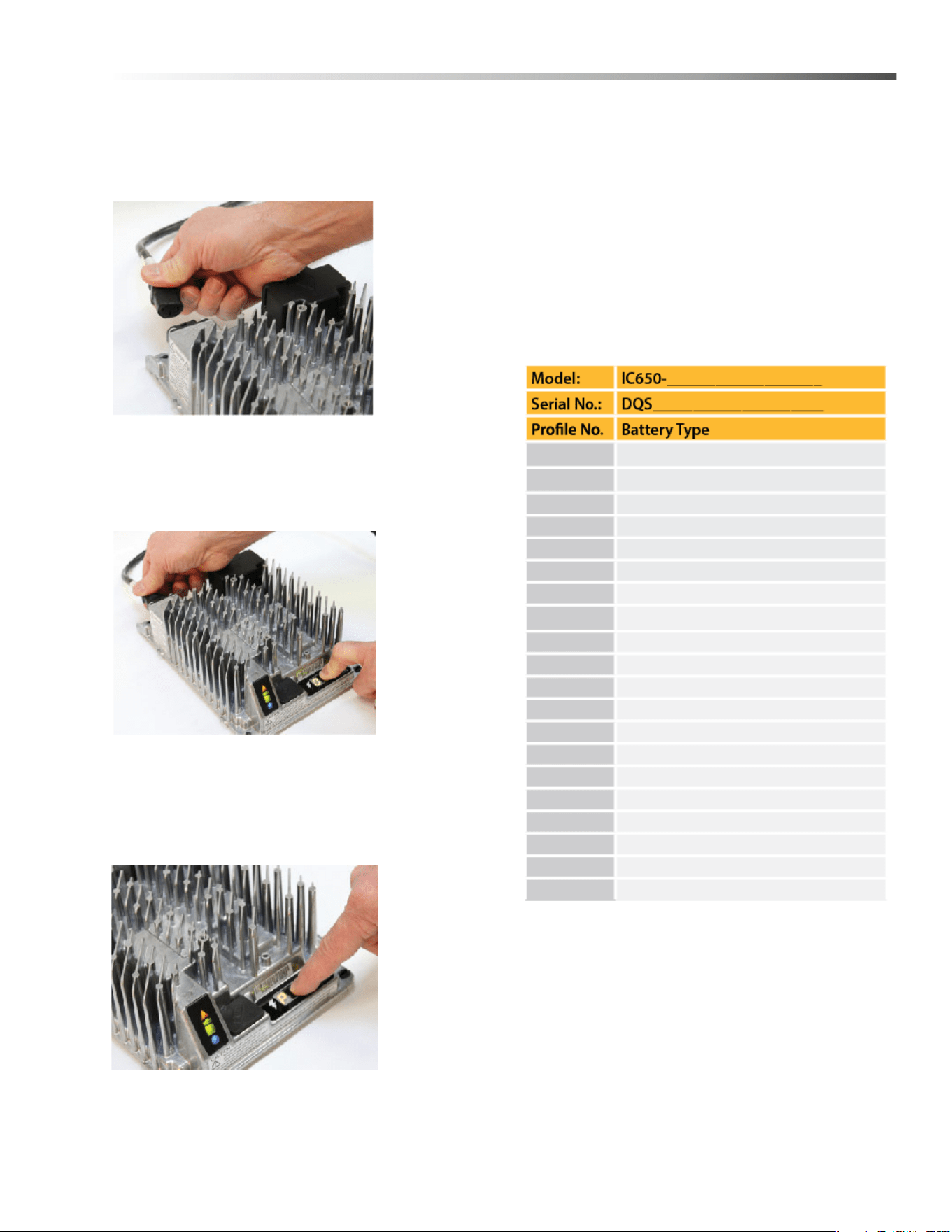
Selecting a Charge Profile
1. Disconnect AC input from the charger, or from the
wall outlet. Wait 30 seconds for the input relay to
open.
Figure 1:
Disconnect AC
input from the
charger.
2. While reconnecting AC input, press and hold
Select Charge Profile button. Hold the button until
Error Indicator is on and Battery Charging Indicator
starts flashing.
Figure 2:
Reconnect AC
input while
holding the
Select Charge
Profile Button.
3. Press and release the Select charger Profile
Button to advance through charging profiles loaded
on the charger. The selected charging profile will
be displayed up to three times (e.g. “P-0-1-1” for
Profile 11).*
Figure 3:
Press the
Select Charge
Profile Button
to advance
through the
charge
profiles. Hold
the button for
10 seconds to
confirm your
selection.
*Process will time out and profile will remain
unchanged if there is 15 seconds of inactivity, a profile
number is allowed to display three times, or if AC power
is cycled.
4. Once desired charging profile is displayed, press
and hold button for 10 seconds (see Figure 3) to
confirm selection and exit Profile Selection Mode.
5. Press the Select Charge Profile Button to check
that the desired profile is selected.
Use this table to record the charging profiles on
your charger.
Profile Logic
Profiles #42, 62 and 73 are programmed to automati-
cally restart a charge cycle after 14 days or 1.8V/cell
have been reached by the batteries if the charger
remains connected to AC power.
NOTE: Each profile is programmed to optimize the
life and performance of their corresponding battery,
contact the manufacturer before changing battery
charger profiles.
8.644-676.0 Operator’s Manual - iVac 24 ATV
32
Maintenance
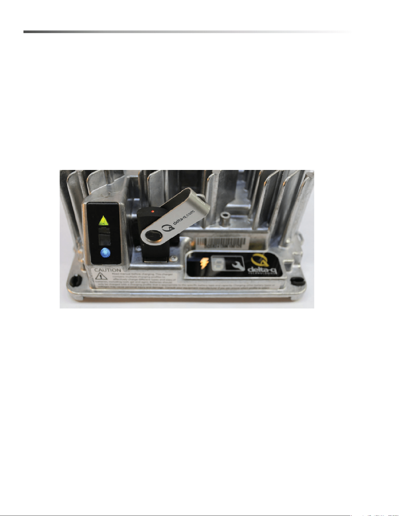
Configuring the IC650 Charger Using a USB Flash Drive
Using the Delta Q software, USB storage drives can be pre-programmed to certain charger configuration.
To use the USB port, follow these steps:
1. Insert the USB flash drive at any time, except during a charge cycle. Stop the charge cycle by removing AC
power or the DC connection to the batteries. The charger will power the USB port from the remaining AC
connection.
2. If there is enough disk space, the charger will write charge tracking data to the drive. The Fault/Error/USB
Indicator will flash green during reading and writing.
3. If the drive contains compatible configuration files, the charger will load them.
4. The IC650 Charger will briefly reset.
5. Remove the drive when the Fault/Error/USB Indicator is solid green.
Figure 4, Insert the USB flash drive to begin the reprogramming process. When complete, the Fault/Error/USB
Indicator will be solid green as shown.
Troubleshooting
If the alarm indicator flashes amber, note the error code and retry the update. If there is no response to inserting
the USB drive when the charger is being used off-board, check that AC power is available and connected. If the
charger is installed on-board, ensure that the charger either has AC power and / or batteries are connected.
Confirming a Software Update
After using a USB flash drive to update the charger firmware, the update can be confirmed by reviewing the .txt file
written to the flash drive by the charger. It will be located in the folder labelled ‘syslog’ (e.g.
F:\CHARGER\RESP\serialno\syslog\00000000.txt).
Open this file using a text editing program such as Notepad or Microsoft Word. If the update has been successful,
near the end of the text you will see a description resembling “SM Task: Successful upgrade at
Major[001].Minor[991].Build[000]variant[008].”
8.644-676.0 Operator’s Manual - iVac 24 ATV
33
Maintenance
Charge Tracking Data
All IC650 Chargers record data such as amp hours returned, charge cycle completion or interruption, and the
charge profile being used. This data can be very useful in vehicle or machine diagnostics.
To retrieve this data, follow these steps:
1. After a charge cycle is complete, or the charger is disconnected from the battery pack, insert a USB flash drive
with at least 2MB of free space into the IC650 Charger’s USB hose port. The charger will automatically begin
to download the data, shown on the Fault/Error/USB Indicator with a flashing green light.
If you plan to download data from a large number of chargers, having more free space on your USB flash drive is
recommended. If you want to update the software on only some of your chargers, it is recommended that you use
separate USB flash drives for updating and downloading charge tracking data.
Figure 5, Insert the USB flash drive to begin the charge data download process. This step can be completed using
the same USB flash drive programmed to update the charger’s software. The process is completed when the USB
indicator is solid green, and no longer flashing.
2. The downloading process is complete when the Fault/Error/USB Indicator is solid green. The USB flash drive
can be removed from the charger.
8.644-676.0 Operator’s Manual - iVac 24 ATV

34
Maintenance
Lithium Battery (Optional)
This product must be recycled and is made of recycled products
Chemical Risk
Lithium batteries are chemical risk if mis-operated, mishandled or abused.
Do:
• Do protect terminals from short circuit before, during, and after installation
• Do wear electrically insulated gloves
• Do use electrically insulated tools
• Do wear eye protection
• Do wear safety toe boots / shoes
• Do handle battery carefully
• Do secure battery safely
• Do always assume battery terminals are energized
Do Not:
• Do not lift or carry the battery during usage or operation
• Do not operate or store battery outside of operating limits
• Do not short circuit battery
• Do not puncture battery
• Do not expose battery to flames, or incinerate
• Do not open battery case or dissemble battery
• Do not wear rings, watches, bracelets or necklaces when handling or working near battery
• Do not drop or crush battery
• Do not lift battery by the terminal cables
• Do not vibrate battery
• Do not expose battery to water or other fluids
• Do not expose battery to direct sunlight
• Do not dispose of battery
• Do not connect with other types of batteries
• Do not expose battery to high temperatures
• Do not install with other battery types or brands
8.644-676.0 Operator’s Manual - iVac 24 ATV

35
Maintenance
Transportation
If the battery is not installed in equipment, it must be transported in the original package or equivalent.
Batteries are tested according to UN Handbook of Tests and Criteria, part III, sub section 38.3 (ST/SG/AC. 10/11/
Rev.5). For transport, the batteries belong to category UN3480, Class 9, Packaging Group II.
Operating Limits
The battery should not be operated outside these operating limits:
Opera
Do not install batteries in series. Select the appropriate AES battery model for the voltage of your system.
NOTE: Intentional bypassing of BMS to operate battery outside maximum and minimum limits voids warranty.
Fuse
Fuse provides back-up over-current protection.
Fuse Replacement
A blown fuse requires service from a qualified technician. Contact your Discover supplier for more information.
Operating Limits 12-36-6700
Continuous Charge Current 150A
Continuous Discharge Current 150A
Charge Voltage 40.8 V
Operating Voltage (Min / Max) 33.6 V / 43.8 V
Charge Temperature (Min / Max) 0°C / 45°C (32°F / 113°F)
Discharge Temperature (Min / Max) -20°C / 50°C (-4°F / 122°F)
Storage Temperature (Min / Max) -20°C / 45°C (-4°F / 113°F)
8.644-676.0 Operator’s Manual - iVac 24 ATV
36
Maintenance
Handling
Read Safety Section before installing the battery.
• Battery should be off.
• Battery cables should be disconnected.
• Battery terminals should be protected.
• Battery handle should be used to lift battery.
• Battery should be handled by two people or
mechanical lift equipment.
• Do not lift or carry the battery during usage or oper-
ation.
Installation - Single Battery
Read Safety Section before installing the battery.
Tools
• Insulated tools sized to match nuts, bolts and
cables in use
• Voltmeter
• Post cleaner and wire brush
• Personal protective equipment
Securing Battery
• Battery can be strapped in place with non-conduc-
tive nylon straps
• Battery may have hold down brackets at the base
of the battery
Installation
• Check that battery is switched off
• If battery circuit has disconnect, open disconnect to
isolate battery
• Clean cable connections. Broken, frayed, brittle,
kinked or cut cables should be replaced
• Install and secure new battery. Be careful not to
ground the terminals to any metal mounting,
fixture, or body part
• Connect battery cables. Connect ground cable
last to avoid sparks
• Recommended terminal torque is 9.0 Nm (6.64 ft-
lb)
• Close circuit disconnect (if open)
• Turn battery switch on
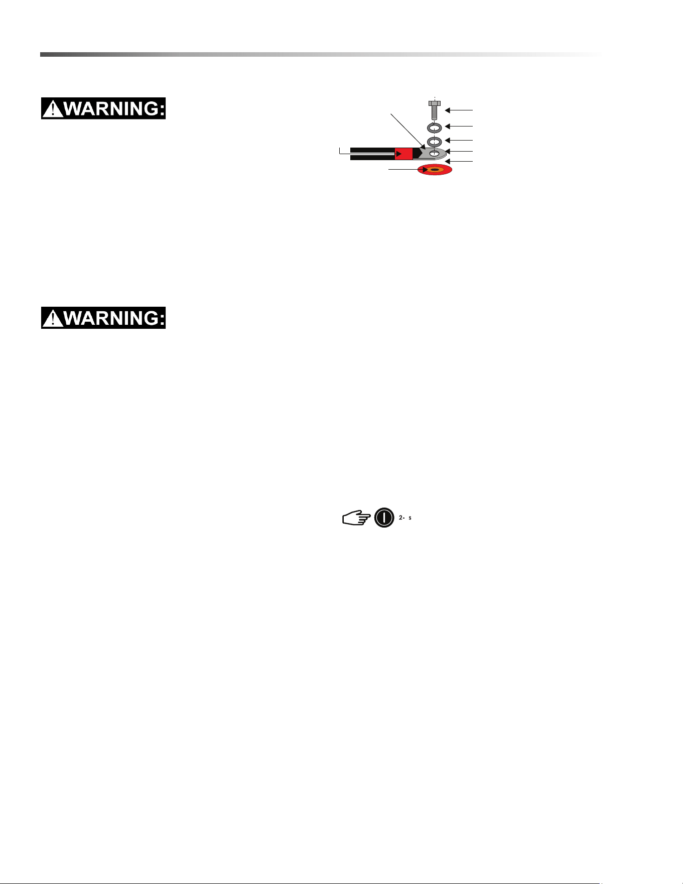
NOTE: All cable ends must be connected to battery
terminals without any washers between terminal
bushings and cable ends.
Terminal burnout is caused by:
• Discharge currents exceeding allowable limits
• Improper cable installation
• Improper cable sizing
• Improper terminal torque
NOTE: Without exception, product experiencing
terminal burnout will not be warranted.
Operation
NOTE: Review operating limits.
On–Off
• To turn the battery on press and hold switch for 2-3
seconds
• To turn the battery off press and hold switch for 2-3
seconds
M8” bolt (supplied with battery)
Copper compression lug
Shrink-wrap to
color-code the cable
Terminal surface
Lock washer (supplied with battery)
Flat washer (supplied with battery)
Battery cable lug
Ensure nothing is between
the terminal surface and the
battery cable lug
8.644-676.0 Operator’s Manual - iVac 24 ATV
37
Maintenance
Charging
Before operating the charger make sure to read and
understand the instructions that come with the charger.
Never attempt to charge a battery without first
reviewing and understanding the instructions for the
charger being used
Always make sure the chargers charging curve
meets the battery’s charging requirement; never
charge a visibly damaged battery; never charge a
frozen battery.
1. Connect the charger leads to the battery.
2. Make sure that the charger lead, both at the
charger and the battery side, connections are tight.
3. Turn the charger on.
4. Turn the battery on (if required).
NOT ALL CHARGERS ARE CAPABLE OF
CHARGING LITHIUM BATTERIES!
During system design CONFIRM that your chosen
charger is not capable of transient spikes that
exceed the published MAXIMUM TERMINAL
RATINGS of the battery.
Discharging
• Turn on battery.
• Turn on load
NOTE: Do not discharge battery below
recommended minimum operating voltages.
NOTE: Do not discharge battery at rates greater than
recommended operating currents.
Storage
Systems should be stored out of direct sunlight under
the following temperature conditions:
System should be put into storage at 80% SOC and
checked monthly to ensure the system SOC (state of
charge) does not fall below 20%/ At 2-% SOC the
battery will self discharge in approximately 2 months.
Protection & Faults
• BMS (battery management system) generates faults
when maximum operating limits are reached.
• BMS sounds a buzzer when fault limits are triggered.
• BMS monitors the following information for faults and
warning:
• Cell module voltage
• Battery current
• Battery temperature
Faults & Corrective Actions
In the event of a fault the BMS (battery management
system) will sound an audible buzzer warning and the
system will shut off after a 120 second delay.
Minimum Storage Temperature -20°C / -4°F
Maximum Storage Temperature 45°C / 113°F
FAULT LEVELS
Parameter Trigger Point
High Temperature 60°C / 140°F
High Voltage 3.7 V in any cell module
Low Voltage 2.5 V in any cell module
Over Current 150 A
8.644-676.0 Operator’s Manual - iVac 24 ATV

38
Maintenance
Service & Maintenance
Batteries should be carefully inspected on a regular
basis in order to detect and correct potential problems
before they can do harm. This routine should be started
when the batteries are first received.
Inspection
• Look for cracks in the case
• Check the battery, terminals and connections to
make sure they are clean, free of dirt, fluids and
corrosion
• All battery cables and their connections should
be tight, intact, and NOT broken or frayed
• Replace any damaged batteries
• Replace any damaged cables
• Check torque on terminal bolts
Troubleshooting
Battery Won’t Turn On:
CORRECTIVE ACTIONS
High Temperature
Stop discharge or charge
Leave the battery to cool
Low Temperature Stop discharge or charge
High Voltage If charging, stop charge
Low Voltage
Do not discharge the battery.
Any discharge current detected
will force the battery into Low
Voltage Fault
The user can charge the
battery in Low Voltage
Recovery
If no charge current is detected
within 2 minutes, the BMS will
turn off the battery
Over Current Reduce current
Low SOC
Stop discharge
Charge the battery
Symptom
Does the battery turn on for a short
time, then turn itself off?
Description
The battery is likely in a low voltage or
low SOC.
Action
Connect to charger and turn on the
battery.
Symptom
Was the battery left on or stored for
extended periods of time?
Description
The battery will turn itself off at 5%
SOC. If left sitting at a low SOC, the
battery may have discharged itself
completely and cannot be used.
Action Do not use. Replace and recycle.
8.644-676.0 Operator’s Manual - iVac 24 ATV

39
Maintenance
Changing Battery
Stop the machine in a clean area. Turn off machine.
FOR SAFETY: Before leaving or servicing the
machine; stop on level surface, turn off machine
and remove key.
1. Remove the rear cover.
2. Disconnect battery from machine.
3. Unlatch battery tray from machine and pull out to
expose battery.
4. Use the proper size open end wrench to discon-
nect main ground wire first and secure cable
terminal away from battery.
5. Disconnect main positive lead and secure cable
terminals away from battery.
6. Prepare a suitable site to place the battery.
Attach suitable battery lifting device and lift battery
from the machine. Batteries are a potential environ-
mental hazard. Consult your battery supplier for
safe disposal methods.
Recycling and Disposal
Batteries must not be mixed with domestic or industrial
waste. Discover’s Advanced Energy Systems are
recyclable and must be processed through a
recognized recycling agency or dealer. Please contact
Discover® or your servicing dealer for details.
8.644-676.0 Operator’s Manual - iVac 24 ATV
40
Maintenance
Circuit Protection
Circuit breakers interrupt the flow of power in the event of an electrical overload. When a circuit breaker is tripped,
reset it by pressing the exposed button. If a circuit breaker continues to trip, the cause of the electrical overload
should be found and corrected.
1.5 Amp. Protects the deck actuator.
18 Amp. Protects thebrush motor, 3 Amp fuse protects the side broom motor.
18 Amp. Protects the vacuum motor.
Circuit Breakers
3 A Fuse
8.644-676.0 Operator’s Manual - iVac 24 ATV
41
Maintenance
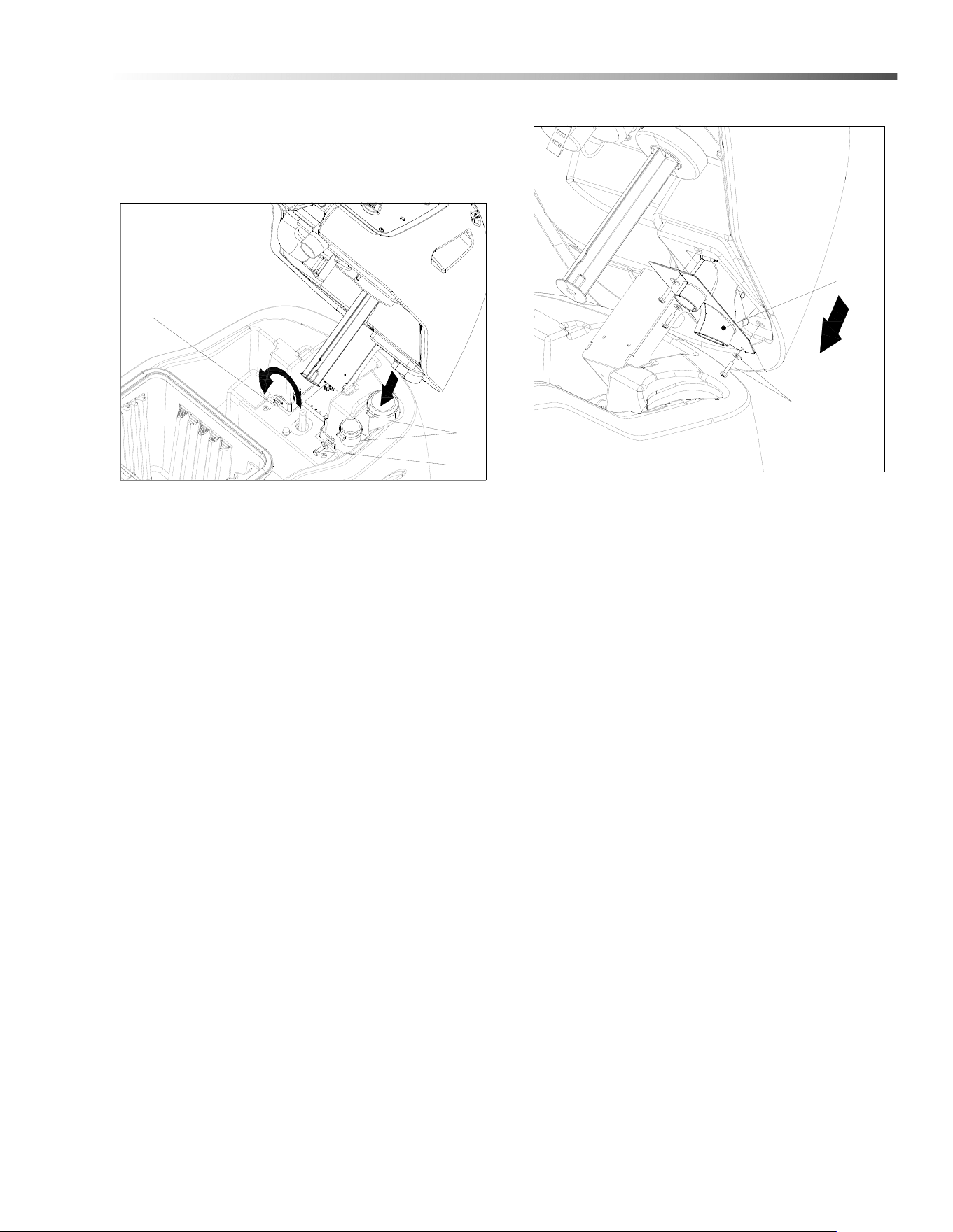
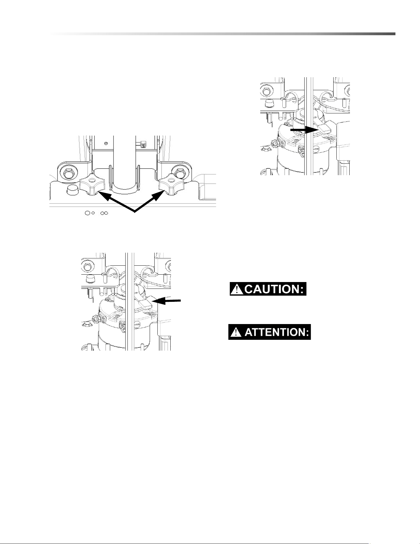
Vacuum Diverter Valve Maintenance
For maintenance and removal of the vacuum diverter
valve follow the steps below.
1. Remove hoses from diverter valve.
2. Remove screw and washer (1) on right side of
hinge bracket.
3. Loosen screw on left side to allow tank to rotate to
the left (do not remove screw). This will allow better
access for valve removal.
NOTE: Remove the post filter for easier access.
4. Remove the three (3) screws and washers
retaining the diverter valve assembly to the
console.
5. Gently pull valve assembly from console to avoid
damaging valve.
6. Reverse steps to re-install.
1
2
3
4
5
8.644-676.0 Operator’s Manual - iVac 24 ATV
42
Maintenance
Brush Deck
1. Debris Tray
2. Brush Deck Door
3. Side Broom
4. Deck Lift Actuator
1
23
4
8.644-676.0 Operator’s Manual - iVac 24 ATV
43
Maintenance
Brush Deck
The dual cylindrical head is designed to agitate the
carpet while vacuuming. The first brush pushes debris
backwards. The second brush, brushing forward picks
up debris and throws it into the debris tray.
NOTE: The brushes should wear evenly side to side.
Brushes should be replaced as a set when bristle
length wears to height of yellow PerformAlert™
bristles.
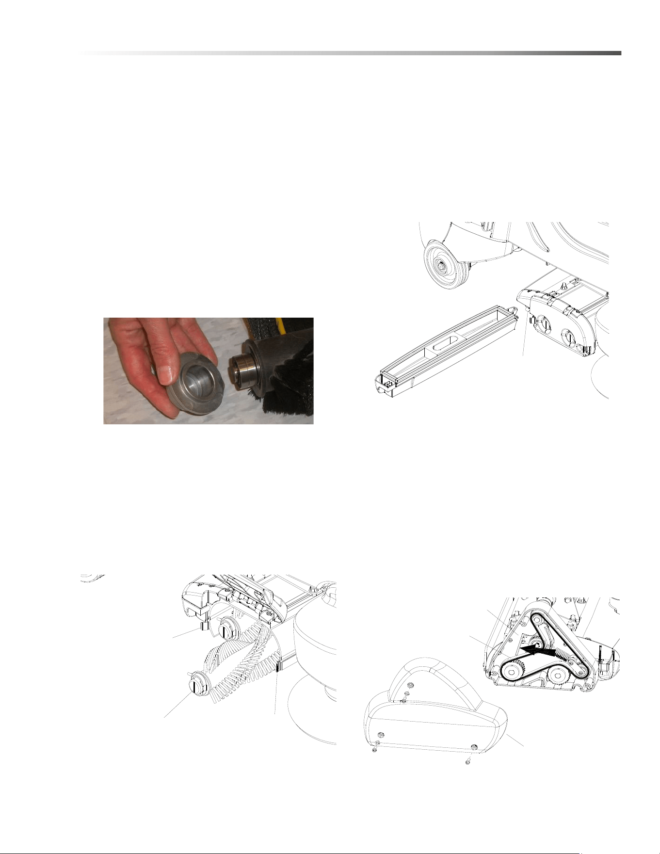
Brush Removal
The brushes are removed from the right side of the
machine.
1. Release door spring clips and raise the brush door.
2. Slide the brushes out the side opening. Remove
bearing cap. Clean bearings and cap.
Brush Installation
1. Slide brush through door opening and onto drive
shaft. Make sure it is fully seated and is driven by
the deck system.
2. Rotate the brush end caps until the indicator lines
on the ends are vertical.
3. Lower the brush door and secure with spring clips.
Debris Tray Removal
1. Release the debris tray spring clip.
2. Slide the debris tray away from machine.
Debris Tray Installation
1. Slide the debris tray into the debris tray mount
notch.
2. Secure with debris tray spring clip.
Belt Replacement
1. Remove three (3) cover screw and cover.
2. Push belt tensioner to the left as shown to release
belt tension. Remove belt and discard.
3. Thread new belt through pulley’s and tensioner.
4. Re-install cover.
NOTE: Belt must be installed with lettering facing out.
If installed incorrectly this may cause excessive noise
SPRING CLIP
VERTICAL INDICATOR LINE
SPRING CLIP
SPRING CLIP
COVER
BELT TENSIONER
BELT
8.644-676.0 Operator’s Manual - iVac 24 ATV

44
Maintenance
Do not use a pressure washer to clean around the
brush motors. Use tap pressure only.
N’utilisez pas de nettoyeur haute pression pour
nettoyer autour des moteurs des brosses. Utilisez
seulement la pression du robinet.
Remove Brush Deck
1. Lower brush deck.
2. Turn off machine
3. Disconnect motor harness connectors and remove
vacuum hose from top of deck.
4. Remove bumper bolts and bumper to access
linkage mount brackets.
5. Pull down and disconnect spring mount bracket
from deck lift arm. Keep spring attached to mount
bracket.
6. Remove four (4) bolts and associated hardware
that connect deck lift arm to linkage mount
brackets on drive assembly.
7. Remove two (2) bolts and associated hardware
that connect deck lift arm to lift linkage plate.
8. Pull out deck with attached deck lift arm.
9. Reverse to reassemble.
Replace Brush Deck Motor
1. Remove brush deck from machine.
2. Remove two (2) nuts to free rear mounting bracket
from deck.
3. Remove six (6) motor mount bracket face screws.
4. Remove rear mounting bracket.
5. Remove motor with attached coupler, leaving front
motor mounting bracket still attached to deck.
6. Remove coupler from old motor for reuse.
7. Inspect spider coupler for wear replace as needed.
Reverse process to reassemble with new motor.
Brush Motor Carbon Brush Replacement
1. Scribe alignment mark on motor barrel to motor
cap. Remove two bolts.
2. Remove end cap from motor.
NOTE: Motors contain two wave washers in cap. Do
not lose these.
3. Release brush from spring tension. Remove screw
connecting brush wire lead to brush holder. Clean
brush holder to insure free movement.
4. Retract spring and install new brush. Install
connector screw and lead.
5. When all new brushes are installed. Place all in
retracted position, held into brush holder by spring
tension.
6. Carefully place end cap onto bearing on motor
shaft.
NOTE: Use care to assure wave washer alignment.
7. With end cap in partially installed position, release
all brushes to contact position with motor commu-
tator.
NOTE: Failure to insure all brushes are released will
result in motor failure.
8. Reset end cap and realign with scribe marks on
motor barrel. Reinstall the two attach bolts from
cap into base.Maintain alignment between motor
barrel base and cap.
FOR SAFETY: before leaving or servicing machine,
stop on a level surface, turn off machine and discon-
nect powe
r.
Replacing Coupler Spider
1. Remove three (3) cover screws and drive housing
cover from end of brush deck.
2. Remove four (4) drive housing mounting screws
3. Slide out brush drive housing assembly with
attached coupler from end of brush deck extrusion.
4. Replace coupler spider.
5. Reverse to assemble.
NOTE: Align coupler jaws when sliding in brush drive
housing assembly.
8.644-676.0 Operator’s Manual - iVac 24 ATV
45
Maintenance
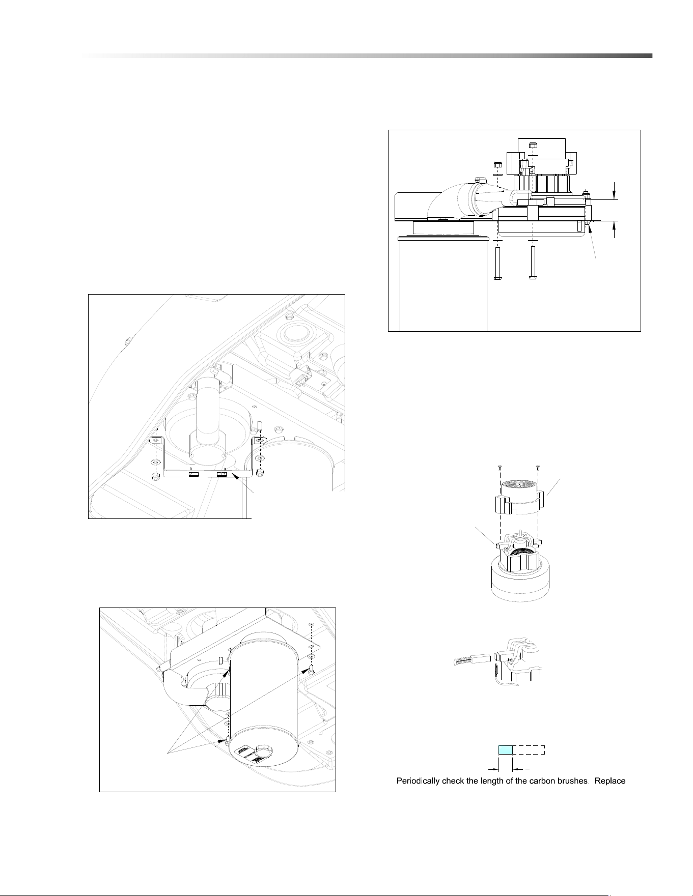
To Repair or Replace Vacuum Motor
1. Remove four (4) screws from top of control panel.
2. Tip control panel back from console to expose
vacuum motor wires.
3. Disconnect electrical connector from the vacuum
motor.
4. Replace one screw to secure control panel to
console.
5. Open console.
6. Remove the two (2) nuts from vac motor bracket,
as shown below.
7. Remove three (3) screws that secure vacuum
motor assembly in place. Remove vacuum motor
assembly, as shown below.
8. Remove move three (3) screws that secure
vacuum motor. Replace motor.
9. Reverse steps to install.
NOTE: If vacuum motor is not mounted as shown,
vacuum may not seal properly, resulting in poor
performance.
VACUUM MOTOR
BRACKET
VACUUM ASSEMBLY
MOUNTING SCREWS (3)
1.18
VACUUM MOUNTING
SCREWS (3)
3
8
[9.5mm]
Vacuum Motor Carbon Brushes
Carbon
Brushes
End Cap
If armature commutator is grooved, extremely pitted or not
concentric, the motor will need to be replaced or sent to a
qualified service center.
Inportant:
These brushes wear quicker as the length shortens due to
increased heat. Spring inside brush housing will damage
motor if brushes are allowed to wear away completely.
both carbon brushes when either is less tan 3/8" (9.5mm)
long.
8.644-676.0 Operator’s Manual - iVac 24 ATV

46
Maintenance
Drive Motor
Drive Motor Carbon Brush Replacement
Do not use a pressure washer to clean around the
brush motors. Use tap pressure only.
N’utilisez pas de nettoyeur haute pression pour
nettoyer autour des moteurs des brosses. Utilisez
seulement la pression du robinet.
FOR SAFETY: Before leaving or servicing machine,
stop on a level surface, turn off machine and remove
motor carbon brushes.
1. Open the console cover.
2. Tilt the rear panel back until it stops on the lanyard.
3. Grasp the lower end of the flexible steering shaft
and pull it straight up until it is disengaged with the
hex steering shaft.
4. Remove the cover and gasket at the steering shaft
area.
5. Grasp the drive wheel by reaching under the front
bumper and turn it to near the left steering stop.
6. The drive motor carbon brushes are located under
the metal band. Remove the band to access the 4
brushes.
7. Remove the phillips screw that holds each lead.
Remove the brushes.
8. Install the new brushes and reinstall the band.
9. Replace the gasket and cover, set the drive wheel
straight ahead, set the steering wheel straight
ahead, and gently align the steering shaft coupling
and slide onto the lower shaft.
10. Slowly close the cover and make sure the shaft
slides without binding.
Drive Chain Tension
The drive chain should deflect about 1/4 inch on either
side of the loop when the opposite side is tight.
To adjust chain tension:
1. Remove bumper.
2. Loosen the 1/4” nut behind the idler sprocket.
3. Tighten the front screw to increase chain tension.
4. re-tighten the 1/4” nut behind the idler.
5. Reinstall the bumper.
Transporting Machine
This machine is equipped with a drive gear engage-
ment/disengagement lever.
The brake automatically engages and keeps the
machine from moving whenever the operator stops the
machine.
The drive gear can be disengaged so the machine can
be pushed or towed (slowly).
When the drive gear is disengaged the machine cannot
be driven.
Lever access
Turn wheel to the right and remove internal cover plate.
8.644-676.0 Operator’s Manual - iVac 24 ATV
47
Maintenance
Brake Override
1. Disconnect battery to prevent injury.
2. Turn wheel slightly to the right.
3. Remove the knobs that hold the access panel in
place. Then remove the access panel.
NOTE: The access panel is located near the
batteries.)
4. Push the lever as indicated to disengage the
brake.
5. Push the machine slowly. Take care as voltage is
generated while pushing the machine and may
cause the controller to temporarily stop the
machine.
6. To re-engage the brake, push the lever as indi-
cated.
7. Reinstall the access panel and reconnect the
batteries.
Inclines
When navigating an incline the machine may come to a
stop. Turn the machine off. Wait 5 minutes and start the
machine and proceed up the incline.
Overheating may occur if you do not wait the full 5
minutes.
Une surchauffe peut se produire si vous n'attendez
pas les 5 minutes complètes.
Knobs
8.644-676.0 Operator’s Manual - iVac 24 ATV
48
Maintenance
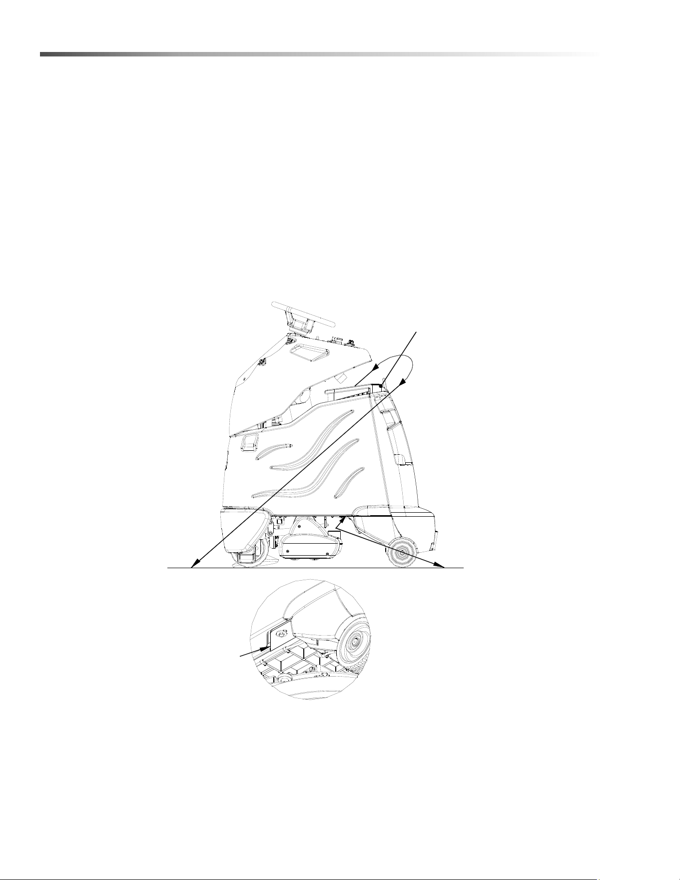
Preparation for Loading/Unloading Trailer
Before loading or unloading machine from trailer, brush deck must be in the up position.
When transporting the machine on a trailer or in a truck, in addition to using tie-downs, be sure to block the tires to
prevent the machine from rolling.
Machine Tie-Downs
There are two tie points located in front of the rear wheels on the frame, and a Tie-down wrap point on the vacuum
bag housing. Tie-down devices must be of the proper type and strength. The combined strength of all tie-downs
must be strong enough to lift two times the weight of the machine. Tie-downs must be positioned to prevent the
machine from moving forward, backward, or either side to side. Use all four corners of the machine with the tie-
downs running out opposite directions. Tie-downs must be attached to the transporting vehicle securely.
CONNECT
AT
FRAME
VIEW FROM
BOTTOM
Recommended Tie-Down Points
VACUUM
BAG HOUSING
8.644-676.0 Operator’s Manual - iVac 24 ATV

49
Maintenance
Troubleshooting
PROBLEM CAUSE SOLUTION
No machine function Console lid is open Close console lid
No power to machine Battery disconnected Check all battery cable connections
Emergency shut-off activated Reset
Battery cables corroded Clean connections
Faulty key switch Replace switch
Batteries not plugged in Plug batteries in
On Board charger plugged in Un-plug and stow cord
Little or no propel Low battery charge Charge batteries
Tripped circuit breaker Reset controller circuit breaker
Machine turned on with pedal not in neutral
position
Allow pedal to return to neutral. Restart
Controller protecting motor from overload
Controller limits motor amperage. Allow
unit to cool down for several minutes.
Machine is stalled against an obstacle
(threshold, curb, etc.)
Remove obstacle or push machine away
from obstacle
Controller overheated Allow cool down period
Loose motor connection
Check wires and connections from
controller to motor
Faulty throttle circuit or potentiometer
Check wires and connections from and
potentiometer resistance
Faulty drive reset circuit or switch Check wires, connection and switch
Faulty platform circuit or switch Check wires, connections and switch
Brake over-ride engaged Disengage brake over-ride
Faulty brake circuit or over-ride switch Check wires, connections and switch
Drive Lever disengaged Engage drive
Machine does not
change speeds
Faulty speed control circuit or switch Check wires & connections
Forward speed only
Reverse speed only
Faulty forward/reverse circuit Check wires & connections
Battery indicator light
flashing
Battery needs charged Charge Battery
Controller is indicating a fault code See fault code table
8.644-676.0 Operator’s Manual - iVac 24 ATV

50
Maintenance
Troubleshooting
PROBLEM CAUSE SOLUTION
Vacuum motor does not run, or
runs slowly
Faulty vacuum circuit or switch Check wires & connections
Worn vacuum motor brushes Replace brushes, check commutator
Vacuum circuit breaker tripped Reset circuit breaker
Vacuum and brush do not turn on Circuit breaker tripped Reset
Full bag or clog in system (bag full light
on)
Replace bag, empty debris tray, check
for and remove clogs
Poor vacuum performance Debris caught in system Remove debris
Low battery charge Charge batteries
Lid is not closed correctly Close and latch lid correctly
Faulty gaskets inspect and replace gaskets
Accessory hose is not sealed shut. assure hose is tight in hose holder
Bag or debris tray are full Empty tray, replace bag
Vacuum diverter valve not actuating Check for debris
Check electrical connections
Check timer circuit board
Brush motors do not run, or runs
slowly
Circuit breaker tripped Reset circuit beaker
Low battery charge Charge battery
Faulty brush circuit or motor Check wires, connections and motor
Bag full light on
Replace bag, empty debris tray or
remove clog.
Worn brush motor brushes
Replace brushes, check commutator
Deck won’t go down Actuator circuit breaker tripped Reset actuator circuit breaker
Side broom not running Fuse is blown
Clear foreign objects from broom that
inhibit free motion, replace fuse.
Brush door won’t close
Cylindrical brushes not installed
correctly.
Align brushes to drive shaft assem-
blies, close door.
8.644-676.0 Operator’s Manual - iVac 24 ATV

51
Maintenance
Battery Discharge Indicator Troubleshooting
The battery indicator flashes when a problem occurs. The table below list solutions for the indicated problems.
Number of
flashes
Problem Solution
1
The battery needs charging, there is a bad connection to
the battery or dependent on the programming, may
indicate that the battery lockout function is active and the
controller is in a restricted mode of operation. Check the
connections to the battery.
If the connections are good, try
charging the battery.
2
There is a bad connection to the drive motor. Check all connections between the
motor and the controller.
3
The drive motor has a short circuit to a battery connection. Contact your service agent.
4
The battery charge level has fallen below the battery
Lockout Level and the controller is inhibiting brush and
vacuum functions
Charge the battery.
5 Not used. -
6
The controller is being inhibited from driving, this may be
because the battery charger is connected (on board
charger only).
Disconnect battery charger.
7
A throttle fault is indicated. Make sure that the throttle is in the
rest position before switching on the
machine.
8
A controller fault is indicated. Make sure that all connections are
secure.
9
The parking brake has a bad connection. Check the parking brake and motor
connections. Make sure the
controller connections are secure.
10
An excessive voltage has been applied to the controller.
This is usually caused by a poor battery connection.
Check the battery connections.
- Blinks once every 5 seconds Sleep mode, cycle key switch
8.644-676.0 Operator’s Manual - iVac 24 ATV
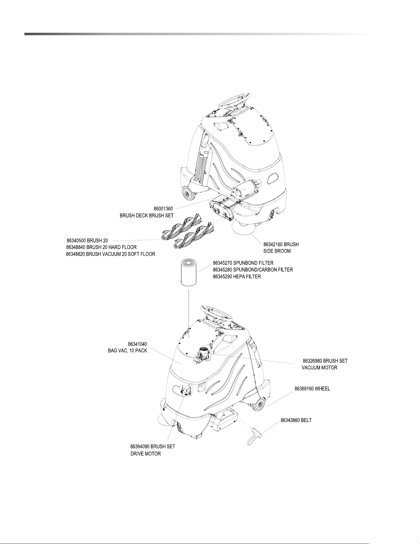
52
Suggested Spare Parts
8.644-676.0 Operator’s Manual - iVac 24 ATV

53
Notes
8.644-676.0 Operator’s Manual - iVac 24 ATV
Registrieren Sie Ihr Prudukt und Sie von vielen Vorteilen.
Register your product and benefit from many advantages.
Enregistrez votre produit et bénéficiez de nombreux avantages.
Registre su producto y aproveche de muchas ventajas.
Bewerten Sie Ihr Produkt und sagen Sie uns Ihre Meinung.
Rate your product and tell us your opinion.
Évaluez votre produit et donnez-nous votre opinion.
Reseña su producto y díganos su opinión.
www.kaercher.com/welcome
www.kaercher.com/dealersearch
Kärcher North America
6398 N Kärcher Way
Aurora, CO 80019
Phone: +1 800 444-7654
DANKE!
THANK YOU!
MERCI!
GRACIAS!
!
86446760 Operator Manual iVac 24 ATV