
DGL Group
2045 Lincoln Highway
Edison, NJ 08817
support@hover-1.com | hover-1.com
02
HOVER-1
PRO SERIES
DGL Group
2045 Lincoln Highway
Edison, NJ 08817, United States
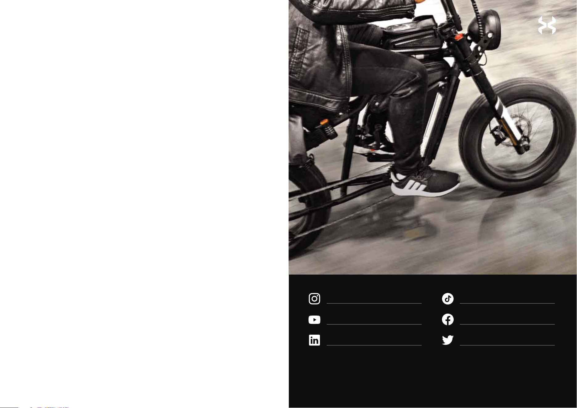
hover1rideables
hover-1
ridehover1
hover1rideables
@ridehover1
@ridehover1
Join our Hover−1 Community
of riders wherever you are!
support@hover-1.com
866.831.1520
www.hover-1.com
Thank you for choosing a Hover-1 Altai Pro. It is our pleasure to guide you
through setting up your Altai Pro and hitting the road!
Please read through this Owner’s Manual to get familiar with the proper
operation of your Altai Pro E-Bike’s controls, features, capabilities, and
limitations.
This manual will be your guide for general maintenance, safety precautions,
assembly, and servicing of the unit.
Before riding your Altai Pro E-Bike, be sure all the parts are properly torqued,
tightened, and connected (particularly the parts that had to be manually
installed). Remember to always use your best judgment and obey all traffic
laws.
Additional instructions and media will be available to assist you with repairs or
maintenance of your Hover-1 Pro Series E-Bike.
02
01
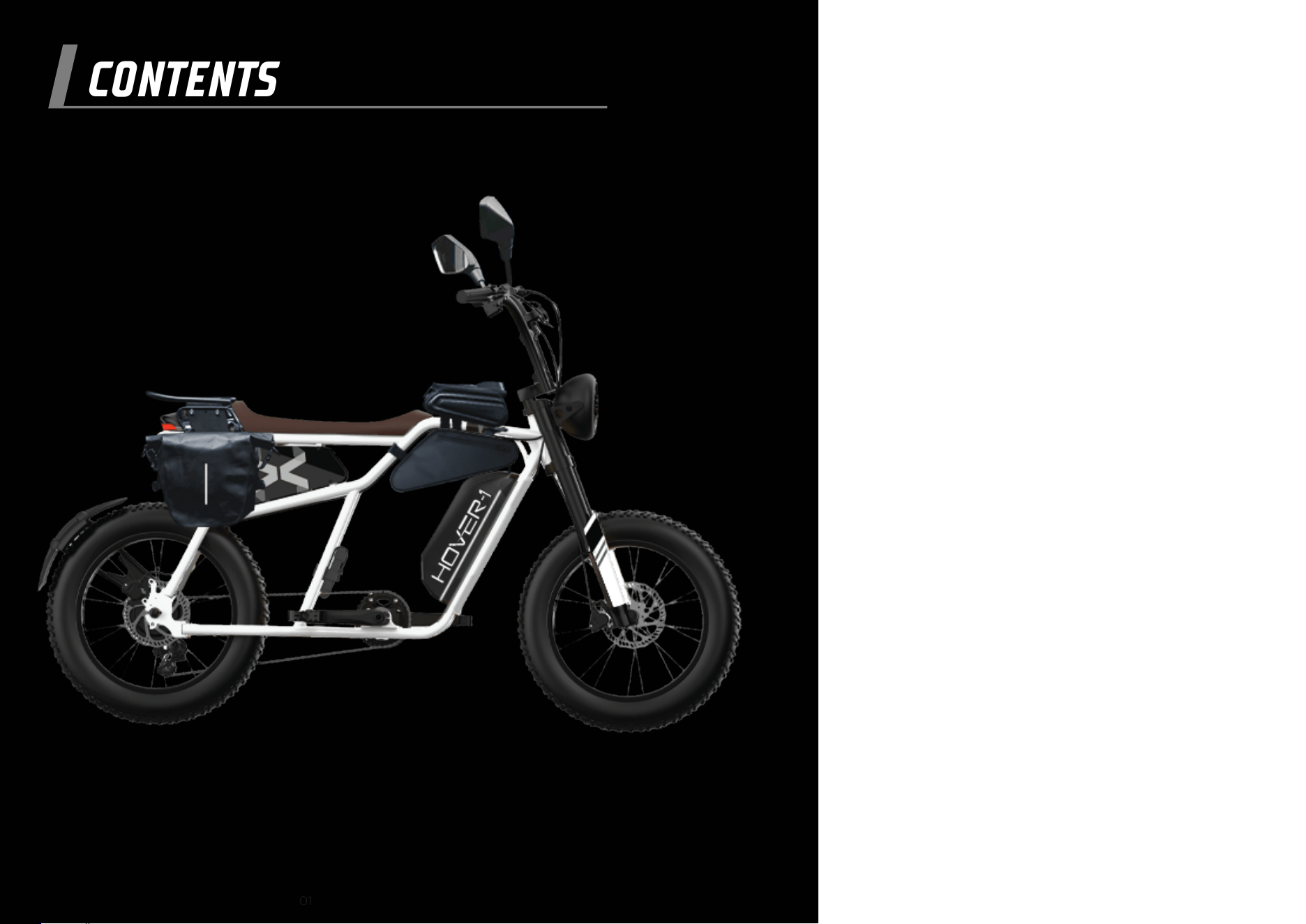
CONTENTS
01
50. WARRANTY
41. ALTAI PRO ACCESSORIES
05. BASICS
Diagram of the Altai Pro
General Symbols
Safety Advice
Legal Requirements
09. ASSEMBLY
Unpacking Instructions
Install the Handlebars
Connect the Display Cables
Install the Pedals
Prime the Brakes
Install the Rear Mudguard
Install the Battery Pack
Install the Front and Rear Reflectors
21. OPERATIONS
First Ride
Start Your E-Bike
Throttle
Pedal Assist Control
Cruise Control
USB Operation
Setting Menu
Light System
Suspension Fork Adjustment
Braking
Hover-1 E-Mobility App
Bluetooth Connectivity
Display Screen Information
Error Codes
35. MAINTENANCE
05
07
07
08
11
14
15
15
16
16
17
17
21
21
21
22
22
23
24
26
27
28
28
28
33
34
19. SAFETY CHECKLIST
03
04
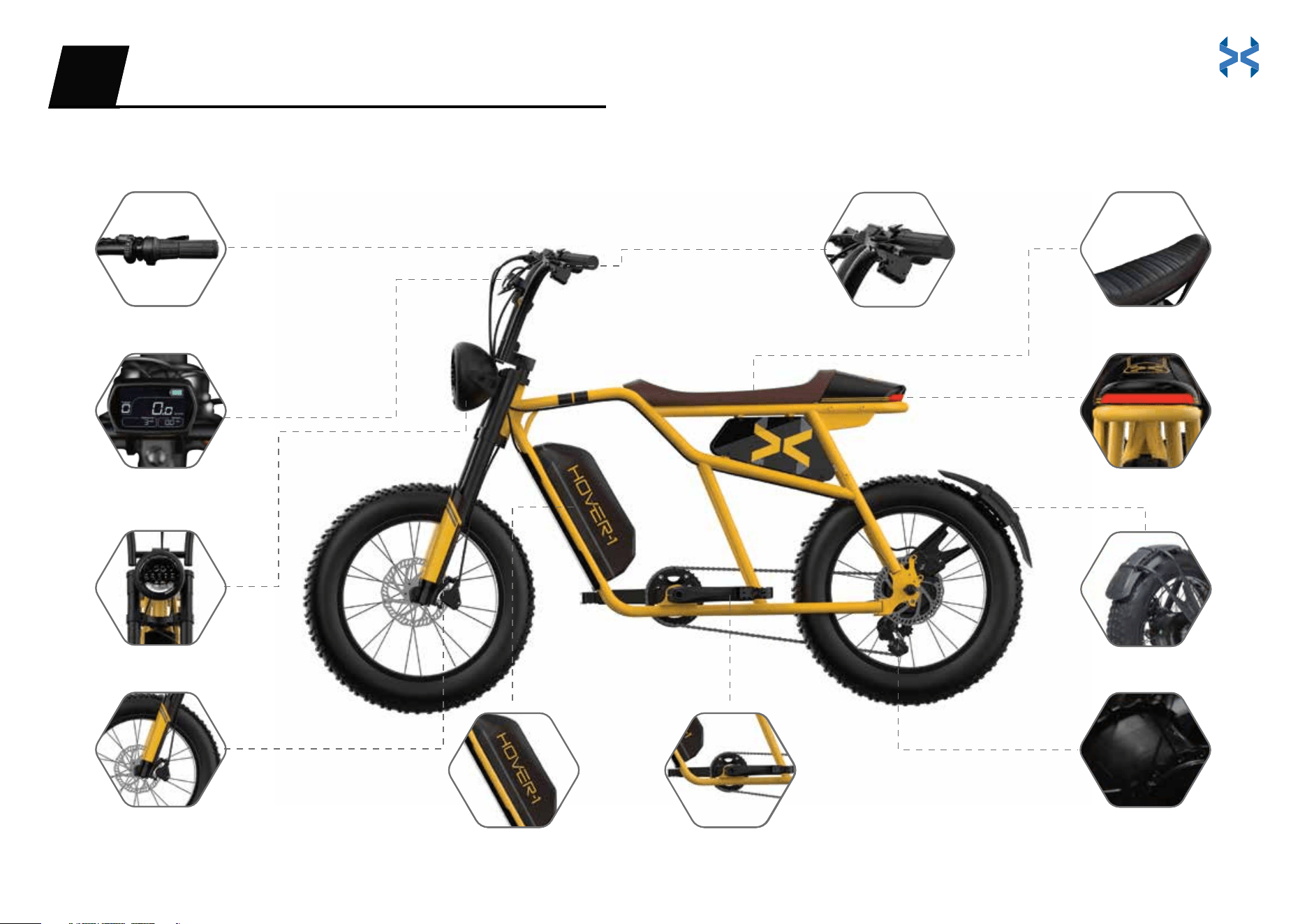
DIAGRAM OF THE ALTAI PRO
Twist Throttle
3.5” Full LCD Display
LED Headlight
Air Suspension Fork
Racing Seat
LED Taillight
Rear Mudguard
Hover-1 Pro Series Motor
BASICS01
Hydraulic Brakes
Removable Battery Crank Arm / Pedals
DIAGRAM OF THE ALTAI PRO
Twist Throttle
3.5” Full LCD Display
LED Headlight
Air Suspension Fork
Racing Seat
LED Taillight
Rear Mudguard
Hover-1 Pro Series Motor
BASICS01
Hydraulic Brakes
Removable Battery Crank Arm / Pedals
05 06

GENERAL SYMBOLS
SAFETY ADVICE
WARNING
WARNING
NOTICE
DANGER
Recommendations and meaningful additional information.
Warns about a situation that can cause death, serious physical injury and/or
heavy material damage if safety instructions are ignored.
Possible dangers to your life and health if respective calls to action are ignored.
Please adhere to the following safety instructions while operating your Altai Pro:
Always wear a properly fitted helmet and protective gear while riding.
See and be seen. Wear reflective clothing while riding at night.
Learn the rules of the road before riding. Obey all traffic laws.
Make sure handlebar grips are not damaged and are properly installed.
Always check brakes before riding.
Check for traffic. Always be aware of the traffic around you.
Watch for and avoid road hazards.
Reduce speed when riding on wet terrain.
To prevent skidding or potential injuries, do not accelerate or brake
suddenly while making turns.
To avoid water damage, do not leave your E-Bike in inclement weather.
When activating pedal assist, increase speed slowly to avoid injury.
Do not use and/or leave the charger outdoors in hot or wet weather conditions.
Do not ride up or down extremely steep inclines.
Do not touch the body of the motor immediately after riding,
as the surface may be hot.
Do not make any aftermarket modifications to your Altai Pro that
are not expressly approved by Hover-1 Pro Series.
Do not ride the E-Bike if you exceed the maximum weight limit of 264 lbs
.
Ride slowly in rainy and snowy weather and on slippery surfaces. Give yourself more
room to stop to ensure your safety. When braking on wet surfaces, use the rear brake
lever first, then the front brake lever.
Avoid the following hazards: drain grates, potholes, ruts,
soft road edges, gravel, and leaves, especially when they
are wet.
The rider must be able to straddle the E-Bike with at least
1 inch of clearance above the top tube when standing as
pictured.
This E-Bike is not designed for riders under 15 years old.
•
•
•
•
•
•
•
•
•
•
•
•
•
•
•
•
•
•
•
•
INSTRUCTIONS PERTAINING TO RISK OF FIRE OR ELECTRIC SHOCK -
IMPORTANT SAFETY INSTRUCTIONS
WARNING - When using this product, basic precautions should always be followed,
including the following:
Read all the instructions before using the product.
To reduce the risk of injury, close supervision is necessary when the product is used near
children.
Do not put fingers or hands into the product.
Do not use this product if the flexible power cord or output cable is frayed, has broken
insulation, or any other signs of damage.
This equipment is not intended to be used at ambient temperatures less than 0°C (32°F)
or above ambient temperatures of 30°C (86°F).
The battery is intended to be charged when the ambient temperature is between 0°C
(32°F) and 30°C (86°F). Never charge the battery when ambient temperatures are
outside this range.
Modifying or attempting to repair the E-Bike system except as indicated in the
instructions for use and care is prohibited.
Charging of the E-Bike shall only be performed with the manufacturer's recommended
charger.
SAVE THESE INSTRUCTIONS
07 08
WARNING
WARNING
DANGER
NOTICE
Tools Needed
ASSEMBLY02
Before performing any work on your Altai Pro, turn off the power system and
remove the battery. Be sure to also turn off the power system and remove the
battery when transporting your E-Bike in a vehicle (involuntary activation of the
electrical assistance system presents a risk of damage or injury).
• Do not open the box from the top, set the packaging box upright.
• A second person is recommended to help unpack and assemble your Altai Pro.
All riders of the E-Bike should follow these safety instructions.
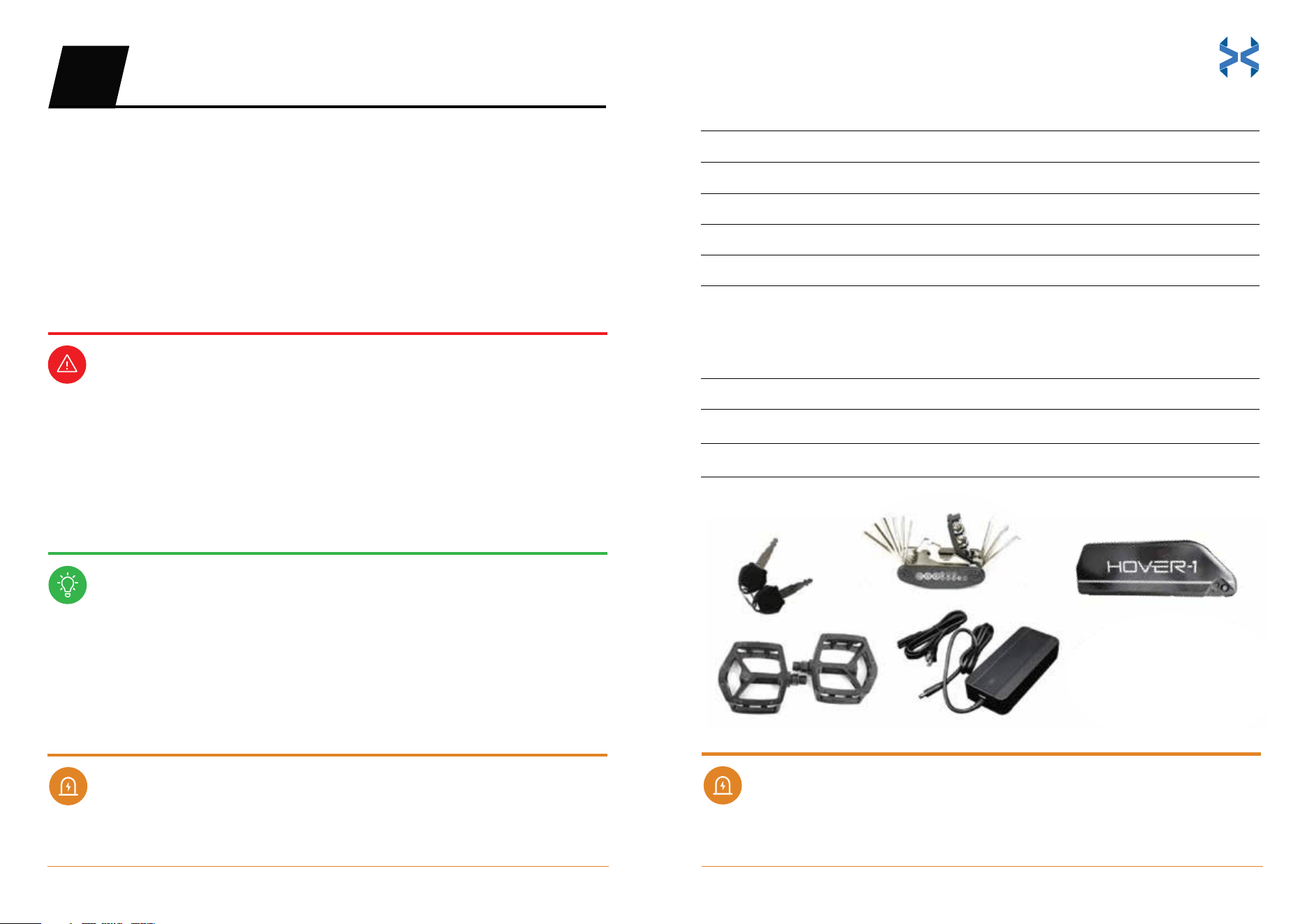
Assembly Parts:
Keys for the battery
Set of pedals
Battery charger
Battery
Handlebar assembly
Tool Kit:
Multi-tool
M6 Hex key (included in multi-tool) for handlebar assembly
M15 Wrench (included in multi-tool) for pedal assembly
Please read all assembly instructions in full before beginning to
build your new E-Bike.
Visually examine your shipping box and E-Bike to ensure that everything
arrived without shipping issues. Take pictures if you suspect rough handling and
contact: support@hover-1.com
If you require additional assistance, please reach out to support@hover-1.com
for more information. We often update user guides based on the feedback we
receive from our customers.
2
1
1
1
1
Quantity
1
1
1
Quantity
09 10
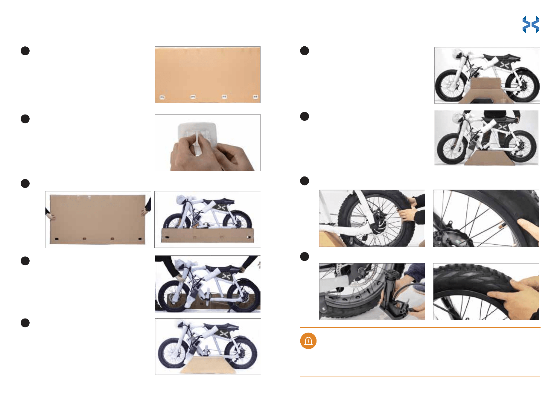
UNPACKING INSTRUCTIONS
Please exercise caution when
lifting the box, as it weighs about
73 lbs.
Remove the 4 plastic tabs at the
bottom of the package by
pinching and pulling them.
Remove the top lid of the box completely off the E-bike.
Remove the E-Bike and engage
the kickstand to stand the
E-Bike up.
Locate the parts box.
Take all parts and tools out of the
box. Please refer to the 'Tools
Needed' section to ensure that you
have all the necessary parts for
assembly.
Lift the E-Bike onto the parts
accessory box. Do not press the
chain onto the box.
WARNING
1
2
3
6
7
4
5
Pump the front & rear tires to 26-30 PSI.
Adjust the gap between the tire and the hub. Ensure there are no deviations.
Check the gap again between the tire and hub. Ensure there are no deviations.
Deviations between the tire and hub could lead to injury.
8
9
Always wear a properly fitted helmet and protective gear while riding.
See and be seen. Wear reflective clothing while riding at night.
Learn the rules of the road before riding. Obey all traffic laws.
Make sure handlebar grips are not damaged and are properly installed.
Always check brakes before riding.
Check for traffic. Always be aware of the traffic around you.
Watch for and avoid road hazards.
Reduce speed when riding on wet terrain.
To prevent skidding or potential injuries, do not accelerate or brake
suddenly while making turns.
To avoid water damage, do not leave your E-Bike in inclement weather.
When activating pedal assist, increase speed slowly to avoid injury.
Do not use and/or leave the charger outdoors in hot or wet weather conditions.
Do not ride up or down extremely steep inclines.
INSTRUCTIONS PERTAINING TO RISK OF FIRE OR ELECTRIC SHOCK -
IMPORTANT SAFETY INSTRUCTIONS
WARNING - When using this product, basic precautions should always be followed,
including the following:
Read all the instructions before using the product.
To reduce the risk of injury, close supervision is necessary when the product is used near
children.
Do not put fingers or hands into the product.
Do not use this product if the flexible power cord or output cable is frayed, has broken
insulation, or any other signs of damage.
This equipment is not intended to be used at ambient temperatures less than 0°C (32°F)
or above ambient temperatures of 30°C (86°F).
The battery is intended to be charged when the ambient temperature is between 0°C
(32°F) and 30°C (86°F). Never charge the battery when ambient temperatures are
outside this range.
Modifying or attempting to repair the E-Bike system except as indicated in the
instructions for use and care is prohibited.
Charging of the E-Bike shall only be performed with the manufacturer's recommended
charger.
SAVE THESE INSTRUCTIONS
11 12
Attach the handlebars to the E-Bike frame.
Position the handlebar plate over the center of handlebar grooves. The
edges of the plate should cover the grooves.
Use the hex key to tighten the hex screws. Start with the top left and
bottom right screws and tighten them halfway.
Remove all the wrapping
from each part.
Set the parts accessory box aside
and engage the kickstand to
stand the E-Bike up.
Properly inflate the tires between 26-30 PSI. Do not over-inflate the tires.
INSTALL THE HANDLEBARS
1
2
3
DANGER
1
2
3
4
DANGER
Tilt the handlebars forward or back to adjust their position to your riding
preference.
10
11
Tighten all screws completely.
Repeat step 4 for the top right and
bottom left screws.
5
6
13 14
NOTICE
Match the colored cables to the same-colored ports behind the display:
• 3 green cables
• 1 black cable
• 1 blue cable
• 1 black main cable
Do not over tighten the stem bolt. Over tightening the stem bolt
can damage the steering system and cause loss of control.
CONNECT THE DISPLAY CABLES
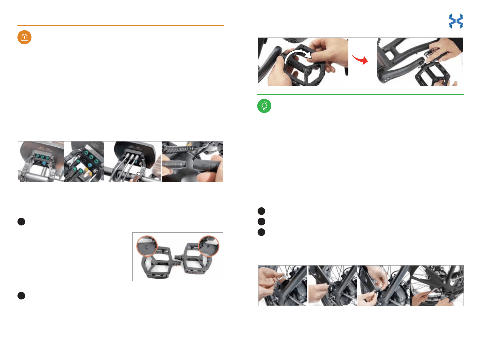
Identify the left and right markings on the pedals.
Install and tighten the pedals using the multi-tool. Ensure that
the right pedal is screwed on clockwise. Screw the left pedal on
counterclockwise.
• ‘L’ stands for the left pedal and
should be installed on the left crank
arm.
• ‘R’ stands for the right pedal and
should be installed on the right
crank arm.
INSTALL THE PEDALS
WARNING
1
2
PRIME THE BRAKES
Your E-Bike is equipped with hydraulic disc brakes. Squeeze the brake
handles 3-5 times to ensure optimal performance before your first ride
and after your E-Bike has been stored for an extended period of time.
It is always good practice to perform regular maintenance to ensure the E-Bike is in
proper working condition.
INSTALL THE REAR MUDGUARD
Find rear mudguard and locate the right side of rear tire for installation.
Match bolts with rear mudguard hole and loosely tighten the mudguard.
Use the multi-tool to tighten the rear mudguard completely.
Ensure it is tightened properly and does not move.
Check and re-tighten the pedals after each ride.
1
2
3
(Comes pre-installed. See instructions if reinstallation is needed)
15 16
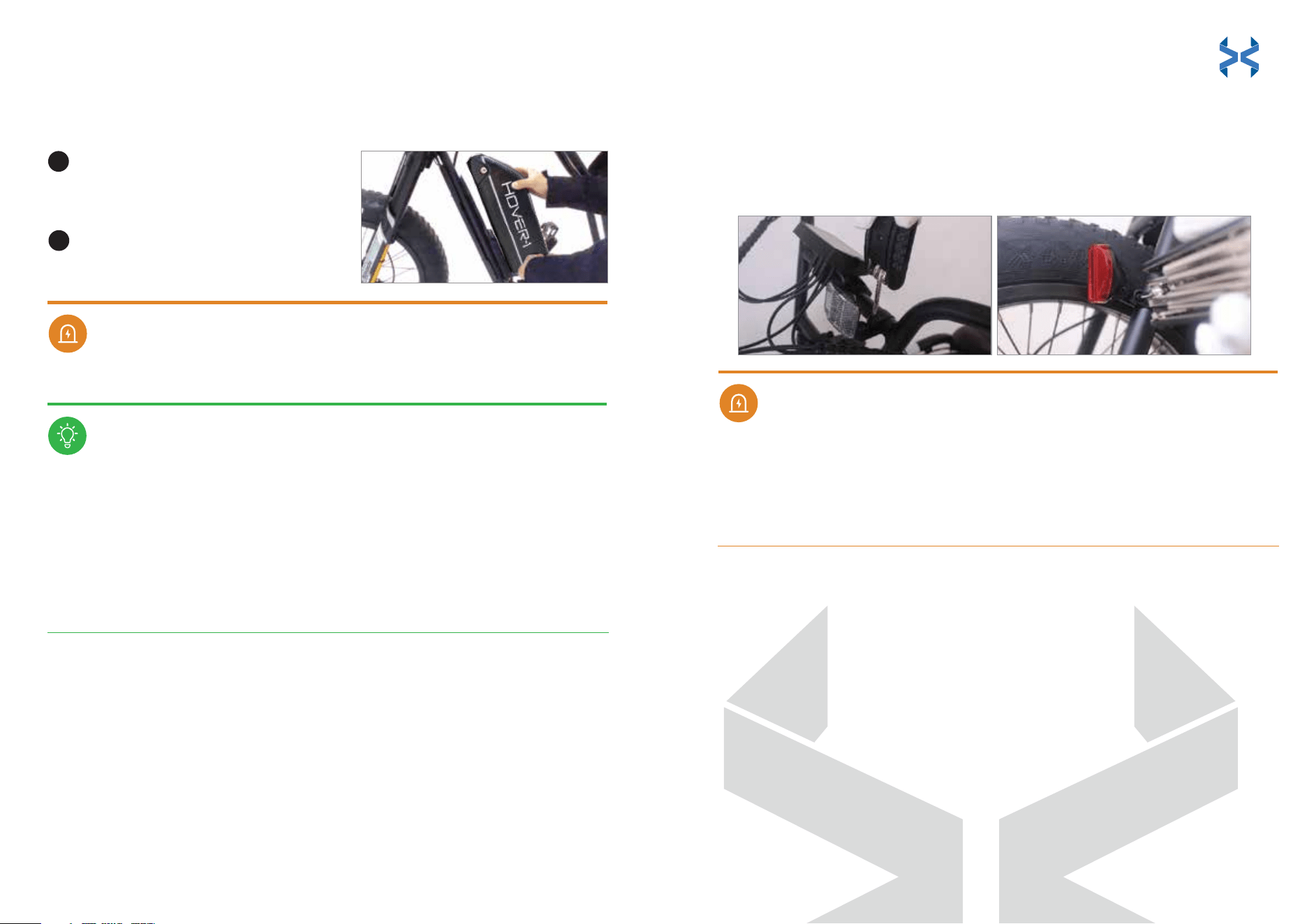
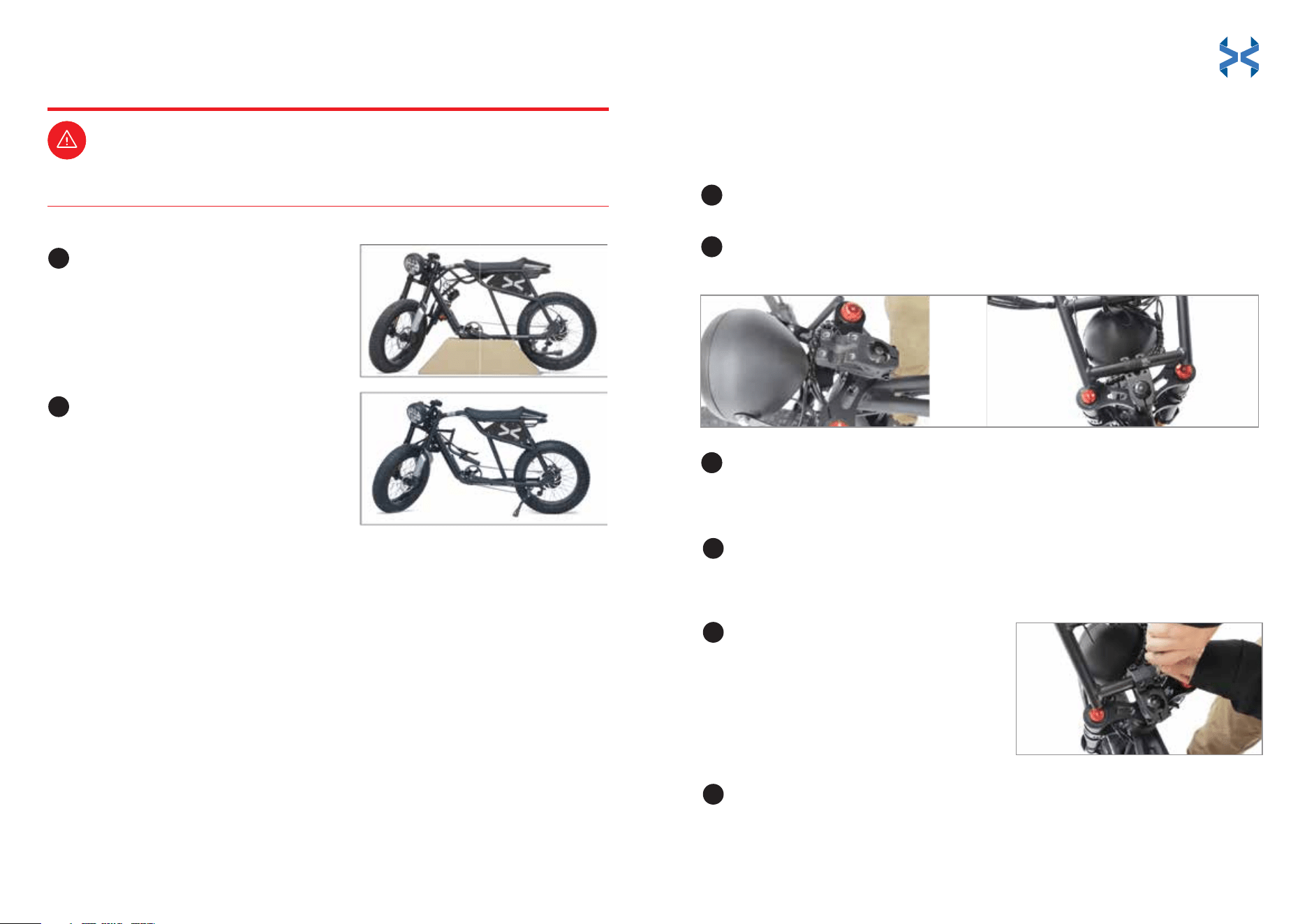
INSTALL THE BATTERY PACK
INSTALL THE FRONT AND REAR REFLECTORS
Match all the notched joints of the
battery to the E-Bike frame and slide
the battery into place.
Insert the key into the battery and
twist it clockwise to lock the battery
into place.
Remove the clamp screw from each reflector bracket. The front reflector is
white, and the rear reflector is red.
Push open the front reflector bracket loop and slide it onto the mid-section of
the handlebar assembly, next to the display. Align the reflector horizontally
(parallel to the ground), with the reflective piece facing the front of the E-Bike.
Clamp the front reflector to the handlebar assembly and completely tighten
the clamp’s screw with the multi-tool.
Push open the rear reflector bracket loop and slide it onto the E-Bike frame,
next to the rear tire. Align the reflector horizontally (parallel to the ground),
with the reflective piece facing the rear of the E-Bike.
Clamp the rear reflector to the E-Bike frame and completely tighten the
clamp’s screw with the multi-tool.
Before each ride, please ensure your E-Bike is safe to ride.
After assembly is complete, please proceed by:
1. Making sure that the headlight is pointing forward.
2. Making sure all the bolts on the E-Bike are properly
torqued, tightened, and connected.
3. Inflating the tires to 26-30 PSI. Excessive tire pressure could
rupture the tires.
WARNING
Be sure the reflectors are horizontally aligned and parallel to the ground. If the
reflectors are aligned vertically, aimed up, or aimed down, light may not
reflect properly, making you less visible to traffic. If the reflectors are not
horizontally aligned and/or parallel to the ground, loosen the clamp screws
and readjust them.
WARNING
NOTICE
1
2
1.
2.
4.
5.
3.
17 18

Please be sure all the items you installed are properly torqued, tightened, and
connected! If there any questions, please contact us: support@hover-1.com
Tire wear and tear depends on several factors, such as the weight of the rider
and type of terrain.
Follow battery charging and maintenance instructions.
Check that the battery is inserted securely.
Check that the battery is fully charged.
Pull both brake levers. You should feel an obvious pressure and the levers
should not be able to touch the handlebar.
4. Brakes system
Check if the headlight and taillight are working properly.
5. Lighting
Check for any loose cables.
6. Cables
Keep the chain lubricated and clean.
7. Chain
Check if the gears are shifting smoothly.
8. Gears
Check if your display turns on and functions properly.
9. Display
Check if the kickstand is tightly secure, not rubbing
against the ground or tires.
10. Kickstand
NOTICE
Do not cover any lighting fixtures or reflectors.
Do not sit on the E-Bike if the kickstand is engaged.
WARNING
NOTICE
NOTICE
NOTICE
NOTICE
SAFETY CHECKLIST03
3. Battery
4. Brakes system
5. Lighting
6. Cables
7. Chain
8. Gears
9. Display
10. Kickstand
NOTICE
WARNING
NOTICE
NOTICE
NOTICE
NOTICE
SAFETY CHECKLIST03
To be sure your E-Bike is safe on the road, please use the
following checklist before your first ride:
Check that the handlebars are tight by applying
the front brake and pushing the handlebars
forward and back.
1. Handlebars
Check the condition of the tires. Maintain proper tire pressure of 26-30
PSI. Check the tire treads for cracks, punctures, and deformations.
1. Handlebars
2. Tires
19 20
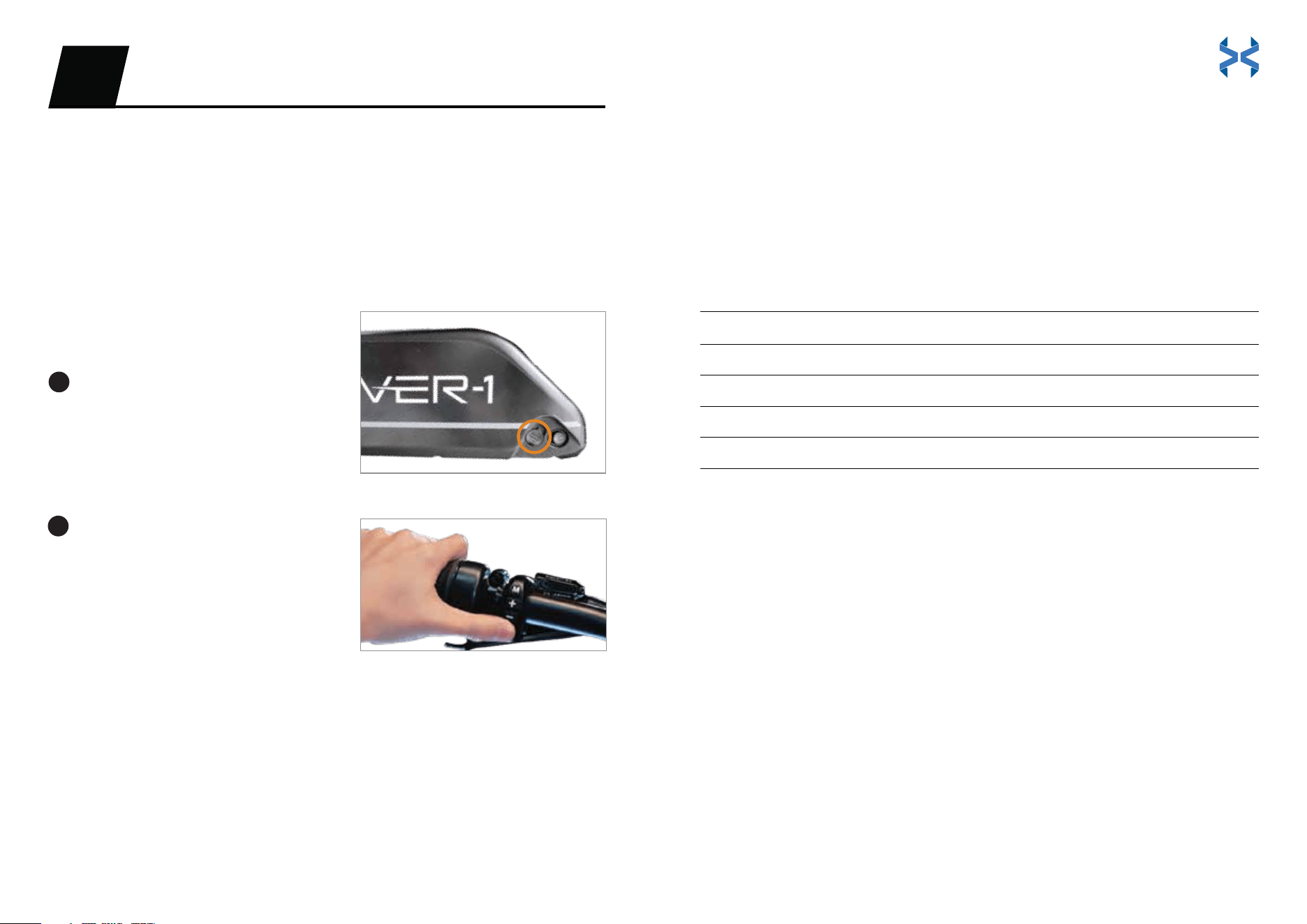
Press the button on the right side of
the battery.
‘-’ stands for on.
‘o’ stands for off.
Press and hold the power button on
the left side of the handlebar to turn
the unit on.
FIRST RIDE
OPERATIONS04
START YOUR E-BIKE
PEDAL ASSIST CONTROL
We recommend that you ride your E-Bike without using pedal assist at
first, to get familiar with the braking and gear shifting. Then, you can
start testing the pedal assist levels incrementally to determine the
optimal settings for your riding style.
Turn On the Altai Pro
Turn O the Altai Pro
Press and hold the power button.
Then, press the battery button to ‘o’. The E-Bike will shut off.
Pedal assist offers 5 levels.
THROTTLE
The throttle control is located on the right-side handlebar. Twist the throttle
toward you to activate it. Use the throttle and pedal assist at the same time or
either one individually. The Altai Pro E-Bike has a range of 35+ miles on a full
battery charge when exclusively using the throttle. Battery range results will vary
based on road conditions, temperature, rider weight, surface incline, and other
factors.
CRUISE CONTROL
Cruise control is set to ‘off’ by default. You must enable cruise control through
the E-Bike’s setting menu (refer to pages 24-25) or through the Hover-1
E-Mobility app. To initiate the cruise control function, maintain your speed for
at least 5 seconds. When you hear the beep, release the throttle and the
E-Bike will continue at the current speed. Apply the brakes or activate the
throttle again to cancel cruise control. Use caution when using cruise control
in areas of heavy traffic.
The LCD display will indicate the pedal assist level that you selected. Once you
start pedaling, the controller will engage the motor accordingly. The Altai Pro
E-Bike has a range of 85+ miles on a full battery charge when exclusively using
pedal assist level 1 and a range of 50+ miles when exclusively using pedal assist
level 5. Battery range results will vary based on road conditions, temperature,
rider weight, surface incline, and other factors.
Press ‘+’ to increase the pedal assist level.
Press ‘-‘ to decrease the pedal assist level.
The pedal assist levels are as follows:
Level 1
Level 2
Level 3
Level 4
Level 5
Level 0 O
Battery Eiciency
Tour
Medium
Sport
Super
1
2
21 22
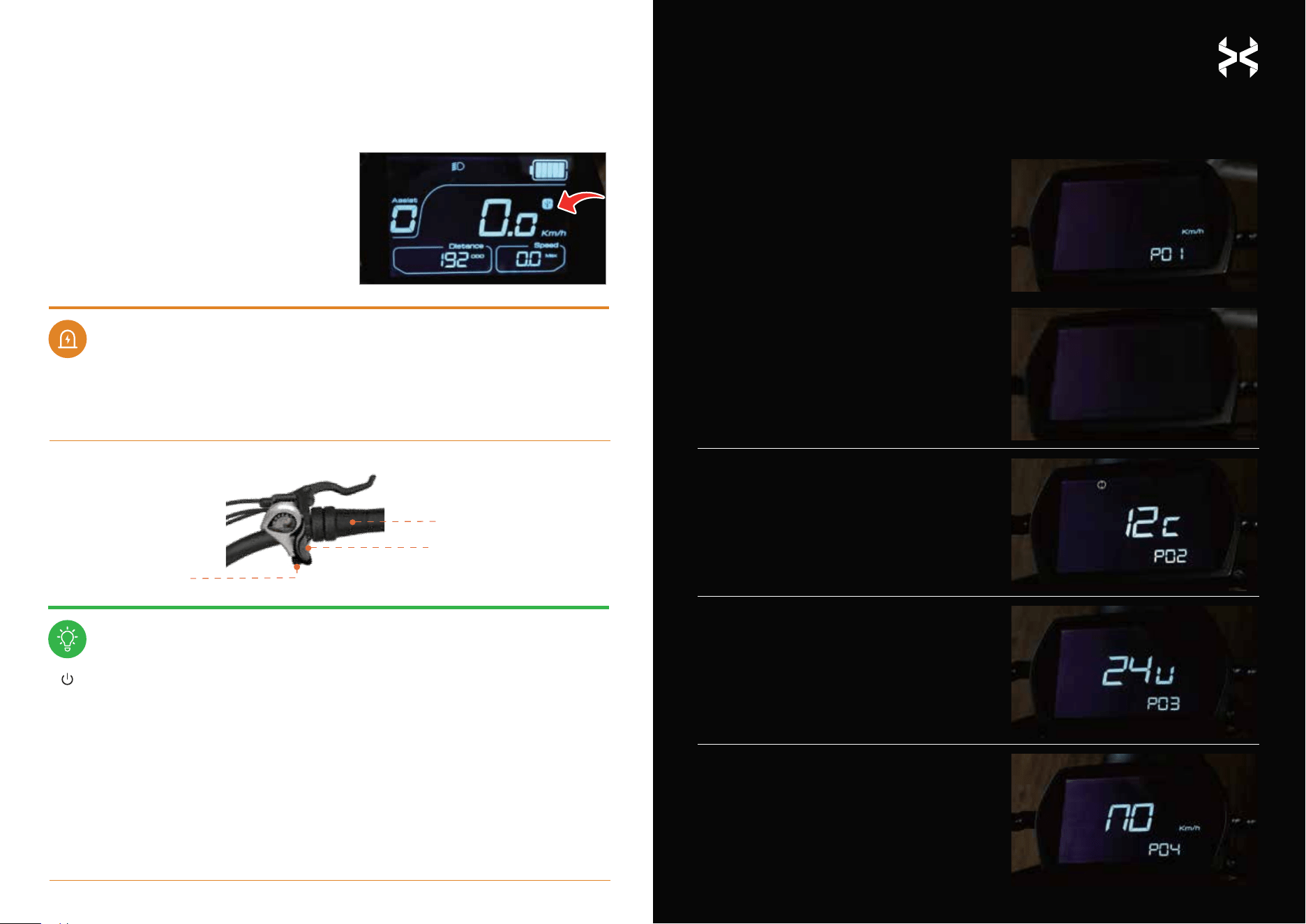
SETTING MENU
(Press & hold the ‘M’ button to access your E-Bike’s settings.
Quick-press the ‘M’ button to cycle through the available options)
USB OPERATION
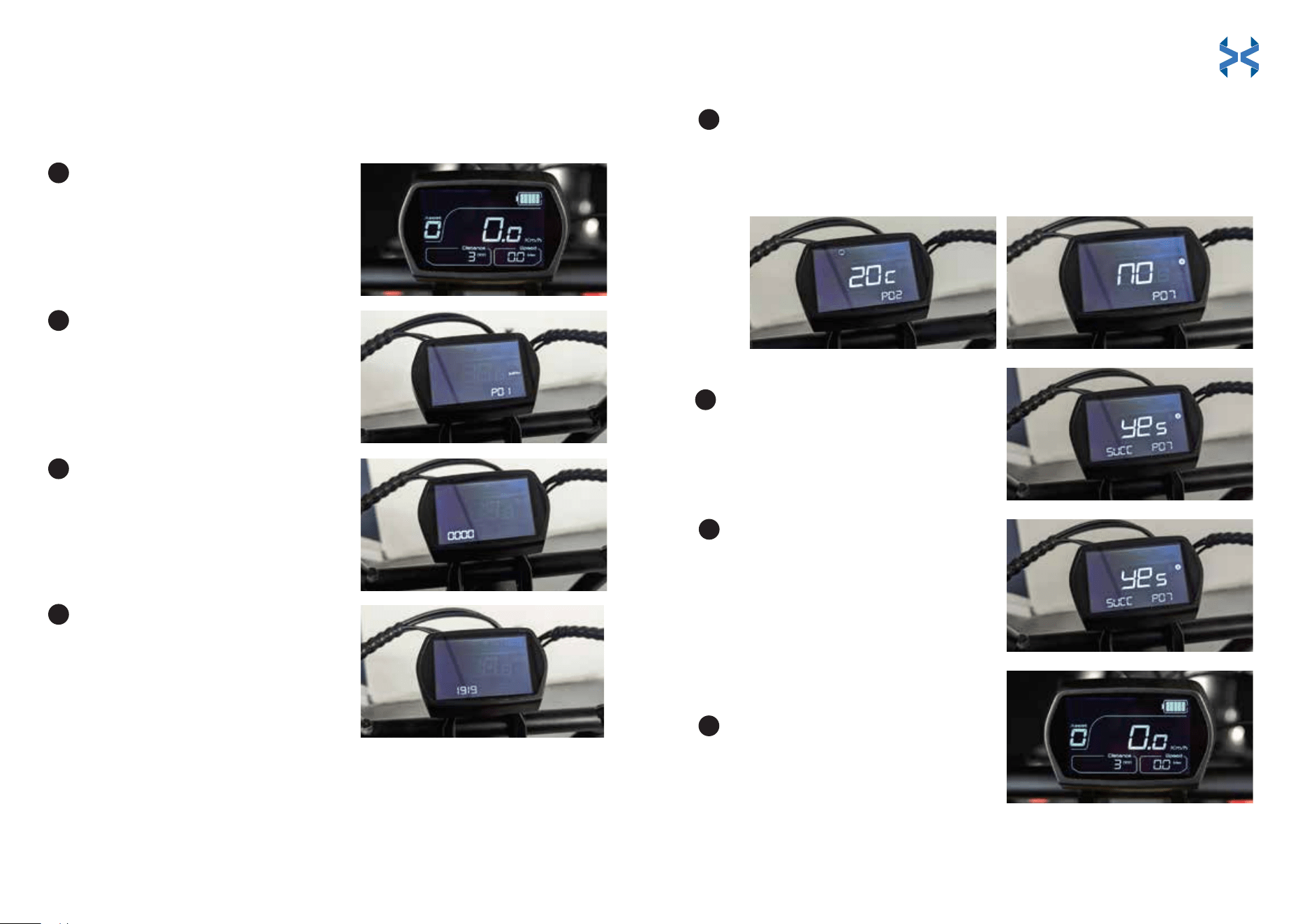
P01: Unit Setting
Press ‘+’ or ‘-’ to switch units
between km/h and mph.
When prompted for a password,
enter ‘1919’. Use the ‘+‘ and ‘-‘
buttons to cycle through the
numbers. Press the power
button to select a number, then
repeat for the remaining
numbers until finished.
Button: Power on and power off the E-Bike.
Button: Pedal assist level down.
Button: Pedal assist level up.
Button: Self-setting function button.
P02: Wheel Diameter Setting
Press ‘+’ or ‘-’ to switch the
figure from 12C to 28C
(FACTORY SETTING! DO NOT
TOUCH!).
P03: Rated Battery Voltage Setting
Press ‘+’ or ‘-’ to switch the voltage.
P04: Speed-Limiting Setting
Press ‘+’ or ‘-’ to switch speed modes.
You can switch to the following levels
of top speed: 6 km/h, 25 km/h, 32
km/h, 45 km/h (3.73 mph, 15.53 mph,
19.88 mph, 27.96 mph).
WARNING
NOTICE
;
Quickly press the ‘M’ button to get ‘USB’ to
show on the display. Then, open the USB
port located underneath the power button
to connect with your smartphone.
If an error indicator appears on the display, please check the error code list.
If you still require assistance, please contact customer support at:
support@hover-1.com
Gear Shift Down
Twist Throttle
Gear Shift Up
1919
-
+
M
23 24

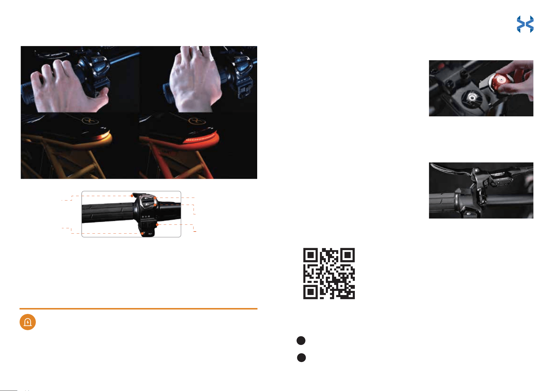
LIGHT SYSTEM
Click the L-shaped button above the high/low beam combo switch to turn the
headlight on. Click the button again to turn it off.
Turn On/O the Halo Light
Use the combo switch located on the left side of the handlebar and push the
switch up to activate the high beam light.
Turn On the High/Low Beam Light
Use the combo switch located on the left side of the handlebar and push the
switch down to activate the low beam light.
Turn O the High/Low Beam Light
Press the button with the horn icon located on the left side of the handlebar.
Horn Operation
The turning signals are operated from the left handlebar.
Turning Signals Operation
Press ‘+’ or ‘-’ to turn cruise control
on/off.
Use the combo switch located below the headlight button. Switching it to the
left will activate the left turn signal.
Turn on the left turning signal
Use the combo switch located below the headlight button. Switching it to the
right will activate the right turn signal.
Turn on the right turning signal
Use the combo switch located below the headlight buttons. Switching it to the
middle will turn off the turn signal.
Turn o the turning signal
P06: Pedal to Start Setting
Press ’+’ or ‘-’ to toggle pedal to start mode.
‘0’ will engage the motor without a pedal
start.
‘1’ will require a speed of 3 mph before pedal
assist or the throttle will engage.
P07: Bluetooth Reset
Press ‘+’ or ‘-’ to reset the Bluetooth
function.
‘no’ indicates you do not want to
reset the Bluetooth function.
‘yes’ indicates you would like to
proceed with resetting the Bluetooth
function.
P08: Software Version
To display the current
version of software.
P09: Display Version
To display the current
version of display.
P05: Cruise Control
25 26
SUSPENSION FORK ADJUSTMENT
Altai Pro is equipped with an inverted air suspension front fork and the ability to
adjust preload and rebound damping. In most cases, the standard setting for the
front fork will not require adjustment. But, if you desire a softer or stiffer ride,
adjust the fork as follows:
Adjusting the suspension can change the handling and braking
performance of your E-Bike. Test the suspension on hazard-free terrain
before doing so on the road. Continue to adjust your unit until you reach
your desired settings.
• Turning the compression dial
clockwise will increase pressure
on the suspension.
• Turning the compression dial
counterclockwise will decrease
pressure on the suspension.
Adjust the Fork
WARNING
Pairing Your E-Bike for the First Time
BRAKING
Altai Pro is equipped with front and rear hydraulic disc brakes. Brake sensors cut
power to the motor when either of the levers are compressed.
• The right lever will activate the rear
brakes when compressed.
• The left lever will activate the front
brakes when compressed.
Turn on your smartphone’s Bluetooth.
Open the Hover-1 E-Mobility App, search for the E-Bike, and connect.
1
2
Halo Light
Turn On/O
Horn Button
High Beam Button
Low Beam Button
Turning Signals
Halo Light
Turn On/O
Horn Button
High Beam Button
Low Beam Button
Turning Signals
BLUETOOTH CONNECTIVITY
HOVER-1 E-MOBILITY APP
Download the app to access
all of your Altai Pro E-Bike’s exciting features!
27 28
Press the power button to turn
the display on.
Press and hold the ‘M’ button until
the setting menu shows up on the
display (around 4 seconds).
Quickly press the ‘M’ button again
to activate the reset menu.
Press the ‘+’ or ‘-’ button to switch
the number from 0 to 9.
• The ‘+’ button will increase by
one number until it reaches 9.
• The ‘-’ button will decrease by
one number until it reaches 0.
When the first number has switched to 1, press the power to confirm
your selection. Then, enter the second number. Do this until the
password ‘1919’ has successfully been entered into the settings menu.
Continue pressing the ‘M’ button to cycle to P07
Quick-press ‘+’ or ‘-’ until ‘YES’ is
shown on the display.
1
5
6
2
3
4
Reset Instructions for Pairing a New Phone to Your E-Bike
(Read through all the steps before you begin)
Quickly press the power button
until ‘SUCC’ is displayed on the
screen (this stands for ‘reset
successful’). Now you can pair
the E-Bike to your smartphone.
The Bluetooth icon will display
once paired with a device.
Press and hold the ‘M’ button to
exit the setting menu and return
back to the main display.
7
8
Once the unit is switched to P07, press the power
button.
29 30

How to Unpair Your E-Bike
6 km/h = 3.73 mph
25 km/h = 15.53 mph
32 km/h = 19.88 mph
45 km/h = 27.96 mph
no = unrestricted
In North America
Limit Speed Through the App
In Europe
Open the Hover-1 E-Mobility App. Press and hold the E-Bike you want
to remove. Select ‘Remove device’ and click ‘Confirm’.
Each Altai Pro E-Bike comes programmed in speed restriction mode, which
allows for throttle operation and pedal assist up to 19.88 mph. This allows the Altai
Pro to be legally ridden on most bike paths without a license or insurance.
For areas where throttle-powered electric bicycles are not allowed, the Altai Pro
can be operated using pedal assist up to 28 mph.
Altai Pro follows EPAC (Electrically Power Assisted Cycles) operating standards
with pedal assist up to 25 km/h and 250 watts of power output (street legal for
all European countries).
Pedal assist up to 45 km/h is available only for private land use.
It is the rider’s responsibility to follow local E-Bike regulations. Be sure that you
are up to date with your local motor vehicle codes.
You can change the max speed of your Altai Pro E-Bike in the
Hover-1 E-Mobility app. Here are the top speeds of each speed
mode:
WARNING
Never adjust settings while in motion. Pull over and practice safe riding.
Simultaneously operating your E-Bike and using the app puts you at risk for
collision and serious injury.
LEGAL REQUIREMENTS
Please check your country or state’s regulations on electric bikes before riding.
There are variations on age limit, speed, motor wattage, and road accessibility.
Visit this website for more information:
https://peopleforbikes.org/our-work/E-Bikes/policies-and-laws/
In most European countries and Australia, the rules of public traffic pertaining
to bicycles also apply to E-Bikes traveling up to 25 km/h. However, there are
some notable differences (such as the age limit of the cyclist).
31 32

DISPLAY SCREEN INFORMATION
The main display presents several important metrics as follows:
ERROR CODES
The electronics system has the ability to self-diagnose and report a limited set of
errors. Errors will appear on the screen as error codes.
The chart below explains the meaning of each error code:
Maximum speed
Displays the max speed the E-Bike has
traveled. The speed can be shown in
mph or km/h.
Trip time/Trip distance
Displays the time and distance
the E-Bike has traveled until reset.
06
Motor Hall Signal
Abnormal
Check whether the connection of the
motor wire is short-circuited or loose.
07
Throttle Abnormal
Check the connection to the throttle. If
it is properly connected but showing
an error, replace the throttle.
ADVANCED MATRIX DISPLAY - ERROR CODE CHART
01
Controller
Communication Fault
Error Code Error Solution
Check whether the meter cable is
properly connected.
02
Controller Internal
Protection
Check whether the three-phase
power line is short-circuited.
03
Three-Phase Power
Abnormal
Check whether the three-phase
power line is loose.
04
Battery Under-voltage
Protection
Check if the battery should
be charged.
05
Brake Fault
Check the connection to the brakes. If
it is properly connected but displaying
an error, replace the brakes.
Battery level graphic
Representation of how much charge
remains in the battery.
Assist level
The current pedal assist mode the E-Bike is
in (the assist levels progress from 0 to 5).
Current power consumption
The current consumption of the E-Bike
battery.
Total distance
Displays how far the E-Bike has traveled
until the rider resets it. It is measured in
kilometers (km) or miles (mi).
Current speed
Displays the current speed that the E-Bike is
traveling. It is measured in mph or km/h
depending on your unit settings.
Average speed
Shows the average speed the E-Bike is
currently traveling. The speed can be
displayed in mph or km/h.
08 OR SC
Controller Fault
Check if the integrated cable is short
circuited. If so, replace the integrated
cable. If not, replace the controller.
33 34

TIRES
1. Frequently check the tire pressure, as all tires lose air slowly over time.
2. Do not use unregulated air hoses to inflate the tires/tubes.
3. Replace worn tires immediately.
It is recommended to do a maintenance check-up of your E-Bike at least once a
year. It is advised that the first maintenance check-up be performed after the first
155 miles/250 kilometers traveled or 3 months from receipt. Additional service is
recommended as necessary.
It is recommended that the battery be charged for about 7-8 hours prior to your
first use to help prime the lithium-ion battery cells for optimal performance.
Charge the Battery Pack
When charging the E-Bike, follow these steps.
When the charger is connected to the E-Bike, it will display a red light. When the
charging is finished, the indicator light will turn green. Put the rubber cap back on
the battery pack connector to ensure that it does not break while riding.
• Use only the charger supplied with the Altai Pro. Do not charge the
battery pack with any charger that is not supplied or approved to
charge the E-Bike.
• Do not cover the body of the charger while it is charging. Do not let
children charge the E-Bike without adult supervision.
• Do not leave the E-Bike unattended while charging.
• Do not use the charger in damp or wet locations.
• Do not drop the charger or subject it to strong vibration.
Ensure that the E-Bike is powered off.
Plug the charger into a 100-240V outlet.
Plug the charger into the E-Bike (the charger
connector can be found nearby the power
button on the battery pack).
Please read all instructions before charging. Failure to follow all
instructions listed below could result in death or serious injury.
The charger will be warm during charging.
• Do not use any charger that has been dropped. Do not short-circuit the
battery pack’s terminals.
• Do not overcharge the battery.
• Do not charge the battery pack while the temperature is over 140°F (60°C).
• Do not place the battery pack near fire or heat.
• Do not charge a frozen battery pack.
• Do not dispose of the battery in your trash. Please follow your local
municipality’s procedures for disposing of lithium-ion batteries.
WARNING
MAINTENANCE05
2
3
1
BATTERY
Remove the battery pack when storing or transporting the Altai Pro.
When removing the battery, follow these steps:
Removing Your Battery
Turn o the E-Bike.
Stand on the left side of the E-Bike. Locate the keyhole on the
E-Bike near the top of the battery pack.
Insert the key into the battery pack lock keyhole.
Turn the key counterclockwise and hold.
Pull the upper portion of the battery pack toward you.
Pivot the battery pack sideways and lift it away from the E-Bike.
2
3
4
5
6
1
35 36

• Use only the charger supplied with the Altai Pro. Do not charge the
battery pack with any charger that is not supplied or approved to
charge the E-Bike.
• Do not cover the body of the charger while it is charging. Do not let
children charge the E-Bike without adult supervision.
• Do not leave the E-Bike unattended while charging.
• Do not use the charger in damp or wet locations.
• Do not drop the charger or subject it to strong vibration.
• Do not use any charger that has been dropped. Do not short-circuit the
battery pack’s terminals.
• Do not overcharge the battery.
• Do not charge the battery pack while the temperature is over 140°F (60°C).
• Do not place the battery pack near fire or heat.
• Do not charge a frozen battery pack.
• Do not dispose of the battery in your trash. Please follow your local
municipality’s procedures for disposing of lithium-ion batteries.
LIGHT SYSTEM
1. Before replacing lights, disconnect the cables on both the headlight and
taillight.
2. Make sure the headlight and taillight are clean before riding.
3. If the headlight and taillight are dirty, clean them with a damp cloth for
optimal visibility and safety.
1. If the seat is dusty or dirty, use a cloth with gentle soap and water for cleaning.
2. Do not leave the seat exposed to the sun for prolonged periods of time, as
3. Avoid wearing clothes that may puncture or tear the seat.
SUSPENSION
If there appears to be any issues with your braking system (or any other
parts), do not ride your E-Bike. Contact our support team or visit your local
authorized mechanic store.
Do not open the battery. There is a risk of short-circuiting. If the battery is
opened, or tampered with, the warranty will be voided. Keep children
away from the battery.
DANGER
Fully charge the battery pack before your first ride. Recharge the battery
pack at least once per month. Leaving the battery pack unused for several
months may result in permanent charging capacity loss.
NOTICE
NOTICE
SEAT MAINTENANCE
the sun’s UV rays can damage the fabric.
HYDRAULIC BRAKES
There are several components that make up the braking system.
The hydraulics need to be inspected and serviced for wear and tear.
If the hydraulic brakes are worn, they must be replaced. The time frame for when
a replacement is needed varies by riding time, mileage, riding style, and terrain.
Maintenance is required on the pads, rotors, and hydraulic brake line.
Avoid contamination of the pads and the disc brakes from greasy substances.
Regularly check the condition of your cables, ducts, harness, and pads.
1.
2.
3.
1.
2.
3.
4.
To adjust the air suspension pressure, remove the air cap on the left side of
the fork and attach an American valve, high-pressure shock pump to the air
inflation valve. Inflate to the desired pressure (max 170 PSI/1,172 kPa).
Clean and grease suspension system regularly
to keep suspension components in optimal
working condition.
Regularly check and properly adjust suspension
system. Failure to do so may result in injury.
37 38

CHAIN
It is recommended that you inspect the chain tensioner for wear and tear.
Periodically lube the chain. If the chain is sagging or seems more loose
than normal, you may need to tighten the chain.
It is recommended that you purchase chain lube for daily chain
maintenance.
To apply the chain lube, deposit a drop on the top of each chain link. The
lube will work its way into the chain.
Wipe off any excess lube as it can attract dirt. Be careful to not get lube in the
brake calipers or pads.
WARNING
SPECIFICATIONS
Model: H1-ALT75
Net Weight: 84 lbs
Max Supported Weight: 264 lbs
Max Speed: 20 mph Class-1 mode / 28 mph Unlimited mode
Average Range: 55 miles
Motor: 48V/750W
Battery: 48V/960Wh, 21,700 cells
Battery Type: Lithium-ion
Charger: Output 3A (7-8 hour charge time)
Charging, Riding, and Storage Temperature: 32°F - 86°F (0°C - 30°C)
Charging, Riding, and Storage Humidity: 0% - 75%
Frame: Lightweight aluminum alloy
Suspension Fork: Air suspension fork with 20 mm axle
Rims: Aluminum alloy 20'' x 4'' fat tire hollowed wheel, double wall
Tires: CST 20'' x 4'' fat tire
Brakes: Hydraulic disc front and rear, 180 mm
Crankset: Aluminum alloy crank 170 mm and steel chainwheel
Pedals: Aluminum alloy flat MTB pedals with reflector
Rear Derailleur: Shimano 7 speed
Saddle: Racing seat
Display: Mid-mounted LCD display
App: IOS/Android compatible
Headlight: High output LED light, high/low beam, turn signal functions
Taillight: LED driving light, braking light, flowing turn signal functions
CAN ICES-002 / NMB-002
39 40
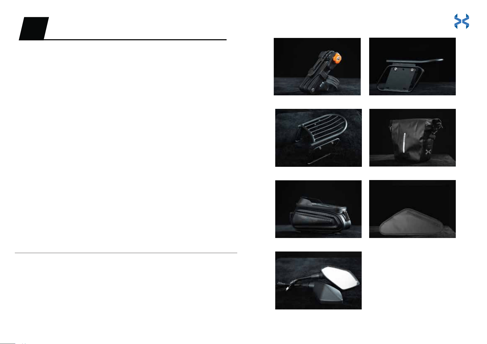
WHAT YOU GET
Folding Lock
Protect your E-Bike with the folding lock! Specifically designed for Altai Pro, this
E-Bike lock will give you peace of mind. Whether you’re running into the store or
heading into work, this lock will keep your E-Bike safe!
Side and Rear Racks
Need that extra bit of storage space for some larger luggage? The Altai Pro side
and rear racks have you covered.
Saddle Bags
These waterproof saddle bags clip onto the side racks of your Altai Pro E-Bike to
keep your belongings safe. Great for your travel gear.
Phone Storage Bag and Triangular Storage Bag
Altai Pro comes with a convenient phone bag, useful for GPS and hands-free calls
while riding. Add some practicality to your Altai Pro with the triangular storage
bags. This bag has a convenient quick-access pocket on the right side, and a
large zippered pocket on the left side.
Dual Mirrors
You’ll always know what’s around you with the Altai Pro dual mirrors. A must-have
for safe riders.
ALTAI PRO ACCESSORIES06
41 42
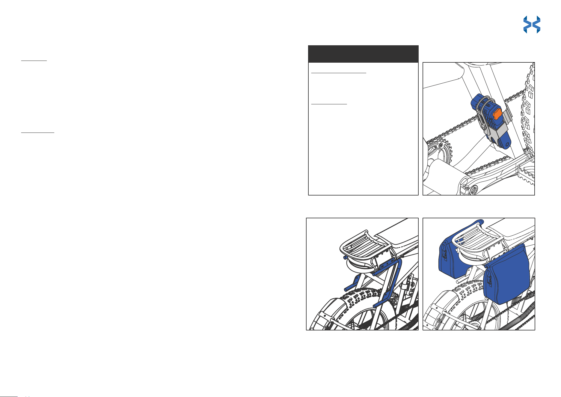
HOW TO INSTALL
Folding Lock
To Install
To Remove
Side Racks and Saddle Bags (racks come pre-installed)
NOTE: If you remove the pre-installed racks and wish to reinstall them, follow the instructions
for the rear rack installation prior to installing the side rack and saddle bags. Do not complete
steps 8 and 9 of the rear rack installation.
.
Add the tube-shaped spacers to the washer screws on the side closest
to the E-Bike. Line them up to the holes at the bottom of the rear rack
plate.
Use the multi-tool to screw the tube-shaped spacers in and tighten
them completely.
Line up the bottom hole of the side rack to the frame of the E-Bike near
the rear tire.
Repeat steps 1-3 for the other side rack.
Tighten all 3 screws with the hex key part of the multi-tool.
Clamp the saddle bags to the side rack frame. Be sure to clip all 3
clamps to the E-Bike frame. The third clamp is located near the bottom of
the saddle bags.
Slide the lock into the lock fastener.
Use the hex wrench piece of the multi-tool to feed both straps through
the fastener barrels until the lock is tight to the E-Bike frame.
Attach the silicone strap to the lock to secure it.
Step 1:
Step 1:
Step 2:
Step 2:
Step 3:
Step 1:
Step 2:
Step 3:
Step 4:
Step 5:
Step 6:
Use the hex wrench to remove the plastic screws and loosen the fastener
straps.
Pull the straps out through both fastener barrels and remove the lock.
Step 1:
To Unlock for the First Time
Step 2:
Turn the combination dials to 0-0-0-0.
Pull the orange plate out.
To Reset the Lock
Step 1:
Step 2:
Step 3:
Step 4:
Step 5:
Step 6:
Turn the dials of the lock to your set
combination.
Pull the orange plate out from the side
of the lock.
Twist the orange plate clockwise one turn.
Press and hold the orange plate into the
lock and turn the dials to the new desired
combination.
Twist the orange plate counterclockwise
one turn and push it back in to set the new
combination.
Scramble the dials to lock.
TO UNLOCK / TO RESET
43 44
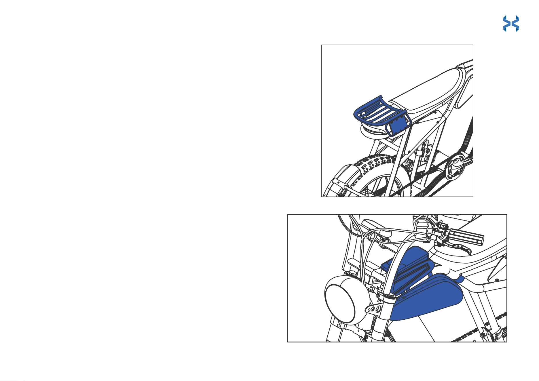
HOW TO INSTALL (continued)
Rear Rack (comes pre-installed. See intstructions if reinstallation is needed)
Phone Storage Bag and Triangular Storage Bag
Fit the washers onto the screws.
Line up the holes on the plates with the holes of the rear rack.
Insert washer screws into the outer two rack holes. Screw the
lug nut onto the washer screw on the opposite side of the plate.
Tighten completely.
Repeat Step 2 for the other side of the rear rack.
Use the hex key to tighten the lug nut completely.
Use the hex key to hold the screw in place and use the
multi-tool to tighten the screws completely.
Use the hex key part of the multi-tool to unscrew both silver
plates at the rear of the E-Bike, one on each side.
Fit the rack onto the rear of the E-Bike. Line up the bottom holes
of the rack plate to the holes on the side of the E-Bike where the
silver plate was removed.
Screw in both washer screws to the bottom of the rack plate to
hold it in place. Tighten completely, but don’t overtighten, as this
could damage the E-Bike.
Repeat for the other side to complete installation.
Step 1:
Step 2:
Step 3:
Step 4:
Step 5:
Step 6:
Step 7:
Step 8:
Step 9:
Step 1:
Step 2:
Step 3:
Step 4:
Place the phone storage bag onto the E-Bike frame with the cell phone
window facing up.
Loosely thread each strap through its respective hook and around the
E-Bike frame. Do not fully tighten the straps yet.
Position the triangular storage bag underneath the phone storage bag.
Make sure the clips are facing up.
Clip the triangular bag onto the E-Bike frame. Pull the adjustable straps to
tighten the loops and secure the bag to the E-Bike frame. Once the
triangular bag is secured, fully tighten the straps of the phone storage bag.
45 46
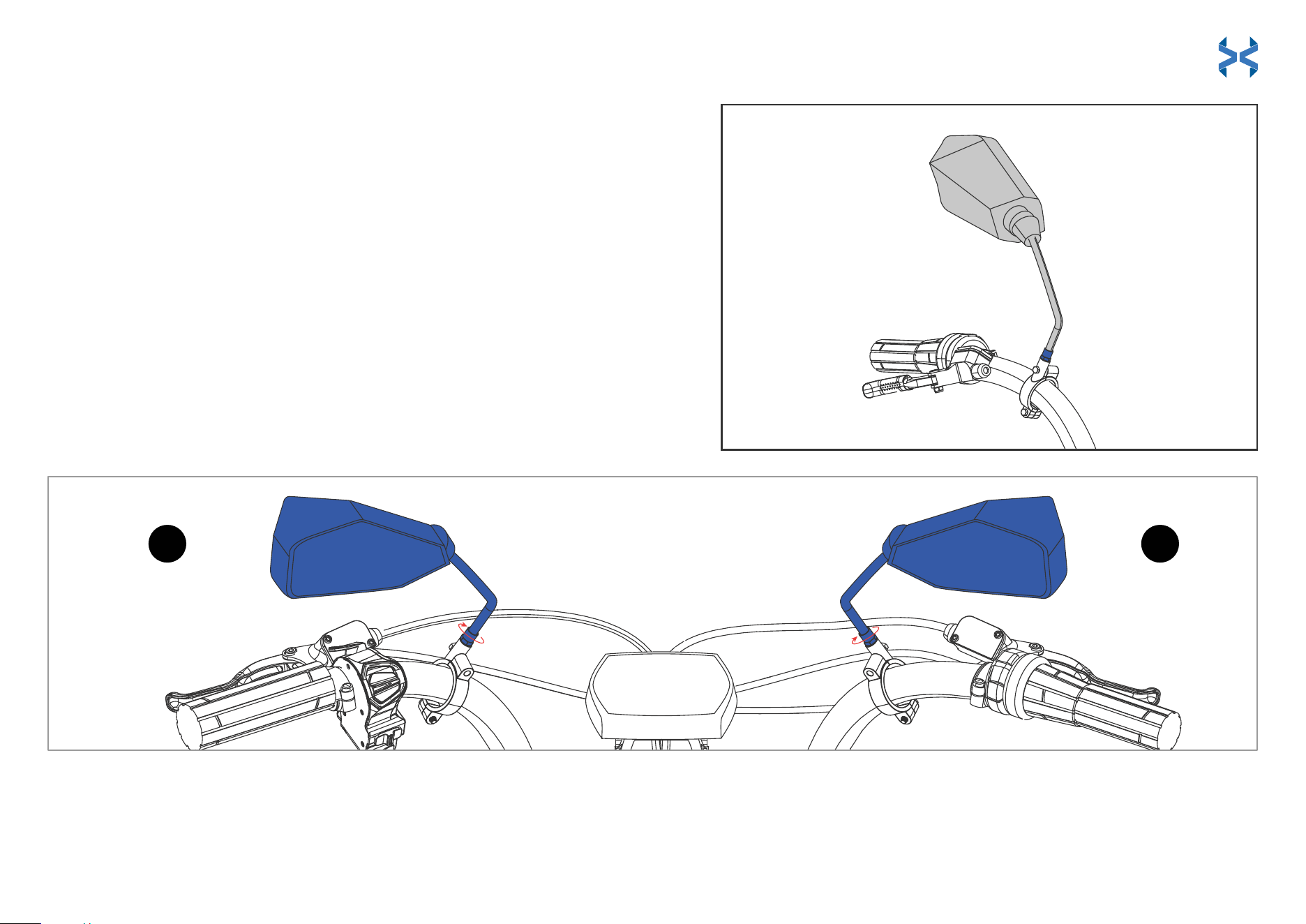
Adjustable Dual Mirrors
RL
HOW TO INSTALL (continued)
Dual Mirrors (mirror brackets come pre-installed for your convenience)
Identify the L (left) and R (right) markings on the mirrors.
Fit mirrors onto the side-appropriate mirror brackets pictured below.
Twist the mirrors halfway into the brackets clockwise.
Twist the nut at the bottom of each mirror shaft clockwise until fully tightened.
Step 1:
Step 2:
Step 3:
Step 4:
Note: If you wish to adjust or remove the mirror brackets, simply unscrew them with
the hex key.
47 48
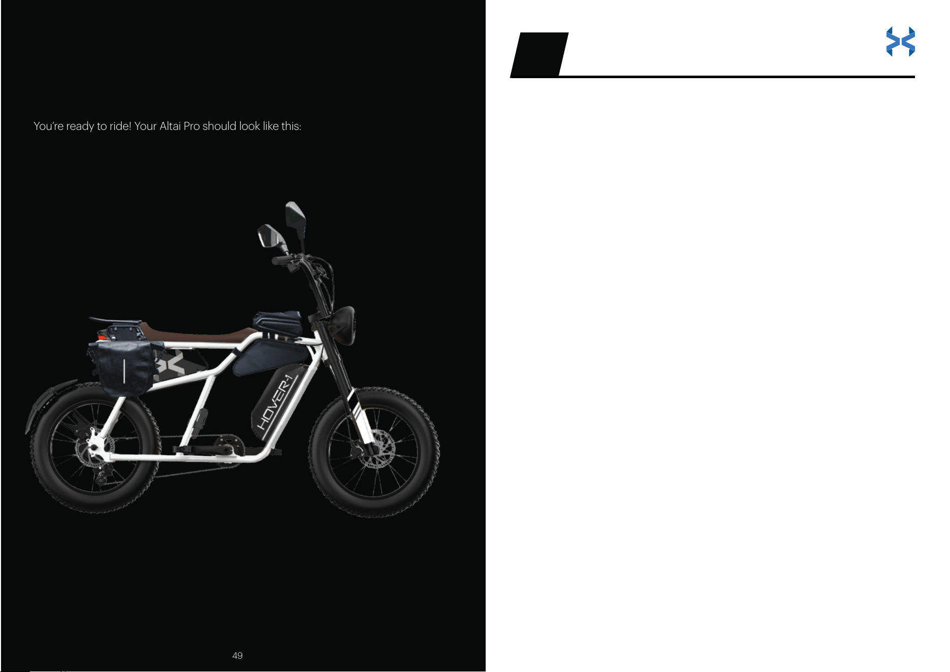
ASSEMBLY IS FINISHED!
You’re ready to ride! Your Altai Pro should look like this:
1. Hover-1 reserves the right to exchange the returned product for a
replacement product of equal or greater value if it is deemed that the
product cannot be repaired within a reasonable time or at a reasonable
cost. The warranty will be fulfilled on a case-by-case basis at Hover-1 Pro
Series’ discretion. Products and/or parts that have been replaced or
exchanged become the property of Hover-1 Pro Series.
2. Warranties that have been activated do not cause the warranty period to
be extended, nor do they trigger a new warranty period. The warranty
period for replacement parts installed ends with the warranty period for
the entire product.
3. The manufacturer’s responsibility shall be limited to the repair or
replacement of the product at its sole discretion.
Warranty in eect
1. Physical abuse, improper installation, modification, or repairs done by an
unauthorized third party.
2. The manufacturer will not take any responsibility if the unit’s failure has
resulted from accidents, abuse, misuse, or unauthorized repair,
modification, or disassembly.
The warranty excludes
This warranty is non-transferable and is limited to the original purchaser only.
It is not transferable to any subsequent purchaser. The manufacturer warranty
only applies to products purchased through an authorized Hover-1 retailer. Any
items purchased from private sellers, online auction sites (including eBay,
liquidators, or items sold “as-is” or “final sale”), or from clearance or going-out-of-
business sales are not covered by the warranty. The warranty period begins
on the date of receipt. Please retain a copy of your receipt as this will be required
to prove the date of purchase should a warranty claim be activated.
WARRANTY07
49 50

51 52
3. Overcharging or damages due to improperly maintaining the lithium-ion
battery installed in the unit.
4. Tires, charge ports, or other parts which are considered consumables
such as glass or plastic or defects based on normal wear and tear.
5. Marginal dierences compared to the target appearance and
workmanship provided, as these have negligible eects on the product’s
fitness for use.
6. Damage to the product caused by chemical or electrochemical eects,
water, moisture, debris, or abnormal conditions.
7. Acts of God.
1. You use any charger other than a genuine Hover-1 Pro Series charger or
the charger designed for your specific model as this could pose a risk of
a serious fire hazard.
2. Repairs or modifications are performed without the written consent of
Hover-1 Pro Series or if a Hover-1 Pro Series product is equipped with
additional parts or accessories not approved for the product by Hover-1
Pro Series.
3. The E-Bike is exposed to water, moisture, mud, dirt, or debris.
4. Units have missing or unreadable serial numbers.
The warranty will be considered void if:
Hover-1 Pro Series is not liable for accidental, indirect, or other
consequential damage of any kind, which leads to usage restrictions, data
loss, and loss of earnings or interruption to business. If you have purchased
an extended warranty, please contact the seller for assistance.
Any further claims are excluded, including those for replacement due to
damage caused to the outside of the product, provided there is no
obligatory legal liability.

Submitting a warranty claim
Hover-1 Pro Series will only accept parcels
that have been assigned an active RMA number.
1. To take advantage of your warranty services, please submit a ticket to
the Hover-1 Pro Series Customer Support by visiting www.hover-1.com
2. Hover-1 Pro Series will attempt to diagnose and resolve your issue.
Hover-1 Pro Series may require photos and/or videos to properly diagnose
the issue and verify warranty eligibility. A copy of your receipt or online
order confirmation with the purchase date, seller, and item name visible is
required. Hover-1 Pro Series reserves the right to verify purchases with the
retailer and/or asset protection databases. Warranty claims will be denied
if the receipt is invalid, cannot be verified, or if the item has been returned
or exchanged. If it is determined that a valid warranty claim exists. Hover-1
Pro Series may send replacement parts or issue an RMA number (Return
Material Authorization) to return the damaged product as Hover-1 deems
appropriate.
3. If an RMA is issued, the package must be shipped within 14 days of the
RMA issuance. If a package is received outside of this time frame, the
package will be refused and returned to the sender.
4. In the event that Hover-1 Pro Series’ technicians find that the product
lacks a manufacturer defect, and the malfunction is due to abuse, water
damage, debris, moisture exposure, or improper maintenance, the
customer will be charged for return shipping and no repairs will be
performed.
YOU EXPRESSLY UNDERSTAND AND AGREE THAT, TO THE MAXIMUM
EXTENT PERMITTED BY APPLICABLE LAW, HOVER-1 PRO SERIES’ TOTAL
LIABILITY IN CONNECTION WITH THE APPLICABLE HOVER-1 PRO SERIES’
PRODUCTS OR THIS WARRANTY POLICY WILL NOT EXCEED THE
AMOUNT ORIGINALLY PAID FOR THE PRODUCT. PARTS AVAILABILITY IS
NOT GUARANTEED.
Submitting a warranty claim Submitting a warranty claim Submitting a warranty claim
This device complies with Part 15 of the FCC Rules. Operation is subject
to the following two conditions: (1) this device may not cause harmful
interference, and (2) this device must accept any interference received,
including interference that may cause undesired operation.
Please note that changes or modifications not expressly approved by the
party responsible for compliance could void the user’s authority to
operate the equipment.
FCC INSTRUCTIONS FOR A CLASS B DIGITAL DEVICE OR PERIPHERAL
Note: This equipment has been tested and found to comply with the
limits for a Class B digital device, pursuant to Part 15 of the FCC Rules.
These limits are designed to provide reasonable protection against
harmful interference in a residential installation. This equipment
generates, uses, and can radiate radio frequency energy and, if not
installed and used in accordance with the instructions, may cause
harmful interference to radio communications. However, there is no
guarantee that interference will not occur in a particular installation. If this
equipment does cause harmful interference to radio or television
reception, which can be determined by turning the equipment off and
on, the user is encouraged to try to correct the interference by one or
more of the following measures:
FCC STATEMENT
AFFIX SERIAL NUMBER LABEL HERE:
REGISTER YOUR HOVER-1 PRO SERIES
AT HOVER-1.COM
53 54
Reorient or relocate the receiving antenna.
Increase the separation between the equipment and receiver.
Connect the equipment into an outlet on a circuit different from
that to which the receiver is connected.
Consult the dealer or an experienced radio/TV technician for help.
•
•
•
•