
ZK-D4330 User Manual
Contents 1
User Manual
Walk Through Metal Detector
ZK-D3180
Date: July 2025
Doc Version: 1.3
English
Thank you for choosing our product. Please read the instructions
carefully before operation. Follow these instructions to ensure that the
product is functioning properly. The images shown in this manual are
for illustrative purposes only.
For further details, please visit our Company’s website
www.zkteco.com
.

ZK-D3180 User Manual
Copyright©2025 ZKTECO CO., LTD. All rights reserved.
Page | 1
Copyright © 2025 ZKTECO CO., LTD. All rights reserved.
Without the prior written consent of ZKTeco, no portion of this manual can be copied or
forwarded in any way or form. All parts of this manual belong to ZKTeco and its subsidiaries
(hereinafter the "Company" or "ZKTeco").
Trademark
is a registered trademark of ZKTeco. Other trademarks involved in this manual
are owned by their respective owners.
Disclaimer
This manual contains information on the operation and maintenance of the ZKTeco
equipment. The copyright in all the documents, drawings, etc. in relation to the ZKTeco
supplied equipment vests in and is the property of ZKTeco. The contents hereof should not be
used or shared by the receiver with any third party without express written permission of
ZKTeco.
The contents of this manual must be read as a whole before starting the operation and
maintenance of the supplied equipment. If any of the content(s) of the manual seems unclear
or incomplete, please contact ZKTeco before starting the operation and maintenance of the
said equipment.
It is an essential pre-requisite for the satisfactory operation and maintenance that the
operating and maintenance personnel are fully familiar with the design and that the said
personnel have received thorough training in operating and maintaining the machine/
unit/equipment. It is further essential for the safe operation of the machine/unit/ equipment
that personnel has read, understood and followed the safety instructions contained in the
manual.
In case of any conflict between terms and conditions of this manual and the contract
specifications, drawings, instruction sheets or any other contract-related documents, the
contract conditions/documents shall prevail. The contract specific conditions/ documents
shall apply in priority.
ZKTeco offers no warranty, guarantee or representation regarding the completeness of any
information contained in this manual or any of the amendments made thereto. ZKTeco does
not extend the warranty of any kind, including, without limitation, any warranty of design,
merchantability or fitness for a particular purpose.
ZKTeco does not assume responsibility for any errors or omissions in the information or
documents which are referenced by or linked to this manual. The entire risk as to the results
and performance obtained from using the information is assumed by the user.

ZK-D3180 User Manual
Copyright©2025 ZKTECO CO., LTD. All rights reserved.
Page | 2
ZKTeco in no event shall be liable to the user or any third party for any incidental,
consequential, indirect, special, or exemplary damages, including, without limitation, loss of
business, loss of profits, business interruption, loss of business information or any pecuniary
loss, arising out of, in connection with, or relating to the use of the information contained in
or referenced by this manual, even if ZKTeco has been advised of the possibility of such
damages.
This manual and the information contained therein may include technical, other inaccuracies
or typographical errors. ZKTeco periodically changes the information herein which will be
incorporated into new additions/amendments to the manual. ZKTeco reserves the right to
add, delete, amend or modify the information contained in the manual from time to time in
the form of circulars, letters, notes, etc. for better operation and safety of the
machine/unit/equipment. The said additions or amendments are meant for improvement
/better operations of the machine/unit/equipment and such amendments shall not give any
right to claim any compensation or damages under any circumstances.
ZKTeco shall in no way be responsible (i) in case the machine/unit/equipment malfunctions
due to any non-compliance of the instructions contained in this manual (ii) in case of
operation of the machine/unit/equipment beyond the rate limits (iii) in case of operation of
the machine and equipment in conditions different from the prescribed conditions of the
manual.
The product will be updated from time to time without prior notice. The latest operation
procedures and relevant documents are available on http://www.zkteco.com
If there is any issue related to the product, please contact us.
ZKTeco Headquarters
Address ZKTeco Industrial Park, No. 32, Industrial Road,
Tangxia Town, Dongguan, China.
Phone +86 769 - 82109991
Fax +86 755 - 89602394
For business-related queries, please write to us at [email protected]
.
To know more about our global branches, visit www.zkteco.com.

ZK-D3180 User Manual
Copyright©2025 ZKTECO CO., LTD. All rights reserved.
Page | 3
About the Company
ZKTeco is one of the world’s largest manufacturer of RFID and Biometric (Fingerprint, Facial,
Finger-vein) readers. Product offerings include Access Control readers and panels, Near &
Far-range Facial Recognition Cameras, Elevator/floor access controllers, Turnstiles, License
Plate Recognition (LPR) gate controllers and Consumer products including battery-operated
fingerprint and face-reader Door Locks. Our security solutions are multi-lingual and localized
in over 18 different languages. At the ZKTeco state-of-the-art 700,000 square foot
ISO9001-certified manufacturing facility, we control manufacturing, product design,
component assembly, and logistics/shipping, all under one roof.
The founders of ZKTeco have been determined for independent research and development of
biometric verification procedures and the productization of biometric verification SDK, which
was initially widely applied in PC security and identity authentication fields. With the
continuous enhancement of the development and plenty of market applications, the team
has gradually constructed an identity authentication ecosystem and smart security ecosystem,
which are based on biometric verification techniques. With years of experience in the
industrialization of biometric verifications, ZKTeco was officially established in 2007 and now
has been one of the globally leading enterprises in the biometric verification industry owning
various patents and being selected as the National High-tech Enterprise for 6 consecutive
years. Its products are protected by intellectual property rights.
About the Manual
This manual introduces the operations of the ZK-D3180 Walk-through Metal Detector.
All figures displayed are for illustration purposes only. Figures in this manual may not be
exactly consistent with the actual products.

ZK-D3180 User Manual
Copyright©2025 ZKTECO CO., LTD. All rights reserved.
Page | 4
Table of Contents
1 OVERVIEW ....................................................................................................... 6
1.1 Introduction ....................................................................................................... 6
1.2 Appearance ........................................................................................................ 6
1.3 Components ....................................................................................................... 7
2 PRODUCT SPECIFICATIONS ............................................................................ 8
2.1 Dimensions ......................................................................................................... 8
2.2 Technical Specifications ................................................................................... 8
3 INSTALLATION SETUP ..................................................................................... 9
3.1 Safety Precautions ............................................................................................ 9
3.2 Instructions to Pedestrians .............................................................................. 9
3.3 Installation Site ................................................................................................10
3.3.1 Stationary Metallic Items ................................................................................................................. 10
3.3.2 Portable Metallic Items ..................................................................................................................... 10
3.3.3 Floor Vibration......................................................................................................................................... 10
3.3.4 Electromagnetic Radiation and Interference .................................................................... 10
3.3.5 Parallel Installation ............................................................................................................................... 10
3.4 Installation Steps .............................................................................................11
4 PERFORMANCE AND TECHNICAL FEATURES ............................................... 17
5 DETECTION ZONES ........................................................................................ 18
5.1 About the Detection Zones ...........................................................................18

ZK-D3180 User Manual
Copyright©2025 ZKTECO CO., LTD. All rights reserved.
Page | 5
5.2 Adjustment of Detection Zone’s Sensitivity ...............................................19
6 CONTROL PANEL DESCRIPTION.................................................................... 20
7 REMOTE CONTROL DESCRIPTION ................................................................ 21
8 OPERATIONAL PROCEDURE.......................................................................... 22
8.1 Standby Interface ............................................................................................22
8.2 Main Menu ........................................................................................................22
8.3 Sensitivity Adjustment ...................................................................................24
8.4 Zone Mode .......................................................................................................26
8.5 Channel Settings .............................................................................................27
8.6 Alarm Settings .................................................................................................28
8.7 Auto Testing .....................................................................................................31
8.8 Security Level ...................................................................................................33
8.9 Scenario ............................................................................................................34
8.10 Log Query .........................................................................................................34
8.11 System Settings ...............................................................................................35
8.12 Web Server .......................................................................................................41
8.13 Default Parameters .........................................................................................43
TROUBLESHOOTING ............................................................................................. 44
PACKING LIST......................................................................................................... 45
WARRANTY CARD .................................................................................................. 46
ZK-D3180 User Manual
Copyright©2025 ZKTECO CO., LTD. All rights reserved.
Page | 6
1 Overview
1.1 Introduction
ZK-D3180 metal-detector is a walk-through metal-detector that is used for security screening
at access points in the prisons, courthouses, and airports. Metal-detectors are highly sensitive
to magnetic metals and have a high detection capability, with less ability to detect
non-magnetic metals. They are used to detect the concealed metal weapons on a person’s
body. It offers high-speed detection capability. It can detect large metal objects like knives
and guns. Its screening capacity is very large when compared to hand-held metal detectors.
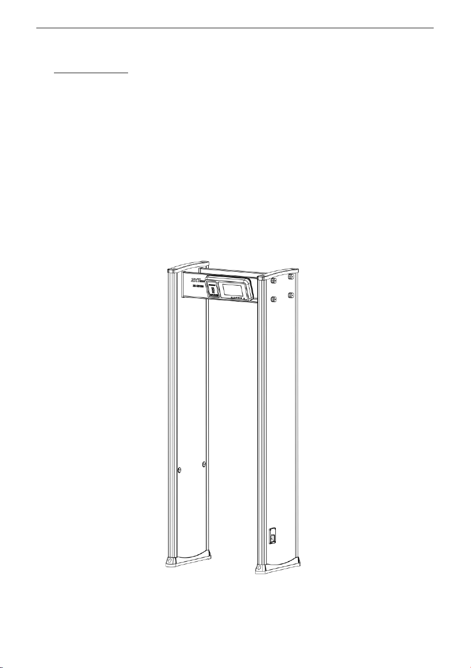
1.2 Appearance
ZK-D3180 User Manual
Copyright©2025 ZKTECO CO., LTD. All rights reserved.
Page | 7
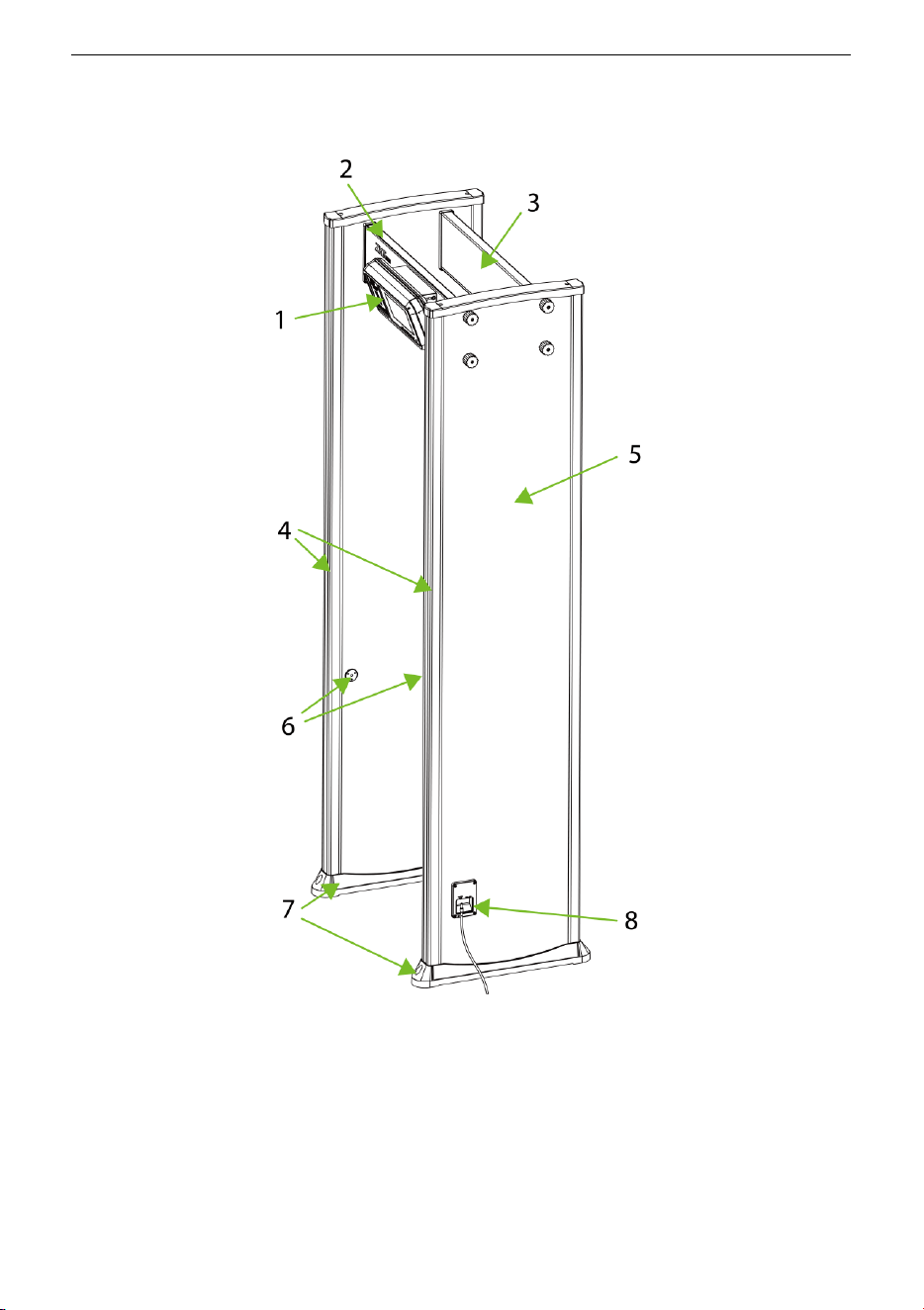
1.3 Components
1. Host 2. Front Beam 3. Rear Beam
4. Alarm Indicator Post 5. Built-in Coil 6. Infrared Sensors
7. Waterproof Foot Cover 8. Power Interface
ZK-D3180 User Manual
Copyright©2025 ZKTECO CO., LTD. All rights reserved.
Page | 8
2 Product Specifications
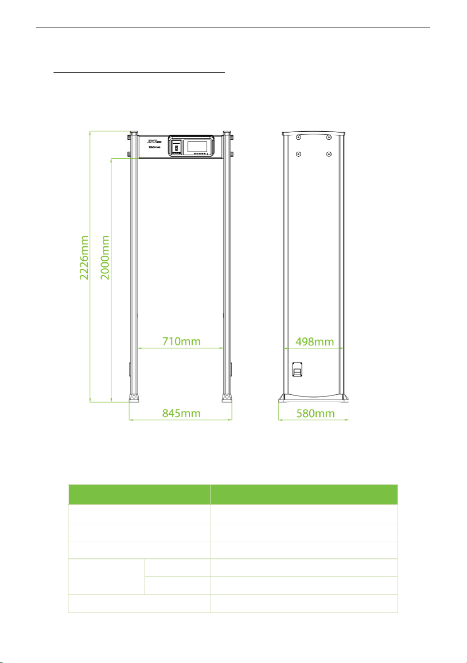
2.1 Dimensions
Front View Side View
2.2 Technical Specifications
Feature Specifications
Power
DC 12V, 3A
Operating Temperature
-20°C to 55°C
Operating Frequency
5.6KHz to 9.6KHz
Dimensions
External
2226(H)x845(W)x580(D)mm
Channel
2000(H)x710(W)x580(D)mm
Weight
55kg

ZK-D3180 User Manual
Copyright©2025 ZKTECO CO., LTD. All rights reserved.
Page | 9
3 Installation Setup
3.1 Safety Precautions
• Install the detector in a stable and smooth area. Make sure that the detector is installed
firmly in the selected area.
• It can be used for both indoor and outdoor purposes. If used outdoor, cover it with a
canopy to protect against rain.
• Before installation, make sure the left and right door panels are placed at the
corresponding location. Avoid high temperatures and wet environments.
• Wait for 1 minute for the self-diagnosis of the detector when it starts. Do not touch the
detector during a security check to avoid false alarm.
• Install the detector away from radio-frequency devices to avoid interference. Make sure
that there is no large metal object or strong magnetic field around the detector for at
least 2 meters.
• Do not hit the detector hardly, as it may cause false alarms.
• Do not disassemble the unit without the guidance of a professional technician.
• Each device has a warranty card, with which users can have their devices maintained or
repaired free of charge within the warranty period.
3.2 Instructions to Pedestrians
• A line must be drawn at 50cm away from the detector. The pedestrians must pass
through the detector one-by-one.
• Pedestrians should line up one-by-one to ensure the smooth operation of the detector.
• Pedestrians should walk at a normal speed. They must not intentionally form a crowd,
rush, walk slowly, or crush the door panel.
• Before passing through the metal detector, the pedestrians must remove all the carried
metal objects (such as keys, mobile phone, watch, coins, etc.), and place it on the
security chute or a table, and pick it up after the security check.
• If the detector alarms when someone passes through, that means there is/are some
metal object(s) hidden in the body. The security guard can use a hand-held metal
detector to accurately detect the hidden position according to the alarm zones.

ZK-D3180 User Manual
Copyright©2025 ZKTECO CO., LTD. All rights reserved.
Page | 10
3.3 Installation Site
The following section describes the requirements of the installation environment.
3.3.1 Stationary Metallic Items
The detector must be installed away at 1m from the stationary metallic items such as
aluminum alloy/stainless-steel windows, doors, etc. to prevent false alarms and affecting the
sensitivity of the detector.
3.3.2 Portable Metallic Items
The portable metallic objects must be kept away at 2 meters from the detector to avoid false
alarms.
3.3.3 Floor Vibration
The installation floor must be flat and fixed to avoid false alarm from the movement of the
people walking through the detector.
3.3.4 Electromagnetic Radiation and Interference
Since the detector uses Bilateral receiver technology, the detector must be installed away at a
distance of at least 1 meter from the sources of electromagnetic radiation or electromagnetic
interference. The parameters that define the distance are determined by the installation
environment and the parameters vary for different installation environments.
The sources of electromagnetic radiation and electromagnetic interference are given below:
• Electrical Control Box, Radiofrequency equipment, Interphone, High Power Motor, Power
Transformer, Ac Power Lines, Thyristor Control Circuit (High Power Switching Power Supply,
Inverter Welder), Engine, Motor, etc.
3.3.5 Parallel Installation
When two detectors are installed parallel to each other, the distance between two detectors
must be greater than 50cm. When three detectors are installed parallel to each other, the
distance between each detector must be greater than 80cm. They must operate at a different
frequency to avoid interference. The distance varies according to the actual working
environment, it is not recommended to mount three detectors in parallel, the frequency can
be adjusted according to the environment.
ZK-D3180 User Manual
Copyright©2025 ZKTECO CO., LTD. All rights reserved.
Page | 11
3.4 Installation Steps
Make sure that the device is installed as per the following installation instructions. If you want
to open the chassis, you should contact the agent for permission. Otherwise, you will bear any
consequence resulting from your actions.
After reading the precautions and checking the packing list, please follow the steps below for
installation.
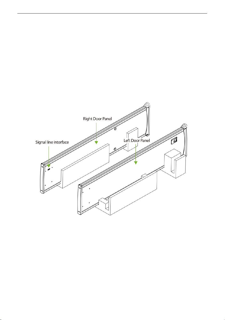
Step 1: Open the package, and then place the left and right door panels on the ground in the
direction shown in the figure 3-1 below. Pay attention to distinguish the left, right and
direction of the door panel (the signal line interface faces upward and inward).
Figure 3-1
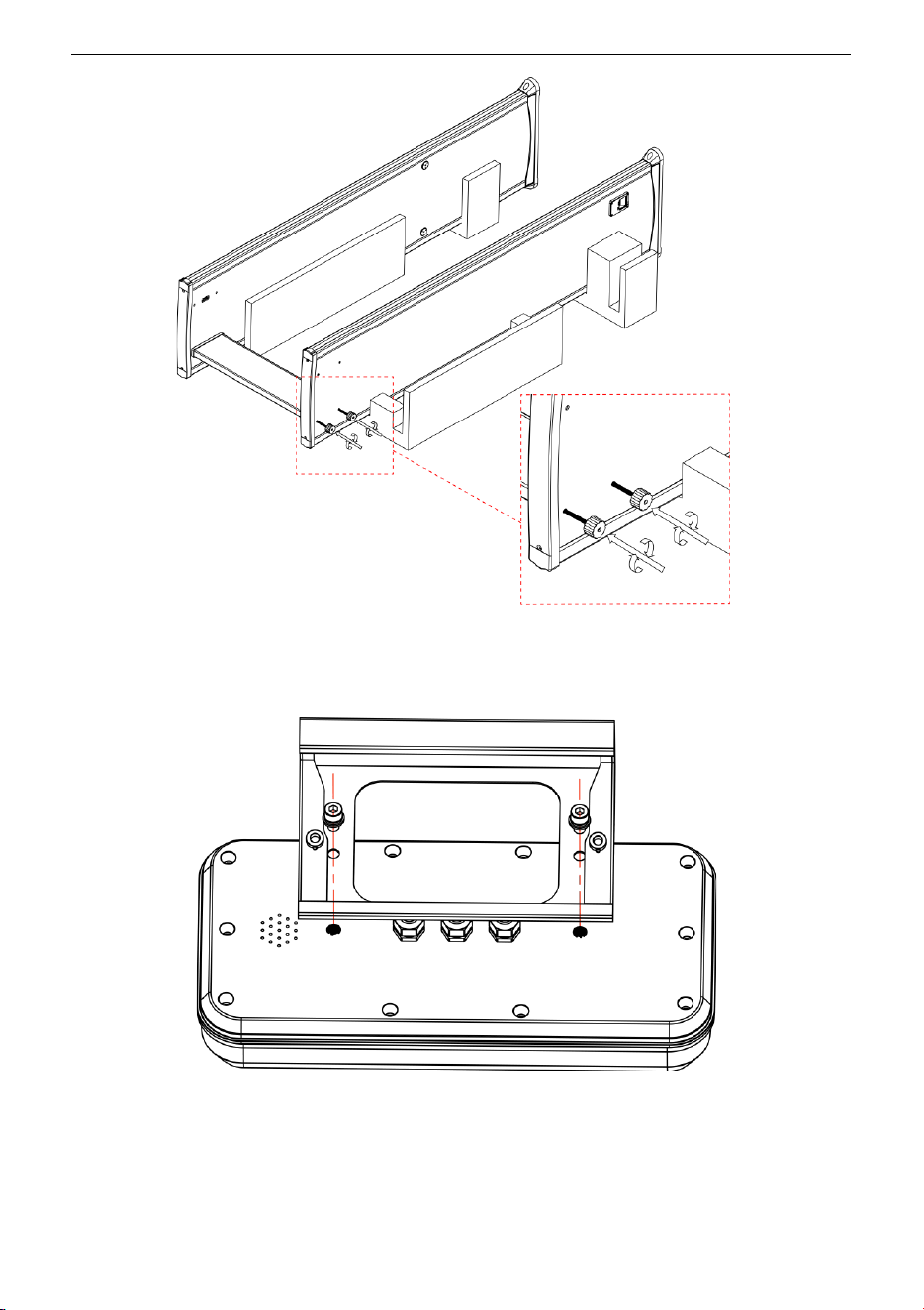
Step 2: Connect the rear beam with the left and right door panels with bolts, as shown in the
figure 3-2 below (note that the bolts are not tightened at this time).
ZK-D3180 User Manual
Copyright©2025 ZKTECO CO., LTD. All rights reserved.
Page | 12
Figure 3-2
Step 3: Install the metal bracket on the host, as shown in the figure 3-3 below.
Figure 3-3
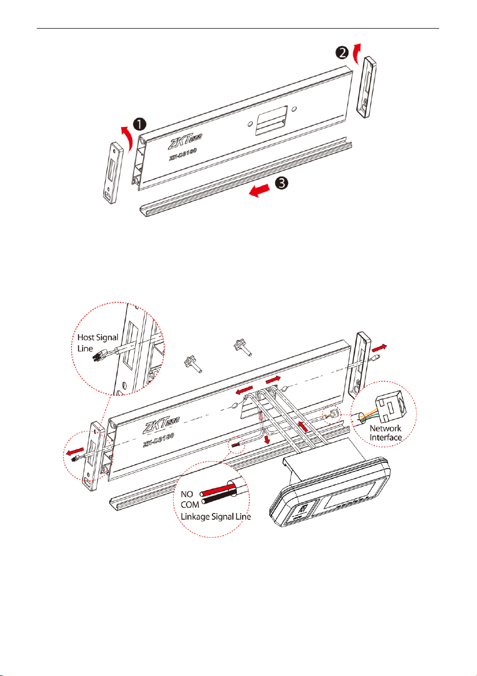
Step 4: Open the left and right cover of the front beam, push out the lower cover, as shown in
the figure 3-4 below.
ZK-D3180 User Manual
Copyright©2025 ZKTECO CO., LTD. All rights reserved.
Page | 13
Figure 3-4
Step 5: Pass the Host Signal Line, the Linkage Signal Line and the Network Interface Line
through the opening of the front beam, as shown in the figure 3-5 below.
Figure 3-5
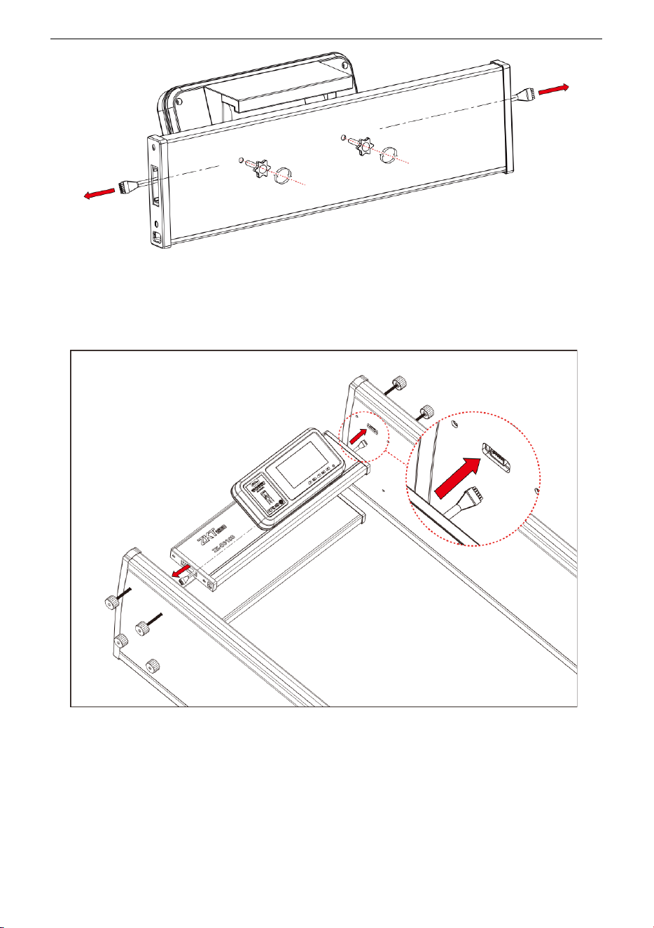
Step 6: After covering the beam cover, connect the host to the front beam with bolts, and
tighten the screws with two Torx Thumb Screws, as shown in the figure 3-6 below.
ZK-D3180 User Manual
Copyright©2025 ZKTECO CO., LTD. All rights reserved.
Page | 14
Figure 3-6
Step 7: Insert the left and right signal wire plugs, as shown in the figure 3-7 below (pay
attention to distinguish the left and right signal wires).
Figure 3-7
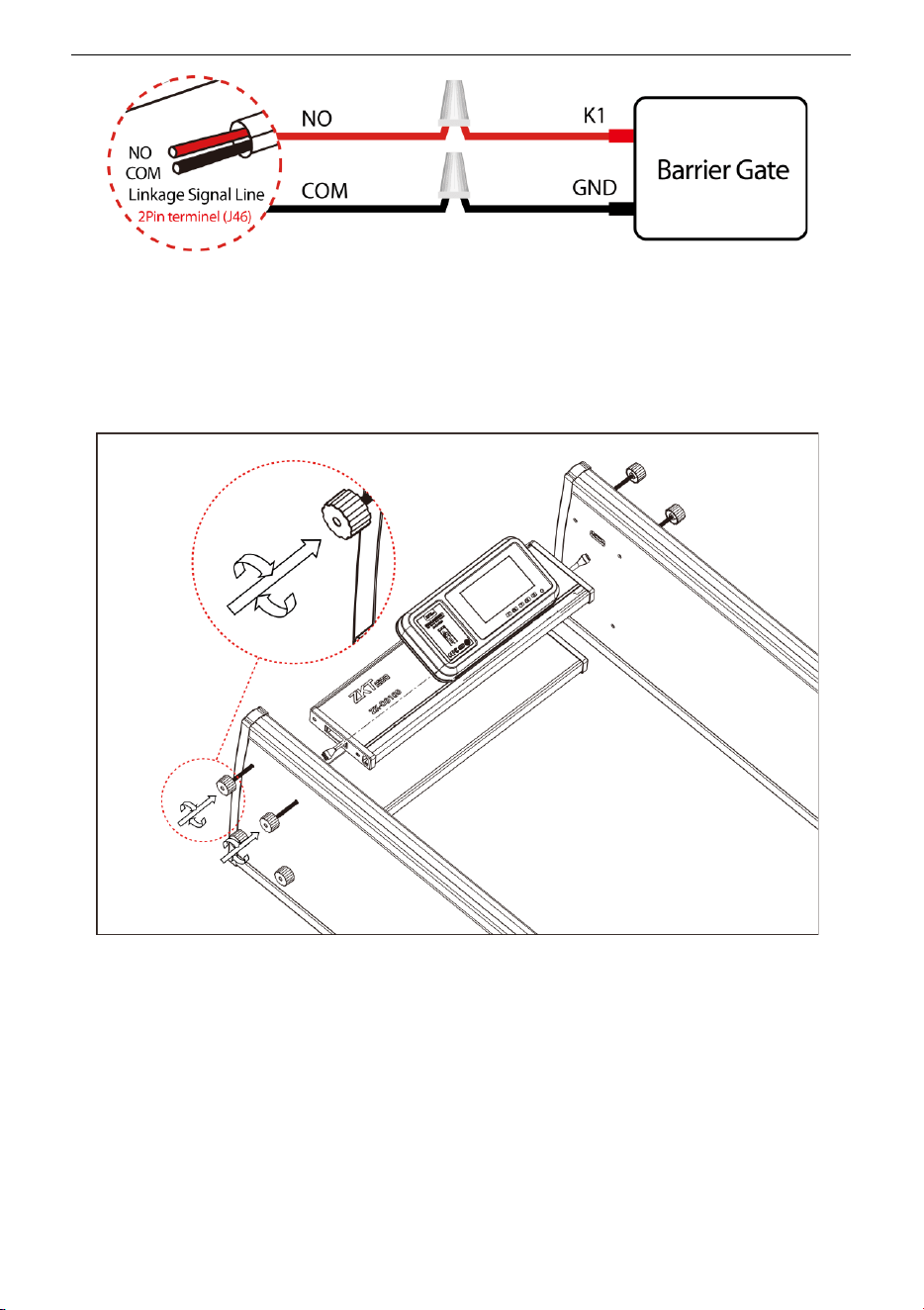
Step 8: The User can connect the linkage signal line with the barrier gate according to the
needs to realize the linkage function of the Walk Through Metal Detector and the barrier gate.
The wiring circuit diagram is shown in the figure 3-8 below.
ZK-D3180 User Manual
Copyright©2025 ZKTECO CO., LTD. All rights reserved.
Page | 15
Figure 3-8
Step 9: Connect the front cross beam with the left and right door panels with bolts and
tighten all the bolts, as shown in the figure 3-9 below.
Figure 3-9
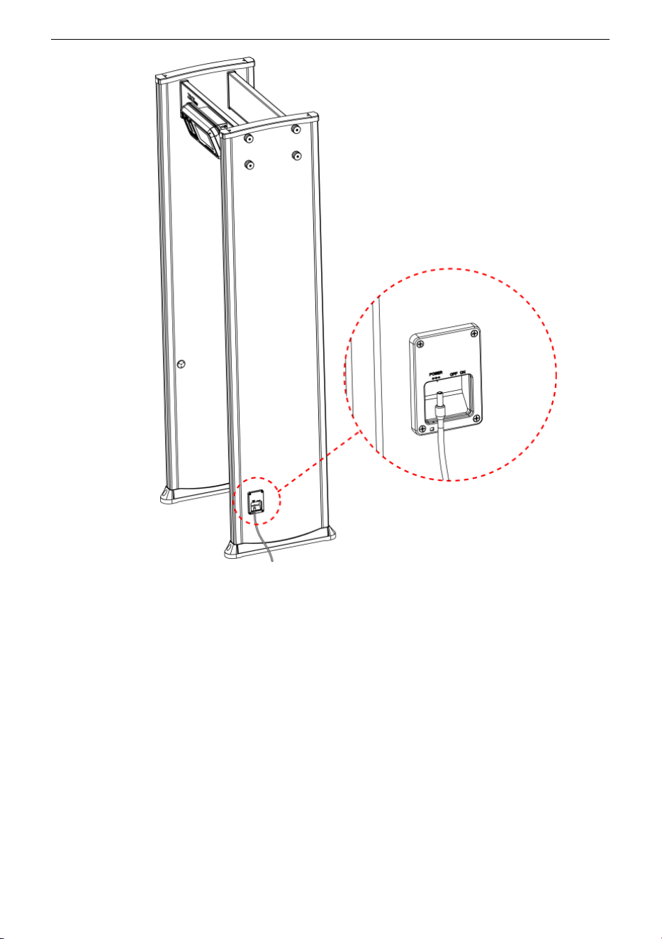
Step 10: Lift and move the security gate to the designated working position, connect the side
power cord, and press the power switch to enter the working state, as shown in the figure
3-10 below.
ZK-D3180 User Manual
Copyright©2025 ZKTECO CO., LTD. All rights reserved.
Page | 16
Figure 3-10

ZK-D3180 User Manual
Copyright©2025 ZKTECO CO., LTD. All rights reserved.
Page | 17
4 Performance and Technical Features
Accurate Positioning: There is an option to select 1, 6, 12, 18, or 33 overlapping
detection zones with bilateral transmit and receive technology. The detection zones
can accurately detect the objects with an intuitive display of the target location.
Micro Processor Technology: The Microprocessor Control Unit generates the
electromagnetic waves for scanning. The scanning rate can be precisely controlled.
Adjustable Sensitivity: ZK-D3180 detection zones have 1 to 500 sensitivity levels.
You can preset the metal size for excluding items like coins, keys, jewelry, buckle, etc.
Visual Sensitivity Adjustment: When you adjust the sensitivity level of a detection
zone, the LED light mapping of the detection zone turns on.
Password Protection: Only the correct password can change the sensitivity and
other parameters. The password contains six digits. The default factory password is
100000.
Digital Pulse Technology: Digital signal processing and filtering system in the
detector has excellent anti-interference ability.
Count Statistics: The detector displays the number of pedestrians passed and Alarm
count accurately.
Harmless: The detector is harmless to heart pacemakers, pregnant women,
magnetic floppy disks, recording tapes, etc.
Waterproof Foot Cover: The waterproof foot cover not only can fix the device firmly
but also protect the device against water.
Safety: The Control Unit case and the panels are waterproof. The cover is made of
PVC synthetic material which makes the detector waterproof, fireproof, and
shockproof.
Easy to install: The detector has an integrated design and it can be effortlessly
installed or disassembled in 15 minutes.
Linkage: Users can connect as needed to realize the linkage function of the metal
detector and the turnstile.
ZK-D3180 User Manual
Copyright©2025 ZKTECO CO., LTD. All rights reserved.
Page | 18
5 Detection Zones
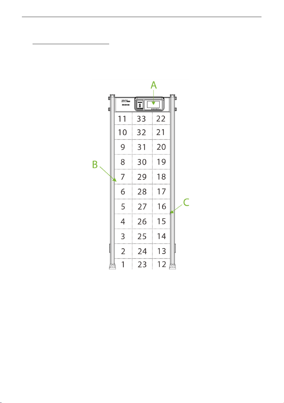
5.1 About the Detection Zones
A. 7'' LCD and control buttons
7" LCD display with control buttons. The standby interface displays the following content:
Device ID Number, Date and Time, Working Channel, Entry Count, Exit Count, Alarm Count,
In-Out Difference, Alarm Rate, Total number of alarms and detection signal strength, etc.
B. Detection zone display
There are two sets of precise positioning LEDs evenly distributed on the left and right door
panels, showing the status of 33 detection zones, as shown in the image above. The zone
indicators can be turned on or off. If the walkthrough metal detector detects metals of the size
that reach or exceed the preset value, the alarm indicator of the detection zone turns on, and
an alarm is generated. (Note: No alarm is generated if the device is in mute state.)

ZK-D3180 User Manual
Copyright©2025 ZKTECO CO., LTD. All rights reserved.
Page | 19
C. Infrared Sensor
After the power is on, the metal detection door starts to work, and when no person or object
passes through the metal detection door, the infrared sensor can effectively stop the alarm,
and it can avoid false alarm. And the number of people passing through is counted accurately.
5.2 Adjustment of Detection Zone’s Sensitivity
1 The device must be in a stable position to achieve the best detection effect (refer 3.3
Installation Site). To check whether the device is in a stable state, perform the following
steps:
a) Power on the detector and check whether it is not shaking after one minute.
b) The device should not alarm when the testing person did not carry any metal
items while walking through the detector.
2 You can exclude the small portable metal objects such as rings, key, belt buckle, shoes,
and so on, by following the steps given below:
a) Choose a small metal as a sample. Increase the sensitivity, so that when the testing
person carries the sample and pass through the detector, and it would alarm.
b) Decrease the sensitivity a little, carry the sample, and pass through the detector
again. If it still alarms, once again reduce the sensitivity, until the device does not
alarm when the sample is passed through.
Note: If you want to decrease the sensitivity in a certain zone, you must only adjust the
sensitivity of the relative zone. After implementing the above adjustments, the metal which
smaller than the sample will not alarm, but the metal objects bigger than the sample can be
detected accurately.
ZK-D3180 User Manual
Copyright©2025 ZKTECO CO., LTD. All rights reserved.
Page | 20
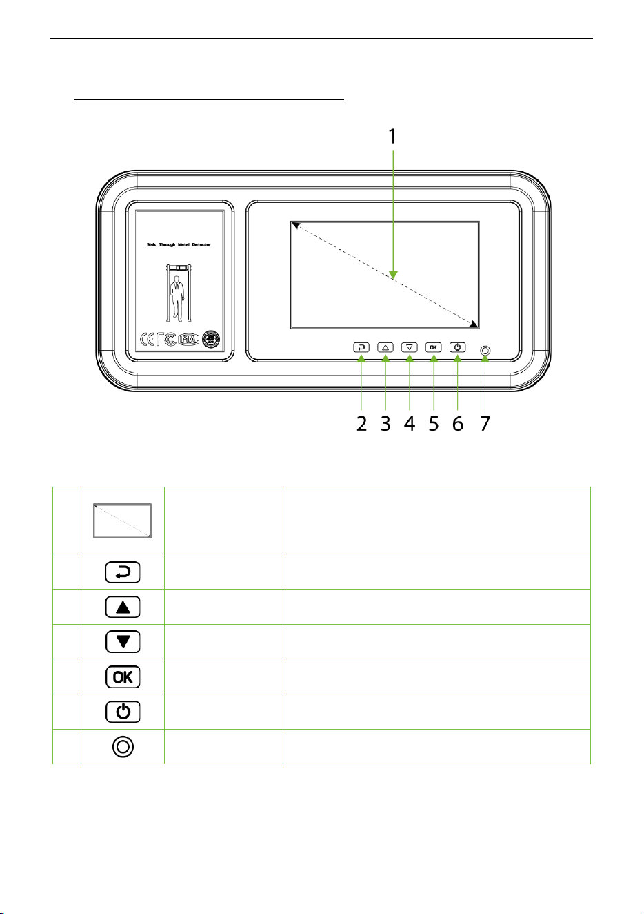
6 Control Panel Description
The components of the Control Panel are given below:
1
7'' LCD
D
isplays information such as the number of
passengers, alarms, detection signal strength,
time, and channel etc.
2
Return Button
Exits the current menu item.
3
Up Button
Selects a menu item or increases a value.
4
Down Button
Selects a menu item or decreases a value.
5
OK Button
Enters a menu item or save settings.
6
Power Button
Power on or off the device.
7
Light
Infrared remote signal receive terminal.
ZK-D3180 User Manual
Copyright©2025 ZKTECO CO., LTD. All rights reserved.
Page | 21
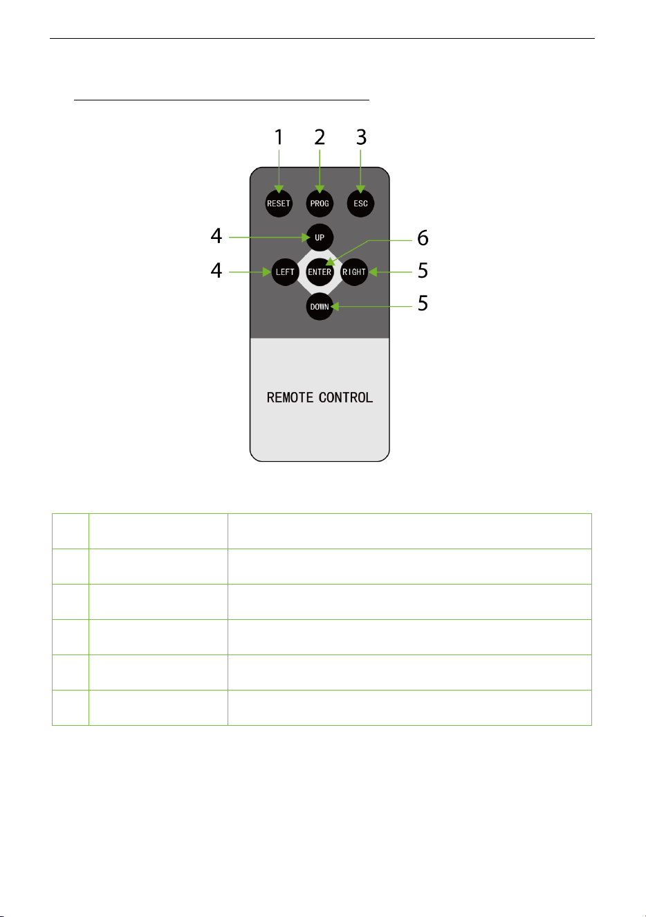
7 Remote Control Description
The buttons of the Remote Control and their description are given below:
1
RESET
Undefined.
2
PROG
Long press 3 seconds to turn off the device.
3
ESC
Exits the current menu item.
4
UP / LEFT
Selects a menu item or increases a value.
5
DOWN / RIGHT
Selects a menu item or decreases a value.
6
ENTER
Menu key, confirmation key and adjustment value.
ZK-D3180 User Manual
Copyright©2025 ZKTECO CO., LTD. All rights reserved.
Page | 22
8 Operational Procedure
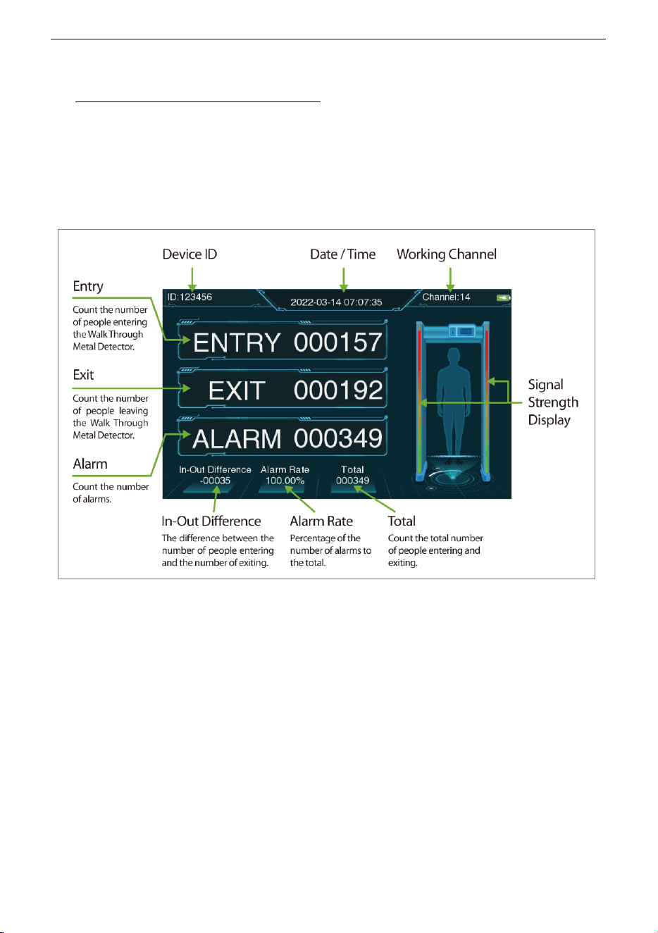
8.1 Standby Interface
Connect the power supply to the detector. After 2 seconds of initialization, the following
standby interface is displayed:
The standby interface displays the following content: Device ID Number, Date and Time,
Working Channel, Entry Count, Exit Count, Alarm Count, In-Out Difference, Alarm Rate, Total
number and detection signal strength, etc.
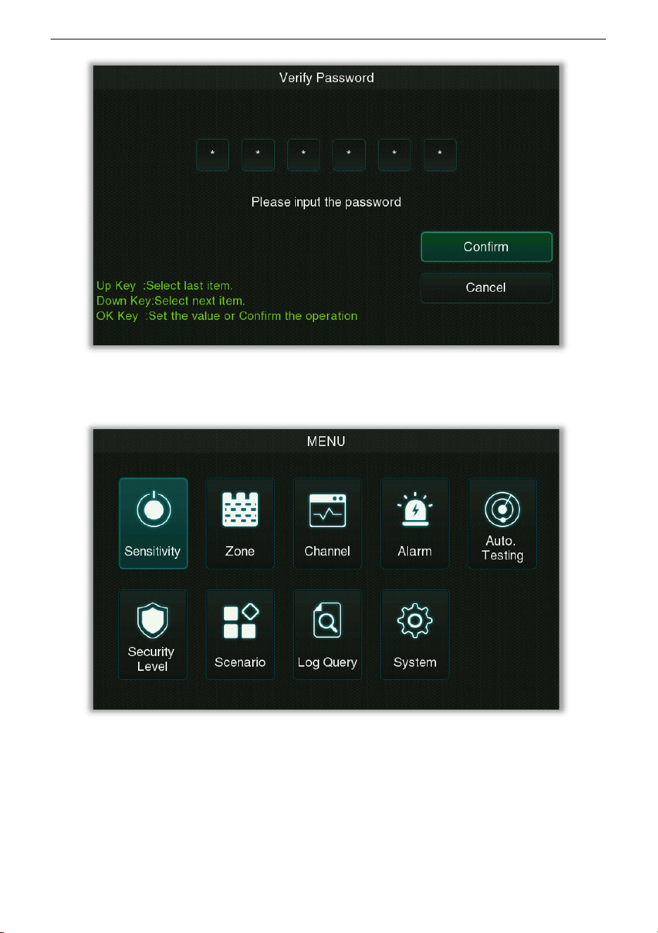
8.2 Main Menu
In the standby mode, press the OK button on the control panel to enter the verification
password input interface. For the first operation of the device, please enter the factory
password of the device: 100000, and select "Confirm" after completion. When the prompt
"Verify Succeed", the verification is completed.
ZK-D3180 User Manual
Copyright©2025 ZKTECO CO., LTD. All rights reserved.
Page | 23
After entering the password successfully, you will enter the main menu interface as shown
below:

ZK-D3180 User Manual
Copyright©2025 ZKTECO CO., LTD. All rights reserved.
Page | 24
Function Description
Menu Descriptions
Sensitivity
Used to set the detection sensitivity threshold of in/out direction,
including Global Sensitivity and Zone Sensitivity.
Zone
Used to set up independent zones to facilitate precise positioning of
detected objects.
Channel
Used to set the frequency band, including Manual Setting and Auto
Setting.
Alarm
Used for alarm settings, including parameters such as Volume, Delay,
Ring Tone, Random Alarm, and Alarm Mode.
Auto. Testing
Automatically detect whether the functions of each modul
e are
available, including Zone, LED and Speaker test.
Security Level
Used to set the security level.
Scenario
It is used to set the application scenarios of the device.
Log Query
Record query function, convenient for users to query the logs saved
in the device.
System
Set the relevant parameters of the system to maximize the function
and display of the device to meet user needs, including Password,
Screen Sleep, Date / Time, Language, Saved Records, Reset, Detect
Mode, Relay Mode, Custom and Direction Setting.
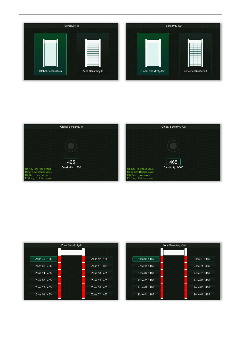
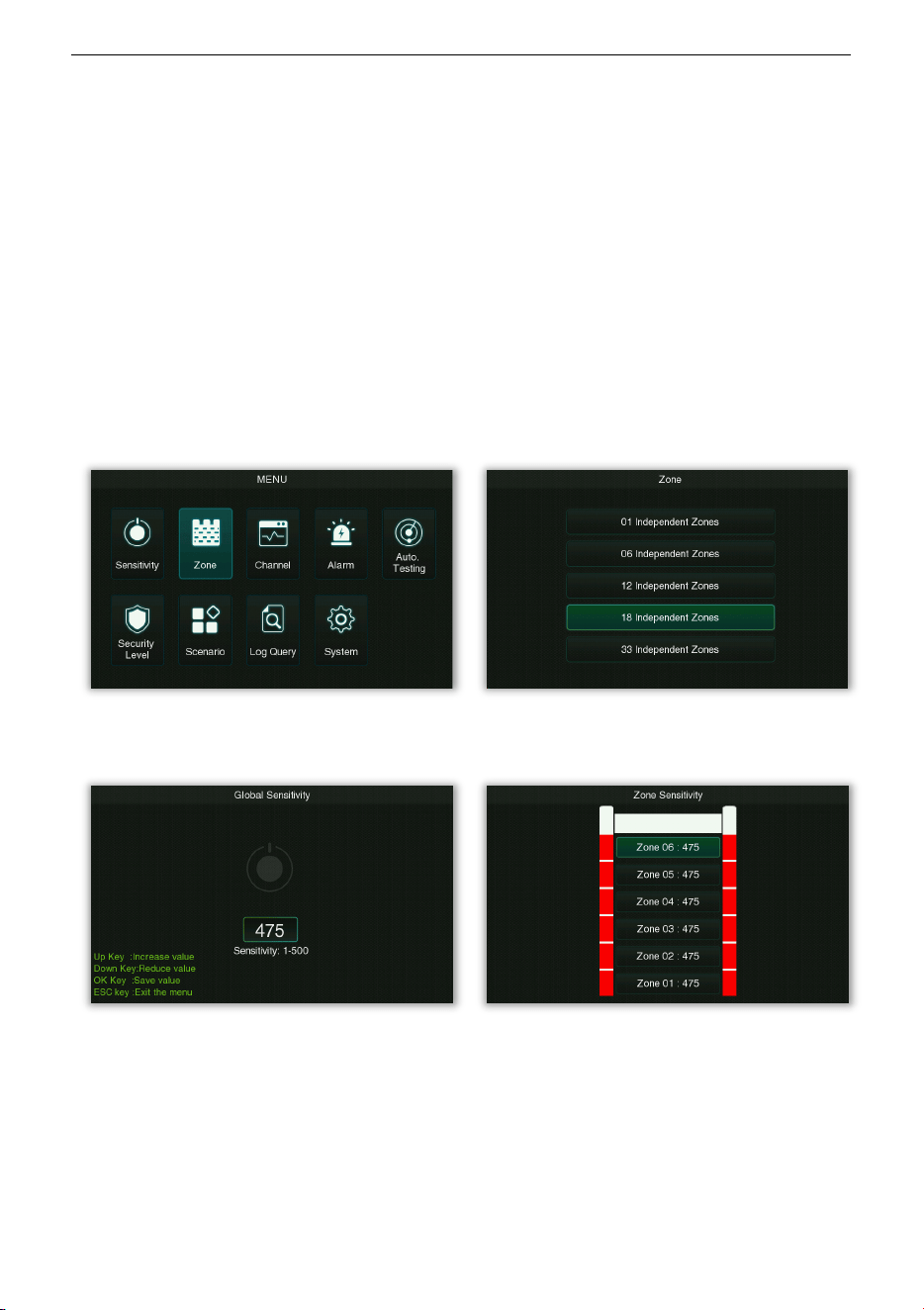
8.3 Sensitivity Adjustment
Select Sensitivity on the Main Menu interface, select Sensitivity-In or Sensitivity-Out and
press OK to set the sensitivity level of in/out direction, as shown in the following:
ZK-D3180 User Manual
Copyright©2025 ZKTECO CO., LTD. All rights reserved.
Page | 25
• Global Sensitivity
Select Global Sensitivity on the Sensitivity-In/Out interface and press OK to get into its
setting interface, as shown in the following:
The larger the global sensitivity threshold the higher the sensitivity, and the effective value is
1 to 500, the default value is 465.
• Zone Sensitivity
Select Zone Sensitivity on the Sensitivity-In/Out interface and press OK to get into its
setting interface, as shown in the following:
ZK-D3180 User Manual
Copyright©2025 ZKTECO CO., LTD. All rights reserved.
Page | 26
When the partition is selected for setting, the indicator light of the corresponding partition on
the walk through metal detector will light up. The greater the regional sensitivity threshold,
the higher the sensitivity, the effective value is 1-500, and the default value is 465.
Note: You need to set up independent defense zones in the Defense Zone Settings interface
first.
8.4 Zone Mode
In the zone mode, you can select the number of independent zone according to the
operational needs of the device.
Select Zone on the Main Menu interface, and press OK to select the particular zone settings,
as shown in the following:
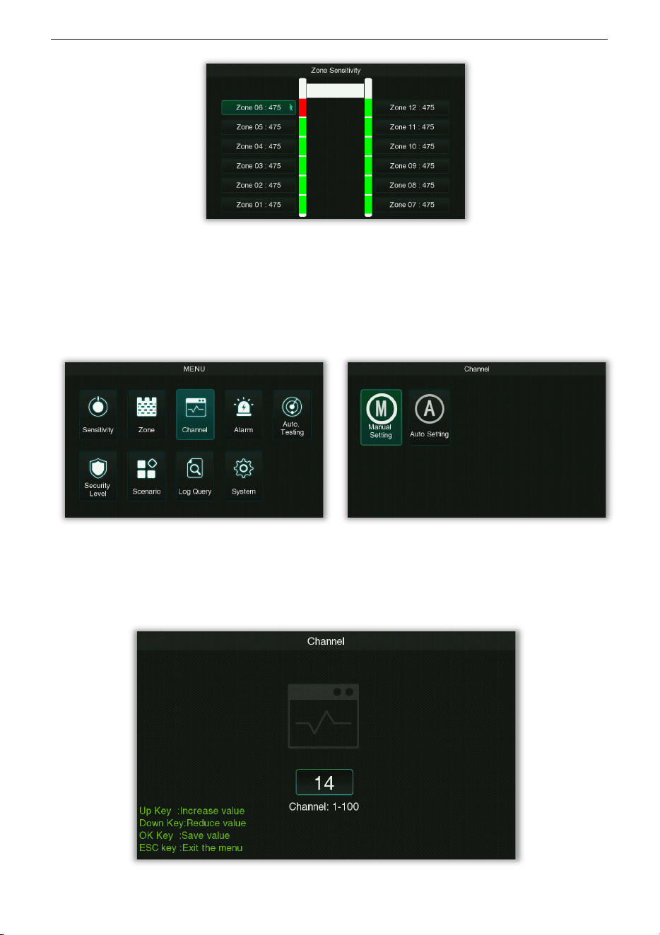
Remark: Different independent zones, the Zone Sensitivity setting interface is as follows:
1-zone 6-zone
ZK-D3180 User Manual
Copyright©2025 ZKTECO CO., LTD. All rights reserved.
Page | 27
12/18/33-zone
8.5 Channel Settings
Select Channel on the Main Menu interface, and press OK to enter the band setting interface,
as shown in the following:
• Manual Setting
Select Manual Setting on the Channel interface and press OK to get into its setting interface.
The channel range is from 1 to 100, the default value is 14.
ZK-D3180 User Manual
Copyright©2025 ZKTECO CO., LTD. All rights reserved.
Page | 28
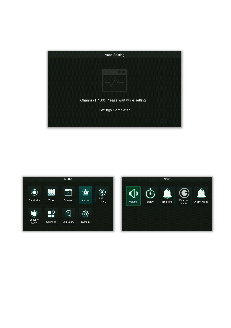
• Auto Setting
Select Auto Setting on the Channel interface and press OK to get into its setting interface, as
shown in the following:
8.6 Alarm Settings
Select Alarm on the Main Menu interface, and press OK to enter the alarm settings interface,
as shown in the following:
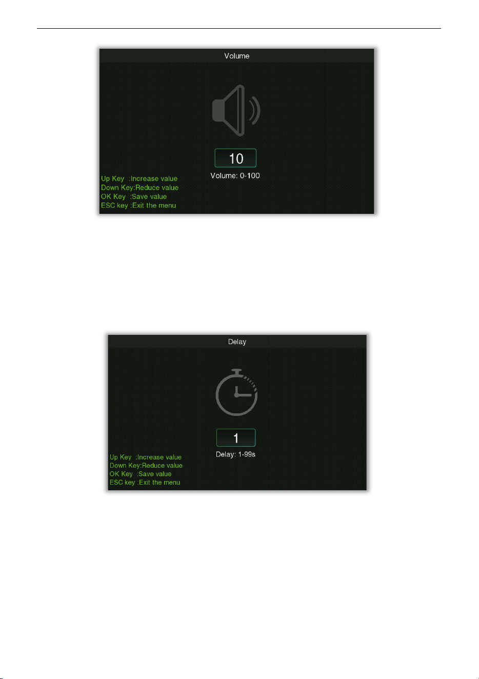
• Volume
Select Volume on the Alarm setting interface, and press OK to enter the alarm volume
settings interface, as shown in the following:
ZK-D3180 User Manual
Copyright©2025 ZKTECO CO., LTD. All rights reserved.
Page | 29
Used to set the alarm volume, the larger the value the higher the volume, valid values are 0 to
100, the default value is 80.
• Delay
Select Delay on the Alarm setting interface, and press OK to enter the alarm delay duration
setting, as shown in the following:
Used to set the length of time for the alarm to ring, the effective value is 1 to 99 seconds, the
default value is 1 second.
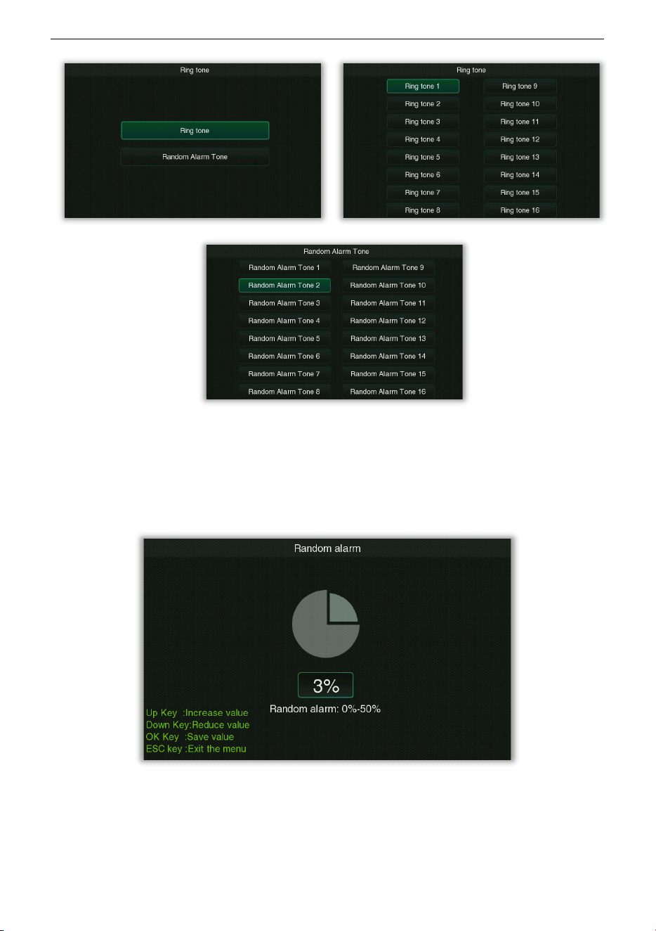
• Ring Tone
Select Ring Tone on the Alarm setting interface, select Ring tone or Random Alarm Tone
and press OK to enter the alarm ring setting interface, as shown in the following:
ZK-D3180 User Manual
Copyright©2025 ZKTECO CO., LTD. All rights reserved.
Page | 30
It is used to set the ringtone when the alarm rings, a total of 16 ringtones can be selected.
• Random alarm
Select Random alarm on the Alarm setting interface, and press OK to enter the random alarm
setting interface, as shown in the following:
Under normal circumstances, the alarm is generated when the amount of metal signal
reaches the set sensitivity threshold, while it can pass normally when it is less than the
threshold. When a random alarm value is set, there will be a n% probability that a normal pass
without alarm will be turned into an alarm, so that it can be checked and confirmed again
manually.
ZK-D3180 User Manual
Copyright©2025 ZKTECO CO., LTD. All rights reserved.
Page | 31
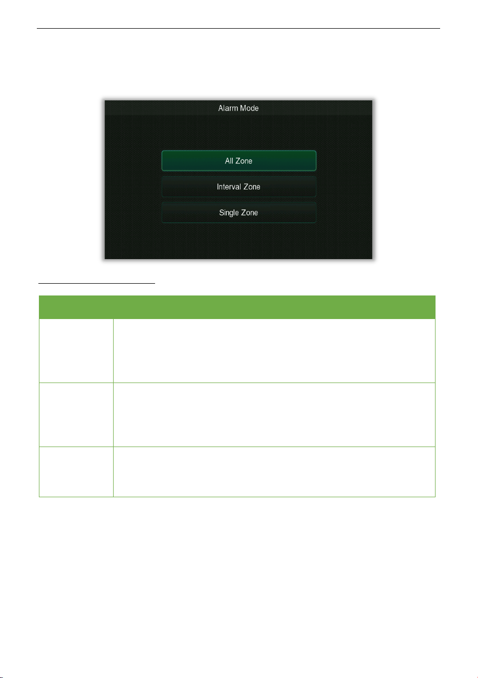
• Alarm Mode
Select Alarm Mode on the Alarm setting interface, and press OK to enter the alarm mode
setting interface, as shown in the following:
Function Description
Menu Descriptions
All Zone
In the All Zone alarm mode, when the detected metal content reaches or
exceeds the set metal content, the area alarm light of the detected metal
will be serial lit, and an alarm will sound at the same time. Suitable for
normal mode.
Interval Zone
In the Interval Zone alarm mode, the zone warning lights that detect
strong metal content will light up at intervals, that is, two consecutive
zones will not light up at the same time. Facilitates identification and
focused detection of stronger zones by security personnel.
Single Zone
In the Single Zone alarm mode, only the zone with the strongest metal
content is detected and the alarm lamp lights up. Facilitate the security
personnel to precisely focus on the area for detection.
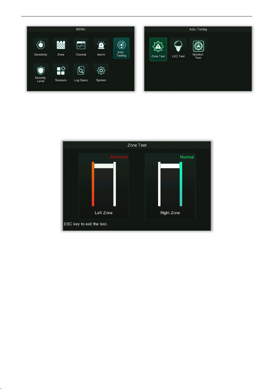
8.7 Auto Testing
Select Auto Testing on the Main Menu interface, and press OK to enter this option where the
system self-checks its functions. As shown in the following:
ZK-D3180 User Manual
Copyright©2025 ZKTECO CO., LTD. All rights reserved.
Page | 32
• Zone Test
Select Zone Test on the Alarm setting interface, and press OK to enter the partition test. The
test example is shown below.
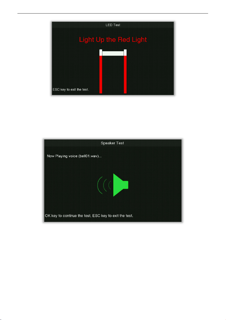
• LED Test
Select LED Test on the Alarm setting interface, and press OK to enter the lighting test. The test
example is shown below.
ZK-D3180 User Manual
Copyright©2025 ZKTECO CO., LTD. All rights reserved.
Page | 33
• Speaker Test
Select Speaker Test on the Alarm setting interface, and press OK to enter the voice test. The
test example is shown below.
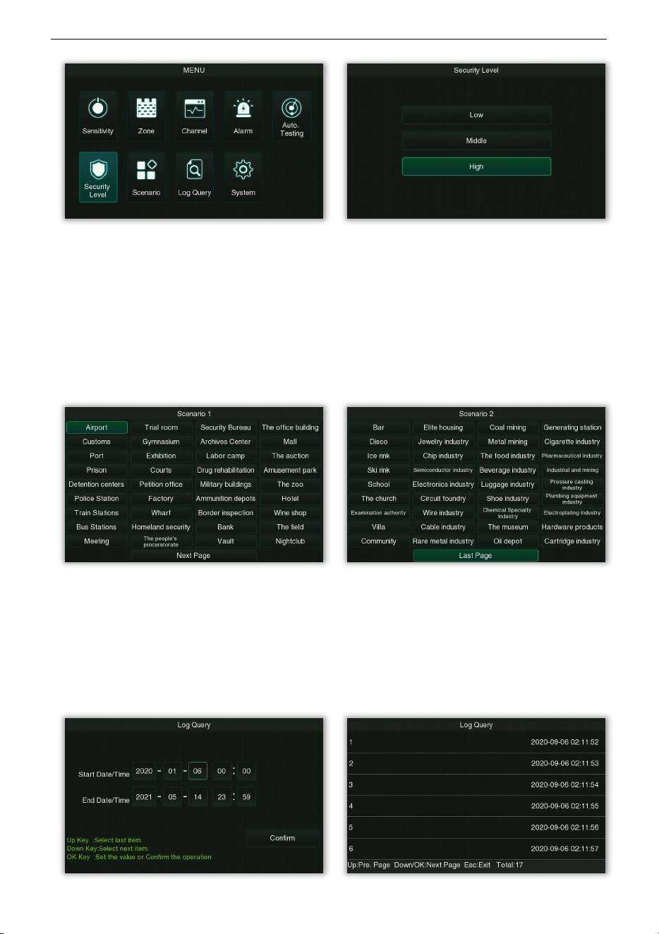
8.8 Security Level
Select Security Level on the Main Menu interface, and press OK to enter the security level
setting interface, as shown in the following:
ZK-D3180 User Manual
Copyright©2025 ZKTECO CO., LTD. All rights reserved.
Page | 34
Three security levels can be set as Low, Middle and High. The higher the security level, the
higher the corresponding sensitivity.
8.9 Scenario
Select Scenario on the Main Menu interface, and press OK to enter the application scenario
setting interface, as shown in the following:
You can choose different scenarios in Scenario 1 and Scenario 2 for setting.
8.10 Log Query
Select Log Query on the Main Menu interface, and press OK to enter the log query interface,
as shown in the following:
ZK-D3180 User Manual
Copyright©2025 ZKTECO CO., LTD. All rights reserved.
Page | 35
Each page of the query result displays 6 historical alarm records, and the total number of
alarm records can be viewed at the lower right corner of the page.
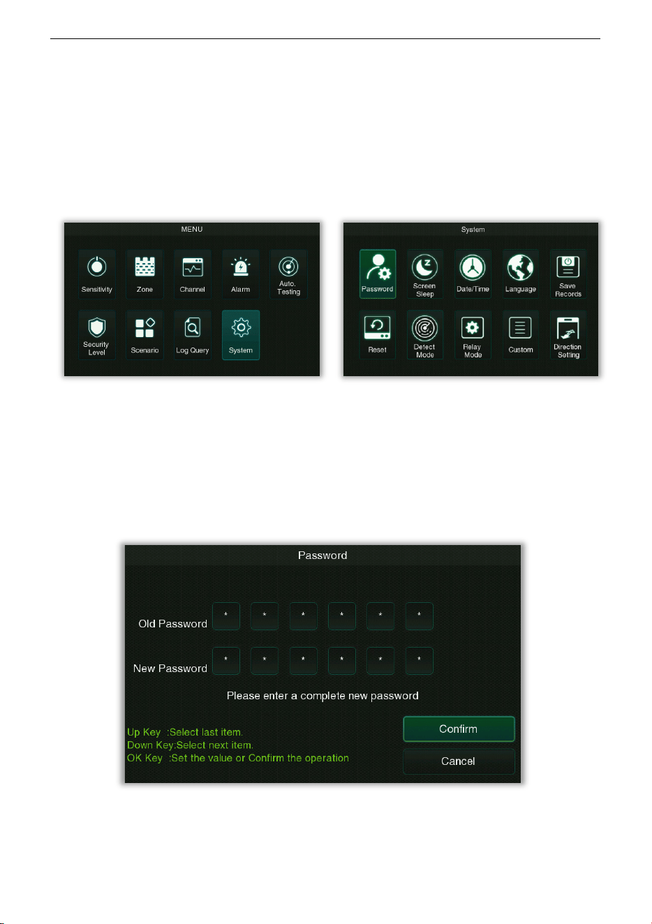
8.11 System Settings
Select System on the Main Menu interface, and press OK to enter the system settings
interface, as shown in the following:
It is used to set the relevant parameters of the system so that the device can maximize the
user requirements in terms of function, display, etc.
• Password
Select Password on the System setting interface, and press OK to enter the password setting
interface, as shown in the following:
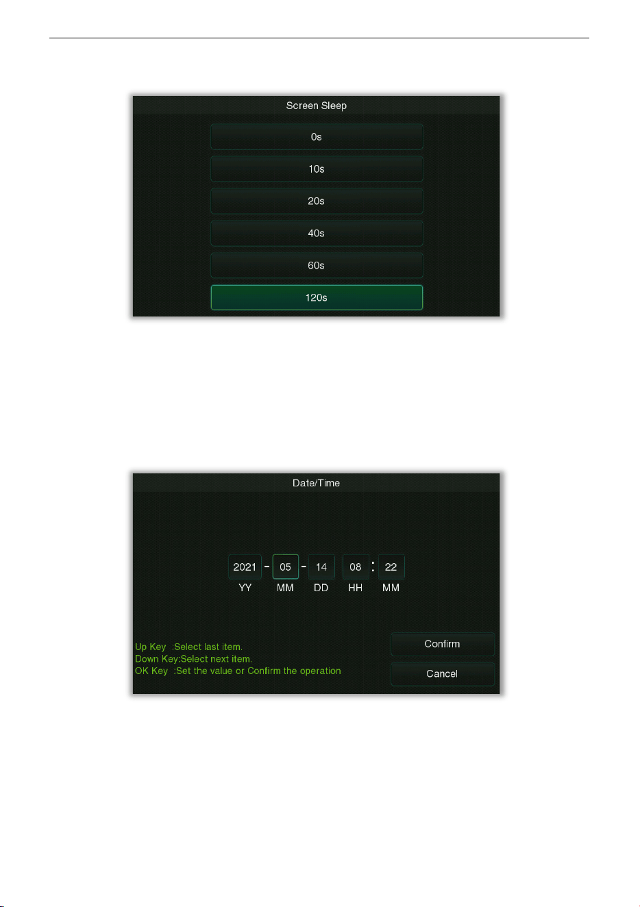
• Screen Sleep
Select Screen Sleep on the System setting interface, and press OK to enter the screen
ZK-D3180 User Manual
Copyright©2025 ZKTECO CO., LTD. All rights reserved.
Page | 36
hibernation setting interface, as shown in the following:
You can set the screen hibernation duration here, there are 0s, 10s, 20s, 40s, 60s and 120s
optional. Note: The 0s means the screen will not hibernation.
• Date/Time
Select Date/Time on the System setting interface, and press OK to enter the system Date &
Time setting interface, as shown in the following:
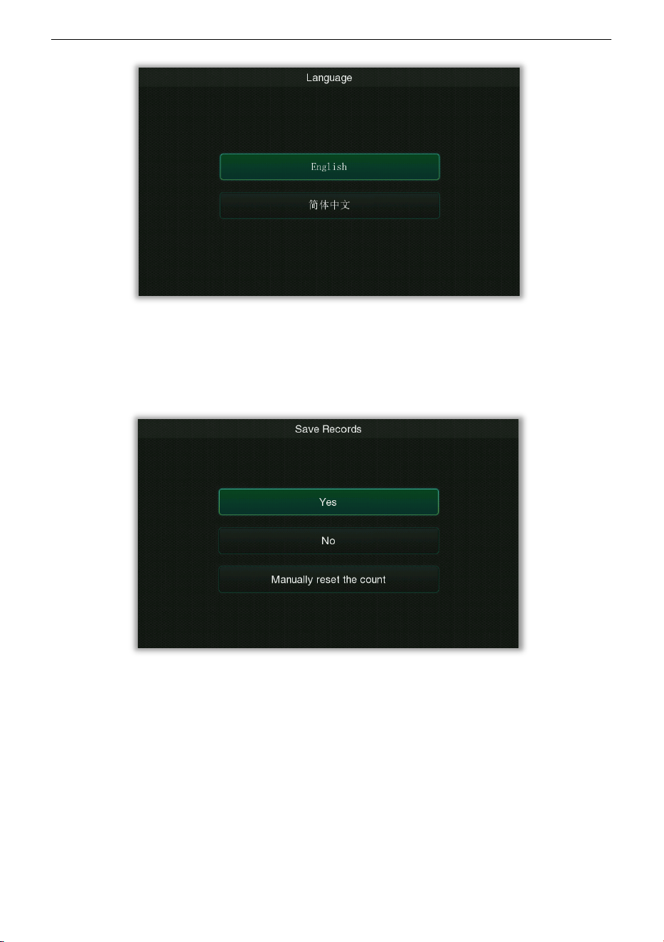
• Language
Select Language on the System setting interface, and press OK to enter the language setting
interface, as shown in the following:
ZK-D3180 User Manual
Copyright©2025 ZKTECO CO., LTD. All rights reserved.
Page | 37
• Save Records
Select Save Records on the System setting interface, and press OK to enter the setting
interface, as shown in the following:
It is used to set whether to save the number of alarm records after the device is turned off,
select "Yes" to save, select "No" to clear, and select "Manually reset the count" to clear count
manually.
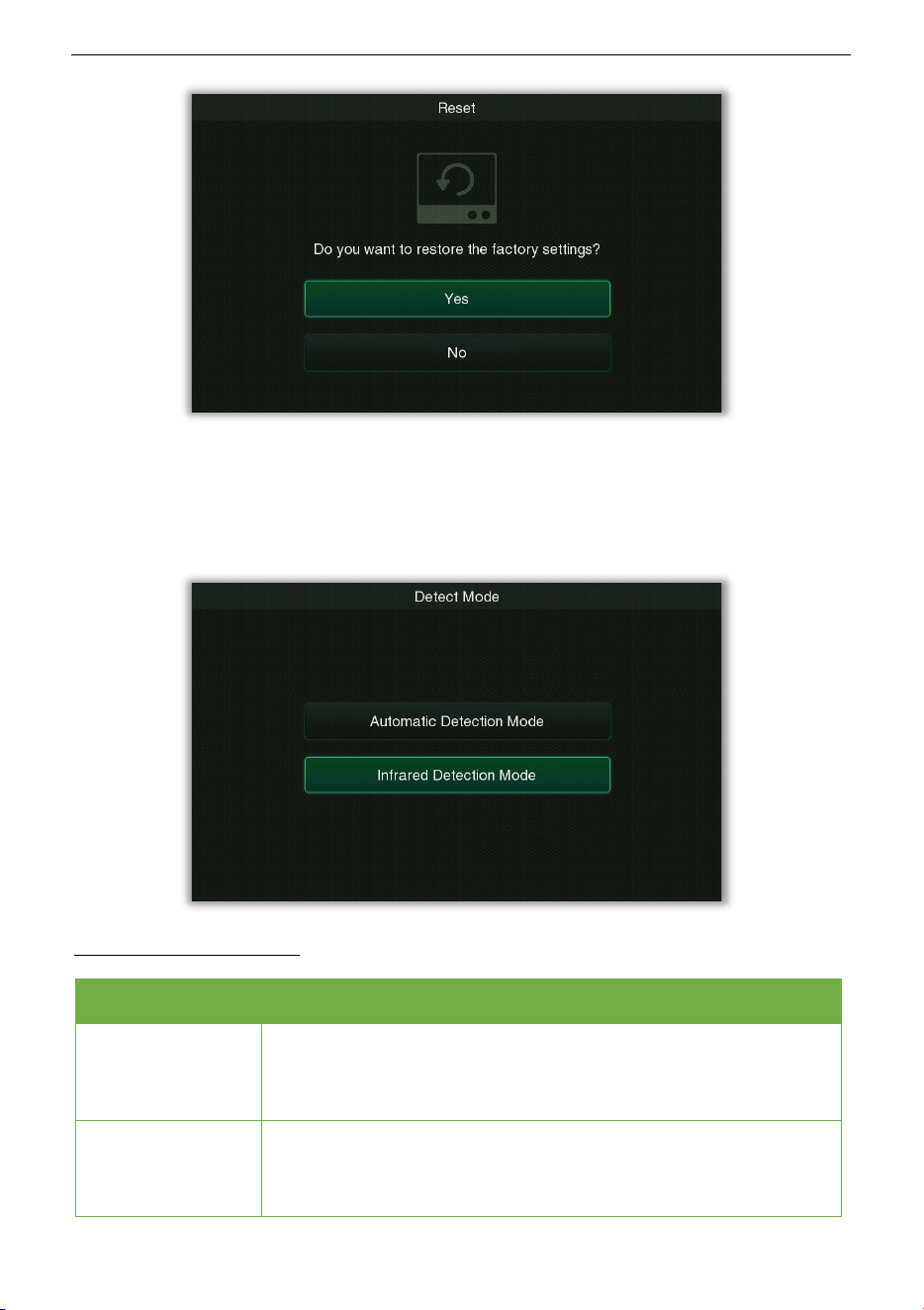
• Reset
Select Reset on the System setting interface, and press OK to enter the restore factory
settings interface, as shown in the following:
ZK-D3180 User Manual
Copyright©2025 ZKTECO CO., LTD. All rights reserved.
Page | 38
• Detect Mode
Select Detect Mode on the System setting interface, and press OK to enter the detect mode
setting interface, as shown in the following:
Function Description
Menu Descriptions
Automatic
Detection Mode
In this mode, an alarm is generated when the amount of metal
signal reaches the set sensitivity
threshold, and no counting
statistics are performed.
Infrared Detection
Mode
In this mode, when the infrared detector is triggered and the
amount of metal signal reaches the set sensitivity threshold, an
alarm will be generated, and counting statistics will be performed.
ZK-D3180 User Manual
Copyright©2025 ZKTECO CO., LTD. All rights reserved.
Page | 39
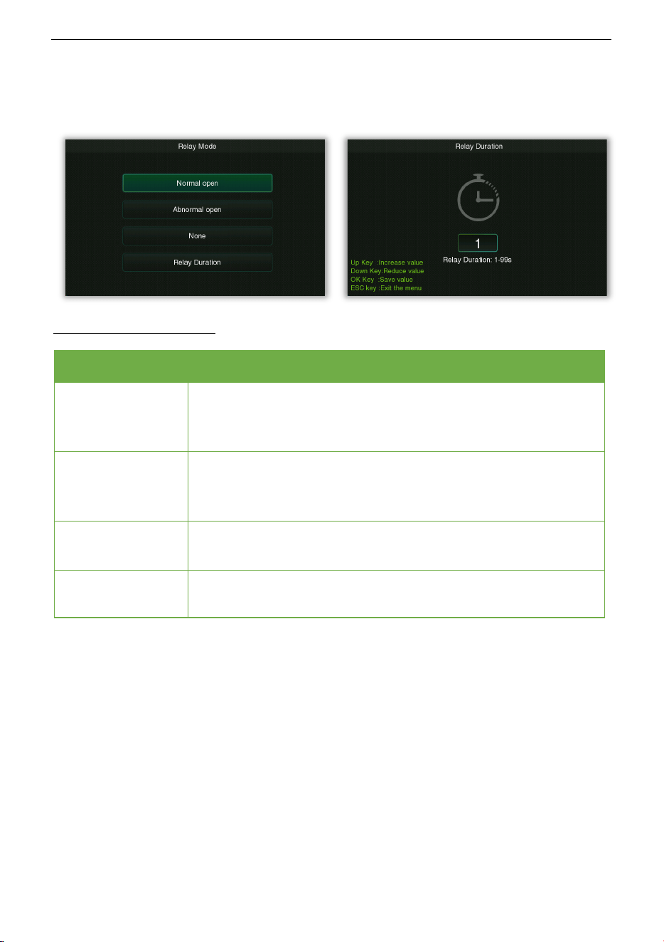
• Relay Mode
Select Relay Mode on the System setting interface, and press OK to enter the relay control
setting interface, as shown in the following:
Function Description
Menu Descriptions
Normal open
In this mode, when the metal content carried is less than the alarm
threshold, the relay will be triggered to output a switch signal when
the machine does not alarm;
Abnormal open
In this mode, when the metal content exceeds the alarm threshold,
the machine will trigger the relay to output a switch signal when
the machine alarms;
None
Means that the relay is always in the off state and does not output a
switch signal.
Relay Duration
Set the duration of the relay.
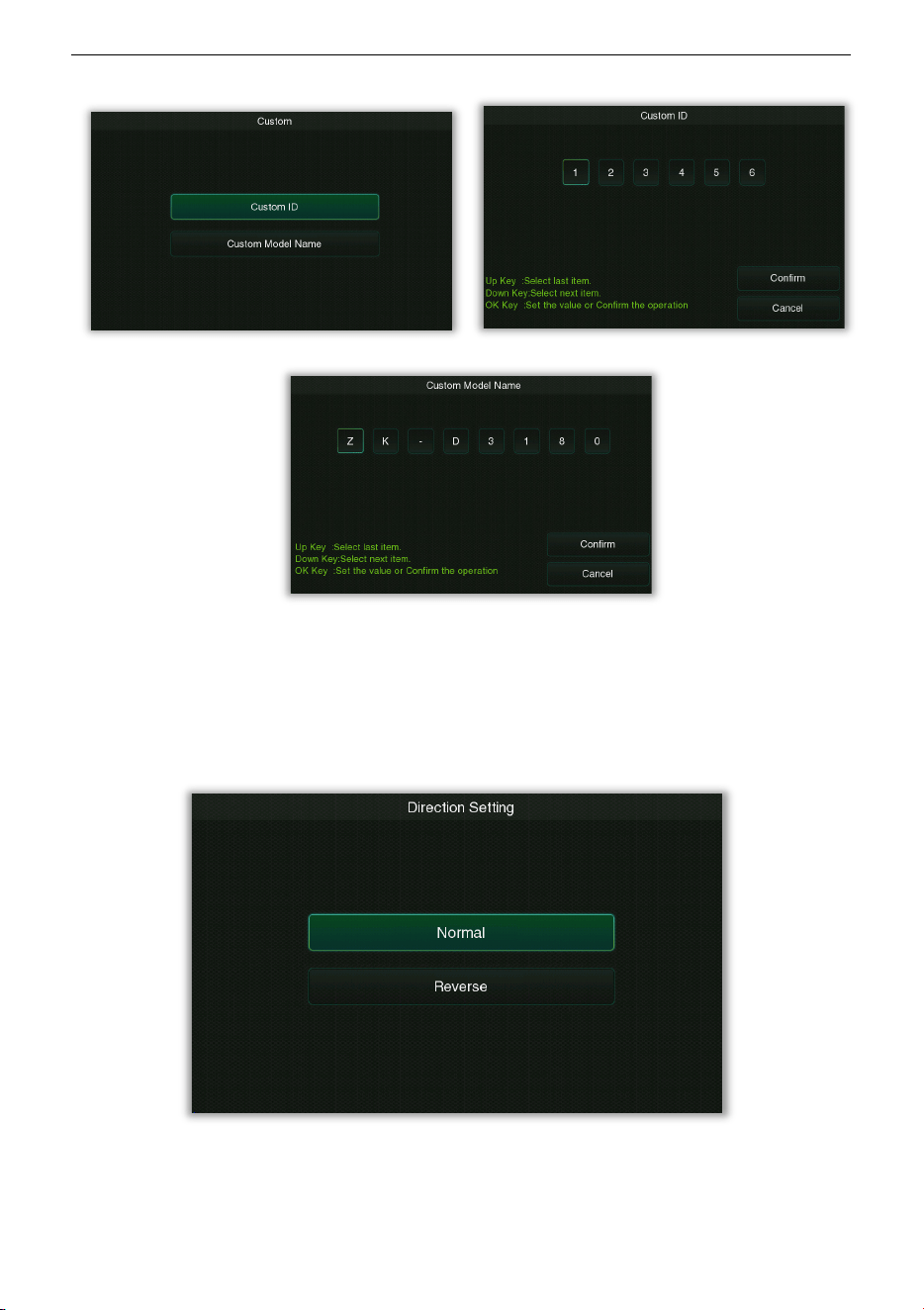
• Custom
Select Custom on the System setting interface, select Custom ID or Custom Model Name
and press OK to enter the setting interface, as shown in the following:
ZK-D3180 User Manual
Copyright©2025 ZKTECO CO., LTD. All rights reserved.
Page | 40
The ID is the device ID (the default value is 123456).
• Direction Setting
Select Direction Setting on the System setting interface, and press OK to enter the direction
setting interface, as shown in the following:
Users can define the direction of entry and exit as needed.
ZK-D3180 User Manual
Copyright©2025 ZKTECO CO., LTD. All rights reserved.
Page | 41
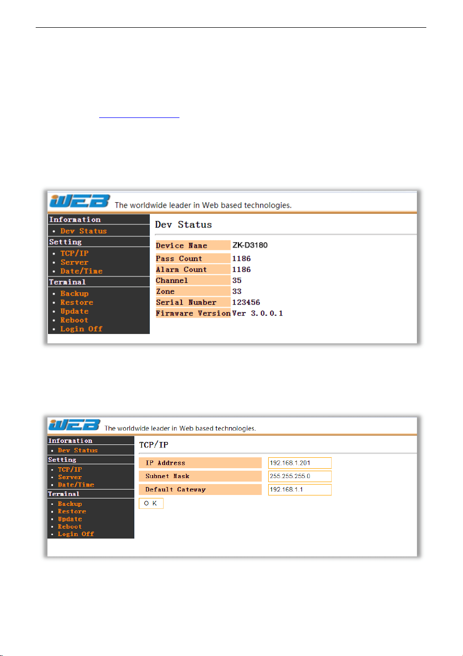
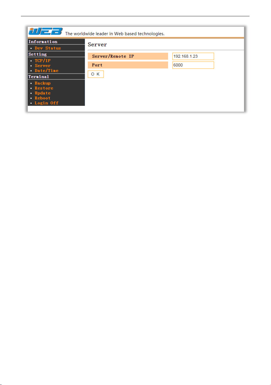
8.12 Web Server
The default IP address of the device is 192.168.1.201. You can access the Web Server through
a browser (e.g. http://192.168.1.201
).
Enter the account and password, the default account is: admin, password: admin.
After successful login, you can view the device basic information by clicking Dev Status.
Click TCP/IP to set the IP address of the device.(Note:
If you modify the IP address of the
device, then the web server link will be changed accordingly.)
Click Server to set the server address and port.
ZK-D3180 User Manual
Copyright©2025 ZKTECO CO., LTD. All rights reserved.
Page | 42

ZK-D3180 User Manual
Copyright©2025 ZKTECO CO., LTD. All rights reserved.
Page | 43
8.13 Default Parameters
Parameter Default Value
System Password
100000
Global / Zone Sensitivity 465
Channel
14
Alarm Volume 80
Alarm Delay
1.0 s
Alarm Ringtone
Ring tone 1
Random Alarm 0%
Alarm Mode
All Zone
Security Level High
Application Area
None
Screen Hibernation 120s
Language
English
Save Records
No
Detect Mode Infrared Detection Mode
Relay Mode
None
Custom ID 123456
IP Address
192.168.1.201

ZK-D3180 User Manual
Copyright©2025 ZKTECO CO., LTD. All rights reserved.
Page | 44
Troubleshooting
What to do if the Sensor could not count?
1 Check whether the host signal lines are connected firmly with the door panels.
2 Check whether there is any infrared interference beside the device, such as infrared
surveillance system, infrared remote control, outdoor sunlight, etc.
3 If both a and b are OK, replace the infrared sensor.
What to do if the detector gives a false alarm?
1 If the device gives false alarms frequently after installation, perform the following steps:
a) Firstly, check the installation environment. Make sure there are no movable or
stationary large metal objects around 1.5 meters from the detector. If there is any
metal object, try to place the device away from the large metal objects.
b) Make sure that the installation location is stable and free from physical
movements.
2 If the false alarm is not caused by the environment, reduce the sensitivity level of all
zones.
3 Change the frequency.
4 Change the installation location.

ZK-D3180 User Manual
Copyright©2025 ZKTECO CO., LTD. All rights reserved.
Page | 45
Packing List
The package consists of the following items:
No Component Quantity
1
L Side Panel 1 set
2
R Side Panel 1 set
3
Accessory Box 1 set
Accessory Box List
No Component Quantity
1
Host 1 pc
2
Adjustable Metal Bracket 1 set
3
Front Beam 1 set
4
Rear Beam 1 set
5
Power Adapter 1 set
6
Remote Control 1 pc
7
Torx Thumb Screw 2 pcs
8
Allen Screw 4 pcs
9
Hexagonal Tool 1 pc
10
Bolt 8 pcs
11
User Manual 1 pc

ZK-D3180 User Manual
Copyright©2025 ZKTECO CO., LTD. All rights reserved.
Page | 46
Warranty Card
1 Please keep this card safe and produce the same during maintenance.
2 This card will be invalid without the signature or stamp of the designated dealer.
3 This card will be regarded as invalid if the details are not filled in three guarantees
column and the acknowledgment of the receipt. Please confirm whether the data filled
in the three guarantees column and acknowledgment of receipt is correct or not when
purchasing it, and then hand it over to the dealer.
4 This card will not be issued again if it is lost.
Model Number
ID
Date of Acquisition
User
Post Code
Address
User’s Phone Number
Fax

ZK-D3180 User Manual
Copyright©2025 ZKTECO CO., LTD. All rights reserved.
Page | 47
Date of Maintenance Record of Maintenance Technician

Copyright@2025 ZKTECO CO., LTD. All rights reserved.
ZKTeco Industrial Park, No. 32, Industrial Road,
Tangxia Town, Dongguan, China.
Phone +86 769 - 82109991
Fax +86 755 - 89602394
www.zkteco.com
