54473-001
Rev 01
English / Spanish
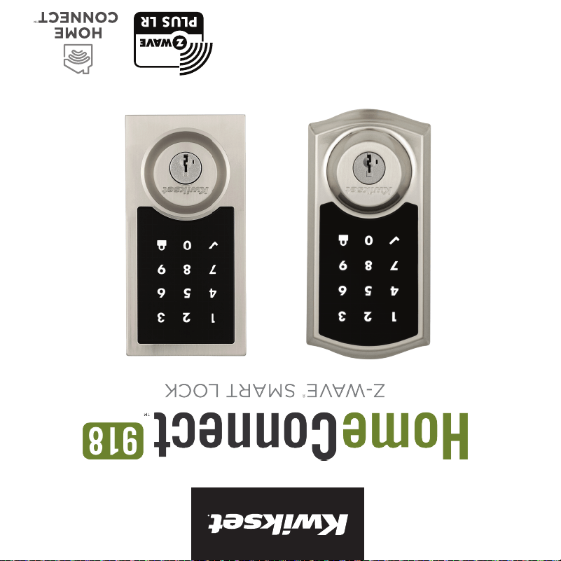
Z-Wave Plus
®
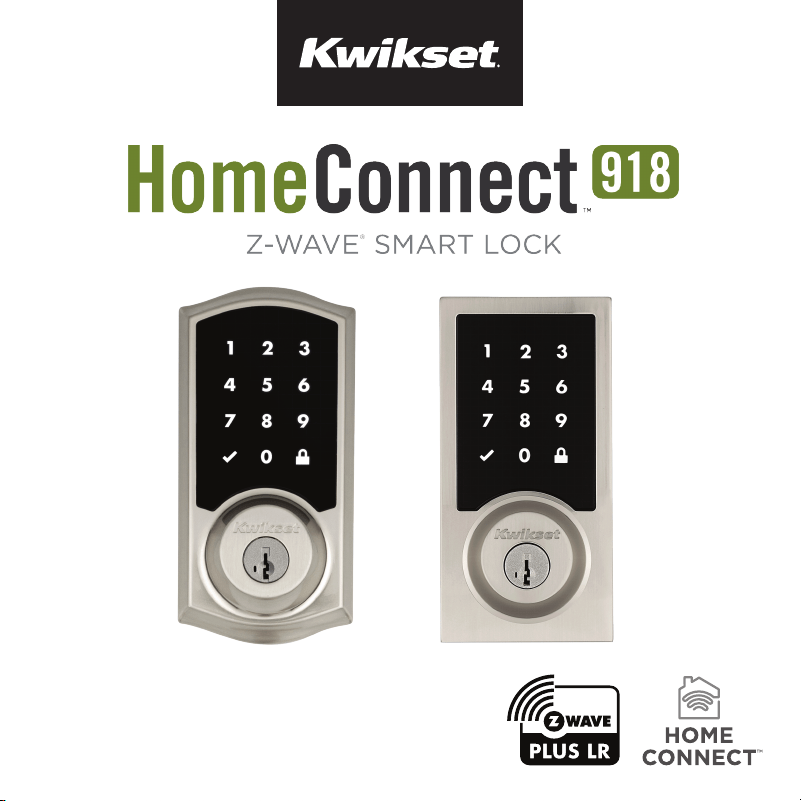
Installation Guide


Parts in the box ................................................2
Required tools ..................................................3
Installation ...........................................................5
System setup and programming.............15
Table of contents
1
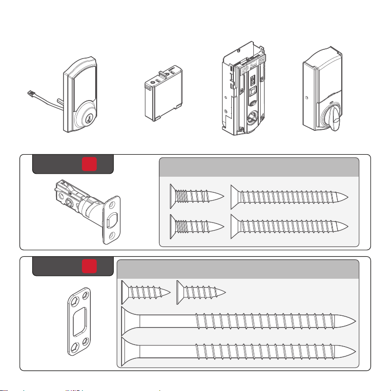
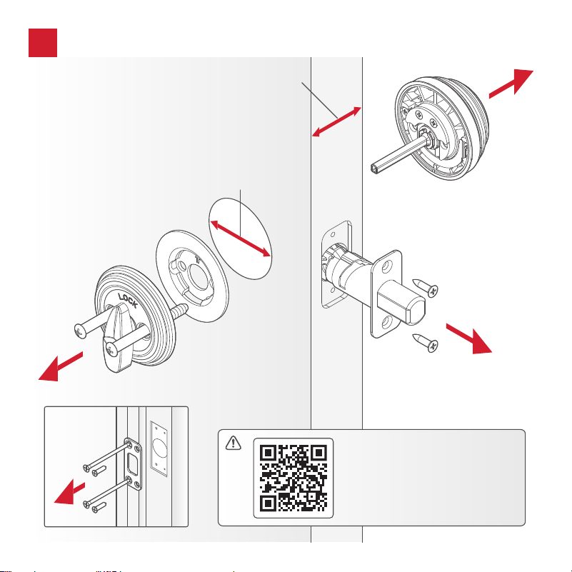
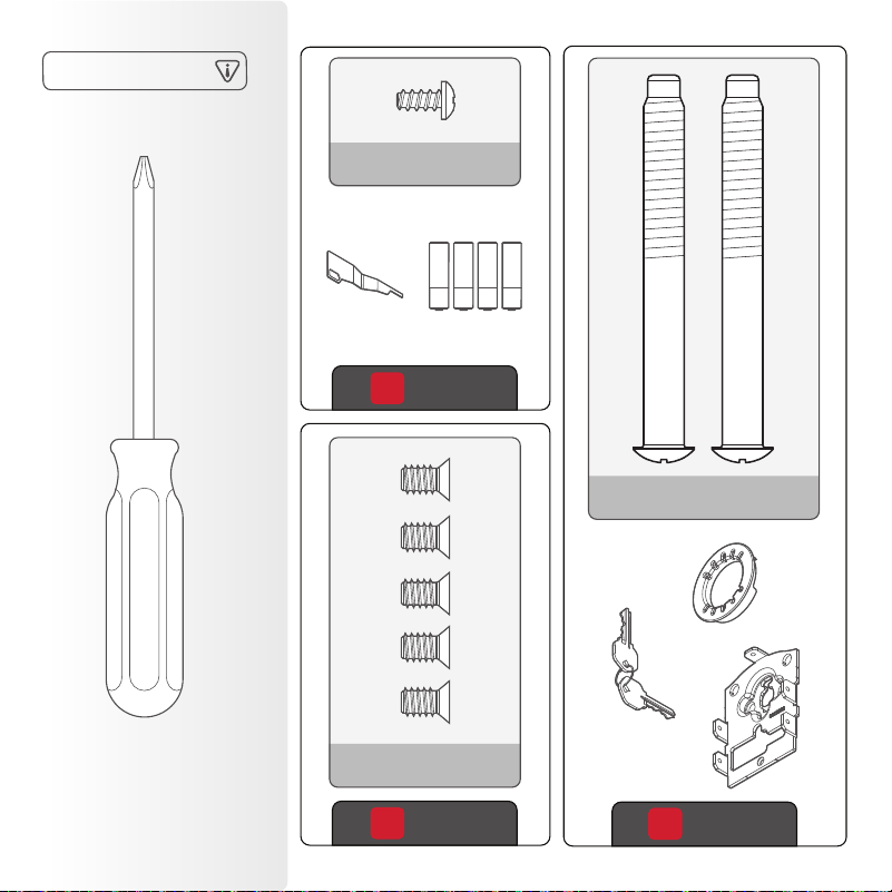
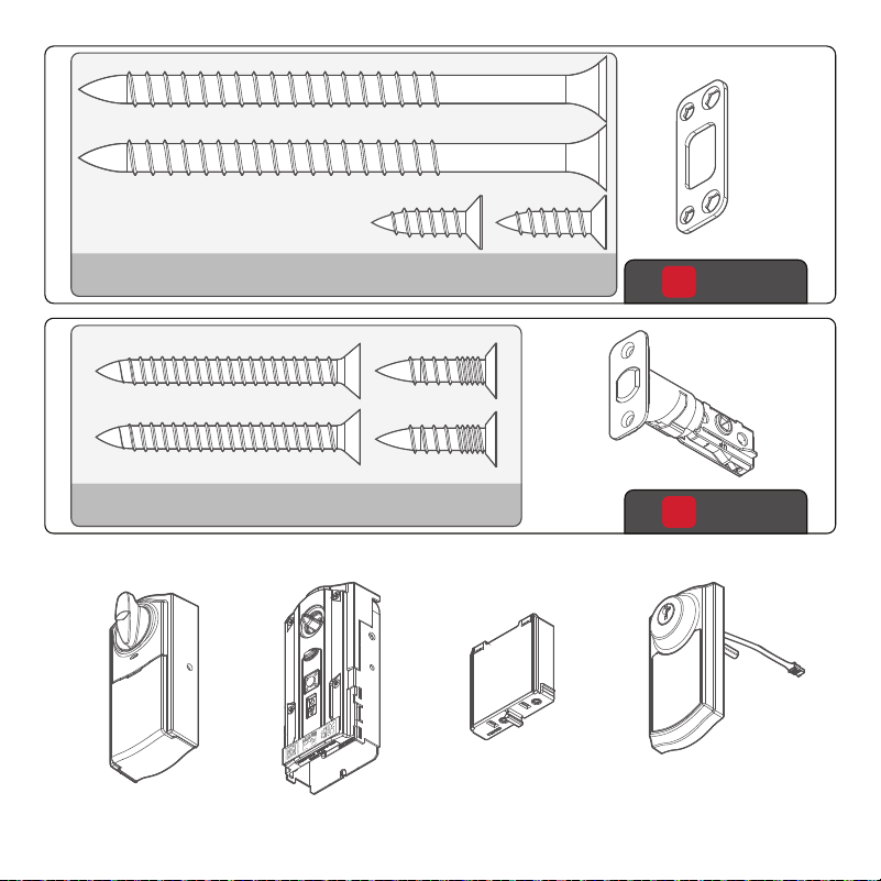
Parts in the box
Exterior assembly
Latch
Strike
Battery pack Interior assembly
Interior cover
1
Step
2
Step
actual
size
03809
46780
actual
size
2
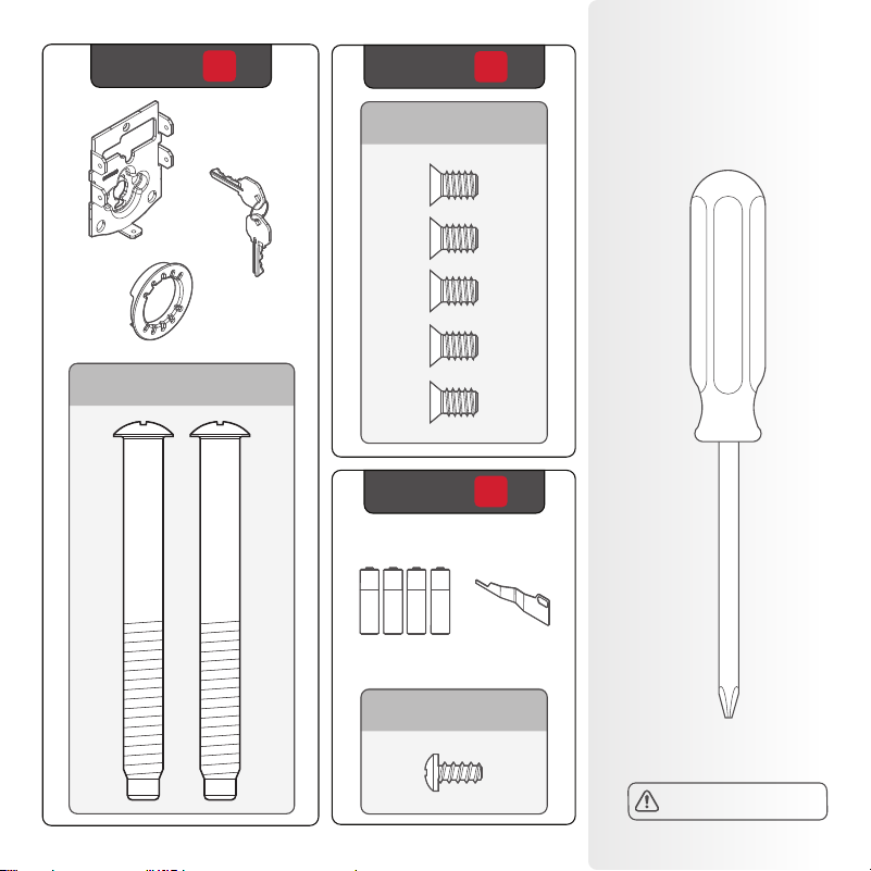
Required
tools
Mounting
plate
Adaptor
ring
Keys
Batteries
SmartKey™
tool
Phillips head
screwdriver
3
Step
4
Step
5
Step
actual
size
actual
size
actual
size
48654
69316
68611
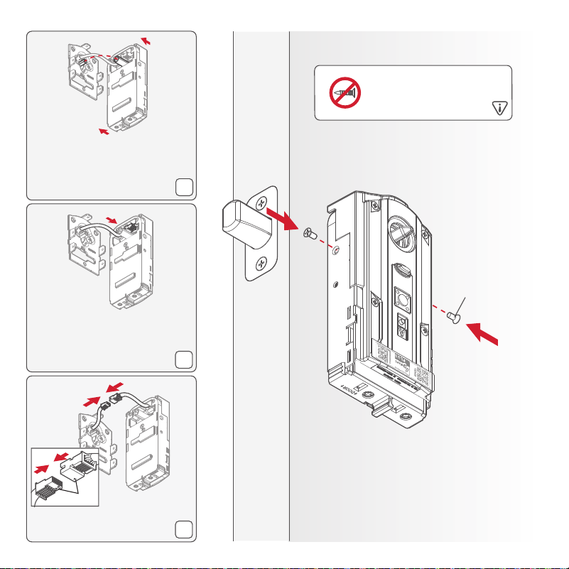
No electric drills
3

Installation
C
B
A
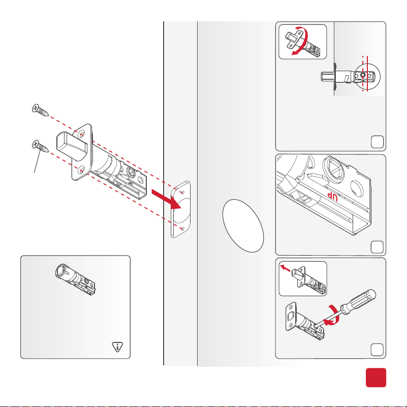
*Use the longer
screws if the holes
are worn out.
You will have two
extra screws.
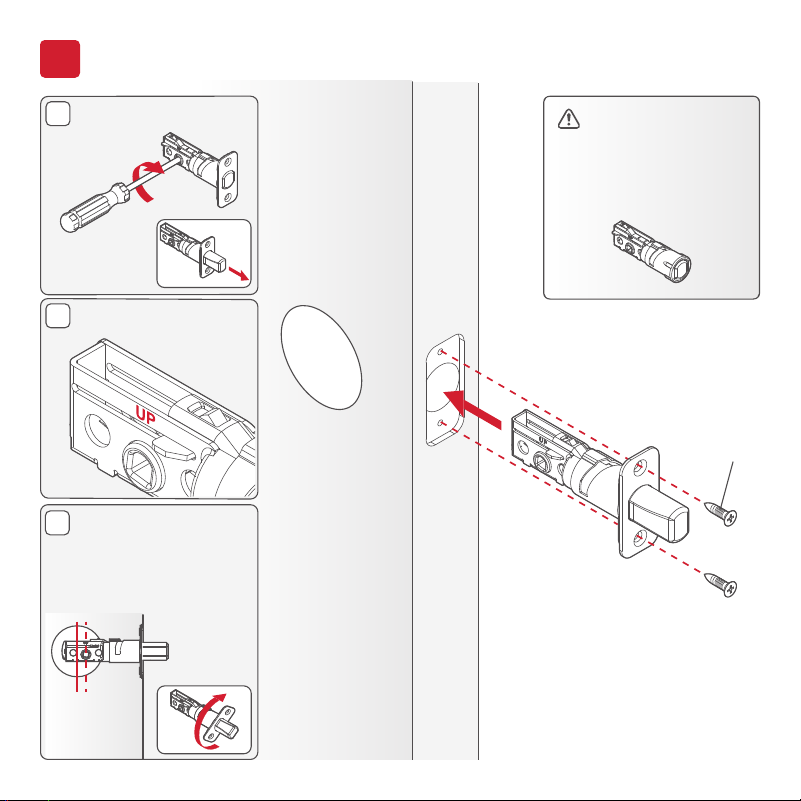
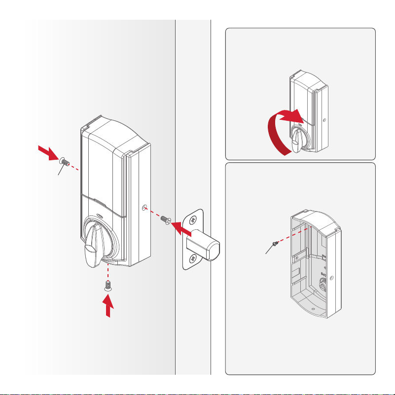
Extend the latch bolt.
UP is on top.
If the D-shaped hole
is not centered in the
door hole, rotate the
latch face to extend
the latch.
03809*
(2X)
If your door requires
a drive-in latch,
please contact
Kwikset at
1-866-863-6584.
1
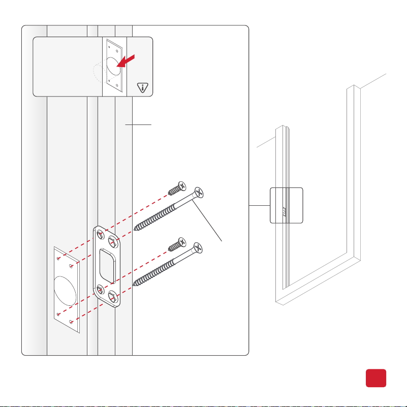
Install the latch
[OUTSIDE]
6
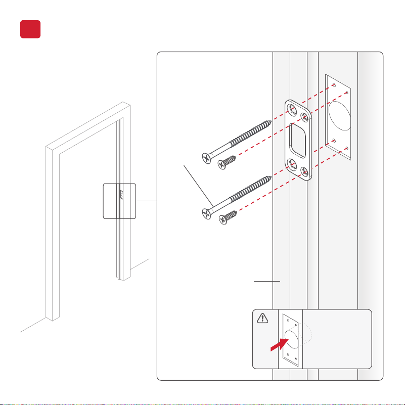
DOOR
JAMB
*Install the longer screws
closest to the door jamb.
1" (25 mm)
hole depth
46780*
(4X)
2
Install the strike
7
A
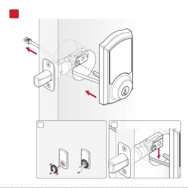
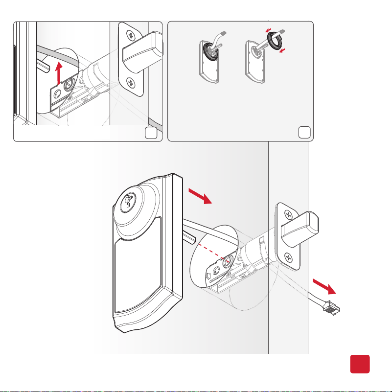
Install the exterior assembly
3
[OUTSIDE]
If the hole in the door is 2-1/8"
(54 mm), install the adapter
ring. If the hole in the door is
1-1/2" (38 mm), the adapter
ring is not needed.
8
Install the exterior assembly
Cable goes under the latch.
B
9
48654
(2x)
[INSIDE]
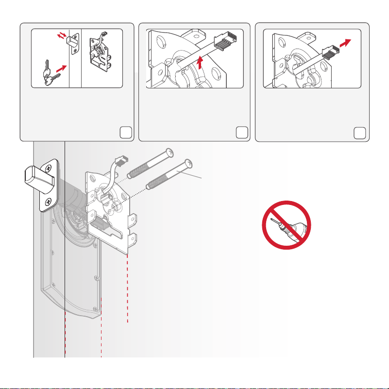
Tighten the screws evenly.
DO NOT over-tighten.
Keep parallel to
the door edge
C
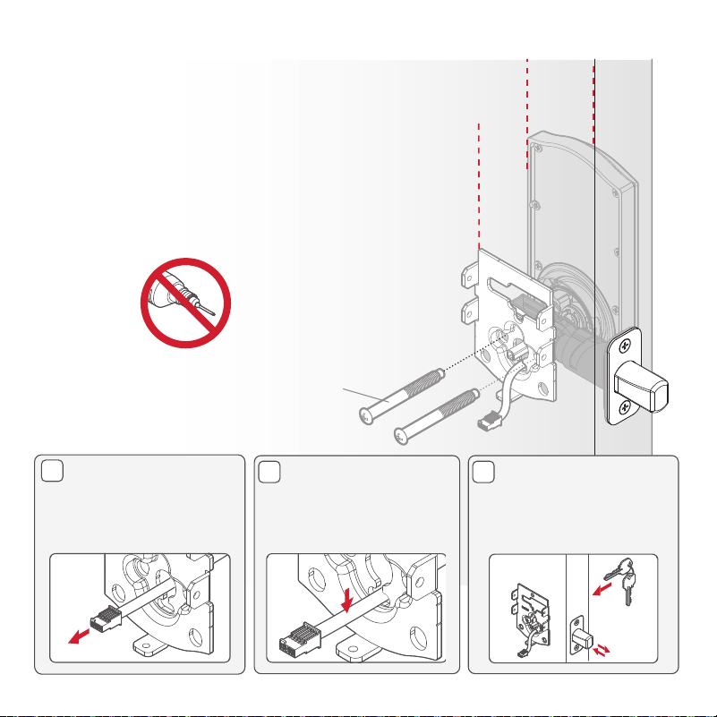
D E
Route the cable
through the center
hole of the mounting
plate.
Push the cable into
the bottom hole of
the mounting plate.
Insert the key and
test the latch. If the
latch does not extend
or retract smoothly,
adjust the screws.
B
MMMYYWWSSSSSSS
12345
WW
W
W
W
W
W
W
W
A
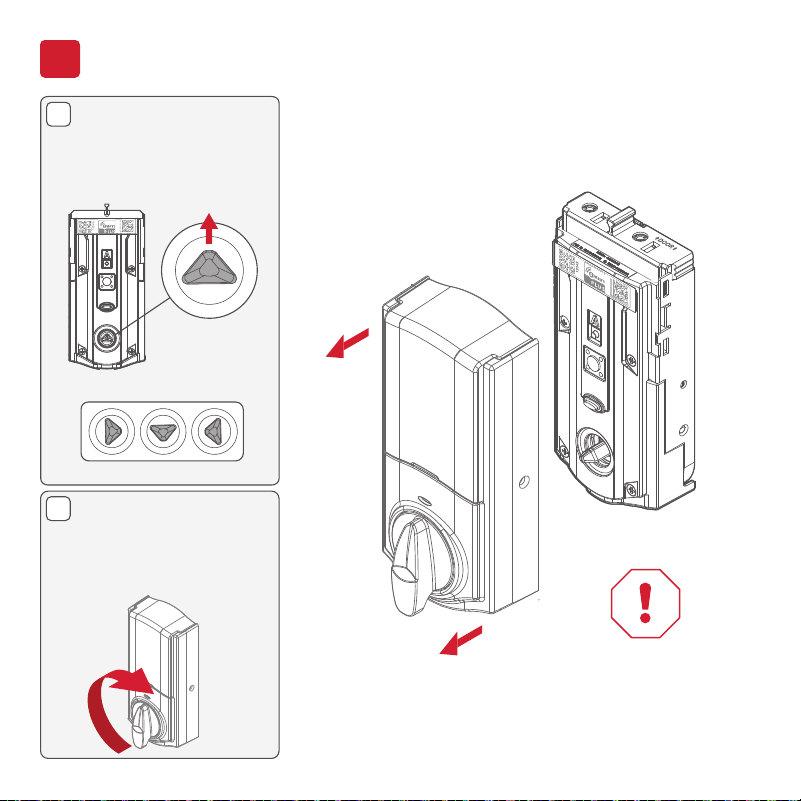
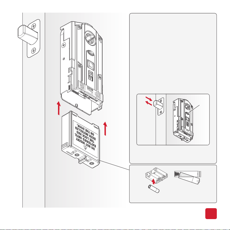
Install the interior assembly
4
Remove the interior
cover from the
interior assembly.
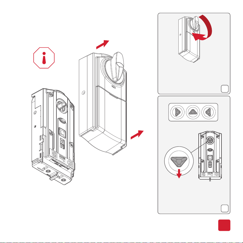
Make sure the turnpiece
shaft is pointing up as
shown below.
Incorrect:
If the turnpiece shaft
is not pointing up, put
the cover back on and
rotate the turnpiece
until you hear a click.
10
Do not install
batteries
until step 5.
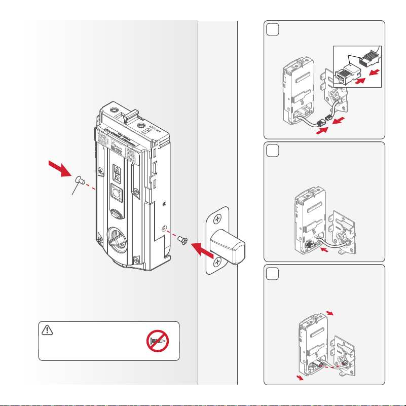
E
D
C
Secure the interior assembly
onto the mounting plate.
Note: The remaining
three screws will be
used in the next step.
69316
(2X)
Connect the cable.
Ensure a tight cable
connection.
Lay cable flat inside the
bottom of the interior
housing.
Ensure the spindle
fully engages with the
turnpiece shaft.
[INSIDE]
11
align
Ensure you are using
the correct screws.
Using incorrect screws
will damage the product.
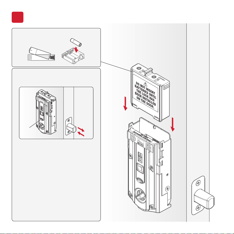
Perform the door handing process
5
With the door open, install
the battery pack to initiate
auto-handing.
NOTE: Lock
must be installed on the door
before installing the battery.
Install 4 AA batteries into the battery pack.
The latch will retract and extend to learn
the orientation of the door. Then the
status LED will indicate success or failure.
GREEN: Successful. Proceed to the
next step.
RED: Unsuccessful. Make sure the
lock interior and batteries are
correctly installed. Perform
step 5 again. If your second
attempt is still unsuccessful,
follow the Manual Door
Handing instructions on
page 19.
NOTE: The lock will auto-hand again
after the first time the door
is locked or unlocked using
the keypad or app. This is to
confirm the door orientation.
[INSIDE]
12
Status
LED
13
Secure the interior
cover onto the
interior assembly.
You may need to rotate the
turnpiece to align with the
turnpiece shaft.
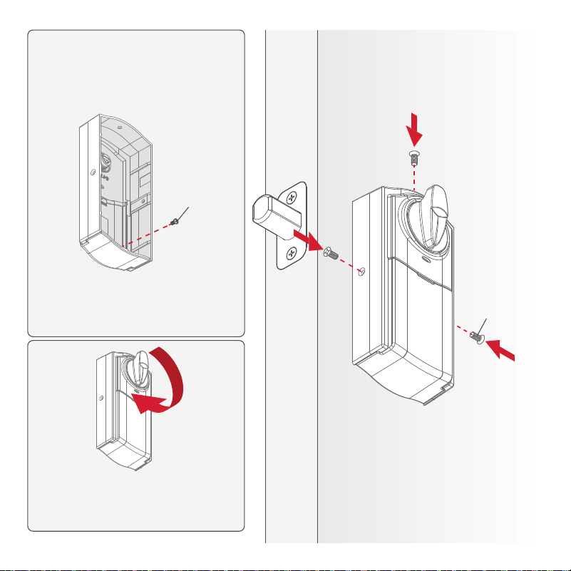
For additional security, you may
choose to lock the window by
installing the security screw.
When the window is locked, you
will need to remove the entire
cover to access the battery pack
and buttons.
69316
(3X)
68611
(1X)
[INSIDE]

System Setup
and Programming
MMMYYWWSSSSSSS
12345
WWWWWWWWW
A B
C D
MMMYYWWSSSSSSS
12345
WWWWWWWWW
MMMYYWWSSSSSSS
12345
WWWWWWWWW
PIN: 12345
15
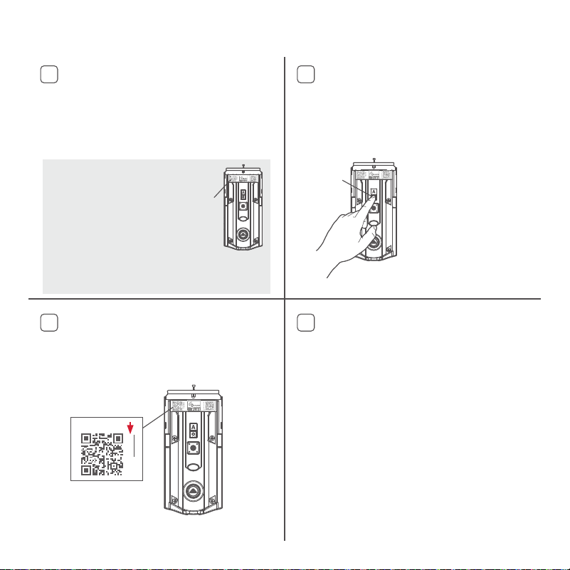
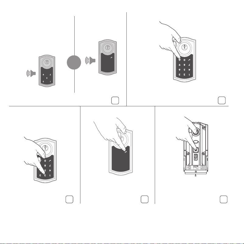
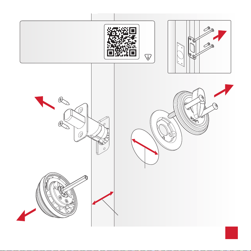
Add the lock to your smart home system
Initiate the process to add the lock to
your system at your smart home
controller. Refer to your smart home
system instructions for more information.
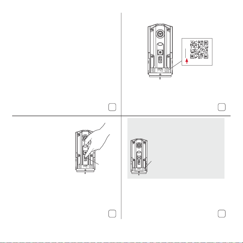
To provision the lock for Z-Wave Long
Range (LR), the SmartStart QR code
must be used.
SmartStart Enabled Products
SmartStart enabled products
can be added into a Z-Wave
network by scanning the
Z-Wave QR Code present on
the product with a controller
providing SmartStart inclusion.
No further action is required
and the SmartStart product will be
added automatically within 10 minutes of
being switched on in the network vicinity.
At this time, you may be prompted
by your smart home system to
enter the 5-digit PIN found on the
label of the interior assembly. If not,
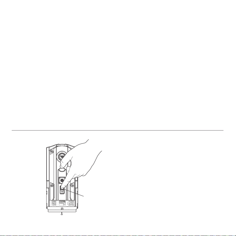
proceed to step D.
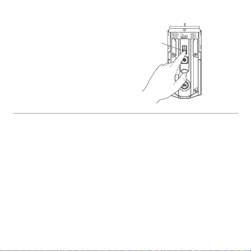
If prompted by your smart home
system to add the lock, press button
“A” on the lock interior one time.
The red LED will illuminate when the
lock enters Add Mode.
If successful, re-name the lock in
your system (if applicable).
If unsuccessful, follow your
system’s instructions to remove
the lock from the controller and
any other network, then press
button “A” on the lock one time.
Perform steps A-C again.
If still unsuccessful, consult the
Programming and Troubleshooting
Guide on the Home Connect 918
page at kwikset.com/support.
Button
“A”
5-digit PIN
QR
code
HomeConnect 918 supports
Z-Wave Long Range (LR).
To enable LR functionality
the controller must be LR
capable, and the lock must
be provisioned using the
SmartStart QR code. Button
“A” has no function when
provisioning the lock with an
LR capable controller.
Z-Wave Long Range Provisioning
MMMYYWWSSSSSSS
12345
WWWWWWWWW
A C
D E
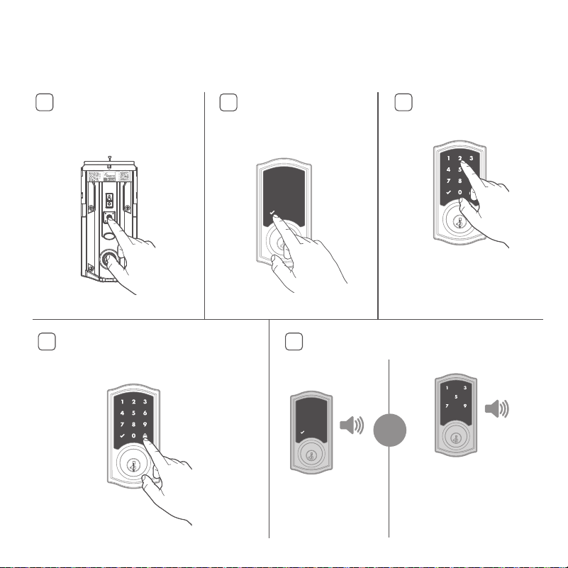
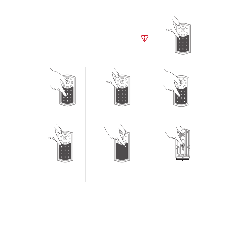
Add user codes (250 max)
Make sure the door is
open. Press the “Program”
button once.
During programming, if no button is pressed for five seconds, the system will time out,
and you will need to restart the procedure.
Enter user code. A total
of 250 users codes may
be programmed.
For security reasons, each user
code must be a unique code
between 4 and 8 digits, and the
first 4 digits of each user code
must be unique.
Press the Lock button once. What lights and sounds does the
lock produce?
16
B
Press the “Checkmark”
symbol once.
1x
Checkmark symbol
with one beep
Programming was
successful.
3x
“X” pattern with three beeps
Programming was unsuccessful.
Make sure the user code is not a
duplicate and that it is between 4 and
8 digits during your next attempt.
Make sure the lock has room for an
additional code. If all user code
positions are filled, delete a code to
make room for this one.
or
17
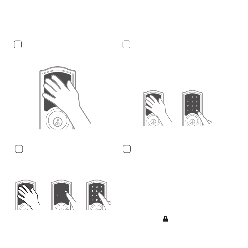
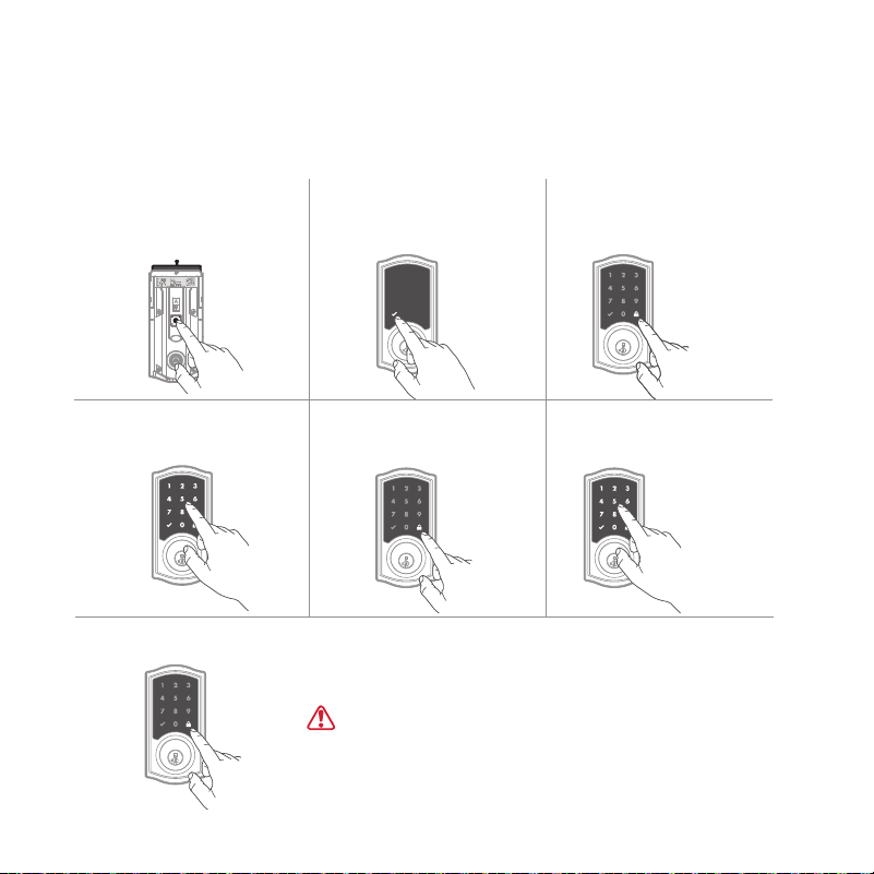
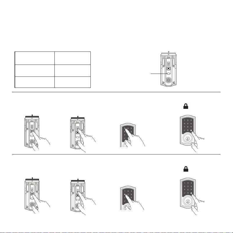
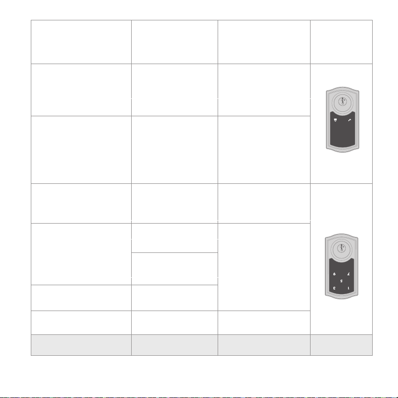
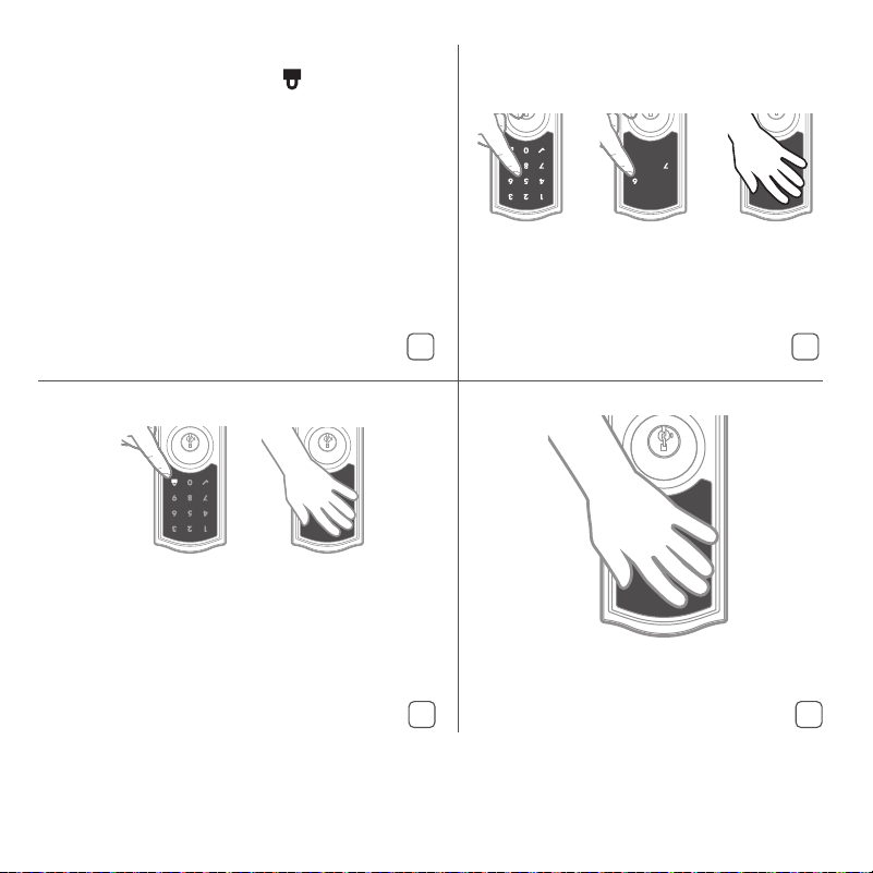
Test the lock
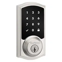
Activating the Screen
Locking the Door
Unlocking the Door
SecureScreen™
1. Activate the screen.
2. Press the "Lock" symbol.
Note: If no user codes are
programmed, the door cannot
be locked via touchscreen.
1. Activate the screen.
2. If SecureScreen™ is enabled, touch
the random digits that appear.
3. Enter user code.
If you press the wrong digit while entering a
user code, you can press the "Lock" symbol
once to clear the digits entered previously and
immediately restart the code entry proces
s.
SecureScreen™ is an added-security feature
that displays random digits before you enter
a user code. This feature ensures that there
are fingerprints on all digits so that codes
cannot be identified.
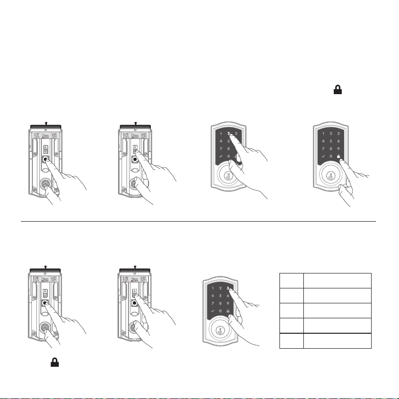
1. Press program button on the interior lock.
2. Press the “A” button on the interior lock.
3. Press the 5 button on exterior lock.
3. Press the on exterior touchscreen.
Turn SecureScreen™ On/Off
Note: This feature is turned on by default.
A B
C D
Touch screen with palm or back of hand
until digits illuminate.
Confirm that the code(s) added in previous step can unlock the door.
18
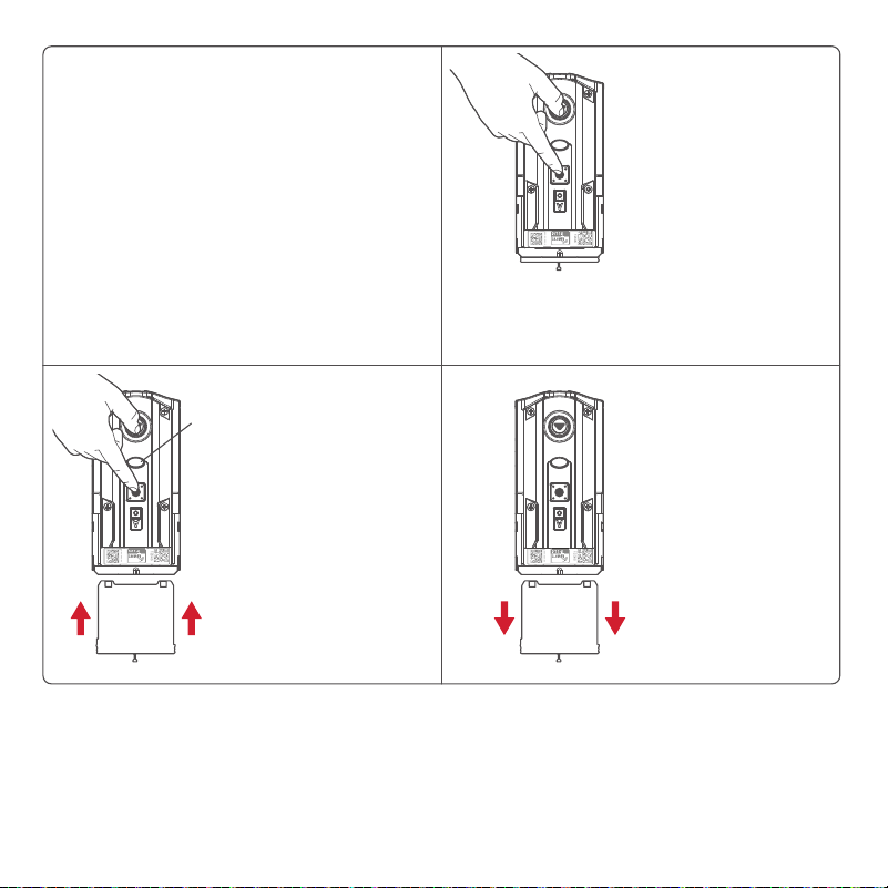
Factory reset
MMMYYWWSSSSSSS
12345
WW
W
WWWWWW
MMMYYWWSSSSSSS
12345
W
WW
W
W
W
W
W
W
MMMYYWWSSSSSSS
12345
WWWWWWWWW
A Factory Reset will delete all codes associated with the lock and the lock’s network settings
but will not remove the lock from the panel. Please run the Exclusion process to properly
remove this lock from the network before performing a Factory Reset. Please use this
procedure only when the network primary controller is missing or otherwise inoperable.
1. Remove battery
pack.
3. Press the
“Program”
button once
more. LED will
cycle flashing
between red
and green
while the reset
process is being
performed.
2. Press and HOLD
the “Program”
button while
reinserting the
battery pack.
Keep holding the
button for 30
seconds until the
lock beeps and
the status LED
flashes red.
4. After a few seconds, the lock will
initiate the door handing process,
and the latch bolt will extend and
retract to learn the orientation of
the door.
NOTE: The lock will auto-hand
again after the first time the door
is locked or unlocked using the
keypad or app. This is to confirm
the door orientation.
Status
LED
19
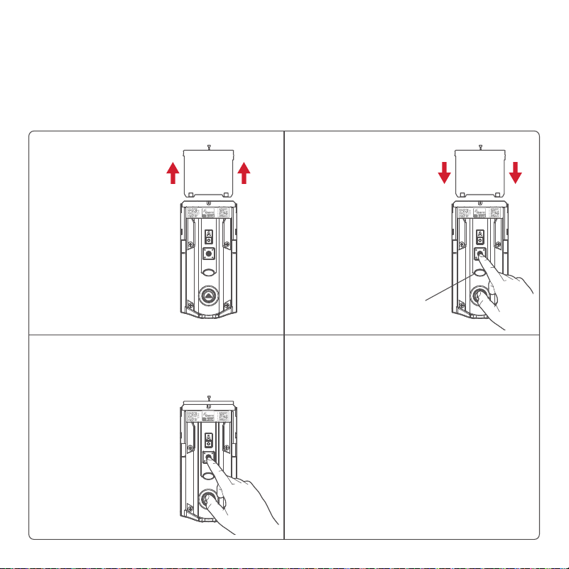
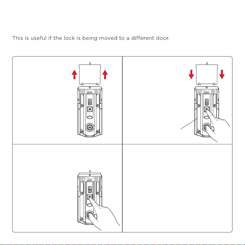
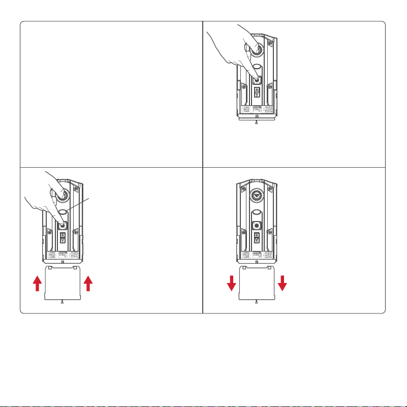
Manual Door Handing
MMMYYWWSSSSSSS
12345
WW
W
WWWWWW
MMMYYWWSSSSSSS
12345
W
WWW
WW
WW
W
MMMYYWWSSSSSSS
12345
WWWWWWWWW
If needed, the door handing process can be initiated manually.
1. Remove battery
pack.
3. Press the
“Program”
button once
more.
2. Press and HOLD
the “Program”
button while
reinserting
the battery
pack. Release
the “Program”
button after 3
seconds.
The status LED
will flash red
and green.
4. The latch bolt will extend and
retract to learn the orientation
of the door. The LED will flash
green if handing is successful or
red if handing is unsuccessful.
Status
LED
If still unsuccessful, consult the
Programming and Troubleshooting
Guide on the Home Connect 918
page at kwikset.com/support.
20
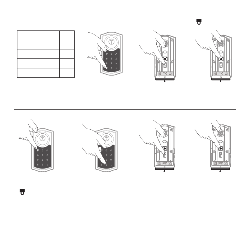
Deleting a single user code
1 Keep door open. Press
“Program” button once.
2 Press "Checkmark"
symbol once.
3 Press "Lock" symbol
once.
4 Enter user code to be
deleted.
If the screen is not pressed
for 20 seconds, the system
will time out, and you will
need to restart the
procedure.
5 Press "Lock" symbol
once.
6 Re-enter user code.
7 Press "Lock" symbol
once.
If unsuccessful
Make sure to enter the same
valid code in steps 4 and 6.
Test code
While the door is open, test
the user code to make sure it
no longer unlocks the door.
M
M
M
Y
Y
W
W
S
S
S
S
S
S
S
1234
5
W
W
W
W
W
W
W
W
W
M
M
Note: All codes may be deleted at once if the programming code is enabled.
For more information about the programming code, consult the online
Programming and Troubleshooting Guide.
21
1 Press "Program"
button once.
2 Press button “A” once.
3 Press button “2” multiple
times if needed to reach
desired state.
4 Press button
once.
Turn Auto-Lock On/Off
Auto-Lock
Auto-Lock automatically re-locks the door after unlocking.
M
M
M
Y
Y
W
W
S
S
S
S
S
S
S
1234
5
W
W
W
W
W
W
W
W
W
M
M
M
M
M
Y
Y
W
W
S
S
S
S
S
S
S
1234
5
W
W
W
W
W
W
W
W
W
M
M
1 30 sec.
2 60 sec. (1 min.)
3 180 sec. (3 min.)
4 300 sec. (5 min.)
5 600 sec. (10 min.)
1 Press "Program"
button once.
2 Press button “A”
once.
M
M
M
Y
Y
W
W
S
S
S
S
S
S
S
1234
5
W
W
W
W
W
W
W
W
W
M
M
M
M
M
Y
Y
W
W
S
S
S
S
S
S
S
1234
5
W
W
W
W
W
W
W
W
W
M
M
Change Auto-Lock Time Delay
3 Press button “3”
once.
4 Press numeric button
once that corresponds
to the desired time delay.
5 Press button once.
22
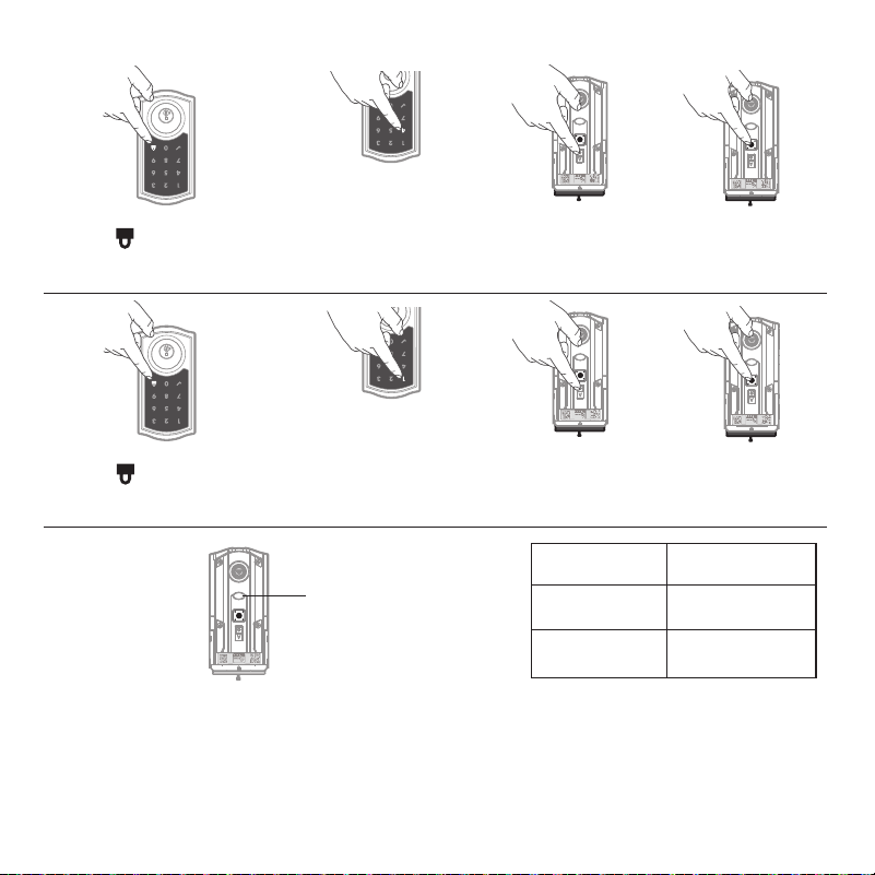
The Status LED blinks every 6 seconds to communicate whether the door is locked or unlocked.
This feature is on by default.
Status LED Colors
Blinking Green Unlocked
Blinking Amber Locked
Blinking Red Low battery
M
M
M
Y
Y
W
W
S
S
S
S
S
S
S
1
2345
W
W
W
W
W
W
W
W
W
M
M
Status
LED
1 Press "Program"
button once.
2 Press button
“A” once.
4 Press button once.
3 Press button “1”
multiple times if needed
to reach desired state.
Turn Status LED On/Off
Status LED and Audio
M
M
M
Y
Y
W
W
S
S
S
S
S
S
S
1234
5
W
W
W
W
W
W
W
W
W
M
M
M
M
M
Y
Y
W
W
S
S
S
S
S
S
S
1234
5
W
W
W
W
W
W
W
W
W
M
M
Mute/Unmute Audio (Audio is on by default)
1 Press "Program"
button once.
2 Press button
“A” once.
4 Press button once.
3 Press button “4”
multiple times if needed
to reach desired state.
M
M
M
Y
Y
W
W
S
S
S
S
S
S
S
1234
5
W
W
W
W
W
W
W
W
W
M
M
M
M
M
Y
Y
W
W
S
S
S
S
S
S
S
1234
5
W
W
W
W
W
W
W
W
W
M
M
23
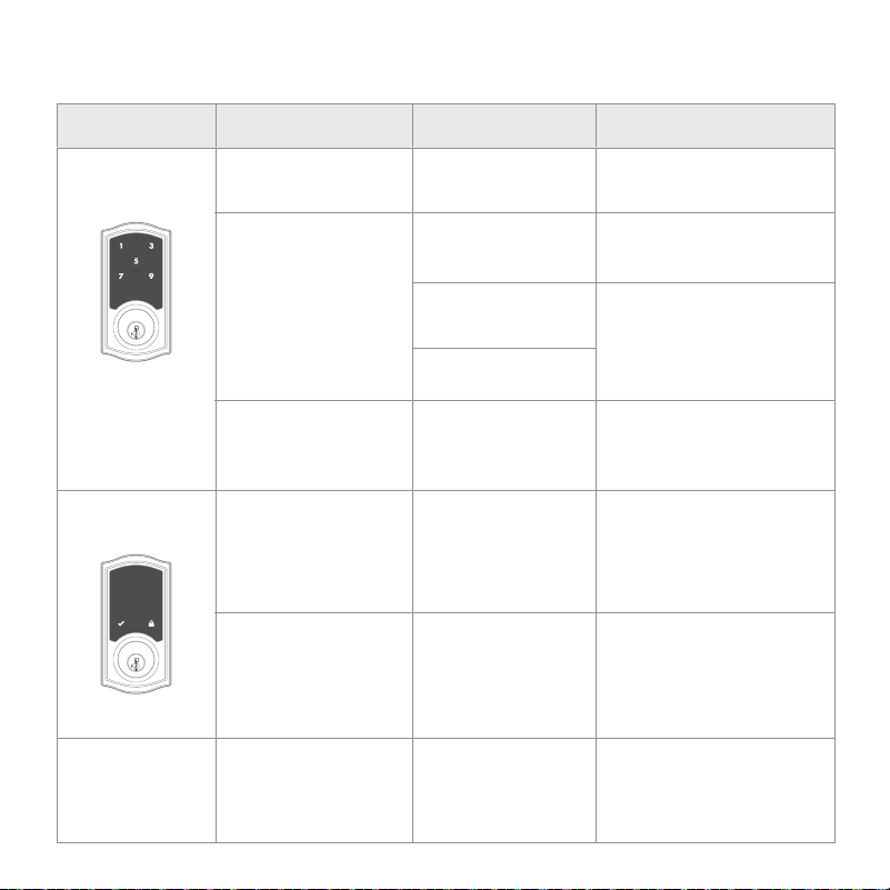
Display Alert Reason Solution
“X” pattern flashes 1
time with 1 beep*.
One incorrect code
entered.
Re-enter code.
No user code
programmed.
Program at least 1 user
code.
Programming timeout
after 20 seconds.
Attempt programming
procedure again.
Unsuccessful
programming.
3 incorrect codes
entered within 1
minute.
Re-enter code after 60
seconds of touchscreen
lockout.
Low battery. Replace batteries.
Door jammed while
attempting to lock.
Manually re-lock door. If
needed, reposition strike.
N/A
Lock beeps
continuously.
Interior assembly is
disconnected from
exterior.
Remove battery pack,
reconnect the interior to the
exterior, then replace the
battery pack.
“X” pattern flashes
3 times with 3 beeps*.
“X” pattern flashes
15 times with 15
beeps*.
Checkmark and lock
symbols flash simul-
taneously 5 times with
a long continuous
beep*.
Checkmark and lock
symbols atlternative-
ly flashes 5 times with
a long continuous
beep*.
System Alerts
MMMYYWWSSSSSSS
12345
WWWW
W
WWWW
24
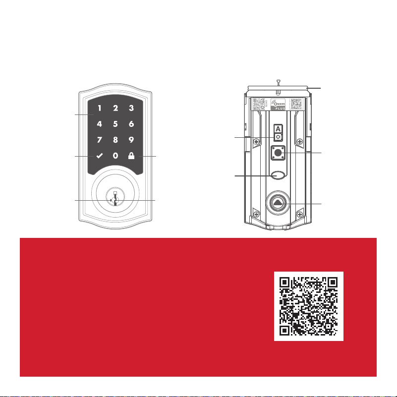
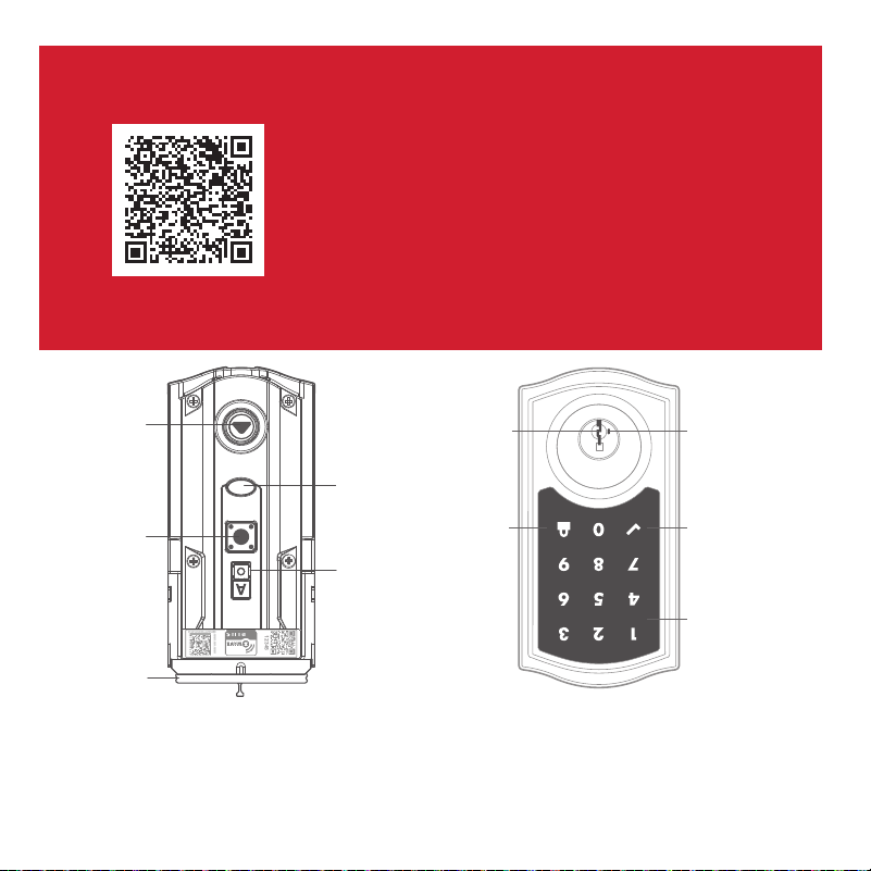
HomeConnect 918 at a Glance
Exterior Interior
(cover removed)
Button “A”
Status LED
“Program”
button
Turnpiece
shaft
Battery
pack
Troubleshooting
If you have any issues, please visit our
support center: kwikset.com/support
or call us at 1-866-863-6584.
Touchscreen
"Checkmark"
symbol
"Lock"
symbol
Keyway
SmartKey
tool hole
MMMYYWWSSSSSSS
12345
WWWWWWWWW
Network Information
Z-Wave® System Notes
Removing the lock from the network
Follow your smart home system’s
instructions to remove the lock from
the network. When prompted by the
system, press button “A” on the lock
interior once.
This product is a security enabled Z-Wave Plus product and must be used
with a Security Enabled Z-Wave controller to be fully utilized. Z-Wave
is a “Wireless mesh network,” and results may vary based on building
construction and communication path.
To assure interoperability, each Z-Wave product must pass a stringent
conformance test to assure that it meets the Z-Wave standard for complete
compliance with all other devices and controls. The Z-Wave identity mark
assures consumers, integrators, dealers and manufacturers that their
products will reliably perform with any other Z-Wave device. And, regardless
of the vendor, always powered nodes may act as a repeater for Kwikset/
Weiser/Baldwin products.
Z-Wave Configuration and Association Parameters are available on the
HomeConnect 918 page at www.kwikset.com.
Button
“A”
25

26
Important Safeguards
Regulatory Compliance
1. Read all instructions in their entirety.
2. Familiarize yourself with all warning and
caution statements.
3. Remind all family members of
safety precautions.
4. Always have access to your lock’s
standard key.
5. If using the Auto-Lock features, make sure you
have your smartphone or standard key with you
to prevent locking yourself out.
6. Familiarize yourself with all error notifications.
7. Replace low batteries immediately.
8. Dispose of used batteries according to local
laws and regulations.
WARNING: This Manufacturer advises that no lock can provide complete security by itself. This lock may be defeated by
forcible or technical means, or evaded by entry elsewhere on the property. No lock can substitute for caution, awareness of
your environment, and common sense. Builder’s hardware is available in multiple performance grades to suit the application. In
order to enhance security and reduce risk, you should consult a qualified locksmith or other security professional.
This product complies with
standards established by the
following regulatory bodies:
Federal Communications
Commission (FCC)
• Industry Canada
FCC
This device complies with Part
15 of the FCC Rules. Operation
is subject to the following two
conditions: (1) this device may
not cause harmful interference,
and (2) this device must accept
any interference received,
including interference that
may cause undesired operation.
This equipment has been tested
and found to comply with the
limits for a Class B digital device,
pursuant to Part 15 of the FCC
Rules. These limits are designed
to provide reasonable protection
against harmful interference in a
residential installation. This
equipment generates, uses, and can
radiate radio frequency energy and,
if not installed and used in
accordance with the instructions,
may cause harmful interference to
radio communications. However, t
here is no guarantee that
interference will not occur in a
particular installation. If this
equipment does cause harmful
interference to radio or television
reception, which can be determined
by turning the equipment o and on,
the user is encouraged to try to
correct the interference by
one or more of the following
measures:
• Reorient or relocate the receiving
antenna.
• Increase the separation between
the equipment and receiver.
IMPORTANT! Changes or
modifications not expressly
approved by the manufacturer
could void the user’s authority to
operate the equipment.
Industry Canada
This devices contains licence-
exempt transmitter(s)/receiver(s)
that comply with Innovation,
Science and Economic Development
Canada’s licence-exempt RSS(s).
Operation is subject to the following
two conditions: (1) This device may
not cause interference. (2) This
device must accept any interference,
including interference that may
cause undesired operation of the
device.
•
• Connect the equipment into an
outlet on a circuit dierent from
that to which the receiver is
connected.
• Consult the dealer or an
experienced radio/TV technician
for help.
Copyright © 2024 ASSA ABLOY Americas Residential Inc. All rights reserved

26
Medidas de protección importantes
Cumplimiento Normativo
1. Lea todas las instrucciones en su totalidad.
2. Familiarícese con todas las declaraciones de
advertencia y precaución.
3. Recuerde a todos los miembros de la familia las
precauciones de seguridad.
4. Siempre tenga acceso a la llave estándar de su
cerradura.
5. Si usa las funciones de bloqueo automático,
asegúrese de tener su teléfono inteligente o
llave estándar para evitar bloquearse.
6. Familiarícese con todas las notificaciones de
error de la barra de luces.
7. Reemplace las baterías bajas de inmediato.
8. Deseche las baterías usadas de acuerdo con las
leyes y regulaciones locales.
ADVERTENCIA: Este Fabricante hace saber que no hay cerrojos que puedan proporcionar completa seguridad por sí
mismos. Puede hacerse que falle este cerrojo forzándolo o utilizando medios técnicos, o puede evadirse entrando por otra parte
de la propiedad. No hay cerrojos que puedan hacer de sustitutos para la precaución, el estar al tanto del entorno, y el sentido
común. Pueden obtenerse piezas de ferretería de constructor con diversos grados de rendimiento para ajustarse a la aplicación.
Para realzar la seguridad y reducir los riesgos, debe consultar con un cerrajero capacitado u otro profesional de seguridad.
Este producto cumple con el
estándar establecido por los
siguientes entes regulatorios:
Federal Communications
Commission (FCC)
•
Industry Canada
FCC
Este dispositivo cumple con
Parte 15 de las Reglas de la FCC.
La operación está sujeta a la
siguientes dos condiciones: (1) Es
posible que este dispositivo no
cause interferencia perjudicial, y
(2) Este dispositivo debe aceptar
cualquier interferencia recibida,
incluidas las interferencias que
puede causar causas no deseadas
operación. Este equipo ha sido
probado y encontrado para
cumplir con los límites de un
dispositivo digital de clase B,
de conformidad con la parte
15 de la Reglas de la FCC.
Estos límites están diseñados
para proporcionar una
protección razonable contra
interferencias dañinas en una
instalación residencial.Éste equipos
generan, utilizan, y puede irradiar
radiofrecuencia energía y, si no está
instalada y utilizado de conformidad
con el instrucciones, puede causar
daños Interferencias a la radio
comunicaciones. Sin embargo,
no hay garantía de que no se
produzcan interferencias en una
una instalación en particular. Si
este el equipo causa daños
interferencia en la recepción de
radio o televisión, que se puede
determinar apagando y
encendiendo el equipo, else
anima al usuario a intentar
corrija la interferencia uno o
más de los siguientes medidas:
• Reoriente o reubique la
antena receptora.
• Aumentar la separación entre
el equipo y el receptor.
¡IMPORTANTE! Cambios o
Modificaciones no aprobadas
expresamente por parte del
fabricante podría anular la autoridad
del usuario para operar el equipo.
Industry Canada
Este dispositivo contiene
Transmisor(es)/receptor(es)
exento(s) que cumplen con la
Innovación, RSS(s) exentos de
licencia del Ministerio de Ciencia
y Desarrollo Económico del
Canadá. El funcionamiento está
sujeto a las dos condiciones
siguientes: (1) Este dispositivo
puedeno causar interferencias.
(2) Este el dispositivo debe
aceptar cualquier interferencia,
incluidas las interferencias que
puedan causar un funcionamiento
no deseado del dispositivo.
•
• Conecte el equipo a un
circuito diferente al receptor.
• Consulte al distribuidor o a un
técnico experimentado de radio/
TV para obtener.
Copyright © 2024 ASSA ABLOY Americas Residential Inc. All rights reserved
MMMYYWWSSSSSSS
12345
WWWWWWWWW
Información de red
Notas del sistema Z-Wave
Retirando la cerradura de la red
Siga las instrucciones de su sistema
de hogar inteligente para quitar el
candado de la red. Cuando se lo solicite
el sistema, presione el botón “A” en el
interior de la cerradura una vez.
Este producto es un producto Z-Wave Plus habilitado para seguridad y
debe usarse con un controlador Z-Wave habilitado para seguridad para
ser utilizado por completo. Z-Wave es una “red de malla inalámbrica” y
los resultados pueden variar según la construcción del edificio y la ruta
de comunicación.
Para garantizar la interoperabilidad, cada producto Z-Wave debe pasar
una estricta prueba de conformidad para garantizar que cumple con
el estándar Z-Wave para el cumplimiento total de todos los demás
dispositivos y controles. La marca de identidad Z-Wave asegura a los
consumidores, integradores, distribuidores y fabricantes que sus productos
funcionarán de manera confiable con cualquier otro dispositivo Z-Wave. Y,
independientemente del proveedor, los nodos siempre alimentados pueden
actuar como repetidores para los productos Kwikset / Weiser / Baldwin.
Los parámetros de asociación y configuración de Z-Wave están disponibles
en la página de HomeConnect 918 en www.kwikset.com .
Botón
“A”
25
MMMYYWWSSSSSSS
12345
WWWWWWWWW
HomeConnect 918 de un vistazo
Exterior Interior
(sin tapa)
Botón “A”
Estado
del LED
Botón de
“Programa”
Eje de
la perilla
Conjunto
de baterias
Solución de problemas
Si tiene algún problema, visite nuestro
centro de soporte: kwikset.com/support
o llámenos al 1-866-863-6584.
24
Pantalla táctil
Símbolo de
«bloqueo
Chavetero
Orificio de la
herramienta
Smartkey
™
Símbolo de «marca
de verificación
«
«
23
Alertas del sistema
Monitor Alerta Razón Solución
El patrón "X" parpadea
1 vez con 1 pitido*.
Ingreso de código
incorrecto.
Vuelva a ingresar el código.
Sin código de usuario
Programado.
Programar al menos 1
código de usuario.
Tiempo de espera de
programación después
de 20 segundos.
Intente de nuevo el
procedimiento de
programación.
Falla de
programación.
3 códigos incorrectos
ingresados dentro de 1
minuto.
Vuelva a ingresar el código
después de 60 segundos de
que la pantalla táctil se apague.
Batería baja. Reemplace las baterías.
La puerta se atascó
al intentar cerrarla.
Intente bloquear
manualmente la puerta.
Si es necesario ajuste el
pestillo.
N/A
Pitidos de bloqueo
continuos.
El ensamble interior
esta desconectado del
ensamble exterior.
Retire la caja de baterías,
vuelva a conectar el interior
al exterior, luego reemplace
el batería.
El patrón "X" parpadea
3 veces con 3 pitidos*.
El patrón "X" parpadea
15 veces con 15
Pitidos*.
Los símbolos de "marca
de verificación" y
"Bloqueo" parpadean
simultáneamente
taneamente 5 veces con
un largo pitido continuo*.
Los símbolos de "marca
de verificación" y
"Bloqueo" parpadean
junto con un pitido
continuo*.
22
El LED de estado parpadea cada 6 segundos para comunicar si la puerta está bloqueada o
desbloqueada. Esta función está activada por defecto.
Colores del LED de estado
Verde intermitente Desbloqueado
Ámbar intermitente Bloqueado
Rojo intermitente Batería baja
M
M
M
Y
Y
W
W
S
S
S
S
S
S
S
1
2345
W
W
W
W
W
W
W
W
W
M
M
LED de
estado
1 Pulse una vez el
botón «Programar».
2 Pulse una vez el
botón «A».
4 Pulse el botón .
3 Pulse el botón «1»
varias veces si es
necesario para alcanzar
el estado deseado.
Encender/Apagar el LED de estado
LED de estado y audio
M
M
M
Y
Y
W
W
S
S
S
S
S
S
S
1234
5
W
W
W
W
W
W
W
W
W
M
M
M
M
M
Y
Y
W
W
S
S
S
S
S
S
S
1234
5
W
W
W
W
W
W
W
W
W
M
M
Mute/Unmute Audio (Audio is on by default)
1 Pulse una vez el
botón «Programar».
2 Pulse una vez el
botón «A».
4 Pulse el botón .
3 Pulse el botón «4»
varias veces si es
necesario para alcanzar
el estado deseado.
M
M
M
Y
Y
W
W
S
S
S
S
S
S
S
1234
5
W
W
W
W
W
W
W
W
W
M
M
M
M
M
Y
Y
W
W
S
S
S
S
S
S
S
1234
5
W
W
W
W
W
W
W
W
W
M
M
21
1 Pulse una vez el
botón «Programar».
2 Pulse una vez el
botón «A».
3 Pulse el botón «2» varias
veces si es necesario para
alcanzar el estado deseado.
4 Pulse el botón .
Activar/Desactivar el bloqueo automático
Bloqueo Automático
Bloqueo automático vuelve a bloquear automáticamente la puerta después
de desbloquearla.
M
M
M
Y
Y
W
W
S
S
S
S
S
S
S
1234
5
W
W
W
W
W
W
W
W
W
M
M
M
M
M
Y
Y
W
W
S
S
S
S
S
S
S
1234
5
W
W
W
W
W
W
W
W
W
M
M
1 30 sec.
2 60 sec. (1 min.)
3 180 sec. (3 min.)
4 300 sec. (5 min.)
5 600 sec. (10 min.)
1 Pulse una vez el
botón «Programar».
2 Pulse una vez el
botón «A».
M
M
M
Y
Y
W
W
S
S
S
S
S
S
S
1234
5
W
W
W
W
W
W
W
W
W
M
M
M
M
M
Y
Y
W
W
S
S
S
S
S
S
S
1234
5
W
W
W
W
W
W
W
W
W
M
M
Cambiar el retardo de bloqueo automático
3 Pulse el botón «3»
una vez.
4 Pulse el botón numérico
una vez el que corresponda
al tiempo de retardo deseado.
5 Pulse el botón .
20
Eliminar un código de usuario único
1 Mantenga la puerta abierta. Pulse
el botón «Programar» una vez.
2 Pulse una vez el símbolo
«Marca de verificación».
3 Pulse el símbolo «Bloqueo»
una vez.
4 Introduzca el código de
usuario que borrar.
Si no se pulsa la pantalla durante
20 segundos, el sistema se
desconectará y deberá deberá
reiniciar el procedimiento.
5 Pulse el símbolo «Bloqueo»
una vez.
6 Reintroduzca el código de
usuario.
7 Pulse el símbolo «Bloqueo»
una vez.
Si no tiene éxito
Asegúrese de introducir el
mismo código válido en los
pasos 4 y 6.
Código de prueba
Mientras la puerta está abierta,
pruebe el código de usuario
para asegurarse de que ya no
desbloquea la puerta.
M
M
M
Y
Y
W
W
S
S
S
S
S
S
S
1234
5
W
W
W
W
W
W
W
W
W
M
M
Nota: Todos los códigos pueden borrarse a la vez si el código de programación
está activado. Para más información sobre el código de programación, consulte
la Guía de programación y resolución de problemas en línea.
Orientación manual de la puerta
MMMYYWWSSSSSSS
12345
WWWWWWWW
W
MMMYYWWSSSSSSS
12345
WWWWWWWW
W
MMMYYWWSSSSSSS
12345
WWWWWWWW
W
En caso de ser necesario, el proceso de orientación de la puerta se puede iniciar
en forma manual. Esto es útil si la cerradura se retira para colocarse en una
puerta diferente.
1. Retire el conjunto
de baterías.
3. Presione el botón
“Programa”
una vez más.
2. Presione y
MANTENGA
presionado el
botón “Programa”
mientras vuelve a
insertar el conjunto
de baterias. Suelte
el botón “Programa”
después de 3
segundos. El LED de
estado parpadeará
en rojo y verde.
4. El pestillo se extenderá y retraerá
para aprender la orientación de
la puerta. El LED parpadeará en
verde si la manipulación se realiza
correctamente o en rojo si no se ha
realizado correctamente.
LED
de
estado
19
Restablecimiento de fábrica
MMMYYWWSSSSSSS
12345
WWWWWWWW
W
MMMYYWWSSSSSSS
12345
WWWWWWWW
W
MMMYYWWSSSSSSS
12345
WWWWWWWW
W
Un restablecimiento de fábrica eliminará todos los códigos asociados con el candado y
la configuración de red del candado, pero no eliminará el candado del panel. Ejecute el
proceso de exclusión para eliminar correctamente este bloqueo de la red antes de realizar
un restablecimiento de fábrica. Utilice este procedimiento solo cuando falte el controlador
primario de red o no esté operativo.
1. Retire el conjunto
de baterías.
3. Presione el botón
“Programa”
una vez más. El
LED parpadeará
cíclicamente
entre rojo y verde
mientras se realiza
el proceso de
reinicio.
2. Presione y MANTENGA
PRESIONADO el
botón “Programa”
mientras inserta el
conjunto de baterias.
Mantenga presionado
el botón durante 30
segundos hasta que
la cerradura emita un
pitido y el
LED de estado
parpadee en rojo.
4. Después de unos segundos, la
cerradura iniciará el proceso de
apertura de la puerta y el pestillo se
extenderá y ret
raerá para aprender la
orientación de la puerta.
NOTA: La cerradura se activará
automáticamente de nuevo después
de la primera vez que se bloquee o
desbloquee la puerta con el teclado o
la aplicación. Esto es para confirmar
la orientación de la puerta.
LED
de
estado
18
17
Probar la cerradura
Activar la pantalla
Cerrar la puerta
Desbloqueo de la puerta
SecureScreen™
1. Activa la pantalla.
2. Pulse el símbolo «Bloqueo».
Nota: Si no hay códigos de usuario
programados, la puerta no podrá
bloquearse a través de la pantalla
táctil.
1. Activa la pantalla.Activa la pantalla.
2. Si SecureScreen™ está activado,
toque los dígitos aleatorios que
aparecen.
3. Introduzca el código de usuario.
Si pulsa un dígito equivocado al introducir un código
de usuario, puede pulsar el símbolo «Bloqueo» una
vez para borrar los dígitos introducidos
anteriormente y reiniciar inmediatamente el proceso
de introducción del código.
SecureScreen™ es una función de seguridad
añadida que muestra dígitos aleatorios antes
de introducir un código de usuario. Esta
función garantiza que huellas dactilares en
todos los dígitos para que los códigos no
puedan ser identificados.
1. Pulse el botón de programación de la
cerradura interior.
2. Pulse el botón «A» de la cerradura interior.
3. Pulse el botón 5 de la cerradura exterior.
3. Pulse el en la pantalla táctil exterior.
Activar/Desactivar SecureScreen™
Nota: Esta función está activada por defecto.
A B
C D
Toque la pantalla con la palma o el
dorso de la mano hasta que se
iluminen los dígitos.
Confirme que el código o códigos añadidos en el paso anterior pueden desbloquear la puerta.
D
Añadir códigos de usuario (250 máx.)
Durante la programación, si no se pulsa ningún botón durante cinco segundos, el sistema
se desconectará y deberá reiniciar el procedimiento.
Pulse una vez el botón de bloqueo.
16
MMMYYWWSSSSSSS
12345
WWWWWWWWW
A C
Asegúrese de que la puerta
está abierta. Pulse una vez
el botón «Programar».
Introduzca el código
de usuario. Pueden
programarse usuarios.
Por razones de seguridad, cada
código de usuario debe ser un
código único entre 4 y 8 dígitos,
y los 4 primeros dígitos de cada
código de deben ser únicos.
B
Pulse una vez el símbolo
«Marca de verificación».
E
¿Qué luces y sonidos produce la cerradura?
1x
Símbolo de marca
de verificación con
un pitido
Programming was
successful.
3x
Patrón «X» con tres pitidos
La programación no tuvo éxito.
Asegúrese de que el código de usuario
no es un duplicado y que está entre 4
y 8 dígitos en su siguiente intento.
Asegúrese de que la cerradura tiene
espacio para un código adicional. Si
todos los códigos de usuario usuario
están ocupadas, elimine un código para
hacer sitio a éste.
or
MMMYYWWSSSSSSS
12345
WWWWWWWW
W
A B
C D
MMMYYWWSSSSSSS
12345
W
WWWWWWWW
MMMYYWWSSSSSS
S
12345
WWWWWWWWW
PIN: 12345
Agregue la cerradura a su sistema de hogar inteligente
IInicie el proceso para añadir la cerradura a su s
istema en su controlador doméstico inteligente.
Consulte las instrucciones de su sistema
doméstico inteligente para obtener más
información. Para aprovisionar la cerradura
para Z-Wave Long Z-Wave (LR), debe
utilizarse el código QR SmartStart SmartStart.
Productos habilitados para SmartStart
Los productos habilitados para
SmartStart se pueden agregar a
una red Z-Wave escaneando el
código QR Z-Wave presente en el
producto con un controlador que
proporciona la inclusión de SmartStart.
No se requieren más acciones y el producto
SmartStart se agregará automáticamente
dentro de los 10 minutos posteriores a su
encendido en las cercanías de la red.
En este momento, es posible que su
sistema de hogar inteligente le solicite
que ingrese el PIN de 5 dígitos que se
encuentra en la etiqueta del ensamblaje
interior. De lo contrario, continúe con el
paso D.
Si su sis
tema de hogar inteligente le indica
que agregue el candado, presione el botón
“A” en el interior del candado una vez.
El LED rojo se iluminará cuando la
cerradura ingrese al modo Agregar.
Si tiene éxito, cambie el nombre
de la cerradura en su sistema (si
corresponde).
Si no tiene éxito, siga las instrucciones
de su sistema para quitar el bloqueo
del controlador y de cualquier otra
red, luego presione el botón “A” en el
bloqueo una vez.
Realice los pasos A-C nuevamente.
Si aún no tiene éxito, consulte la Guía de
programación y solución de problemas
en la página HomeConnect 918 en
kwikset.com/support.
Botón
“A”
Código
QR
15
PIN de 5 dígitos
Para habilitar la funcionalidad
LR, el controlador debe ser
capaz de LR, y la cerradura
debe ser aprovisionada
utilizando el código QR
SmartStart. El botón «A» no
tiene ninguna función cuando
se aprovisiona la cerradura
con un controlador
compatible con LR.
HomeConnect 918 es compatible
con Z-Wave de Largo Alcance (LR).

Configuración y
Programación del
Sistema
13
69316
(3X)
[ADENTRO]
Asegure la cubierta
interior en el
ensamble interior.
Es posible que deba girar la
pieza giratoria para alinearla
con el eje de la pieza giratoria.
Para mayor seguridad, puede
optar por bloquear la ventana
instalando el tornillo de seguridad.
Cuando la ventana está
bloqueada, deberá quitar toda la
cubierta para acceder al conjunto
de baterías y los botones.
68611
(1X)
Realice el proceso de orientación de la puerta
5
Con la puerta abierta, instale el
conjunto de baterías para iniciar
la orientación automática. NOTA:
La cerradura debe instalarse en la
puerta antes de instalar el conjunto
de baterias.
Instale 4 AA baterías en el conjunto.
El pestillo se retraerá y se extenderá para
aprender la orientación de la puerta. El
LED de estado indicará éxito o falla.
VERDE:
Exitoso. Continuar con el
siguiente paso.
ROJO:
Falla. Asegúrese de que el interior
de la cerradura y las baterías estén
instaladas correctamente. Realice el
paso 5 nuevamente. Si su segundo
intento aún no tiene éxito, siga las
instrucciones de orientación manual
de la puerta en página 19.
NOTA:
La cerradura se activará
automáticamente de nuevo después
de la primera vez que s
e bloquee
o desbloquee la puerta con el
teclado o la aplicación. Esto es para
confirmar la orientación de la puerta.
[ADENTRO]
Estado
del LED
12
E
D
C
Asegure el conjunto interior
en la placa de montaje.
Nota: Los tres tornillos
sobrantes seran usados
en el proximo paso.
69316
(2X)
Conecta el cable. Asegure
una conexión de
cable firme.
Acomode el exceso de
cable en el fondo del
alojamiento interior.
Asegúrese de que
el eje se enganche
completamente con el
eje de la pieza giratoria.
[ADENTRO]
alinear
11
Asegúrate de estar usando
los tornillos correctos.
Usando tornillos incorrecto
dañará el producto.
B
MMMYYWWSSSSSSS
12345
WWW
WWWWW
W
A
Instale el ensamble interior
4
Retire la cubierta
interior del
ensamble interior.
Asegúrese de que el
eje de la pieza giratoria
esté apuntando hacia
arriba como se muestra
a continuación.
Incorrecto:
Si el eje de la pieza de
giro no apunta hacia
arriba, vuelva a colocar la
cubierta y gire la pieza de
giro hasta que escuche
un clic.
10
No instale las
baterías hasta
el paso 5.
9
48654
(2x)
[ADENTRO]
Apriete los tornillos de
manera uniforme.
NO apriete demasiado.
Mantenga
paralelos al
borde de
la puerta.
C
D E
Pase el cable a través
del orificio central de
la placa de montaje.
Empuje el cable en el
orificio inferior de la
placa de montaje.
Inserte la llave y
pruebe el pestillo. Si el
pestillo no se extiende
o retrae suavemente,
ajuste los tornillos.
A
Instale el ensamble exterior
3
[AFUERA]
Si el orificio de la puerta es de
54 mm (2-1/8“), instale el anillo
adaptador. Si el orificio de la
puerta es de 38 mm (1-1/2”), el
anillo adaptador no es necesario.
8
El cable va debajo del pestillo.
B
MARCO DE
LA PUERTA
*Instale los tornillos más
largos del lado de la
jamba de la puerta.
25 mm
(1”) de
profundidad
46780*
(4X)
2
Instale la placa
7
C
B
A
*Use tornillos más
largos si los agujeros
están desgastados.
Tendrás dos tornillos
adicionales.
Extienda el pestillo.
UP está arriba.
Si el orificio en forma
de D no está centrado
en el orificio de la
puerta, gire la cara
del pestillo para
extenderlo.
03809*
(2X)
Si su puerta requiere
un pestillo de inserción,
comuníquese con
Kwikset al
1-866-863-6584.
1
Instale el pestillo
[AFUERA]
6

Instalación
.
Herramientas
necesarias
Placa de
montaje
Anillo de
adaptador
Llaves
Baterías
Herramienta
SmartKey™
Destornillador
Phillips
3
Paso
4
Paso
5
Paso
tamaño
real
tamaño
real
tamaño
real
69316
68611
No taladros eléctricos
3
48654
Piezas en la caja
Ensamble exterior
Pestillo
Placa
Conjunto de
baterías
Ensamble interior
Cubierta interior
1
Paso
2
Paso
tamaño
real
03809
46780
tamaño
real
2

1
Piezas en la caja ................................................2
Herramientas necesarias ..............................3
Instalación ...........................................................5
Configuración y programación
del sistema..........................................................15
Tabla de contenido

54473-001
Rev 01
English / Spanish
Z-Wave Plus
®
Guía de instalación