
19701 DaVinci
Lake Forest, CA 92610
1-800-327-5625
www.kwikset.com
A Black & Decker Company
Printed in the USA
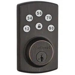
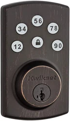
Touchpad Electronic Deadbolt
Installation & Learning Instructions
Owner’s Manual
Copyright © 2010 Kwikset Corporation
Part No: 40486 / 02

Table of Contents
Enclosed Pieces Page 1
1 Door Preparation Page 2
2 Deadbolt Latch Installation Page 2
3 Strike Installation Page 3
4 Touchpad Electronic Deadbolt Installation Page 4
5 Programming Instructions Page 6
6 Proper Operation of Touchpad Electronic Deadbolt Page 7
Notes and Warranty Page 8
Troubleshooting Tips Page 9

A
B
C
D
E
F
G
H
I
1
Pieces
Touchpad
Latch
Strike
Keys
Deadbolt
Mounting Plate
Power Strip
Power Board
Access Cover
Important Notes:
Use the components from this
package, make no substitutions.
Consult local building codes for
requirements in your area.
Read all instructions and lay out
parts as shown.
Under normal use it is recom-
mended to replace the batteries in
the Power Board once a year.
A
B
C
D E F
G
H
T-TURN
I
Enclosed Pieces
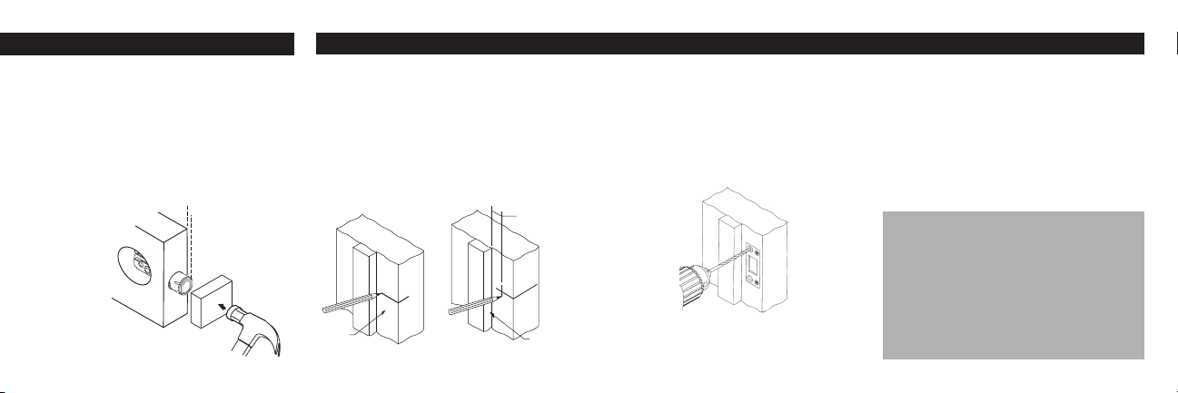
2. Deadbolt Latch Installation (Piece B)1. Door Preparation
Replacement Installation
Remove all old lock
components.
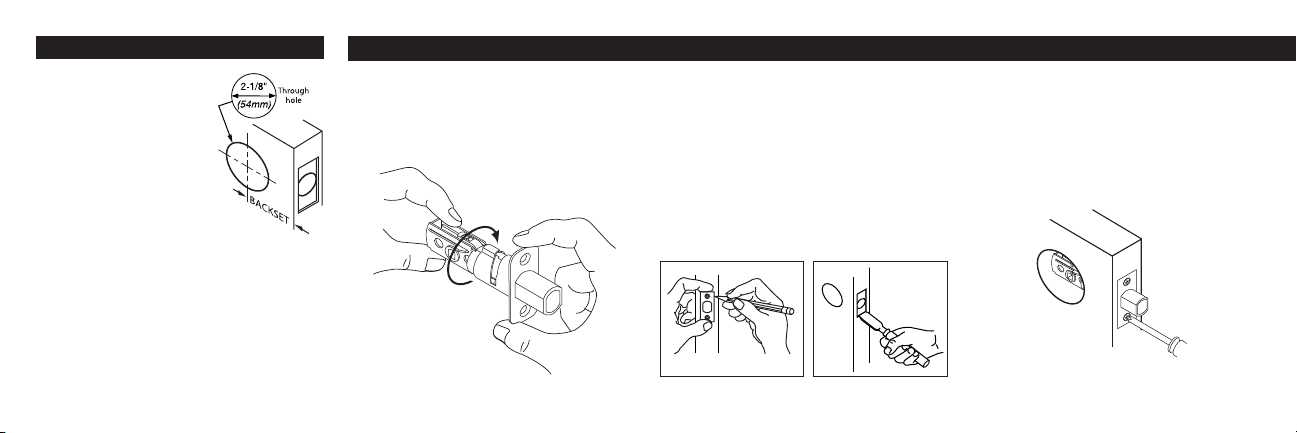
Use the enclosed template
to verify the following:
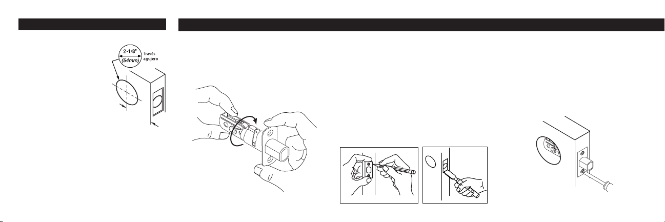
Deadbolt face hole needs to
be 2-1/8” (54mm) diameter.
Backset – Distance from
edge of door to center of
lock (2-3/8 or 2-3/4”).
Location to drill the small starter holes for
inside and outside trims.
Make any necessary modifications.
First-time Installation
Follow instructions on enclosed template.
Preparation for latch with Face Plate
Keeping edges parallel to the face of the door,
outline face plate and remove deadbolt latch
(see illustration below left).
Chisel outline of face plate until it is flush with
door edge, 5/32” (4mm) deep (see illustration
below right).
With bolt extended, insert deadbolt latch in
edge hole. Be sure to keep the word "UP" at
top. Secure with two 5/8” wood screws.
Install Latch
1
2
1
1
2
•
•
•
•
2
For latch with face plate:
To Adjust Backset:
Rotate to a 2-3/4” (70mm)
position, if required.
UP
2. Deadbolt Latch Installation (Piece B) 3. Strike Installation (Piece C)
With bolt retracted, insert deadbolt latch into
edge hole keeping flat edge of bolt parallel to
the edge of door. Be sure to keep the word
"UP" at top.
Using a wood block, tap with hammer until
surface of collar is flush with door edge
Re-extend bolt.
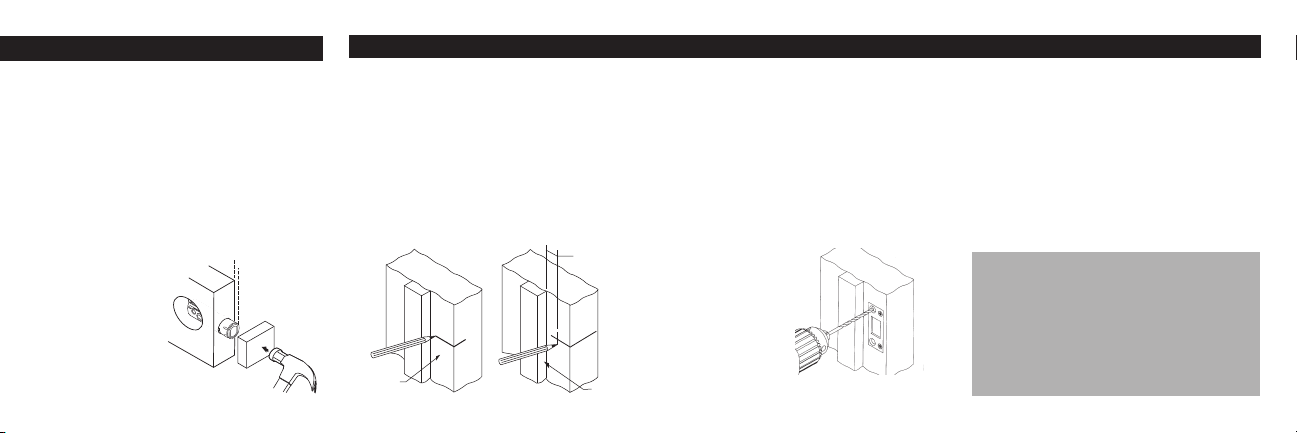
First-time Installation
Draw a horizontal centerline across the door
jamb, the same distance from floor as is the
centerline of deadbolt latch.
Measure back from door stop, 1/2 the
distance of the door thickness and draw a
vertical centerline. At crosspoint, drill a 1-1/8”
diameter (28.5mm) hole,1-1/4” (29mm) deep,
in the door jamb.
Center strike over hole and trace around
strike. Chisel out door frame until strike is
flush.
Position strike with large holes toward door
stop. Pre-drill large holes 3” (76mm) deep.
Important Note:
Deadbolt latch must enter strike
with no resistance or the Power-
bolt Touchpad Electronic Deadbolt
will not work properly.
1
2
1
2
3
U P
3
4
Door
Jamb
1/2 of door
thickness
Door
Stop
For Drive-In latch:
Install strike
Install 3” (76mm) screws in large strike holes
and install remaining 5/8” wood screws in
smaller holes.
Close door and ensure bolt extends and
retracts freely.
1
2
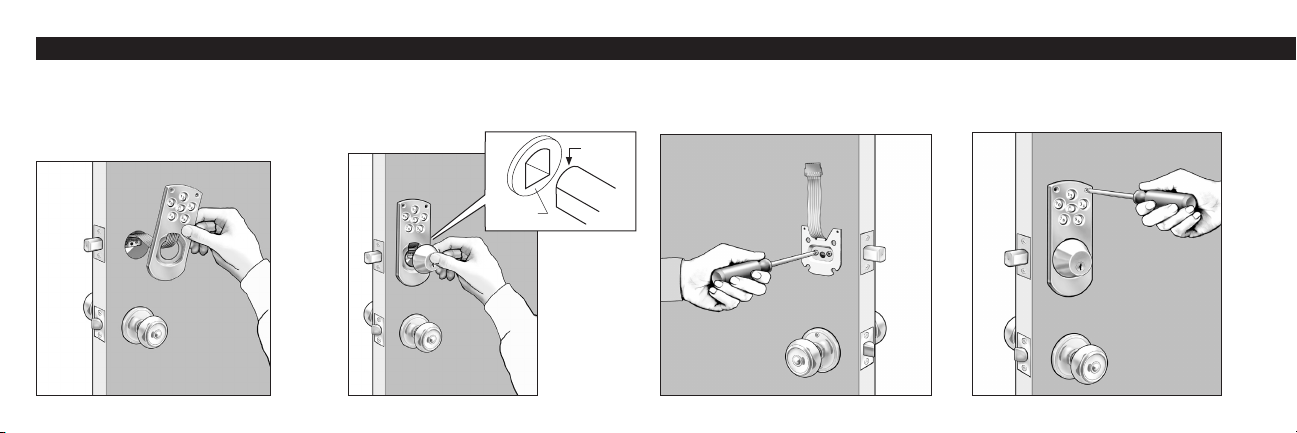
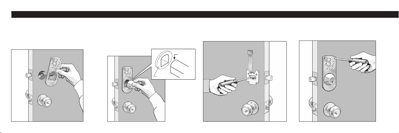
4. Touchpad Electronic Deadbolt Installation
With bolt of latch in the extended position,
place Touchpad A on outside of door and
place power strip G through door over top
of latch B. Note: Do not remove backing
from Touchpad.
With key removed, place deadbolt E against
Touchpad A with round of torque blade at top
to enter through crank of latch B.
Attach deadbolt with 2 large black bolts
through mounting plate F as shown. Power
strip G should extend out.
1 2 3
4
Line Touchpad A up with small holes from
template and attach with two 1” oval head
screws. Do not over-tighten screws.
4
Round
Crank
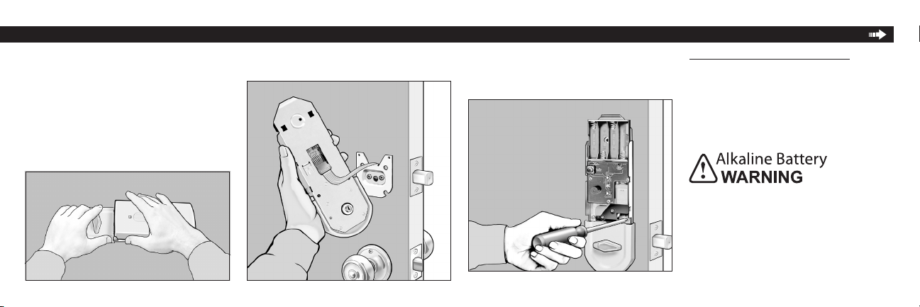
4. Touchpad Electronic Deadbolt Installation
Feed power strip G through large square hole
of Power Board H and plug into the 6 prongs.
Line Power Board H up to the 3 small holes
drilled from the template. Verify that torque
blade engages with the T-turn and attach
power board with 3 chrome-colored screws.
5
Remove access cover I from Power Board H.
Hold as shown in photo and twist or pull up
on cover.
5 6 7 Install 4 new AA Alkaline batteries (not
included in package). Battery positions shown
on battery case. A series of quick beeps will
sound when batteries make complete contact.
Low Battery Indicator Light on the Power
Board will be lit when the batteries need to be
replaced.
Do not dispose of in fire, recharge, put in
backwards, disassemble, mix with used or
other battery types. May explode or leak and
cause personal injury.
8
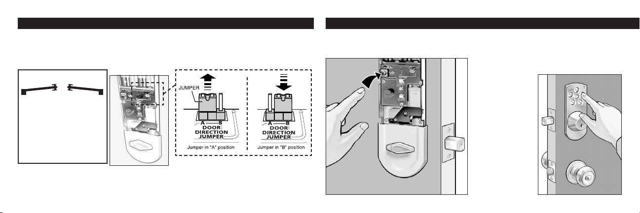
4. Touchpad Electronic Deadbolt Installation 5. Programming Instructions
Push program button on Power Board H once. 1
6
2
3
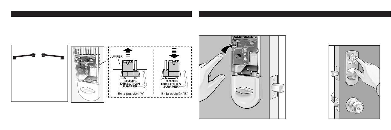
Retract deadbolt latch B with T-turn. Press the lock button on Touchpad A. If motor runs but
latch does not extend: Door handing needs to be changed. To change door handing, remove
jumper (located in the upper right corner of the circuit board) from position "A" and plug it into
position "B". See illustrations.
9
Verify key works in deadbolt E.
Note: When manually locking or unlocking the deadbolt by turning the key or the T-turn:
The motion will be rm — this resistance is normal.
Enter desired 4 to 8 digit code by pressing
numbers on outer Touchpad A. Press the
Lock button on Touchpad to set your code.
You will hear a 2-second long beep when your
code is accepted.
If unit does not
beep — too much
time has elapsed
between steps
1 and 2. Repeat
steps 1 and 2
faster.
10
From Exterior:
If hinge is on the left, you
have a left hand door.
If hinge on the right, you
have a right hand door.
Exterior
Right hand
Door
Left hand
Door
•
•
5. Programming Instructions 6. Proper Operation of Touchpad Electronic Deadbolt
7
To Enter Second Code
Push program button twice, then repeat steps
2-4.
5
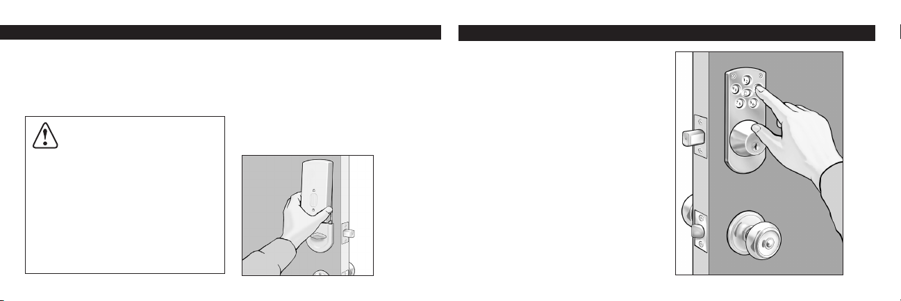
Push the Lock button on outside touch pad to
extend latch bolt 1” which locks the door when
you leave.
Enter your desired personal code to retract
the latch bolt completely which unlocks the
door when you return home.
The T-turn on the inside of the door is used to
extend (lock) or retract (unlock) the latch bolt
when you are inside.
Using the key from the outside will also extend
(lock) or retract (unlock) the latch bolt.
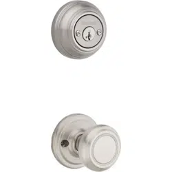
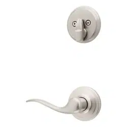
This Touchpad Electronic Deadbolt should be
accompanied by a Kwikset Knobset, Leverset,
or Handleset.
1
2
3
4
5
Enter your number to verify that it retracts
the latch B.
4 Snap access cover I onto power board H.
Align cover to top of power board and press
down at the bottom of the cover (see illustra-
tion below). To coordinate with your home
decorating scheme, the access cover may
be painted to
match your
door.
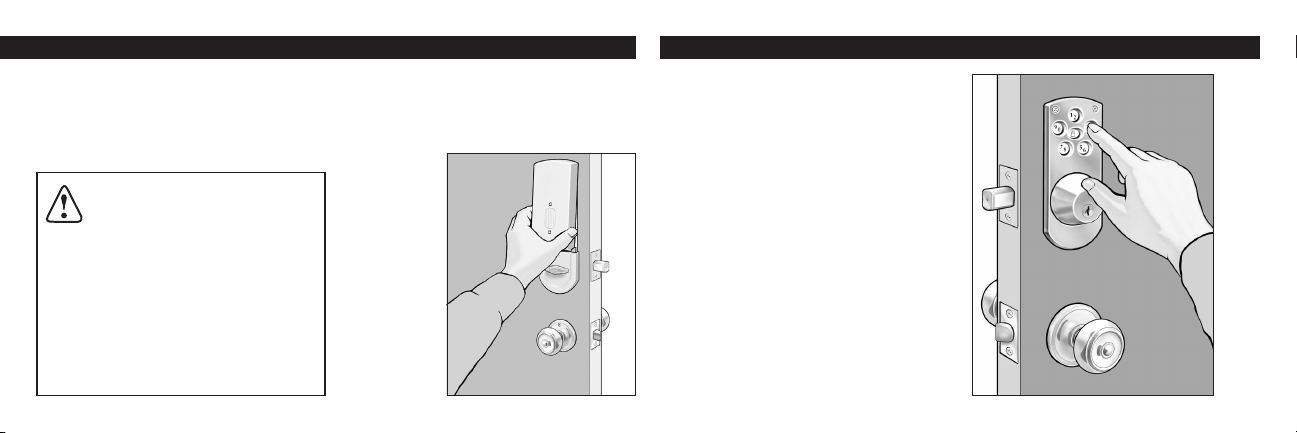
CAUTION: Prevent unauthorized
entry. This lock can be opened
using two different codes that are randomly
set at the factory. Upon installation and
set-up, replace both of these codes with
your own. Since anyone with access to the
power board can change these codes, you
must restrict access to the power board
and routinely check both codes to assure
they have not been altered without your
knowledge.

Important — Please Read Warranty Manufacture's note.
8
Under normal use it is recommended to
replace the batteries once a year. When
batteries are low, it will take longer to retract
the bolt. Batteries should be changed im-
mediately!
Lower latch must hold shut allowing deadbolt
latch to enter strike freely with no restrictions.
If door is misaligned, make necessary adjust-
ment to deadbolt strike location and/or hole
in door jamb to allow the deadbolt latch to
retract and extend freely.
Reprogramming of codes should not be
necessary after changing batteries.
If required, key can be used to retract
deadbolt.
If interior trim is exposed to extreme cold
temperatures, the batteries will not operate.
This is typical of all batteries and not a mal-
function of the lock.
•
•
•
WARNING: This Manufacturer
advises that no lock can provide complete
security by itself. This lock may be defeated
by forcible or technical means, or evaded
by entry elsewhere on the property. No lock
can substitute for caution, awareness of your
environment, and common sense. Builder’s
hardware is available in multiple performance
grades to suit the application. In order to
enhance security and reduce risk, you should
consult a qualified locksmith or other security
professional.
Full Lifetime Finish Warranty
Full Lifetime Mechanical Warranty
One Year Limited Electrical Warranty
This Warranty states all mechanical lock
parts will be free from defects in material and
workmanship, including deterioration over time
of finish on the exterior lock components while
the original purchaser owns the lock.
All electrical components are covered by a
One Year Limited Warranty.
Our warranty excludes locks that have been
damaged by installation contrary to our written
instructions or modified with non-Kwikset
components. It also excludes incidental
or consequential damages. (Some states
do not allow the exclusion or limitation of
incidental damages so this exclusion may
not apply to you.) To register a warranty
claim, please return the product, freight
prepaid to Attn: Consumer Services, Kwikset
Corporation, 19701 Da Vinci, Lake Forest,
California 92610. Kwikset will repair or replace
the lock or refund the purchase price (if it is
not practical to repair or replace). You will be
responsible for the removal of the old lock and
the installation of the new one.
This Warranty provides you with specific legal
right and you may also have other rights which
vary from state to state.

Troubleshooting Tips
9
If Electronics Are Not Working —
Check the Following:
Are your batteries good? Is the power strip
plugged in properly? (See step 4.6)
Are the batteries installed correctly and mak-
ing full contact? (See step 4.8) You should
hear a series of quick beeps when batteries
are installed correctly and making full contact.
Handing of Your Door
If the bolt does not extend when lock button is
pressed, check the handing of your door (See
Step 4.9)
Preset Factory Codes
This lock will maintain two different codes.
Two random codes are preset by the factory
for testing. It is recommended that you enter
Important Note:
Manual locking or unlocking the
deadbolt by turning the key or the T-
turn — the motion will be firm. This
resistance is normal for this lock.
two new security codes to cancel out the
preset codes. (See step 5).
Problems with Setting your Security Codes
— Check the Following:
You will hear a 2 second beep when your
codes are accepted. (See step 5.1-3).
If the unit does not beep — too much time has
elapsed between steps 1 & 2. Repeat these
steps faster.
Note: You have approximately 3 seconds
between step 1 & 2 for your codes to be
accepted. Please note the next statement.
Unauthorized Code Warning:
For your added security, a warning tone will
sound for 15 seconds if an incorrect security
code is entered three times consecutively. The
Touchpad will not operate for 1 minute.
Note: If several attempts were needed to
set your security codes — you may have
activated the warning sound. Wait 1 minute
for the unit to be operational again.
For assistance call
1-800-327-5625 USA
or visit www.kwikset.com


Cerrojo electrónico con teclado de contacto
Instalación e instrucciones de uso
Manual del propietario
Una compañía de Black & Decker
Impreso en E.U.A.
Copyright © 2010 Kwikset Corporation
Parte No: 40486 / 02
19701 DaVinci
Lake Forest, CA 92610
1-800-327-5625
www.kwikset.com

Table of Contents
Piezas incluidas Página 1
1 Preparación de la puerta Página 2
2 Instalación del pestillo Página 2
3 Instalación del recibidor Página 3
4 Instalación del cerrojo electrónico con teclado de contacto Página 4
5 Instrucciones de programación Página 6
6 Operación correcta del cerrojo electrónico con teclado de contacto Página 7
Notas y Garantía Página 8
Tips para solucionar problemas Página 9

Piezas incluidas
A
B
C
D
E
F
G
H
I
1
Pieces
Teclado de contacto
Pestillo
Recibidor
Llaves
Cerrojo electrónico
Placa de montaje
Cordel de energía
Panel de energía
Cubierta
Notas importantes:
Use los componentes de este
paquete; no haga sustituciones.
Consulte los códigos de con-
strucción locales para los
requerimientos especícos en su
zona.
Lea todas las instrucciones y
despliegue las partes como se
muestra aquí.
Bajo condiciones de uso nor-
males se recomienda reemplazar
las baterías del panel de energía
una vez al año.
A
B
C
D E F
G
H
Manija en T
I
Preparación para un pestillo con una
placa de cara.
1. Preparación de la puerta 2. Instalación del pestillo (Pieze B)
Para reemplazar una vieja cerradura:
Remueva todos los
componentes de la vieja
cerradura.
Use la plantilla aquí incluida
para verificar lo siguiente:
El agujero de empla-
zamiento del pestillo debe
medir 2-1/8" (54 mm) de
diámetro.
La distancia de la orilla de la
puerta a la bocallave debe medir
entre 2-3/8" o 2-3/4".
Ubicación de los pequeños agujeros guía
para las guarniciones interiores y exteriores.
Realice las modificaciones necesarias.
1
2
2
DISTANCIA
Para una instalación nueva:
Siga las instrucciones en la plantilla aquí
incluida.
Manteniendo los bordes paralelos al borde
de la puerta, trace el contorno de la placa y
remueva el pestillo (ver ilustración abajo a la
izquierda).
Con un formón, rebaje la superficie marcada
a una profundidad de 5/32" (4 mm) hasta
que quede al ras del canto de la puerta (ver
ilustración abajo a la derecha).
1
2
•
•
•
•
Con el perno extendió, inserte el pestillo en
el agujero. Cerciórese de que la palabra (UP)
está en la parte superior. Asegure la placa
con dos tornillos para madera de 5/8".
1
Instale el pestillo
Para un pestillo con una placa de cara:
Para ajustar la distancia del frente a la
bocallave:
UP
Gire a una posición de 2-3/4"
(70 mm), si es necesario.
2. Instalación del pestillo (Pieze B)
Instale el recibidor
3. Instalación del recibidor (Piece C)
Con el perno contraído, inserte el pestillo en
el agujero, conservando el canto plano del
pestillo paralelo a la superficie de la puerta.
Cerciórese de que la palabra (UP) está en
la parte superior.
Usando un pedazo de madera, pegue
ligeramente con un martillo hasta que la
superficie del collar quede al nivel del canto
de la puerta.
Instalación nueva
Marque una línea central horizontal a través
de la jamba de puerta, la misma distancia del
piso que es la línea central del pestillo.
Medida de la parada de la puerta,1/2 la dis-
tancia del grueso de la puerta y marque una
línea central vertical. Donde las líneas cruzan,
taladre un agujero de 1-1/8" (28,5 mm) de
diámetro y 1-1/4" (29 mm) de profundidad en
la jamba de la puerta.
Nota importante:
El pestillo debe entrar en el
recibidor sin resistencia, de
otro modo el cerrojo electrónico
Powerbolt no funcionará adecu-
adamente.
1
2
1
3
1
2
4
2
Para un pestillo con una cara redonda.
3
Centre el recibidor sobre el agujero y
marque una línea a su alrededor. Rebaje
la jamba de la puerta con un formón hasta
que el recibidor quede al ras de la superficie
de ésta.
Coloque el recibibor con los agujeros más
grandes hacia el tope vertical de la puerta.
Taladre los agujeros grandes a 3" (76 mm)
de profundidad.
Jamba
de puerta
1/2 de grueso
de la puerta.
La Parada de puerta.
Coloque los tornillos de 3" (76 mm) en los
agujeros grandes del recibidor y los tornillos
de madero remanentes (de 5/8") en los aguje-
ros pequeños.
Cierre la puerta y verifique que el pestillo se
extiende y se retrae libremente.
Extienda el pestillo
de nuevo.
U P
Amplíe el perno del pestillo. Coloque el
teclado de contacto A por fuera de la puerta
y pase el cordel de energía G por la puerta
por encima del pestillo B. Nota: No quite la
cubierta al reverso del teclado de contacto.
Sacándole la llave, ensamble el cerrojo
electrónico E en el teclado de contacto A.
Cerciórese de que la porción redonda de la
lámina de torsión esté en la parte supe-
rior para entrar a través de la manivela del
pestillo B.
Asegure el cerrojo con los dos tornillos negros
grandes, por el lado de la placa de montaje F,
como aparece en la ilustración. El cordel de
energía G debe quedar saliendo.
1 2 3
4
Centre el teclado de contacto A sobre los
agujeros pequeños de la plantilla y asegúrelo
con dos tornillos cabeza ovalada de 1"
(2.54 cm). No apriete demasiado los tornillos.
4
4. Instalación del cerrojo electrónico con teclado de contacto
Redondo
Manivela

4. Instalación del cerrojo electrónico con teclado de contacto
Pase el cordel de energía G por el agujero
cuadrado grande del panel de energía H y
enchúfelo en las 6 agujillas terminales.
Centre el panel de energía H sobre los tres
pequeños agujeros que hizo con la plantilla.
Verifique que la lámina de torsión enganche
con la manija en T y asegure el panel de
energía con tres tornillos cromados.
5
Retire la cubierta I del panel de energía H.
Sosténgalos de la manera que aparece en la
ilustración y gire o jale la cubierta hacia arriba.
5 6 7 Instale 4 baterías alcalinas AA nuevas
(no incluidas en el paquete). La posición de
las baterías se muestra en la caja de éstas.
Una serie de rápidos tonos bip se escuchará
cuando las baterías hagan contacto completo.
La luz indicadora de las baterías en el panel
de energía se encenderá cuando las baterías
necesiten cambiarse.
No disponga en fuego, recargue, ponga ad-
entro al revés, desmonte, mezcle con usada
u otros tipos de la batería. Una batería podría
escaparse o estallar y podría causar lesión
corporal.
8
5. Instrucciones de programación
Oprima una vez la tecla “Program” del panel
de energía H.
1
6
Retraiga el pestillo B utilizando la manija. Oprima la tecla Cerrar [lock] en el teclado de contacto
A. Si el motor gira pero el pestillo no sale, La mano de la puerta, necesidades de ser cambiado.
Para cambiar la mano de la puerta: Quite el interruptor "jumper" (localizado en la esquina
derecha superior del tablero de cicuito) del position "A" y coloqúelo en la posición"B". Vea las
ilustraciones.
9
Verifique que las llaves abren y cierran el cerrojo electrónico E.
Nota: Al abrir o cerrar manualmente el cerrojo electrónico con la llave o la manija, el
deslizamiento del pestillo será rme, con cierta resistencia normal.
Ingrese su código personal (4 a 8 dígitos)
oprimiendo los números en el teclado de con-
tacto A exterior. Oprima la tecla Cerrar [lock]
para fijar el código deseado.
Al quedar
aceptado su
código, escuchará
un tono bip de 2
segundos.
Si la unidad no
emite el tono, es
señal de que ha
transcurrido de-
masiado tiempo
entre los pasos
1 y 2. Repítalos
rápidamente.
10
2
3
Exterior
Lado
derecho
Lado
izqulerdo
De Exterior:
Si la bisagra està en el lado
izquierdo de la puerta, la puerta es
de mano izquierda.
Si la bisagra està en el lado
derecho de la puerta, la puerta es
de mano derecho.
•
•
4. Instalación del cerrojo electrónico con teclado de contacto (continuado)
5. Instrucciones de programación 6. Operación correcta del cerrojo electrónico con teclado de contacto
7
Para ingresar un segundo código
Oprima dos veces la tecla “Program” y
repita los pasos 2-4.
5
Oprima la tecla Cerrar [lock] en el panel de
contacto exterior para extender el pestillo 1"
(2,54 cm) y cerrar la puerta cuando usted
sale.
Ingrese su código confidencial para retraer
completamente el pestillo para abrir la puerta
cuando usted regresa a casa.
La manija en T, en el interior de la puerta, se
utiliza para extender (cerrar) o retraer (abrir)
el pestillo desde adentro.
El pestillo también se extiende (cierra) o
retrae (abre) usando la llave por fuera.
Este cerrojo electrónico con teclado de
contacto debe usarse junto con una cerradura
Kwikset de tipo perilla, manija o manilla.
Ingrese su número confidencial para
verificar que el pestillo (B) se retrae.
4 Acomode la cubierta I sobre el panel de
energía H. Ponga la cubierta en línea con la
parte superior del panel de energía y presione
la parte inferior de la cubierta (ver ilustración
abajo). Puede pintar la cubierta a tono con la
puerta, para coordinarla con su decorado.
PRECAUCIÓN: Evite que se
entre sin autorización. Esta cerra-
dura puede abrirse utilizando dos
códigos distintos que se configuran al azar
en la fábrica. Cuando lo instale y lo con-
figure, reemplace esos dos códigos con
los suyos. Como cualquiera que tenga
acceso al tablero de distribución puede
cambiar esos códigos, tiene que restringir
el acceso al tablero de distribución y veri-
ficar los dos códigos con regularidad para
asegurarse de que no se han alterado sin
que usted lo sepa.
1
2
3
4
5

Importante — Favor de leer Nota del fabricanteGarantía
8
Bajo uso normal se recomienda cambiar las
baterías una vez al año. Entre más gastadas las
baterías, más tiempo tardará en abrirse el cer-
rojo. De ser así, ¡las baterías deben cambiarse
inmediatamente!
Verifique que la puerta esté bien alineada e ingrese
el código de nuevo.
El pestillo inferior debe asentarse firmemente para
que el pestillo del cerrojo electrónico pueda entrar
sin ningún obstáculo.
Si la puerta no está bien alineada, haga los ajustes
necesarios al emplazamiento del cerradero y/o en
la jamba de la puerta para permitir que el pestillo
pueda entrar y salir libremente.
No debe ser necesario reprogramar los códigos
después de cambiar las baterías.
De ser necesario, se puede usar la llave para abrir
el cerrojo.
Si se expone la guarnición interior a temperaturas
extremadamente bajas, las baterías no funciona-
rán, lo cual es típico de toda batería y no significa
malfuncionamiento de la cerradura.
•
•
•
ADVERTENCIA: Este Fabricante
hace saber que no hay cerrojos que puedan
proporcionar completa seguridad por sí
mismos. Puede hacerse que falle este cerrojo
forzándolo o utilizando medios técnicos, o
puede evadirse entrando por otra parte de
la propiedad. No hay cerrojos que puedan
hacer de sustitutos para la precaución, el
estar al tanto del entorno, y el sentido común.
Pueden obtenerse piezas de ferretería de
constructor con diversos grados de ren-
dimiento para ajustarse a la aplicación. Para
realzar la seguridad y reducir los riesgos,
debe consultar con un cerrajero capacitado u
otro profesional de seguridad
Garantía completa de por vida sobre el acabado
Garantía completa de por vida sobre
componentes mecánicos.
Garantía limitada de un año sobre componentes
eléctricos
Esta garantía establece que todos los componentes
mecánicos estarán libres de defectos de materiales y
de mano de obra, incluyendo deterioro con el tiempo,
del acabado de los componentes exteriores de la
cerradura mientras que el comprado original sea
dueño de ésta.
Todos los componentes eléctricos llevan una garantía
limitada de un año.
Nuestra garantía excluye cerradura que hayan
sido dañadas por instalación contraria a nuestas
instrucciones escritas, o que hayan sido modificadas
con productos no provenientes de Kwikset. La
garantía tampoco incluye daños incidentales o
consecuenciales. (Algunos estados no permiten
la exclusión o limitación de daños incidentales,
por lo que esta exclusión puede no ser válida
para usted.) Para presentar reclamos de garantía,
por favor regrese el producto, con flete prepagado a:
Atención: Consumer Services, Kwikset Corporation,
19701 Da Vinci, Lake Forest, California 92610.
Kwikset reparará o reemplazará la cerradura o
reembolsará el precio del producto (si no es práctico
reparar o reemplazar). Será responsabilidad de usted,
desarmar el producto viejo e instalar el nuevo. Esta
garantía la proporciona derechos legales especificos,
además de los que pueden beneficiarle y que varían
con cada estado.

Impo rtado r:
Blac k & D ecker S.A. d e C.V.
Bosq ues d e Cidr os Acce so Rad iatas #42
Col. Bosq ues de Las L omas
CP 0 5120 M exico , D.F.
Tel.: 5 5-532 6-7100
Tip para solucionar problemas
9
Si no funcionan las partes electrónicas,
revise lo siguiente:
¿Están buenas sus baterías? ¿Está debida-
mente enchufado el cordel de energía? (Ver el
paso 4.6).
¿Están correctamente instaladas y haciendo
contacto las baterías? (Ver el paso 4.8). Cuan-
do las baterías se han instalado correctamente
y están haciendo contacto, usted escuchará
una rápida serie de tonos bip.
La orientación de su puerta
Si el pestillo no se extiende al oprimir el botón
Cerrar [lock], verifique si su puerta es de mano
derecha o izquierda (ver el paso 4.9).
Códigos jados de fábrica
Esta cerradura puede guardar dos códigos.
Viene con dos códigos de prueba instalados
de fábrica. Se recomienda que usted ingrese
Nota importante:
Al abrir o cerrar manual-mente
el cerrojo electrónico usando
la llave o la manija en T, el
deslizamiento del pestillo será
rme. Cierta resistencia es nor-
mal en esta cerradura.
sus dos nuevos códigos de seguridad para
cancelar los originales. (Ver el paso 5).
Problemas al jar los códigos de seguri-
dad – Revise lo siguiente:
Al quedar aceptados su códigos, escuchará
un tono bip de 2 segundos. (Ver el paso 5,
1-3).
Si la unidad no emite el tono bip, ha transcur-
rido demasiado tiempo entre los pasos 1 y 2.
Repita estos pasos en un tiempo menor.
Nota: Entre los pasos 1 y 2, usted dispone
aproximadamente de 3 segundos para que
queden aceptados sus códigos. Lea por
favor lo siguiente:
Alarma de código no registrado:
Para su seguridad adicional, sonará un tono
de aviso durante 15 segundos cuando se
ingrese tres veces consecutivas un código de
seguridad incorrecto. El teclado de contacto
dejará de operar durante 1 minuto.
Nota: Si se requirieron varios intentos para
jar su código de seguridad, es posible
que usted haya activado el tono de alarma.
Espere 1 minuto para que la unidad opere
de nuevo.
Si desea ayuda llame al
1-800-327-5625 USA
o visite www.kwikset.com