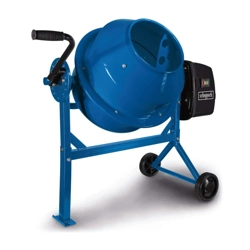
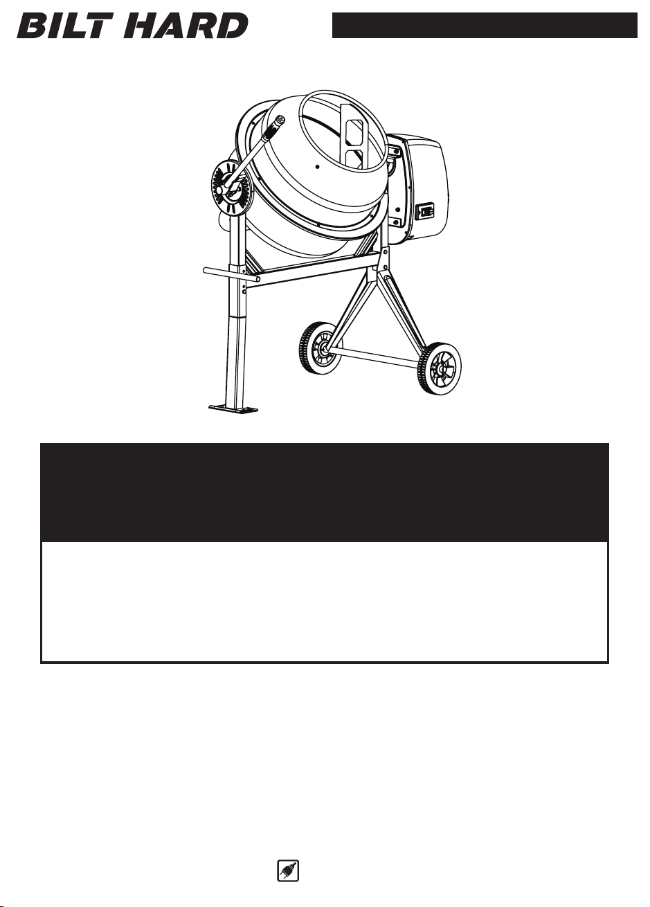
Concrete Mixer
Owner’s Manual
SKU : TL-CM115
Both model number and serial number may be found on the main label.
You should record both of them in a safe place for future use.
FOR YOUR SAFETY
READ AND UNDERSTAND THE ENTIRE MANUAL BEFORE OPERATING
MACHINE
Save This Manual for Future Reference
110 ~ 127V
Customer Support:(888) 680-2849, [email protected]

SAFETY WARNINGS & INSTRUCTIONS
SYMBOL AFFIXED TO THE MACHINE
3
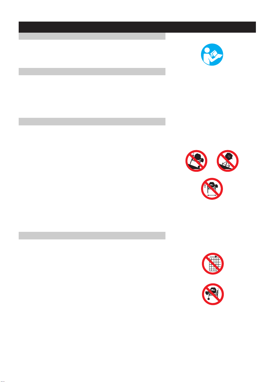
l UNDERSTAND YOUR MIXER
Read and understand the owner’s manual and labels affixed
to the mixer. Learn its application and limitations as well as
the specific potential hazards peculiar to it.
Become familiar with the controls before operating this mixer.
l STAY ALERT
Do not operate the mixer while under the influence of drugs,
alcohol, or any medication that could affect your ability to use
it properly.
Do not use this mixer when you are tired or distracted from
the job at hand. Watch what you are doing at all times. Use
common sense.
l AVOID DANGEROUS CONDITIONS
Make sure there is adequate surrounding workspace.
Keep your work area clean and well lighted. Cluttered areas
invite injuries. Keep area around the mixer clear of obstructions,
grease, oil, trash and other debris which could cause persons
fall onto moving parts.
Only use or operate the mixer on solid, flat, level ground that
is capable to support the weight of the mixer and its load to
prevent the mixer from tipping over.
Do not attempt to move the mixer when it is loaded and/or
in operation.
This mixer is intended for the production of concrete, mortar
and plaster. It is not suitable for the mixing of flammable or
explosive substances. Do not use it in areas where fumes
from paint, solvents or flammable liquids pose a potential
hazard.
l INSPECT YOUR MIXER
Check your mixer before turning it on. Keep guards in place
and in working order. Do not plug mixer with motor cover off.
Check all bolts, nuts, and screws for tightness before each
use, especially those securing guards and drive mechanisms.
Vibration during mixing may cause these to loosen.
Form a habit of checking to see that all the adjusting tools,
shovels, hand trowels and other tools/equipments are removed
from mixer area before turning it on.
Replace damaged, missing or failed parts before using it.
Warning labels carry important information. Replace any
missing or damaged warning labels.

SAFETY WARNINGS & INSTRUCTIONS
SYMBOL AFFIXED TO THE MACHINE
4
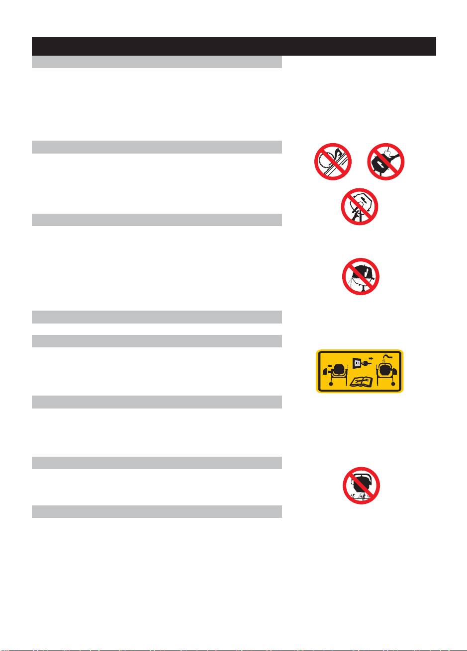
l DRESS PROPERLY
Do not wear loose clothing, gloves, neckties or jewelry (rings,
wrist watches). They can be caught in moving parts. Protective
electrically non-conductive gloves and non-skid footwear are
recommended when working. Wear protective hair covering
to contain long hair, preventing it from getting caught in
machinery. Wear a face or dust mask if the operation is dusty.
Always wear safety goggles and/or face shields. Everyday
eyeglasses have only impact resistant lenses. They are not
safety glasses.
l DO NOT ABUSE CORD
Never carry mixer by cord or yank it to disconnect it from
socket.
Keep cord from heat, oil and sharp edges.
l EXTENSION CORDS
Extension cords must be no longer than 50 meters in length.
The wire section must be 1.5mm on 120V to allow sufficient
2
current flow to the motor. Improper use of extension cords
may cause inefficient operation of the mixer which can result
in overheating and motor damage.
Only extension cords to H07RN-F specification intended for
outdoor purpose may be used. Avoid use of free and
inadequately insulated connections. Connections must be
made with protected material suitable for outdoor use. Make
sure that any extension cord connections are dry and safe.
Ensure that the extension cord is carefully laid out avoiding
liquids, sharp edges and places where vehicles might run over
it. Avoid allowing the extension cord to be trapped underneath
the mixer. Unroll it fully or it will overheat and could catch fire.
l AVOID ELECTRICAL SHOCK
Check that the electric circuit is adequately protected and that
it corresponds with the power, voltage and frequency of the
motor.
Do not plug or unplug the motor while standing in or around
damp or wet ground. Do not use the mixer in wet or damp
areas or expose it to rain.
Prevent body contact with grounded surfaces: pipes, radiators,
ranges, and refrigerator enclosures.
Make sure your fingers do not touch the plug’s metal prongs
when plugging or unplugging the mixer.
l KEEP VISITORS AND CHILDREN AWAY
Keep unauthorized persons away from the mixer.
Do not allow children to handle or climb on or in the mixer.
SAFETY WARNINGS & INSTRUCTIONS
SYMBOL AFFIXED TO THE MACHINE
5
DO NOT OVERREACH
Keep proper footing and balance at all times when loading
or unloading the mixer.
Never stand on mixer. Serious injury could occur if the mixer
is tipped or if the moving parts are unintentionally contacted.
Do not store anything above or near the mixer where anyone
might stand on the mixer to reach them.
AVOID INJURY FROM UNEXPECTED ACCIDENT
Keep hands out of the way of all moving parts. Do not place
any part of your body or any tool, like shovel in the drum
during operation. When operating, do not pass hands through
the clearance between frame and support arm or the one
between the drum and support arm.
DO NOT FORCE TOOL
It will do a better and safer job at its design rate. Always work
within the rated capacity.
Do not start the motor if the drum is fully loaded. Do not turn
mixer off while full of concrete.
Do not use the mixer for a purpose for which it was not
intended.
The mixer is not to be towed by any vehicle.
NEVER LEAVE MIXER RUNNING UNATTENDED
Do not leave mixer until it has come to a complete stop.
DISCONNECT POWER
Never open the motor cover before unplugging the mixer.
Disconnect from power supply when not in use, before moving,
making adjustments, changing parts, cleaning, or working on
the mixer. Consult technical manual before servicing.
MAINTAIN YOUR MIXER WITH CARE
Clean the mixer immediately after use. Keep the mixer clean
for best and safest performance.
When maintaining this mixer, only
the manufacturer’s original
replacement parts may be used.
PROTECT THE ENVIRONMENT
Take left over materials to an authorized collection point or
follow the stipulations in the country where the mixer is used.
Do not discharge into drains, soil or water.
STORE IDLE EQUIPMENT
When not in use, the mixer should be stored in a dry location
to inhibit rust. Keep the mixer away from children and others
not qualified to use it.

Safety Warnings & Instructions ………………...…………………………………………….….......... 3
Specifications……………………………………………………………………………........................ 6
Contents of Shipping Container ………………………………………………………………….......... 7
Assembly Instructions ………………...…………………………………………………………........... 8
Operation Instructions …………………………………………….……………………………........... 12
Maintenance Instructions ………………………………………………………………………............13
Wiring Diagram ………………..…………………………………………………………………...........13
Parts Schematic ……………………………………………………………………………….............. 14
Parts Schematic ……………………………………………………………………………….............. 15
TABLE OF CONTENTS
6
SPECIFICATIONS
SKU
Motor
Drum Speed
Drum Capacity
Drum Opening
Overall Sizes
L
W
H
Weight
TL-CM115
Model Number
HCM400
120V-60Hz 5A
26.7rpm
4 Cubic Feet
385 mm
1200 mm
710 mm
1350 mm
41 kg
7
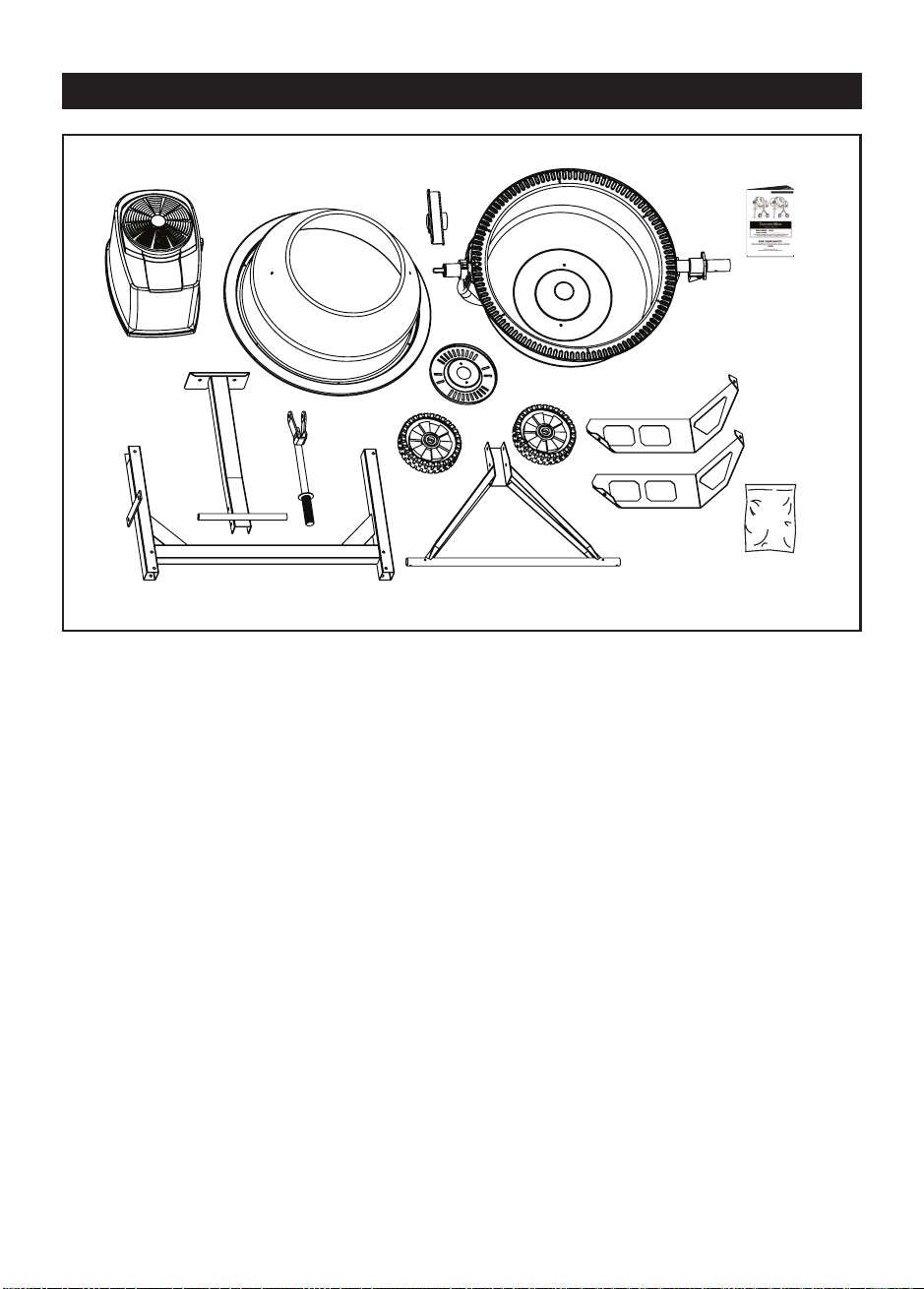
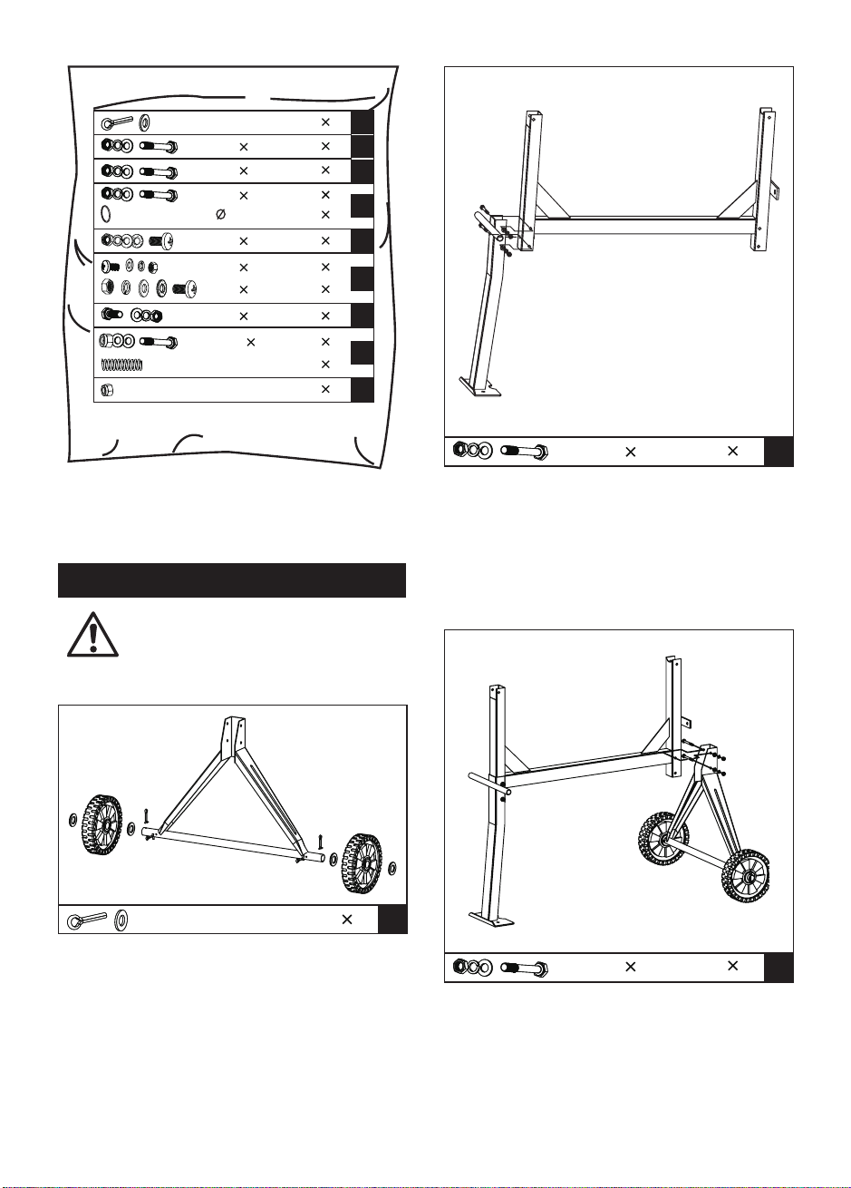
CONTENTS OF THE SHIPPING CONTAINER
8
Two people assist in assembly
recommended.
ASSEMBLY INSTRUCTIONS
THE STAND
With a split pin inserted into the inner holes
in each stub axle, place a flat washer, then
a wheel followed by another flat washer.
Insert another split pin into the axle holes
outside each flat washer. Bend each side of
the pins outward so they do not fall out.
1.
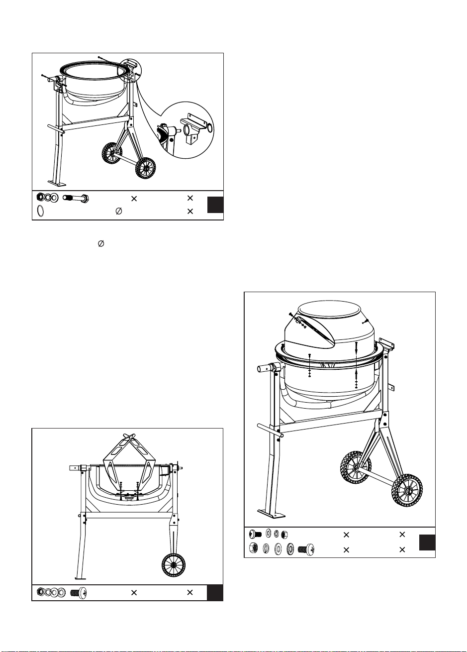
Turn the frame over and attach the axle
bracket with wheels in the same manner.
3.
Make sure all bolts and nuts are tightened.4.
With the frame lying on its side, attach the
support leg as shown. Insert two M8X70 hex
bolts through the holes from one side, then
flat washers, lock washers and nuts from the
other side.
2.
C
2
M8 70
B
2
M8 70
A
4
A
B
C
D
E
F
G
H
I
2
6
2
1
1
2
4
2
2
2
4
M8 70
M8 70
M8 65
M8 20
M8 20
M8 20
M8 25
M10 65
M8
142
9
THE MIXING BLADES
NOTE:
THE BOTTOM DRUM
THE UPPER DRUM
Mount the mixing blades inside the bottom drum
loosely as shown - Two holes are provided at
the base of the drum into which a M8X20 bolt
may be inserted from the outside. A leather
washer, flat washer, lock washer and a nut
should be threaded on loosely on the inside.
The leather washer should be placed under the
blade down against the drum.
Two arrows are labeled on upper
drum and bottom drum to make
their position relation. If you have
any difficulty in correctly
positioning the mixing blades, it is
helpful if you temporarily mount
the upper drum on the top of the
bottom drum, rotating it so that the
two arrows line up.
Position the upper drum on bottom drum
over the rim, making sure the mounting holes
align in both as well as the labeled arrows.
1.
Carefully, and with two people, set the bottom
drum with support arm onto the side supports
of the stand as shown, so that the bearing
blocks slot into the channels provided by the
side supports. The larger diameter shaft
should be at the leg end of the stand.
2.
At each side, line up the holes in the side
support with those in the bearing block and
insert a M8X65 hex bolt from one side, then
a flat washer, lock washer and nut from the
other side. Tighten with a wrench.
3.
F
6
2
M8 20
M8 20
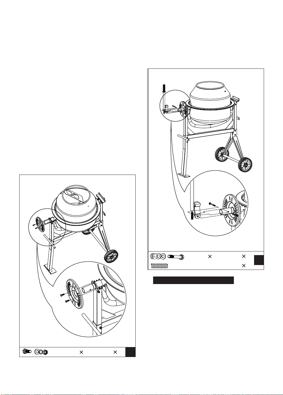
Slide the bearing block on the shaft. Hold it
in place with 42 spiral ring.
1.
E
2
M8 20
D
2
M8 65
142
10
THE TIPPING BAR
2.
Insert a M8X20 cross headed screw into each
mounting holes in the rim. Secure each bolt
from below with a flat washer, lock washer
and nut. Make sure the tightening process
is carried out progressively.
Secure the mixing blades to the upper drum
by inserting two M8X20 cross headed screws,
from the outside through the holes in the
drum.
3.
A leather washer should be positioned inside
between the drum and blade. Secure the
mixing blade on the inside using a flat washer,
spring washer and nut.
4.
Slide the locking plate over the large diameter
shaft at the leg end of the frame with the rim
facing inwards as shown. Secure with
two
M8X25 bolts, each with a nut, lock and flat
washers.
1.
Finally, ensure top and bottom mixing blade
mountings are tight.
5.
G
2
M8 25
H
1
1
M10 65
For Tipping Bar Model Only - Insert the
spring into the bar pipe. Holding it in place
with a finger, place the bar over the larger
diameter shaft so that the shaft retains the
spring. Press down on bar until the holes in
the bracket line up with the hole drilled. Insert
a M10X65 hex bolt and screw on a nut with
flat washers from the other side. Screw the
nut up against the bracket firmly, but not so
tightly so as to prevent the bar from pivoting
about the bolt.
2.
11
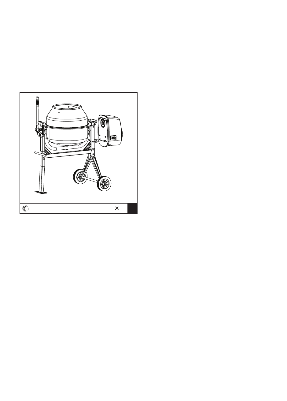
THE TRANSMISSION CASE
Lining up the keyways, slide the transmission
case over the pinion shaft. Secure the case to
the frame with four M8 lock nuts.
NOTE:
I
4
M8
The bar must be allowed to pivot
about the bolt so that the lugs on
the bracket can be engaged or
disengaged from the slots in the
locking plate.
12
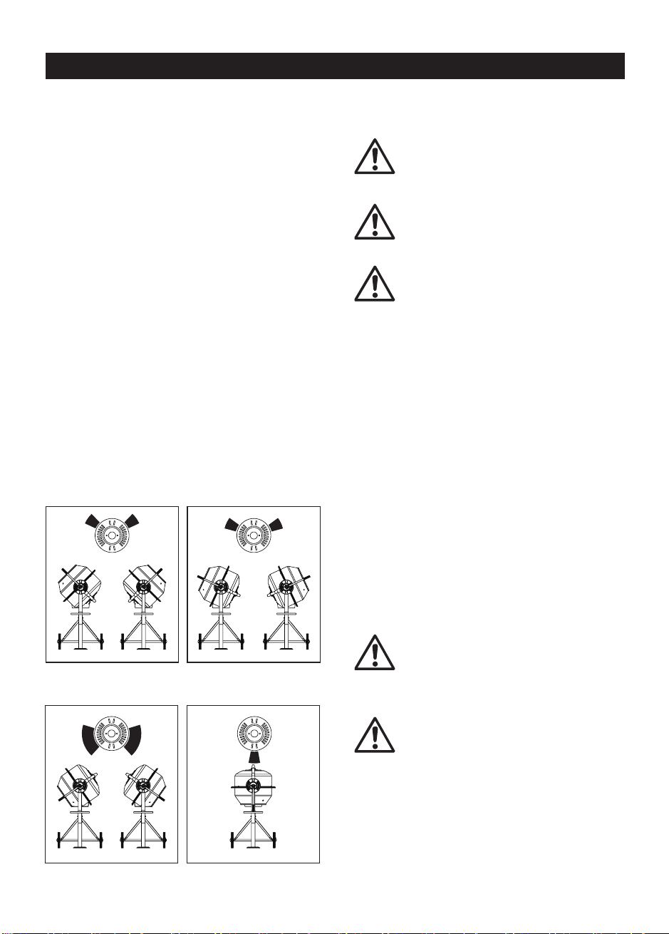
OPERATION INSTRUCTIONS
DRUM TILTING
The spring-loaded tipping bar with locking lugs
provides an easy positive control of the drum
which can be locked in the mix, discharge and
stored position.
The drum is locked in position by lugs on the
self-locating tipping bar which engage into the
locking plate on the mixer frame. To tilt the
drum, withdrawn the tipping bar to dis-engage
the locking lugs. This then allows the tipping
bar and drum to be turned in the same
direction.
To retain the drum in position, aligning the lugs
with the slots, release the tipping bar a little
while retaining the drum. Rotate the tipping
Loading/Mixing Position
For Mortar For Concrete
Emptying Position Storage Position
LOADING
Completely unwind the extension
cord. Connect it to the concrete
mixer first before plugging in power
supply.
Always start the mixer before
loading the drum. Loading the drum
with drum rotating.
Do not throw material into the mixer
to avoid sticking firmly to the back
of the drum. Trickle it steadily over
the ram.
For best results, proceed as follows:
1. Add the required amount of gravel into the
drum.
Add the required amount of cement into the
drum.
2.
Add the required amount of sand into the
drum.
3.
Pour the required amount of water into the
drum.
4.
A bu
ilt-in thermal protecter is
arranged in the motor to prevent it
from overheating. The thermal
protecter restores automatically
when the motor cools down.
NOTE:
EMPTYING
CLEANING
Do not turn mixer off while full of
load. Emptying the drum with drum
rotating.
Never put hands inside the drum
with drum rotating.
bar until the locking lugs engage into the
locking plate on the mixer frame.
13
Thoroughly clean the mixer at the end of each
day’s operation. Keep your mixer clean. The
slightest trace of material left in the drum will
harden and attract more each time you use it
until the machine is useless. Dried cement
should be scraped out of the drum. Do not throw
bricks into mixer drum to clean it out. Do not
beat on the drum with a shovel, a hammer or
other tools to break up accumulations of dried
cement mix, as damage to the mixer may result.
The drum may be scoured for approximate 2
minutes, using 1” gravel and water mixture.
Then discharge the gravel/water mixture and
hose down the drum assembly inside and out.
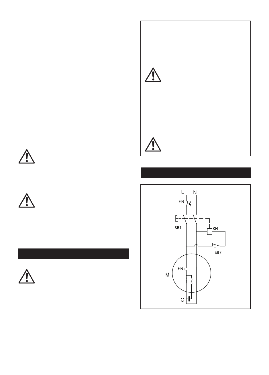
WIRING DIAGRAM
Do not pour or spray water directly
over the motor cover, especially
the openings in it.
Wipe off any external material on
the motor cover. Do not use petrol,
turpentine, lacquer or paint thinner,
dry cleaning fluids or similar
products. The use of chemical
products or solvents may affect
the properties of the cover which
was made of high densit y
polyethyiene PET.
Ensure the extension cord is
always unplugged before the motor
cover is removed.
MAINTENANCE INSTRUCTIONS
The drive belt is under constant even tension
by a spring loaded jockey. No adjustment apart
from a touch of grease on the spindle.
The bearings are sealed for life.
The wiring diagram and parts
schematic in this manual are as
reference tools only. Neither the
manufacturer nor distributor
makes any representation or
warranty of any kind to the buyer
that he or she is qualified to
make any repairs to the product
or that he or she is qualified to
replace any parts of the product.
Only qualified technicians
should repair the mixer. Any
maintenance and repairs carried
out, to any of the electric
components must be undertaken
by a qualified electrician.
Parts in a circle should
only be
fitted by a qualified electrician.
The IP44D protection class construction of the
concrete mixer enables you to hose down the
drum assembly safely.
14
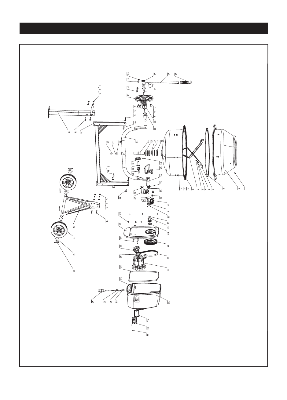
PARTS SCHEMATIC

15
PARTS LIST
No.
1
2
3
4
5
6
7
8
9
10
11
12
13
14
15
16
17
18
19
20
21
22
23
26
27
28
29
30
31
32
33
34
35
36
37
38
39
40
Description
Cross Headed Screw M8X20
Waterproof Washer
Flat Washer 8
Spring Washer 8
Nut M8
Upper Drum
Mixing Blade
Rubber Gasket
Lower Drum
Axle Bracket
Wheel
Flat Washer 27
Cotter Pin 5X40
Frame
Support Leg
Bolt M8X70
Bearing Block - Right
Circlip 42
O-ring
Gear Guard - Long
Drive Shaft
Sleeve Pipe
Cradle
Bearing 6206
Circlip 62
Circlip 30
Lock Pin 5X40
Self Tapping Screw ST4.2X13
Drive Pinion
Gear Guard - Short
Circlip 42
Bearing 6202
Circlip 15
Lock Nut M8
Bolt M8X65
Circlip 38
Bearing Block - Left
Lock Nut M10
Q'ty
10
4
22
18
18
1
2
1
1
1
2
4
4
1
1
4
1
1
1
1
1
2
1
2
3
1
1
3
1
1
1
2
1
4
2
2
1
1
No.
41
42
43
44
45
46
47
48
49
50
51
52
53
54
55
56
57
58
59
60
61
62
63
64
65
66
67
68
69
70
71
72
73
Description
Flat Washer 10
Tipping Wheel
Spring
Hex.head bolt M10X65
Tipping Bar
Handle Grip
Bolt M8X25
Locking Plate
Power Cord
Strain Relief Nut
Strain Relief Rubber
Strain Relief Bolt
Strain Relief Nut
Gasket, Switch
Switch
Motor Cover
Motor
Idle Pulley
Belt
Bearing 6906
Snap Washer – Hole 47
Self Tapping Screw ST4.2X16
Circlip 30
End Plate
Bolt M8X25
Motor Mount Bracket, End Plate
Gasket
Self Tapping Screw ST3.5X16
Oil seal 62x35x8
Fixed Shaft
Washer
Spring Washer 12
Bolt M12x35
Q'ty
2
1
1
1
1
1
5
1
1
1
1
1
1
1
1
1
1
1
1
2
1
6
1
1
3
1
1
2
1
1
1
1
1

PLEASE READ THE FOLLOWING CAREFULLY
THE MANUFACTURER AND/OR DISTRIBUTOR HAS PROVIDED THE PARTS LIST AND ASSEMBLY DIAGRAM
IN THIS DOCUMENT AS A REFERENCE TOOL ONLY. NEITHER THE MANUFACTURER OR DISTRIBUTOR
MAKES ANY REPRESENTATION OR WARRANTY OF ANY KIND TO THE BUYER THAT HE OR SHE IS
QUALIFIED TO MAKE ANY REPAIRS TO THE PRODUCT, OR THAT HE OR SHE IS QUALIFIED TO REPLACE
ANY PARTS OF THE PRODUCT. IN FACT, THE MANUFACTURER AND/OR DISTRIBUTOR EXPRESSLY
STATES THAT ALL REPAIRS AND PARTS REPLACEMENTS SHOULD BE UNDERTAKEN BY CERTIFIED AND
LICENSED TECHNICIANS, AND NOT BY THE BUYER. THE BUYER ASSUMES ALL RISK AND LIABILITY
ARISING OUT OF HIS OR HER REPAIRS TO THE ORIGINAL PRODUCT OR REPLACEMENT PARTS
THERETO, OR ARISING OUT OF HIS OR HER INSTALLATION OF REPLACEMENT PARTS THERETO.
and warrants to the original purchaser that this product is free from defects in materials and workmanship for the
period of 90 days from the date of purchase. This warranty does not apply to damage due directly or indirectly,
to misuse, abuse, negligence or accidents, repairs or alterations outside our facilities, criminal activity, improper
installation, normal wear and tear, or to lack of maintenance. We shall in no event be liable for death, injuries
to persons or property, or for incidental, contingent, special or consequential damages arising from the use of
our product. Some states do not allow the exclusion or limitation of incidental or consequential damages, so the
above limitation of exclusion may not apply to you. THIS WARRANTY IS EXPRESSLY IN LIEU OF ALL OTHER
WARRANTIES, EXPRESS OR IMPLIED, INCLUDING THE WARRANTIES OF MERCHANTABILITY AND FITNESS.
To take advantage of this warranty, the product or part must be returned to us with transportation charges
prepaid. Proof of purchase date and an explanation of the complaint must accompany the merchandise.
If our inspection verifies the defect, we will either repair or replace the product at our election or we may
elect to refund the purchase price if we cannot readily and quickly provide you with a replacement. We will
return repaired products at our expense, but if we determine there is no defect, or that the defect resulted
from causes not within the scope of our warranty, then you must bear the cost of returning the product.
This warranty gives you specific legal rights and you may also have other rights which vary from state to state.
Limited 90 Day Warranty
Our company makes every effort to assure that its products meet high quality and durability standards,