EM1601RQCW
EM1601RQCB
EM1601RQCS
User Manual
1.6 cu. ft. Over The Range Microwave
PRECAUTIONS TO AVOID POSSIBLE
EXPOSURE TO EXCESSIVE MICROWAVE
ENERGY
(a) Do not attempt to operate this oven with the door open since open door
operation can result in harmful exposure to microwave energy.
It is important not to defeat or tamper with the safety interlocks.
(c) Do not operate the oven if it is damaged. It is particular important that
the oven door close properly and that there is no damage to the:
(1) DOOR (bent)
(2) HINGES AND LATCHES (broken or loosened)
(3) DOOR SEALS AND SEALING SURFACES
(d) e oven should not be adjusted or repaired by anyone except properly
qualied service personnel.
ly
SPECIFICATIONS
EM1601RQCW / EM1601RQCB / EM1601RQCS
120V~60Hz
1550 Watt
1000 Watt
1.6 cu. ft.
13.6 inches
29.9 x 15.0 x 16.4 inches
Approx.
Model:
Rated Voltage:
Rated Input Power(Microwave):
Rated Output Power(Microwave):
Oven Capacity:
Turntable Diameter:
External Dimensions(LxWxH):
Net Weight: 55Lbs
2
(b
) Do
not place any objects between the front of the microwave and the
door; otherwise, it allows soil or other residues to accumulate on the
sealing surfaces.

WARNING -
1. Read all instructions before using the appliance.
2. Read and follow the speci c
EXCESSIVE MICROWAVE ENERGY" found on page 2.
only to properly grounded outlet. See
found on page
accordance with the provided installation
instructions.
To reduce the risk of burns, electric shock, re, injury to persons or exposure
to excessive microwave energy:
3. is appliance must be grounded. Connect
"PRECAUTIONS TO AVOID POSSIBLE EXPOSURE TO
"GROUNDING INSTRUCTIONS"
4. Install or locate this appliance only in
5. Some products such as whole eggs and sealed containers - for example, closed glass
jars - are able to explode and should not be heated in this microwave.
6. Use this appliance only for its intended use as described in the manual. Do not use
corrosive chemicals or vapors in this appliance. is type of oven is specically
designed to heat, cook or dry food. It is not designed for industrial or laboratory use.
7. As with any appliance, close supervision is necessary when used by children.
damaged cord or plug, if it is not
working
properly, or if it has been
damaged or dropped.
8. Do not operate this appliance if it has a
by qualied service personnel. Contact t he
nearest authorized service facility for examination, repair, or adjustment.
9. is appliance should be serviced only
utensils, or food in the cavity when not in use.
point without appearing to be boiling. Visible bubbling or boiling when the
container is
removed from the microwave oven is not always present.
17. Liquids, such as water, coffee, or tea are able to be o
verheated beyond the boiling
IMPORTANT SAFETY INSTRUCTIONS
When using electrical appliances basic
safety precautions should be followed,
including
the following:
10. Do not cover or block any openings on the appliance.
11. Do not store this appliance outdoors. Do not use this product near water - for example,
n
ear a kitchen sink, in a wet basement, near a swimming pool, or similar location.
12. Do not immerse cord or plug in water.
13. Keep cord away from heated surface.
14. Do not let cord hang over edge of table or counter.
15. When cleaning the door and the surfaces around it, use only mild, nonabrasive soaps,
or detergent applied with a sponge or soft cloth.
16. To reduce the risk of re in the microwave cavity:
1). Do not overcook food. Carefully attend appliance when paper, plastic, or other
combustible materials are placed inside the microwave to facilitate cooking.
2). Remove wire twist-ties from paper or plastic bag before placing bag in microwave.
3). If material inside of the microwave ignite, keep the microwave door closed, turn it
off, and disconnect the power cord, or shut off power at the fuse or circuit breaker
panel.
4). Do not use the cavity for storage purposes. Do not leave paper products, cooking
4.
3

stand in the microwave oven for a short time
before removing the container.
spoon or other utensil into the container.
is appliance must be grounded. In the event of an electrical short circuit, grounding
of electric shock by providing an escape wire for the
is appliance is equipped with a cord having a
plugged into an outlet that is
properly installed and grounded.
GROUNDING INSTRUCTIONS
THIS COULD RESULT IN VERY HOT LIQUID SUDDENLY BOILING OVER WHEN
THE CONTAINER IS DISTURBED OR A UTENSIL IS INSERTED
INTO THE LIQUID.
To reduce the risk of injury to persons:
1) Do not overheat the liquid.
2) Stir the liquid both before and halfway through heating it.
3) Do not use straight-sided containers with narrow necks.
4) Aer heating, allow the container to
5) Use extreme care when inserting a
grounding wire with a grounding plug.
reduces the risk
electric current.
SA E THESE INSTRUCTIONS
e plug must be
V
r use above both gas and electric cooking equipment.
on top of the appliance surface when the appliance is in
20. Do not mount over sink.
21. Do not store anything directly
operation .
22. Clean ventilation hoods frequently - do not allow grease to accumulate on the
hood or lter.
23. When aming food are under the hood, turn the fan on.
24. Use care when cleaning the vent-hood lter. Corrosive cleaning agents, such as
lye-based oven cleaners, may damage the lter
25. Suitable fo
18. Do not operate any heating or cooking appliance beneath the appliance.
19. Do not mount unit over or near any portion of heating or cooking appliance.
(Exception: A microwave oven investigated for use above another heating appliance.)
(Exception: A microwave oven investigated for use above another heating appliance.)
4

RADIO INTERFERENCE
1. Operation of the microwave may cause interference to your radio, TV or similar
equipment.
2. When there is interference, it may be reduced or eliminated by taking the following
measures:
1) Clean door and sealing surface of the microwave.
2) Reorient the receiving antenna of radio or television.
3) Relocate the microwave with respect to the receiver.
4) Move the microwave away from the receiver.
5) Plug the microwave into a dierent outlet so that the microwave and receiver
are
on dierent branch circuits.
1. A short power supply cord is provided to reduce the risks resulting from becoming
entangled in or tripping over a longer cord.
2. Longer cord sets or extension cords are available and may be used if care is exercised
in their use.
3. If a long cord or extension cord is used:
1) e marked electrical rating of the cord set or extension cord should be at least as
great as the electrical rating of the appliance.
2) e extension cord must be a grounding-type 3-wire cord.
3) e longer cord should be arranged so that it will not drape over the counter top or
tabletop where it can be pulled on by children or tripped over unintentionally.
-
e marked rating of the extension cord shall be
equal to or greater than the electrical
appliance.
WARNING -
Improper use of the grounding can result in a risk of electric shock.
Consult a qualied electrician or serviceman if the grounding instructions are not
completely understood or if doubting as to whether the appliance is properly grounded.
If it is necessary to use an extension cord, use only a 3-wire extension cord that has a
3-blade grounded plug, and 3-slot
receptacle that will accept the plug on the
appliance.
rating of the
Electric Shock Hazard
Touching some of the internal
components can cause serious
personal injury or death.
disassemble this appliance.
DANGER -
Do not
Electric Shock Hazard
Improper use of the grounding
can result in electric shock. Do
not plug into an outlet
until appliance is properly installed
and grounded.
WARNING -
5

Personal Injury Hazard
Tightly-closed utensils
could explode. Closed
containers should be opened
and plastic
pierced before cooking.
Utensil Test:
1. Fill a microwave-safe container with 1 cup of cold
water (250ml) along with the
2. Cook on maximum power for 1 minute.
3. Carefully feel the utensil. If the empty utensil is
warm, do not use it for microwave
4. Do not exceed 1 minute cooking time.
UTENSILS
See the instructions on "Materials you can use in
microwave oven or to be avoided in
CAUTION -
pouches should be
microwave."
ere may be certain non-metallic utensils that are not safe to use for microwaving. If
unsure, you can test the utensil following the procedure below.
utensil.
cooking.
Materials you can use in microwave oven
Utensils Remarks
Follow manufacturer* instructions. e bottom of browning dish must
be at least 3/16 inch (5mm) above the turntable. Incorrect usage may
cause the turntable to break.
Microwave-safe only. Follow manufacturer 's instructions. Do not use
cracked or chipped dishes.
Always remove lid. Use only to heat food until just warm. Most glass
jars are not heat resistant and may break.
Heat-resistant oven glassware only. Make sure there is no metallic
trim. Do not use cracked or chipped dishes.
Follow manufacturer* instructions. Do not close with metal tie. Make
slits to allow steam to escape.
Use for short-term cooking/warming only. Do not leave oven
unattended while cooking.
Use to cover food for reheating and absorbing fat. Use with supervision
for a short-term cooking only.
Use as a cover to prevent splattering or a wrap for steaming.
Browning dish
Glass jars
Glassware
Oven cooking
bags
Paper plates
and cups
Paper towels
Parchment
paper
Dinnerware
6

Materials you can use in microwave oven
Utensils Remarks
Microwave-safe only. Follow the manufacturer* instructions. Should be
labeled "Microwave Safe". Some plastic containers soen, as the food
inside gets hot. "Boiling bags" and tightly closed plastic bags should be
slit, pierced or vented as directed by package.
Microwave-safe only. Use to cover food during cooking to retain
moisture. Do not allow plastic wrap to touch food.
ermometers Microwave-safe only (meat and candy thermometers).
Wax paper Use as a cover to prevent splattering and retain moisture.
Plastic
Plastic wrap
Materials to be avoided in microwave oven
Utensils Remarks
Aluminum tray
Food carton with
metal handle
Metal or metal-
trimmed utensils
Metal twist ties
Paper bags
Plastic foam
Wood
Metal shields the food from microwave energy. Metal trim may
cause arcing.
May cause a re in the microwave.
Plastic foam may melt or contaminate the liquid inside when
exposed to high temperature.
Wood will dry out when used in the microwave and may
split or crack.
May cause arcing. Transfer food into microwave-safe dish.
May cause arcing. Transfer food into microwave-safe dish.
May cause arcing and could cause a re in the microwave.
7
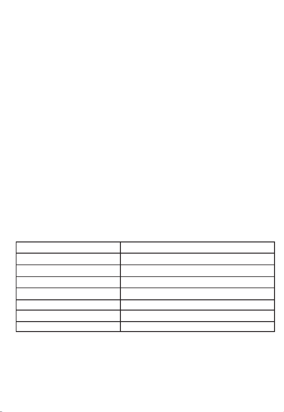
PART NAMES
1
2
4
5
6
7
3
Microwave features
8
FRONT VIEW
1
2
3
4 5 6 7
8
Bottom View
9
10
9
10
Window
Interlock system
Door
assembly
Turntable ring assembly
Tur
ntable
Sha
Turntable
glass
tray
Control
panel
Front vent
grill
Surface lights
Ventilation
lters
Front
Rear
8
Note: 1).If the power level you choose is 100% power, steps "3" and "4" can be skiped
and go directly to the step " 5 ".
2).
Once the cooking is d
one, the buzzer will sound 5 times.
.
For example: to cook the food with 100% microwave power for 10 minutes and then cook
with 80% microwave power for 15 minutes. Do as following:
1) Press "TIME COOK" to choose microwave cooking;
2) Press "1","0","0","0" to input the cooking time;
3) Press "POWER" to choose 100% microwave power;
4) Press "TIME COOK" to choose microwave cooking;
At most two stages can be input.
1. Clock Setting
1). Press "CLOCK/AM/PM",the unit enters the clock setting states.AM indicator will
light.
"0:00" ash to remind you to input the time.
2). Press "CLOCK/AM/PM " again to select AM or PM. e responding AM or PM
indicator lights.
3). Press the number keys and enter the correct time. For example, time is 10:12 now,
press "1,0,1,2" in turn.
4). Press "CLOCK/AM/PM " key to nish setting the clock.
N
o
te: is is a 12 hour clock from 1:00 to 12:59. If the set time is wrong, press
"CLOCK/AM/PM" .The buzzer will sound twice and go back to the waiting state.
OPERATION INSTRUCTIONS
3.Multi-stage Cooking
2. Microwave Cooking
1) Press "
TIME COOK" to select microwave cooking. "0:00" will ash to remind you to
input the cooking time.
2) Press the number keys to adjust the cooking time you need.
For example, to cook the time for 10 minutes, press "1,0,0,0 " in turn.
e maximum cooking time is 99 minutes 99 seconds.
3) At the same time, you can choose the power by pressing "POWER".
4) Press the number keys to select the power level.
5) Press "START/PAUSE" to start cooking. Time counts down.
Ten power levels are available.
Level
Power
Display
10
100%
9
90%
8
80%
7
70%
6
60%
5
50%
4
40%
3
30%
2
20%
1
10%
PL10 PL9 PL8 PL7 PL6 PL5 PL4 PL3 PL2 PL1
9

5) Press "1","5","0","0" to input cooking time;
6) Press "POWER" to select the microwave power;
7) Press "8" to choose 80% microwave power;
8) Press "START" to start cooking.
Note:
a.Microwave cooking can be set as two stages only. Defrost program and auto menu
cannot be set here.
b. When the rst stage nish, buzzer sounds once and the second stage begins cooking.
4. Quick Cooking
1) In waiting states,press " ADD 30 SEC." to start cooking 100% microwave power for
30 seconds.
2) During cooking states, 30 seconds can be increased for each pressing on
"ADD 30 SEC.". e maximum cooking time is 99 minutes and 99 seconds.
3) Press number keys from 1 to 6 to start cooking with full microwave power for
1-6 minutes.
Note: During speedy cooking, microwave power can be checked and selected.
Press"POWER", the current power displays, then press number keys to choose the
power you need
5. Defrost Cooking
A. Defrost By Weight
1) Press "DEFROST AUTO/TIME" once to choose defrost by weight function.
Defrost indicator will light and "lb" indicator ash;
2) Press number keys from 0 to 9 to input the derfost weight.
For example: the food weight is 1.2 Lbs, then "1","2" will be input.
e maximum cooking weight is 6.0 Lbs.If the weight input is more than 6.0 Lbs,
the unit will turn back to waiting state.
3) Press "START/PAUSE" to start defrosting. "lb" indicator will be o.
B. Defrost By Time
1) Press "DEFROST AUTO/TIME" twice to choose defrost by time function. Defrost
indicator will light;
2) Press number keys from 0 to 9 to input the derfost time.
e maximum time can be input is 99 minutes and 99 seconds.
3) Press "START/PAUSE" to start defrosting.
Note: I
f half of the defrost time passes, the buzzer will sound once to remind you to
turn the food over. In both weight/time defrost, the defrost icon is blinking on
screen during the operation to indicate that defrost is being done.
10

Note: During timer states, hood and microwave light can be activated. Other functions
cannot be used.
w
ould be o.
2)
Under the mode of display o, press any key, buzzer sound once, the microwave
10 .
a) Press " POPCORN ", " ", " " or " " repeatedly
b) Press " START/PAUSE " to cook.
6.Hood Function
1) When the exhaust fan is under o states, press " VENT FAN/H/L/OFF " once
to choose the fan with high speed;
2) Press "VENT FAN/H/L/OFF" twice to choose the fan with low speed;
3) Press "VENT FAN/H/L/OFF" three times to choose the fan to be o.
4) Except lock states, the fan can be adjusted anytime.
7.Microwave Light
1) Press "SURFACE LIGHT ON/OFF" once to turn on the light;
2) Press "SURFACE LIGHT ON/OFF" twice to turn o the light.
8.Timer Function
1) Press "TIMER", timer indicator will light;
2) Press number keys to input the cooking time you need.
e maximum cooking time is 99 minutes and 99 seconds.
3) Press "TIMER" and the time will count down. When timer is over, the buzzer will
sound.
4) Press " TIMER", the timer function or the buzzer sound will stop.
is back to waiting mode.
Auto Menu
BAKED PATATO BEVERAGE REHEAT
until the number you wish appears in the display.
9. Display On/Off Function
1) In wating states,press " 0" for 3 seconds,buzzer sounds twice.
An
d the display
11
12. Lock Function For Children
Lock: In waiting state, press " STOP/CLEAR " for 3 seconds, there will be two beeps
denoting the entering into the children-lock state;
Lock release: In locked state, press " STOP/CLEAR " for 3 seconds, there will be two
beeps denoting that lock is released.
11. Inquiring Function
(1) Under microwave cooking states, press " POWER" to check the power level.
(2) During cooking states, press "
CLOCK/AM/PM"to check the clock.
e menu chart:
Menu
Weight
Power
Popcorn
Baked potato
Beverage
Reheat
1.75 Oz
3.0 Oz
3.5 Oz
1
2
3
1
2
3
8.0 Oz
16.0 Oz
24.0 Oz
P100
P100
P100
P100
P100
P100
P100
P100
P100
P100
P100
P100
12

TROUBLE
Oven will not start
POSSIBLE CAUSE POSSIBLE REMEDY
a. Electrical cord for oven is
not plugged in.
b. Door is open.
c. Wrong operation is set.
a. Plug into the outlet.
b. Close the door and try
again.
c. Check instructions.
Arcing or sparking
a. Materials to be avoided in
microwave were used.
b. e microwave is operated
when empty.
c. Spilled food remains in the
cavity.
a. Use microwave-safe cookware
only.
b. Do not operate with microwave
empty.
c.
Clean cavity with wet towel.
Unevenly cooked
foods
a. Use microwave-safe
cookware only.
b. Completely defrost food.
c. Use correct cook time and
power level.
d. Turn or stir food.
Overcooked foods
Cook time or power level is
not suitable.
Use correct cook time or
power level
Undercooked foods
a.
b.
Materials to be avoided in
microwave were used.
Food is not defrosted
completely.
c. Microwave ventilation ports
are
restricted.
d. Cook time or power level
is
not suitable.
a. Use microwave-safe
cookware only.
b. Completely defrost food.
c. Check to see that microwave
ventilation ports are not
restricted.
d. Use correct cook time or
power level.
Improper defrosting
a. Materials to be avoided in
microwave were used.
b. Cook time or power level is
not suitable.
c. Food is not turned or stirred.
a. Use microwave-safe
cookware only.
b. Use correct cook time or
power level .
c. Turn or stir food.
MAINTENANCE
Troubleshooting
Check your problem by using the chart below and try the solutions for each problem. If the
microwave still does not work properly, contact the nearest authorized service center.
a.
b.
Materials to be avoided in
microwave were used.
Food is not defrosted
completely.
c. Cook time or power level is
not suitable.
d. Food is not turned or stirred.
13
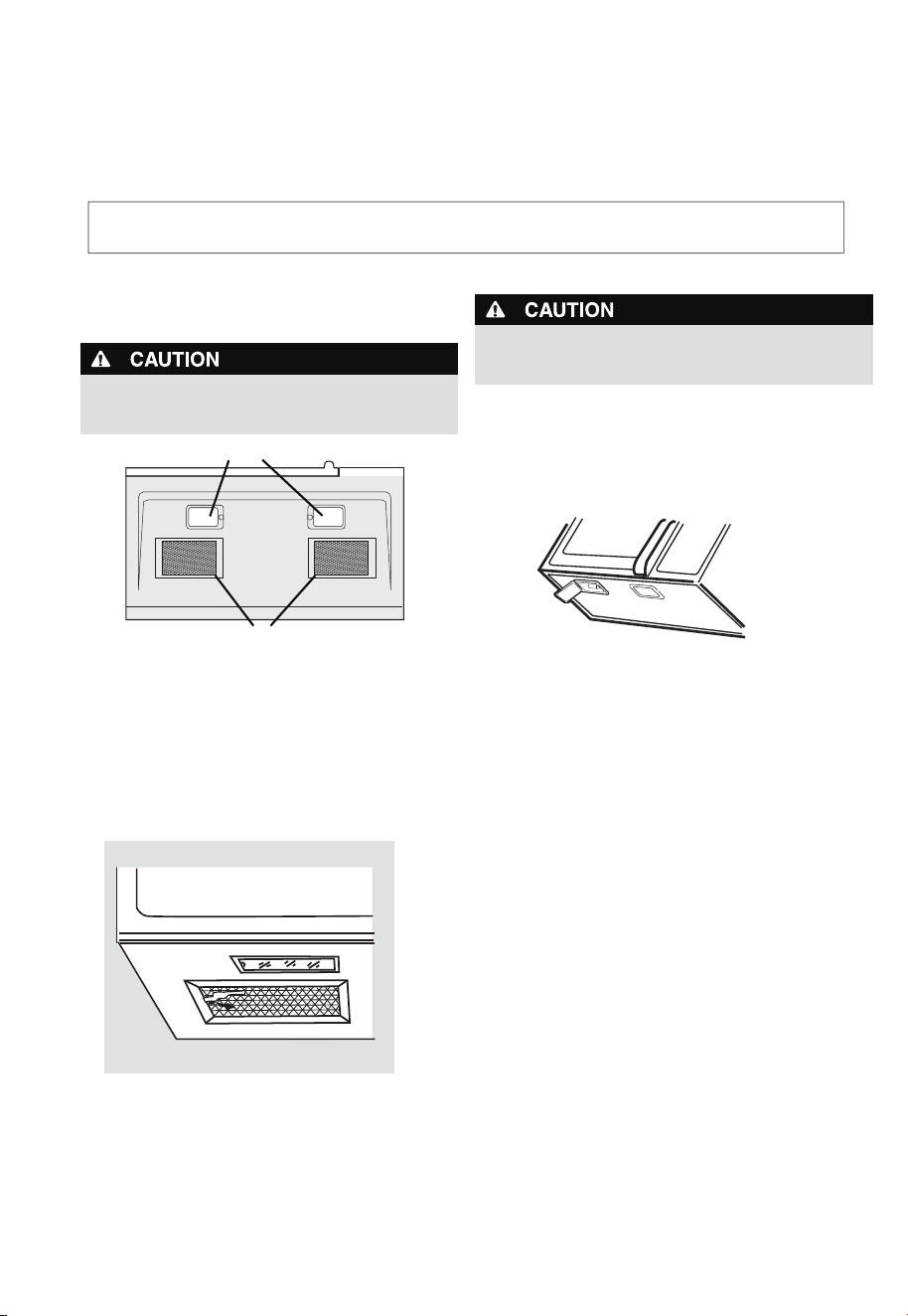
To avoid risk of personal injury or property damage, do
not operate microwave hood w
ithout lters properly in
place.
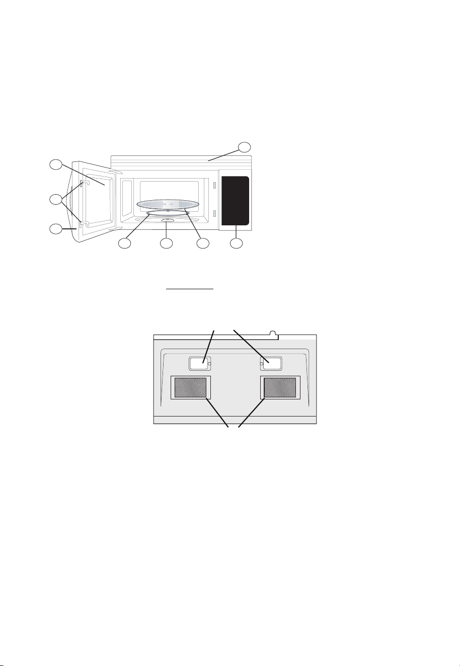
Cleaning the exhaust lters
e microwave ventilation e xhaust lters s hould be
removed a nd cleaned oen; ge nerally at least once
every month.
1. To remove the exhaust ventilation lters, slide the lter
Front
Rear
Surface lights
Ventilation
lters
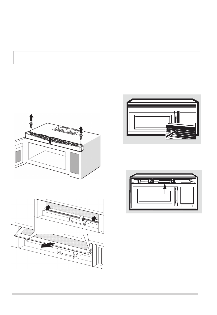
Surface light replacement
To avoid risk of personal injury or property damage, wear
gloves when replacing the light bulbs.
1. Unplug the microwave or turn o power at the main
circuit breaker.
2. Remove the bulb cover mounting screws at both light
positions under the microwave.
3.
Replace bulb with 30 watt appliance bulb.
4.
5. Plug the microwave back into the power supply or turn
the power back on at the main circuit breaker.
Re-install bulb cover and mounting screw.
CLEANING AND CARE
Disconnect the power cord before cleaning or
leave the door open to deactivate the oven during cleaning.
2. To reinstall the exhaust ventilation lter, slide it in the
frame slot on the le/ right of the opening.
Pull up and to the le/ right to lock into place.
to the le/right using the tab. Pull it down and out.
14
2. Remove the vent grill mounting screws.
3. Pull the vent grill away from the unit.
4.Remove the charcoal lter by pushing it inwards,
then turn and pull it away from the unit.
Note: DO NOT USE BULB LARGER THAN
30 WATTS.
CLEANING AND CARE
Charcoal lter replacement
Charcoal Filter installed in your microwave is used
for nonvented, recirculated installation. e lter should
be changed every 6 to 12 months depending on use.
1. Disconnect power to the microwave at the circuit
breaker panel or by unplugging.
per instructions 1-4 above and
1. Remove the grill by taking out the 2 screws that
2.
3. Replace the screw. Connect electrical power
Oven light replacement
Remove the vent grill
charcoal lter, if used.
Disconnect the power cord before cleaning or
leave the door open to deactivate the oven during cleaning.
hold
it in place.
Next, remove the screw located above the door
near the center of the oven that secures the light
housing.
to the microwave.
15

Never use rough scouring powder or pads on the
microwave. Wipe the microwave inside and out with a so
cloth
and and warm (not hot) mild detergent solution.
en rinse and wipe completely dry.
Wipe spatters immediately with a wet paper towel,
especially aer cooking greasy foods like chicken or bacon.
Clean your m icrowave weekly or m ore oen, i f needed.
Follow these instructions to clean and care for your
microwave:
• Keep the insi de (cavity) of the microwave clean. Food
particles and spilled liquids can stick to the walls, causing
the microwave to wor k less eciently.
• Wipe up spills immediately. Use a damp, clean cloth and
mild soap.
DO NOT use harsh detergents or
abrasive cleaners.
• To help loosen baked-on food particles or liquids, heat 2
cups of water (add the juice of 1 lemon if you desire to
keep the oven fresh smelling) in a 4 cup measuring glass at
High power for 5 minutes or until boiling. Let stand in oven
cavity for 1 or 2 minutes.
• Remove th e glass tu rntable tr ay wh en cleaning the
cavity or tray . To prevent the glass t urntable from
breaking, handle with care and do not put it in water
immediately aer cooking. Wash the turntable t ray in
warm sudsy water or in the dish washer.
• Clean the outs ide surface of the micr owave with soap and
a clean damp cloth. Dry with a clean so cloth. To prevent
damage to the opperating parts, do not l et water seep
into any vents or ope nings.
Cleaning suggestions
For best performance and for safety reasons, keep the oven
•
clean inside
and outside. Take special care to keep the
inner door panel and microwave frame free of food and
grease build-up.
Wash the door window with very mild soap and
water. Be sure to use a so clean cloth to avoid
scratching.
• If steam accumulates inside or outside the door, wipe
with a so cloth.
Steam can accumulate when operating
the microwave in high humidity and in no way indicates
microwave l eakage.
• Never operate the oven without food in the oven cavity;
this can damage the magnetron tube or glass tray. You
may wish to leave a cup of water standing inside the
microwave when it is not in use to prevent damage if
accidentally turned on.
CLEANING AND CARE
Disconnect the power cord before cleaning or
leave the door open to deactivate the oven during cleaning.
16

Element Appliance Limited Warranty
(the “Products” or “Product” when referencing a singular product herein)
This Product (including any accessories included in the original packaging) as supplied and
distributed in new condition, is warranted by Element Appliance Company, LLC
("Element") to the original customer who purchases the Product from an authorized
Element retailer (the “Original Customer” or “you”) against defects in material and
workmanship under proper use, maintenance, and care according to the owner’s manual,
warnings, and instructions accompanying the Product (“Warranty”) as follows:
* PLEASE NOTE – Proof of purchase evidencing the date of purchase by the Original
Purchaser from an authorized Element retailer (“Valid Proof of Purchase”) is required
for
all Warranty service. The express Warranty set forth herein is subject to all terms and
conditions set forth below.
1. WARRANTY SERVICE:
A. ONE-YEAR WARRANTY: Except as provided in subpart 1.B below, for a
period of one (1)
year from the date of purchase by the Original Customer (the “Warranty Period”), if
the parts or components covered by this Warranty are determined by Element or
Element’s authorized service provider to be defective in material or workmanship,
Element will, at its sole and absolute discretion and option: (i) repair the defective part or
component at no charge to the Original Customer, (ii) replace the defective Product with a
new Product of similar or better quality, at no charge to the Original Customer, or (iii)
refund the documented purchase price paid by the Original Customer (excluding tax) to
the Original Customer upon return of the defective Product as directed by Element. After
the Warranty Period expires, the Original Customer must pay for all parts, components,
shipping and handling, labor, and replacement costs associated with the Product or any
part or component thereof, regardless of any defects in the Product or any part or
component thereof.
B. LIMITED EXTENDED WARRANTY THROUGH PRODUCT REGISTRATION: If
and only if the Original Customer registers the Product at www.elementelectronics.com
within ninety (90) days of the date of purchase by the Original Customer, then the
Warranty Period discussed in subpart 1.A. above shall be extended an additional one (1)
year to a new Warranty Period equaling two (2) years from the date of purchase by the
Original Customer. If the Product is not registered as provided for in this subpart 1.B, then
the standard one-year Warranty Period set forth in subpart 1.A shall apply.
C. TIMING AND PROCEDURE: Before Warranty service can commence,
the Original Customer must contact either (i) the retailer from whom the Original
Customer purchased the Product, o
r (ii) Element directly, in either case for problem
determination and service procedures. Valid Proof of Purchase evidencing that the
Product is within the Warranty Period MUST be presented by Original Customer in
order to obtain the requested Warranty service. Please have your model and serial
number available, along with your date of purchase of the Product. To remain eligible
for Warranty service, Original Customer may not return the Product or any part or
component thereof to the retailer or Element without Element’s prior written consent.
17

2. EXCLUSIONS AND LIMITATIONS TO WARRANTY SERVICE
The Warranty covers manufacturing defects in materials and workmanship of the Product
encountered in the normal, non-commercial use of the Product, and does not cover (a)
damages or malfunctions resulting from improper or unreasonable use or maintenance,
abuse, negligence, failure to follow instructions contained in any written materials
that accompany the Product, deterioration by reason of excess moisture, corrosive
atmosphere, lightning, power surges, connections to improper voltage supply,
unauthorized alteration, or other external causes such as extremes in temperature
or humidity, modifications, scratches or discoloration; (b) any damage caused by using
non-authorized parts or service facilities for repair of Products (however, for avoidance of
doubt, using non-authorized parts or service facilities will not, in and of itself, void the
Warranty); (c) transportation, shipping, delivery, pickup, insurance, installation, or set-
up costs; (d) ordinary wear and tear, cosmetic damage, or damage due to acts of nature,
including but not limited to, water, floods, wind, storm, tornado, earthquake, or fire, or
due to damage caused by extraordinary impact events, such as dropping, crushing,
demolition or other extraordinary damage; (e) commercial use of the Product, or use of
the Product for anything other than single-family household or residential use; or (f)
modification of the Product or any part of the Product.
This Warranty is made to the Original Customer only and does not cover Products sold AS
IS or WITH ALL FAULTS. The Warranty is invalid if the factory-applied serial number has
been altered or removed from the Product. This Warranty is valid only in the United
States, and only applies to Product if it was purchased and serviced in the United States.
The addition of equipment or features to the Product that are not manufactured or
recommended by Element could affect the intended function of the Product, and
therefore may void the Warranty. Furthermore, the exposure of the Product to chemicals,
heat, cold, humidity, or other elements can affect the Product components, and therefore,
the Warranty does not cover discoloration, fading, cosmetic changes, rust, or any
damages or failure related to any such items. The Warranty is contingent upon the
proper use, maintenance, and care of the Product. The Warranty may be void if the
Product has been used in a manner contradictory to, or in violation of, the terms of the
user’s manual, warnings, or instructions accompanying the Product.
THIS WARRANTY IS MADE IN LIEU OF AND SUPERSEDES ALL OTHER WARRANTIES OR
CONDITIONS OF MERCHANTABILITY OR FITNESS FOR A PARTICULAR PURPOSE OR
GENERAL USE, WHETHER EXPRESS, IMPLIED, COLLATERAL, STATUTORY, OR PROVIDED
BY COMMON LAW, THE UNIFORM COMMERCIAL CODE, OR OTHERWISE. ELEMENT
FURTHER DISCLAIMS ALL WARRANTIES AFTER THE END OF THE WARRANTY TERM
DEFINED ABOVE. NO OTHER EXPRESS WARRANTY OR GUARANTY GIVEN BY ANY
OTHER PERSON, FIRM, OR ENTITY WITH RESPECT TO THE PRODUCT SHALL BE BINDING
ON ELEMENT. REPAIR, REPLACEMENT, OR REFUND OF THE ORIGINAL PURCHASE
PRICE, AT ELEMENT’S SOLE DISCRETION, ARE THE EXCLUSIVE REMEDIES OF THE
CUSTOMER.
ELEMENT SHALL NOT BE LIABLE FOR ANY INCIDENTAL OR CONSEQUENTIAL DAMAGES
CAUSED BY THE USE, MISUSE, OR INABILITY TO USE THE PRODUCT. THESE INCLUDE,
BUT ARE NOT LIMITED TO, ANY DAMAGES IN THE FORM OF LOST PROFITS, LOSS OF
USE, LEGAL FEES, ECONOMIC LOSS, PERSONAL INJURIES, OR ANY OTHER DAMAGES
CAUSED BY CIRCUMSTANCES BEYOND THE CONTROL OF ELEMENT.
NOTWITHSTANDING THE FOREGOING, ELEMENT’S AGGREGATE LIABILITY TO ANY
CUSTOMER SHALL NOT EXCEED THE ORIGINAL PURCHASE PRICE OF THE PRODUCT.
THIS WARRANTY SHALL NOT EXTEND TO ANYONE OTHER THAN THE ORIGINAL
CUSTOMER WHO PURCHASED THE PRODUCT, AND IS NOT
18

TRANSFERRABLE. NO PERSON IS AUTHORIZED TO ALTER, EXTEND, OR WAIVE THIS
WARRANTY OR ANY OF ITS TERMS OR CONDITIONS.
Some states do not allow the exclusion or limitation of incidental or consequential
damages, or allow limitations on warranties, so the above limitations or exclusions may
not apply to you. This Warranty gives you specific rights, and you may have other rights,
which vary from state to state. The exclusions and limitations to the Warranty apply to
the maximum extent permitted by law and unless restricted or prohibited by law.
Where any term of this Warranty is prohibited by applicable law, it shall be null and void,
but the remainder of this Warranty shall remain in effect.
PLEASE DIRECT ALL CORRESPONDENCE TO:
Element Appliance Company, LLC
(888) 842-3577
https://elementelectronics.com
19

Element, the Element Logo, and Bring it home are trademarks of Element Brand Holding, LLC.
All other trademarks are the property of their respective owner, who has not sponsored, endorsed,
or approved this product. ©2023 Element Appliance Company, LLC. All rights reserved.
Distributed by Element Appliance Company, LLC
Augusta, GA 30909
For service, support and warranty information:
Call 888.842.3577, email us at [email protected] or visit
www.elementelectronics.com
READ CAR
EFULLY.
KEEP THESE
INSTRUCTIONS.
Installation
Instructions
Over the Range
Microwave
• IMPORTANT – Save these
instructions for local inspector’s use.
• IMPORTANT – Observe all
governing codes and ordinances.
• Note to Installer – Be sure to
leave these
instructions with the Consumer.
BEFORE YOU BEGIN
Read these instructions completely and carefully.
• Note to Consumer – Keep these
instructions for future reference.
• Skill level – Installation of this appliance requires
basic mechanical and electrical skills.
• Proper installation is the responsibility of the
installer.
Before You Use Your Microwave
CONTENTS
General information
Important Safety Instructions ......................... 3
Electrical Requirements ................................. 3
Damage – Shipment/Installation...................... 4
Parts Included................................................. 4
Tools You Will Need ........................................ 5
Mounting Space ............................................. 5
Step-by-step installation guide
6–8
Removing the Mounting P
late .................
6
Finding the Wall Studs ............................ 6
Determining Wall Plate Location .............. 7
Aligning the Wall Plate ........................... 8
Outside Top Exhaust
Attach Mounting Plate to Wall ........12
Preparation of Top Cabinet .............13
Checking for Proper Damper
Adapting Microwave Blower
A
B
C
Installation Instructions
21
20
Recirculating .................................20
Mount the Microwave ...........19
Preparation of Top Cabinet ............17
Attach Mounting Plate to Wall ........17
Outside Back Exhaust.....................16
Connecting Ductwork......................15
Adjust the Exhaust Adaptor ............15
Operation.......................................14
Outside Back Exhaust....................... 16–19
Adapting Microwave Blower for
Outside top Exhaust
.............. 13–14
Placement of The Mounting Plate ..............
......................... 12–15
Preparing Rear Wall for
Remove Blower Plate ........................16
Installing or Change
the
Charcoal Filter
Preparation of Top Cabinet ............20
Check Blower Plate .....................
.................... 23
..........................22
Attach Mounting Plate to Wall.......
22
–22
Installation Types....................................... 9–22
for Outside Back Exhaust...........17
–
18
Mount the Microwave ....21
–
Hood Exhaust ............................................ 10–11
Mount the Microwave ......14
–
15
2
........
.... ....
.........
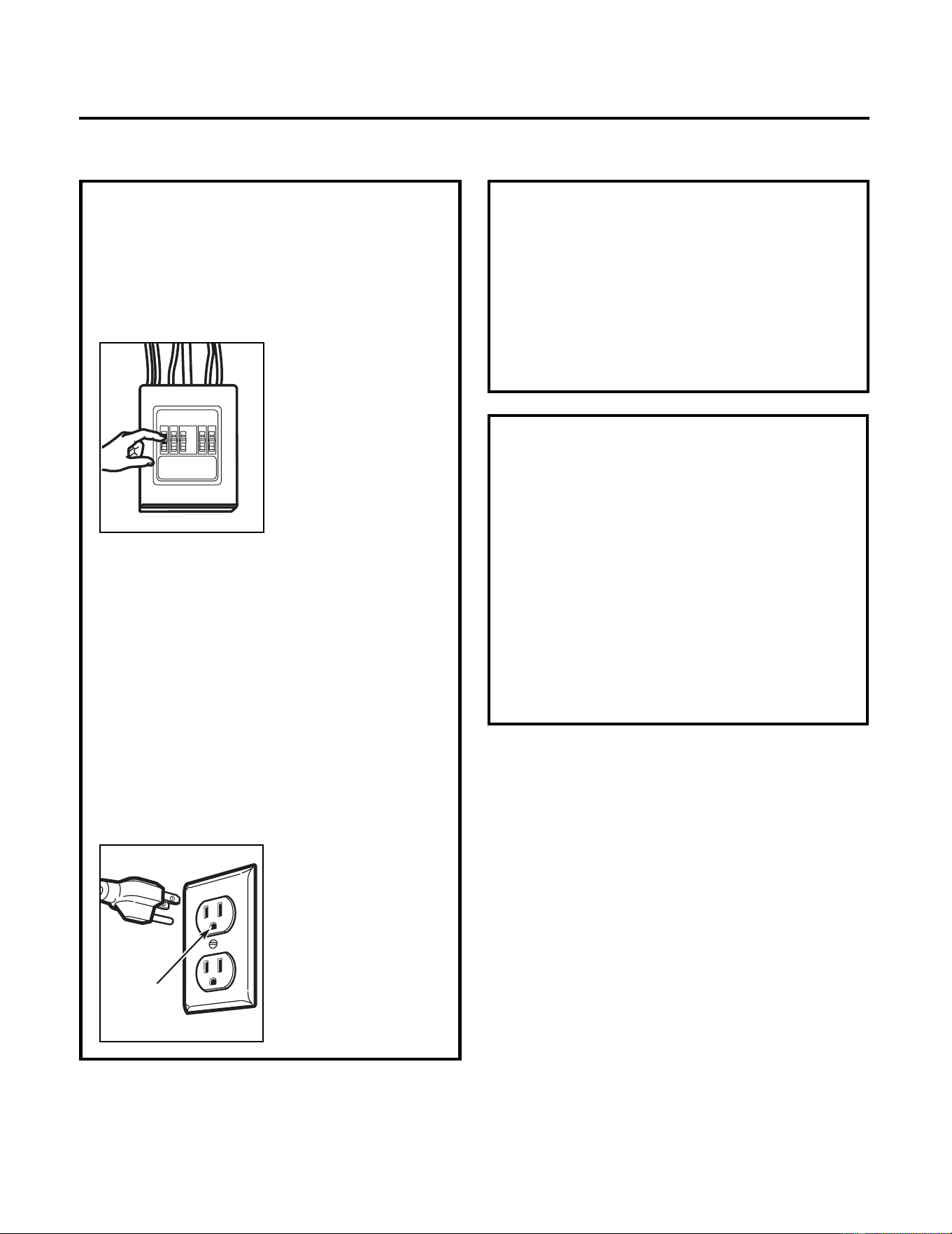
This product requires a three-prong grounded
outlet. The installer must perform a ground
continuity check on the power outlet box before
beginning the installation to insure that the outlet
box is properly grounded. If not properly grounded,
or if the outlet box does not meet electrical
requirements noted
(under ELECTRICAL REQUIREMENTS), a qualified
electrician should be employed to correct any
deficiencies.
CAUTION: For personal
safety, remove house
fuse or open circuit
breaker before
beginning installation to
avoid severe or fatal
shock injury.
CAUTION: For personal safety, the mounting
surface must be capable of supporting the cabinet
load, in addition to the added weight of this 63–85
pound (28.5–38.5 kg) product, plus additional loads
of up to 50 pounds (22.7 kg) or a total weight of
113–135 pounds (51.3–61.2 kg).
CAUTION: For personal safety, this product cannot
be installed in cabinet arrangements such as an
island or a peninsula. It must be mounted to BOTH
a top cabinet AND a wall.
NOTE: For easier installation and personal safety, it
is recommended that two people install this
product.
IMPORTANT – PLEASE READ CAREFULLY. FOR
PERSONAL SAFETY, THIS APPLIANCE MUST BE
PROPERLY GROUNDED TO AVOID SEVERE OR
FATAL SHOCK.
The power cord of this
appliance is equipped with
a three-prong (grounding)
plug which mates with a
standard three-prong
(grounding) wall
receptacle to minimize the
possibility of electric
shock hazard from this
appliance.
You should have the wall receptacle and circuit
checked by a qualified electrician to make sure the
receptacle is properly grounded.
Where a standard two-prong wall receptacle is
encountered, it is very important to have it
replaced with a properly grounded three-prong
wall receptacle, installed by a qualified electrician.
DO NOT, UNDER ANY CIRCUMSTANCES, CUT,
DEFORM OR REMOVE ANY OF THE PRONGS FROM
THE POWER CORD.
DO NOT USE WITH AN
EXTENSION CORD.
IMPORTANT SAFETY INSTRUCTIONS
ELECTRICAL
REQUIREMENTS
Product rating is 120 volts AC, 60 Hertz, 15 amps
and 1.6 kilowatts. This product must be
connected to a supply circuit of the proper
voltage and frequency. Wire size must conform to
the requirements of the National Electrical Code
or the prevailing local code for this kilowatt
rating. The power supply cord and plug should be
brought to a separate 15- to 20- ampere branch
circuit single grounded outlet. The outlet box
should be located in the cabinet above the
microwave. The outlet box and supply circuit
should be installed by a qualified electrician and
conform to the National Electrical Code or the
prevailing local code.
Ensure proper
ground e
xists
before use
Installation Instructions
3
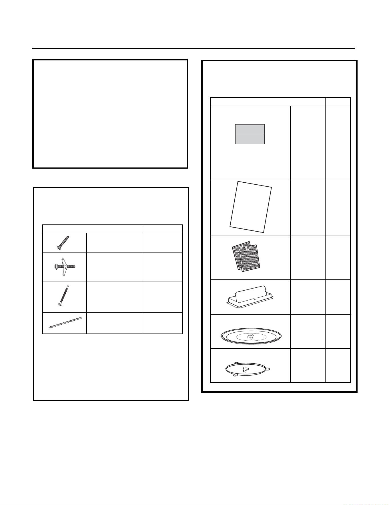
PART QUANTITY
2Wood Screws
(
1
⁄4" x 2")
Toggle Bolts
(and wing
nuts) (
3
⁄16" x 3")
3
Self-Aligning
Machine Screws
(
1
⁄4"
x
3
1
⁄4")
Nylon Grommet
(for metal
cabinets)
1
• If the unit is damaged in shipment, return the
unit to the store in which it was bought for
repair or replacement.
• If the unit is damaged by the customer,
repair or replacement is the responsibility of
the customer.
• If the unit is damaged by the installer (if
other than the customer), repair or
replacement must be made by arrangement
between customer and installer.
DAMAGE—SHIPMENT/
INSTALLATION
Installation Instructions
You will find the installation hardware contained
in a packet with the unit. Check to make sure
you have all these parts.
NOTE: Some extra parts are included.
PARTS INCLUDED
HARDWARE PACKET
PART
QUANTITY
Template
1
Wall
Template
Installation 1
Instructions
Separately 2
Packed
Filters
INSTALLATION
INSTRUCTIONS
PARTS INCLUDED (CONT.)
ADDITIONAL PARTS
1
adaptor
Grease
Exhaust
Glass 1
Tray
1
Ring
Turntable
Top Cabinet
Combined
and Rear
2
4
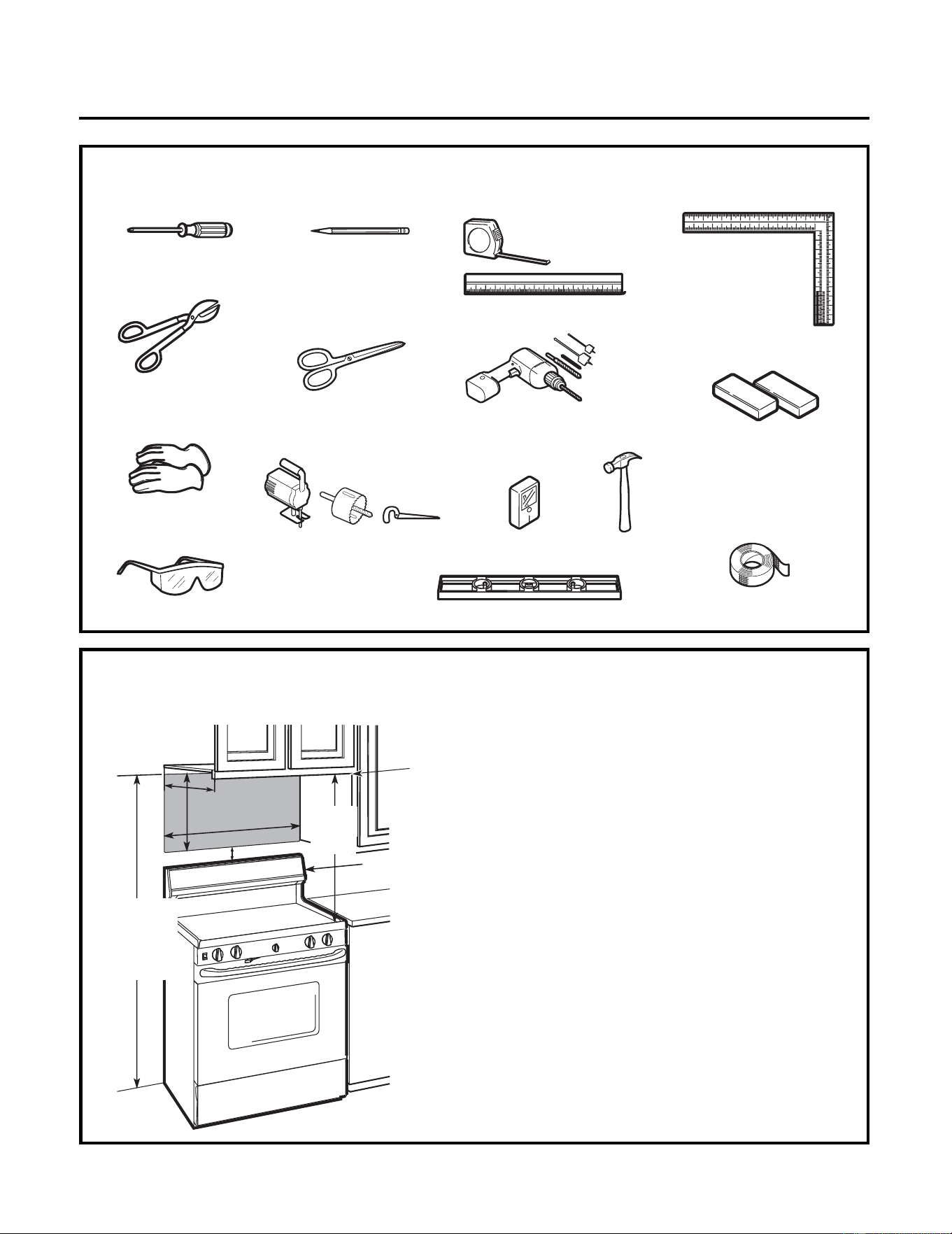
TOOLS YOU WILL NEED
# 1 Phillips screwdriver
Pencil
Ruler or tape
measure and
straight edge
Carpenter square
(optional)
Tin snips (for
cutting damper,
if required)
Electric drill with
3
⁄16",
1
⁄2"
and
5
⁄8" drill bits
Stud finder or
Hammer (optional)
Filler blocks or
scrap wood pieces,
if needed for top
cabinet spacing
(used on recessed
bottom cabinet
installations only)
Gloves
Saw (saber, hole or keyhole)
Level
Duct and masking tape
MOUNTING SPACE
NOTES:
•
•
•
Bottom Edge of
Cabinet Needs to
be 30w (76.2 cm)
or More from the
Cooking Surface
Installation Instructions
Scissors
(to cut template, if
necessary)
Safety goggles
Backsplash
66
"(167.6 cm)
or More from
the Floor to
the Topofthe
Microwave
30" (76.2 cm)
2"(5.1
cm)
30
"
(76.2 cm)
min.
16
1
⁄2" (41.9 cm)
13"Maximum (33 cm)
The space between the cabinets must be
30" (76.2 cm) wide and free of obstructions.
If you are going to vent your microwave to
the outside, see Hood Exhaust Section for
exhaust duct preparation.
When installing the microwave beneath
smooth, flat cabinets, be careful to follow the
instructions on the top cabinet template for
power cord clearance.
As a guide to installation, see page 24 for
Mounting Template Information.
5
Screws
Screws
Mounting Plate
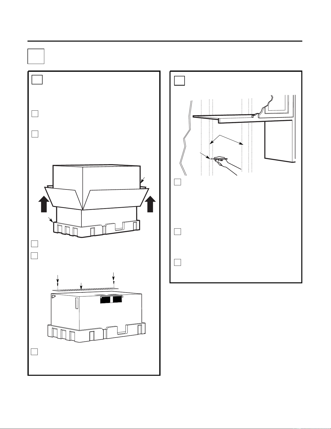
Find the studs, using one of the
following methods:
A. Stud finder – a magnetic device which
locates nails.
OR
B. Use a hammer to tap lightly across the
mounting surface to find a solid sound.
This will indicate a stud location.
After locating the stud(s), find the center by
probing the wall with a small nail to find the
edges of the stud. Then place a mark halfway
between the edges. The center of any adjacent
studs should be 16" (40.6 cm) or 24" (61 cm)
from this mark.
Draw a line down the center of the studs.
THE MICROWAVE MUST BE CONNECTED TO
AT LEAST ONE WALL STUD.
1
REMOVING THE
MICROWAVE OVEN FROM
THE CARTON/REMOVING
THE MOUNTING PLATE
FINDING THE WALL STUDS
B
.
A
.
2
PLACEMENT OF THE MOUNTING PLATE
1
Wall
Studs
Center
3
Carton
Pull the carton up and off the microwave.
Remove the screws from the mounting
plate. This plate will be used as the rear
wall template and for mounting. Reinstall
the screws into the holes where they were
removed.
2
Styrofoam
Installation Instructions
3
5
4
1
Remove the installation instructions, filters,
glass tray and the small hardware bag.
Do not
remove
the Styrofoam protecting the front of
the
oven.
Fold back all 4 carton flaps fully against carton
sides. Then carefully roll the microwave and
carton over onto the top side.
The microwave should be resting in the
Styrofoam.
Cut the middle of the outer protective plastic
bag to remove
the m
ounting
p
late
6
WALL PLATE LOCATION UNDER YOUR CABINET
C.
DETERMINING
Installation Instructions
Draw a line on the
back wall equal to
the depth of the
front overhang.
30"to Cooktop
C
L
3
/
8
"
TO
ED
GE
%#
7
6+
1
0
Ä
+
(
'
:
*
#
75
6
#&#
2
614
+5
2
1
5
+6+10
'
&
1765
+&'
4
'
%1
/
/
'
0
&'
&
&
+
/
'
05
+
10
)4
'
#5
'
Ä
.#&
'
0
#+
4
9
+
..
&+
5
%*
#
4
)'
+0
61
*1
7
5
'
5
64
7%
67
4
'
/+0+
/
7
/
9+
&
6*
4'
37+4
'&
4'#49#..6'/2
.#
6'
NOTE
:
I
T
I
S
V
E
R
Y
IMP
OR
T
A
N
T
T
O
RE
AD
A
N
DF
OLL
O
W
T
H
E
D
IR
E
C
T
ION
S
IN
T
H
E
INS
T
A
L
L
AT
ION
IN
S
T
R
U
C
T
ION
S
B
E
F
O
R
E
P
R
OC
EE
DING
W
I
TH T
H
I
S
R
E
A
R
WA
L
L TE
M
P
L
A
T
E
.
T
h
is
R
e
a
r
W
a
ll
T
e
m
p
lat
e
s
e
r
v
e
st
o
p
osit
io
n
t
h
e
b
o
t
t
o
m
m
o
u
n
t
i
n
g
p
la
t
e
a
n
d
t
o
l
o
c
at
e
th
e
h
or
iz
o
nt
a
l
e
x
h
a
u
st
o
u
t
l
e
t
.
1
.
U
se
a
le
v
e
l
t
o
c
h
e
c
k
t
h
a
t
t
h
e
t
e
m
p
la
t
e
is
p
o
s
ition
e
d
a
cc
u
rat
e
ly
.
2
.
L
o
c
a
t
e
a
n
d
m
a
rka
t
le
a
sto
n
e
studo
n
t
h
elef
t
o
r
ri
gh
t
s
i
d
e
oft
h
e
c
e
n
te
r
l
i
n
e.
01
6
'
Itisim
p
o
r
ta
n
t
t
o
u
s
e
a
tle
a
st
o
n
e
w
oo
d
s
cre
w
m
o
un
t
e
d
f
i
r
mly
in
a
s
t
u
d
t
o
su
p
p
o
r
t
t
h
ew
e
ig
h
t
o
f
t
h
em
i
c
r
o
wa
v
e
.
M
a
r
ktw
o
a
dd
i
t
i
o
n
a
l,
e
v
en
ly
s
pa
c
e
d
loca
t
io
n
sf
o
r
th
e
s
u
pp
lie
dto
g
g
le
b
o
l
ts
.
3
.
D
ril
l
ho
le
s
int
h
e
m
a
r
k
e
d
lo
c
a
t
io
n
s.
W
h
e
r
et
h
e
re
is
a
s
tu
d
,
d
r
ill
a
3
/
1
6
"
h
o
lef
o
r
w
o
o
d
s
c
r
e
w
s
.
F
o
r
h
o
les
th
a
t
d
o
n
o
t
l
i
n
e
u
p
w
ith
a
s
t
u
d
,
d
ril
l
5
/
8
"h
o
l
e
s
for
to
g
g
l
e
b
o
lt
s
.
01
6
'
D
O
N
OT
I
N
S
T
A
L
L
T
H
E
MOU
N
T
I
N
G
P
L
A
T
E
A
T
T
H
I
S
T
I
M
E
.
4
.
R
e
m
ov
et
h
e
t
e
m
p
l
a
t
efro
m
t
h
er
ea
r
w
al
l.
5
.
R
e
v
i
e
w
t
he
In
s
ta
l
la
ti
o
n
I
n
s
t
r
u
c
t
i
o
n
b
o
o
kf
o
r
yo
u
r
i
n
s
t
a
lla
t
io
n
s
i
t
u
a
t
io
n.
L
o
c
a
t
e
a
n
d
ma
r
k
h
o
l
e
s
to
a
lign
w
i
th
h
o
le
si
nth
e
mo
u
n
t
i
ng
p
la
t
e
.
IMP
OR
T
A
N
T
:
L
O
CAT
EA
T
L
E
A
S
T
O
NE
S
T
U
D
O
N
E
I
T
H
E
R
S
ID
EOF
T
H
E
C
E
N
T
E
R
L
I
N
E
.
MAR
KT
H
E
L
O
C
A
T
ION
F
OR
2A
D
DI
T
I
ONA
L
,
E
V
E
N
L
Y
S
P
AC
E
D
T
O
GG
L
EB
OL
T
S
I
NT
H
E
MO
UN
T
IN
G
P
L
A
T
E
A
R
E
A
.
L
o
ca
te
a
n
d
ma
r
k
h
o
l
e
s
toa
li
g
n w
i
t
h
h
o
l
e
s
in
t
h
e
mo
u
n
t
i
n
g
p
l
a
t
e
.
IMP
O
R
T
A
N
T
:
L
O
C
A
T
E
A
T
L
E
A
S
T
ONES
T
U
D
ONEIT
H
E
RS
ID
E O
F
T
H
ECE
N
T
E
R
L
INE
.
MAR
K
T
H
E
L
O
C
A
T
ION
FOR
2
A
DD
I
T
I
ON
A
L
,
E
V
E
N
L
Y
S
P
AC
E
D T
O
GG
L
E
B
OL
T
SINT
H
E
M
O
UN
T
IN
G
P
L
A
T
E
A
R
E
A
.
T
r
im th
e
r
e
a
r
w
a
ll
te
m
p
l
a
t
e
alon
g
t
h
e
d
o
tte
d
l
in
e
.
T
r
im
th
e
r
e
a
r
wal
l
te
mp
la
tea
l
o
n
g
t
h
e
d
o
tted
l
ine
.
%
#
$
%
&
(%76
17
6(14
*
14+
<
1
06#.
1765+&'':*
#7
56
%
7
6
*
1
.
'
6
*
4
1
7)
*
4
'
#4
9
#
.
.
(
14
'
:
*#
7
5
6#&
#
2
61
4
1
2
"
4
"
D
a
r
l
e
v
u
e
l
t
a
a
l
a
hoja
p
a
raco
n
sul
t
a
r
la
ve
r
s
i
ón
e
n
E
s
p
a
ñ
o
l.
3/8
"
TO EDGE
%#76
+
10
Ä
+
(
':
*#75
6
#
6
14
+5215+
6
+10'
&
1
76
5+
&'
4'%1
//
'0&'&
&+
/'
05
+1
0
)4'
#5'Ä.#&'
0
#
+
4
9
+.
.
&+
5
%*#4
)'
+
06
1
*1
75
'
5
6
4
7%
6
74'
/+0+/
7/
9+&6*4
'37+4
'&
4'#49#..6'/2.#6'
NO
TE:
I
T
IS VERY
IMPOR
T
AN
T T
O
READ A
ND
FO
L
LO
W
T
H
E D
IR
EC
TI
O
NS
I
N
T
HEINST
ALLAT
IO
NIN
STR
UC
TI
O
N
S
BEFOR
E
PR
O
CEED
IN
GWITH T
H
IS
REAR
WAL
L TEMPL
ATE.
This R
e
a
r
W
a
ll Te
mpla
te se
r
v
es
to
po
sitio
n
th
e
b
o
tto
m
mo
untin
g
p
la
t
e
a
n
d
t
o
l
o
c
at
e
th
e ho
r
iz
o
n
ta
l e
x
h
aus
t
ou
tle
t.
1
.
U
s
e
alev
el to
c
heck
tha
t
th
e
te
mp
lat
e isp
o
sitio
n
e
d
a
cc
u
r
a
tely
.
2
.L
o
c
a
te
a
n
d
mar
k
a
t le
a
s
t
o
n
e
s
t
u
d
o
n
t
he
le
f
t
o
r
rig
ht
s
ide
o
f
th
e c
e
n
te
rl
ine.
016
'
It
is
i
m
p
o
r
ta
n
t t
o
u
s
e a
t le
a
s
t o
n
e
w
o
o
d
s
c
r
ew
mo
u
n
t
e
d
f
ir
mly
in a
s
tu
d
to
s
u
ppo
r
t t
h
e
w
e
ight
of
th
e
mic
r
o
w
a
v
e
.
Ma
rk
t
wo
a
dditio
nal, e
v
enl
y
s
p
a
ce
d
loc
a
tio
n
s
f
o
r
th
e
s
upp
lie
d t
ogg
le
b
o
lts
.
3.
D
r
ill h
ole
s in
t
h
e
mar
k
ed lo
ca
tio
n
s
.
W
her
e th
e
r
e is
as
tu
d
, d
rill
a
3
/1
6"
ho
le
fo
r
w
o
od
s
cr
e
w
s
.
Fo
r
h
o
le
s
th
a
t d
o no
t lin
e
u
p
w
ith
a
s
t
u
d,
d
r
ill 5
/
8" h
o
le
s for
tog
g
le b
o
lts
.
016
'
D
O
NO
T
INSTA
L
L
T
H
EMOUNTIN
G
P
L
ATE
AT
TH
IS TIME
.
4
.
R
e
m
o
v
e
th
e
te
mp
la
te
fr
om
th
e
re
a
r
w
all.
5
.
R
e
vie
w
t
he
In
s
t
a
ll
atio
n
Instru
c
tio
n
bo
o
k fo
r
y
our
in
stalla
tio
n
s
itu
a
tio
n.
Lo
catean
d
ma
rkh
ol
es t
o al
i
g
n w
i
t
h
h
ol
e
s
i
n th
e
mounti
n
g
pl
a
te
.
I
M
PO
R
T
ANT
:
LOC
A
TE ATLEAST
ON
E STU
D
ON
EITH
ERSI
DE
OF
TH
E C
ENT
ER
LIN
E.
MAR
KTH
E
LOCATIO
NFOR
2 AD
D
IT
IONAL
, EVEN
L
Y
SPACED TOGGLE
BO
L
TS
I
N
THEM
OU
N
T
I
N
G
PLATE
AREA
.
Lo
cate
an
dma
rk
hol
es to al
ig
n w
i
t
hhol
e
s
in t
he
moun
ting pl
a
t
e.
IMPO
R
T
ANT:
LOC
AT
E AT
LEASTON
E ST
U
D
ON EI
T
H
ER
SIDE
OF
THE
C
EN
TE
R
LIN
E.
MAR
K
T
H
E
LO
C
ATIO
N
FO
R2
ADD
ITIONAL
, EVEN
L
Y
SPA
C
ED
TO
GGLEBO
L
T
S
IN
TH
EMO
UNTIN
GP
L
AR
EA.
Trim
ther
e
ar
wall
t
emplate
a
long
the
d
otted
l
i
ne.
Trim
th
e
r
ear
wal
l
tem
platealong
th
e
dottedli
ne.
%
$
&
(%76176(14*14+<1
06#.
1765+&'':*#756
%76
*1.
'
6*417)
*
4'
#49#
.
.
(
1
4'
:
*#756#&#
26
1
4
12
"
4"
D
arle
vu
el
ta
a
lah
o
ja
p
a
r
a
c
o
nsult
a
r
la
v
e
r
si
ó
n
e
n
E
s
p
añ
ol.
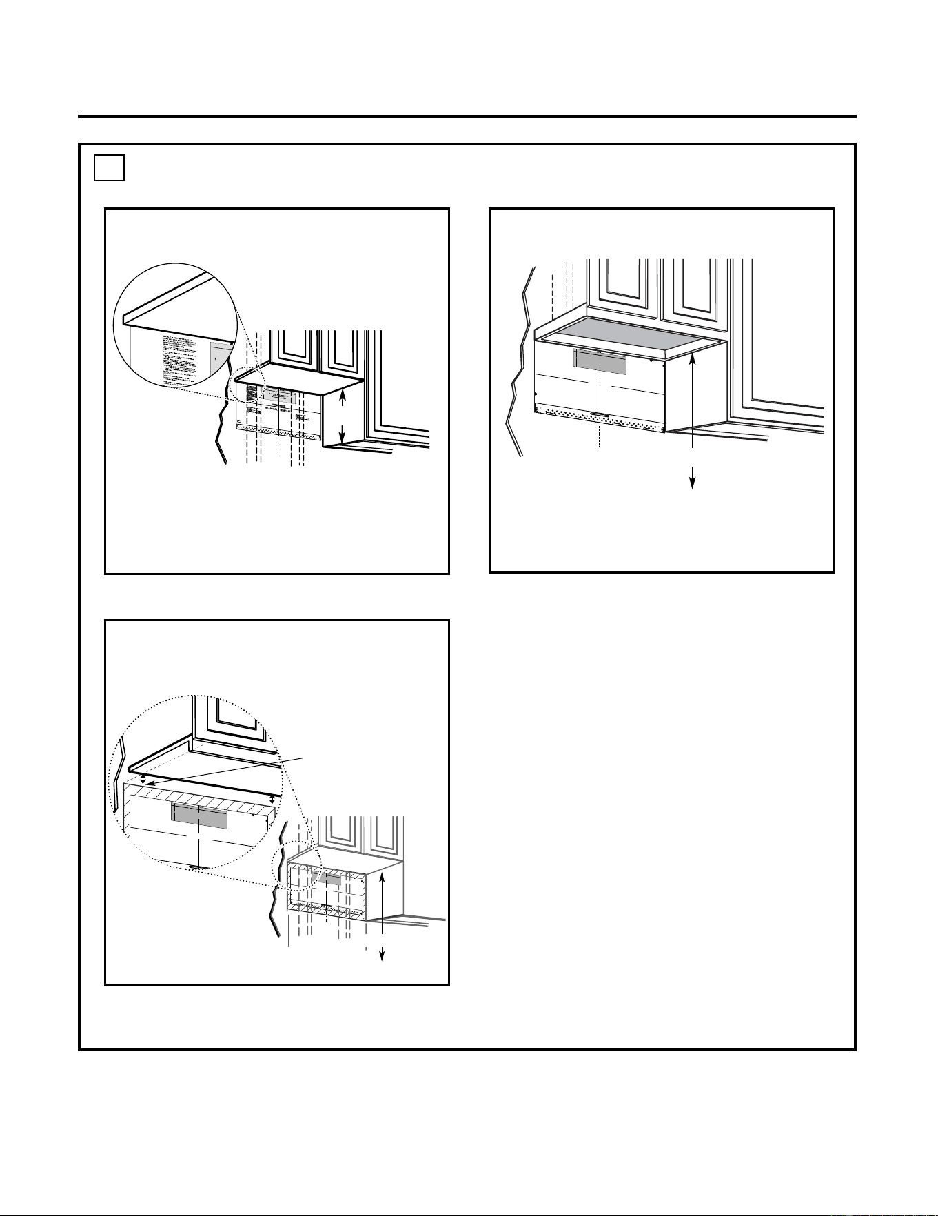
Your cabinets may have decorative trim that
interferes with the microwave installation. Remove
the decorative trim to install the microwave
properly and to make it level.
THE MICROWAVE MUST BE LEVEL.
Use a level to make sure the cabinet bottom is
level.
If the cabinets have a front overhang only, with no
back or side frame, install the mounting plate down
the same distance as the front overhang depth.
This will keep the microwave level.
1.Measure the inside depth of the front
overhang.
2.Draw a horizontal line on the back wall an
equal distance below the cabinet bottom as
the inside depth of the front overhang.
3.For this type of installation with front
overhang only, align the mounting tabs with
this horizontal line, not touching the cabinet
bottom as described in Step D.
30" to Cooktop
Draw a vertical line on the wall at the center of
the 30" space.
Tape the Rear Wall Template onto the wall
m
atching the centerline and touching the
bottom cabinet frame.
C
L
3/8
"
TO
ED
G
E
%
#
7
6
+
10
Ä
+
(
'
:
*#7
56
#&#
2
6
14
+
5
2
1
5
+
6+
10
'
&
1
76
5
+
&
'
4
'
%
1
/
/'0&
'
&&
+/
'05
+
10
)
4'
#
5'Ä
.
#
&'0
#
+
4
9
+
..
&
+
5
%*#
4)'
+
0
61
*
175
'
5
64
7
%674
'
/+0+/7/9+&6*
4'
3
7+4'&
4'#49#..6'/2.#6'
NOT
E:I
TI
S
VE
R
Y
I
M
PO
RTA
N
T
T
O
RE
A
DAND F
O
L
L
O
W
T
HE
D
IRECTIO
NS
INT
H
E
INS
TALLA
TION
IN
S
T
R
UC
T
IO
N
S
BE
F
O
R
E
P
RO
C
E
E
D
INGWI
T
H
T
HI
S
REA
R
WA
LL
T
EM
P
LA
T
E
.
T
h
i
s
R
ea
rW
a
l
l
T
e
m
pl
a
t
e
s
er
v
e
s
to
p
o
s
i
t
io
n
t
he
bo
t
t
om
mo
u
n
t
i
n
g
pl
ate
a
n
d
t
o
l
oc
at
et
h
eho
r
i
z
o
n
t
a
l
ex
h
a
u
s
t
ou
t
le
t
.
1.
Us
e
al
e
ve
l
t
o
c
h
e
c
k
t
hat
t
h
e
templatei
s
p
o
si
t
i
o
n
e
d
a
c
cu
r
a
tely.
2
.
L
oc
a
t
e
a
n
d
ma
r
k
a
t
l
ea
st
on
e
s
t
ud
o
n
t
h
e l
ef
t
o
r
r
i
g
h
t
sid
eo
f
t
h
e
c
e
nt
e
r
l
in
e
.
01
6
'
I
t
i
sim
p
or
t
a
nt
t
o
use
a
t
l
e
as
t
o
n
ewo
o
d
s
c
r
e
w
m
o
u
nted
fi
r
m
l
yi
n
a
stu
dt
o
s
u
p
po
r
t
t
h
e
w
e
i
g
h
t
of
t
h
e
m
i
cr
o
w
a
ve
.
M
a
r
k
t
w
o
ad
d
i
t
i
o
n
a
l
,
e
v
e
nl
y
s
p
a
ce
d
l
o
c
ati
o
n
s
fo
r
the
s
upp
l
i
e
d
t
ogg
l
e
b
ol
t
s.
3
.
D
r
i
l
l
h
ol
e
s
i
n
t
h
e
m
ar
k
e
d
l
o
c
at
io
n
s.
W
h
e
r
eth
e
re
i
s
a s
t
u
d
,
dr
i
ll
a
3
/
1
6"
ho
l
e
f
or
w
oo
ds
c
r
e
w
s
.
F
o
r
h
o
l
e
s
t
h
a
t
don
o
t
l
in
eu
pw
i
t
ha
s
t
u
d
,
dr
il
l
5
/8"
h
o
les
fo
r
togg
l
eb
o
l
t
s
.
0
1
6'
D
O
NOTI
N
S
TA
L
L
T
H
E
M
OUN
T
I
N
G
PL
AT
E
AT
TH
I
S
TI
M
E
.
4
.
Re
mov
e
th
e
te
mp
late
f
r
om
t
h
e
r
e
a
rwa
l
l
.
5
.
R
e
vie
w
t
h
eI
nsta
ll
a
t
i
o
n
I
ns
tr
u
ct
i
o
n
bo
o
k
f
or
y
o
u
r
i
ns
tal
l
ati
on
s
i
tuation
.
L
oca
t
eand
ma
r
k
hol
es
t
o
ali
g
n
wi
th
ho
l
esinthe
m
o
u
n
t
i
ngpla
te.
I
MP
ORT
A
NT
:
LO
C
A
T
E
A
T
LE
AS
T
O
NE
S
T
UDON
E
IT
H
E
R
S
ID
E
O
F
T
HE
CENT
E
RLINE
.
MAR
K
T
HELOC
A
T
IO
NF
O
R2
A
D
DIT
IO
N
A
L
,
E
VENLY
SP
A
C
E
DT
O
GGL
E
BO
L
T
S
IN
TH
E
MO
UN
T
ING
P
L
A
T
E
ARE
A.
L
o
c
ate
a
nd
ma
r
kh
oles
to
a
l
i
g
nw
i
th
ho
l
e
s
i
n
t
he
moun
ti
n
gp
l
ate.
IMP
O
RTA
NT
:
LOC
A
T
E
A
T
L
E
AS
T
O
N
E
ST
UDON
E
ITHER
S
I
D
E
O
F
THE
CENT
E
RLINE.
MARKTHE L
O
C
A
T
IO
N
F
O
R
2 A
D
DIT
I
O
NA
L,
E
V
E
NL
Y
SP
A
C
E
DT
O
GG
LE
B
O
L
T
S I
N
TH
EMO
UN
T
I
NGP
L
A
TE
A
RE
A.
T
rim
t
h
erea
r
w
a
l
l
t
em
p
l
a
t
ea
l
o
n
g
t
h
e
do
tte
d
li
n
e.
T
r
i
m
t
h
erea
rw
al
l
te
mp
late
alo
n
g
t
h
e
d
o
t
t
ed
li
n
e
.
%
#
$
%
&
(%76176(14*
14+<106#.
1765+&
'':*#756
%7
6
*1.'
6*
4
1
7)*
4
'
#4
9
#..
(1
4
':
*
#
756#
&
#2
6
1
4
12"
4"
Da
r
l
e
v
u
e
l
ta
ala hoja
pa
r
a
c
o
n
s
ultar
la
v
e
r
s
ióne
n
E
s
p
a
ño
l.
Plate position—beneath flat bottom
cabinet
Plate position—beneath recessed bottom
cabinet with front overhang
Plate position—beneath framed recessed
cabinet bottom
16-
1/2"
C
L
Draw a vertical line on the wall at the center of
the 30" wide space. Tape the Rear Wall
Template onto the wall matching the centerline
and touching the bottom of the cabinet.
7
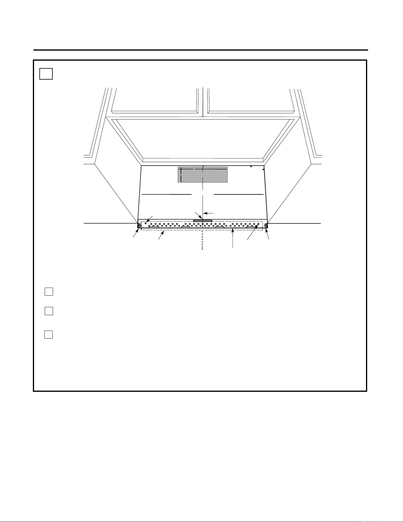
Installation Instructions
ALIGNING THE WALL PLATE
D.
CAUTION: Wear gloves
to avoid cutting fingers
on sharp edges.
Area E
Hole A
Hole B
Centerline
notches
Draw a Vertical Line
on Wall from Center
of Top Cabinet
Draw a Horizontal line on wall
from bottom of “Rear Wall
Template”.
Horizontal Line
Horizontal Line
C
L
3/8" TO EDGE
%#76+10Ä+(':*#756#ਸ਼+5
215+6+10'&
1765+&'
4'%1//'0&'&&+/'05+
10)4'#5'Ä.#&'0#+49+..
&+5%*#4)'+061*175'5647%674'
/+0+/7/9+&6*4'37+4'&
4'#49#..6'/2.#6'
NOTE: IT IS VERY IMPORTANT TO
READ AND FOLLOW THE DI
RECTIONS
IN THE INSTALLATION INSTRUCTIONS
BEFORE PROCEEDI
NG WITH
THIS
REAR WALL TEMPLATE.
This Rear Wal
l Template serves t
o position the bottom
mounting plate and to locate
the horizontal exhaust
outlet.
1. Use a level to check th
at the template is positioned
accurately.
2. Locate and ma
rk at least one stud on the left or
right side of the centerlin
e.
016'
It is important to use at least one wood
screw mounted firmly in a stud to s
upport the weight
of the microwave. Mark two add
itional, evenly spaced
locations for the supp
lied toggle bolts.
3. Drill holes in the marked locations. Where there is
a stud, drill a 3/16" hole for
wood screws. For hole
s
that do not line up with a st
ud, drill 5/8" holes for
toggle bolts.
016'
DO NOT INSTALL THE M
OUNTING PLATE
AT THIS TIME.
4. Remove the tem
plate from the rear wall.
5. Review the Installation Instru
ction book for your
installation situation.
Locate and mark
holes to align with h
oles in the
mounting plat
e.
IMPORTANT:
LOCATE
AT LEAST ONE
STUD ON EITHER SIDE OF
THE CENTERLINE.
MARK THE LOCATION FOR 2
ADDITIONAL, EVENLY
SPACED
TOGGLE BOLTS IN
THE MOUNTING PLATE
AREA.
Locate and mark
holes to align with hol
es in the
mounting plat
e.
IMPORTANT:
LOCATE
AT LEAST ONE
STUD ON EITHER SIDE OF
THE CENTERLINE.
MARK THE LOCATION FOR 2
ADDITIONAL, EVENLY
SPACED
TOGGLE BOLTS IN
THE MOUNTING PLATE
AREA.
Trim the rear
wall template al
ong the dotted
line.
%
#
$
%
&
(%76176(14*14+<106#.
1765+&'':*#756
%76*1.'6*417)*
4'#49#..
(14':*#756#ਸ਼
12"
4"
Darle vuelta a la hoja para consultar la
versión en Español.
NOTE: Holes A and B are inside area E. If both of
A and B are not in a stud, find a stud somewhere in
area E and draw a forth circle to line up with the
stud. It is important to use at least one wood
screw mounted firmly in a stud to support the
weight of the microwave. Set the mounting plate
aside.
1
3
2
Draw a Vertical line on the wall at the center of
the 30" wide space.
Draw a Horizontal line on the wall at the
bottom of "Rear Wall Template".
Drill 5/8" holes for toggle bolts on 2 locations
(Hole A, Hole B) but if the location of hole
is same as that of stud, drill a 3/16" hole for
wood screw. In other words, toggle bolt can
not be used to the location of stud.
NOTE: DO NOT MOUNT THE PLATE AT THIS
TIME.
8
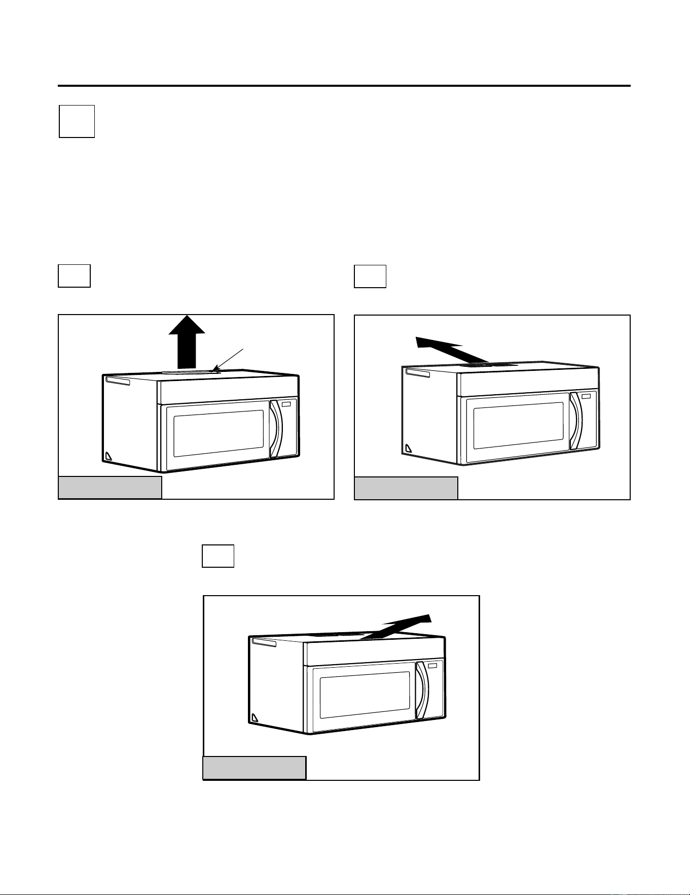
A
INSTALLATION TYPES
This microwave is designed for adaptation to the
following three types of ventilation:
A. Outside Top Exhaust (Vertical Duct)
B. Outside Back Exhaust (Horizontal Duct)
C. Recirculating (Non-Vented Ductless)
OUTSIDE TOP EXHAUST
(VERTICAL DUCT)
OUTSIDE BACK EXHAUST
(HORIZONTAL DUCT)
RECIRCULATING
(NON-VENTED DUCTLESS)
See page 12
On models shipped for
recirculating exhaust, a
disposable charcoal
filter is factory installed
to help remove smoke
and odors.
Adaptor in
Place for
Outside Top
Exhaust
Installation Instructions
2
B
C
Adaptor Must Be
Moved to the
Back for Outside
Back Exhaust
(Choose A, B or C)
NOTE: This microwave is shipped assembled for
Recirculating. Select the type of ventilation
required for your installation and proceed to
that section.
See page 16
See page 20
9
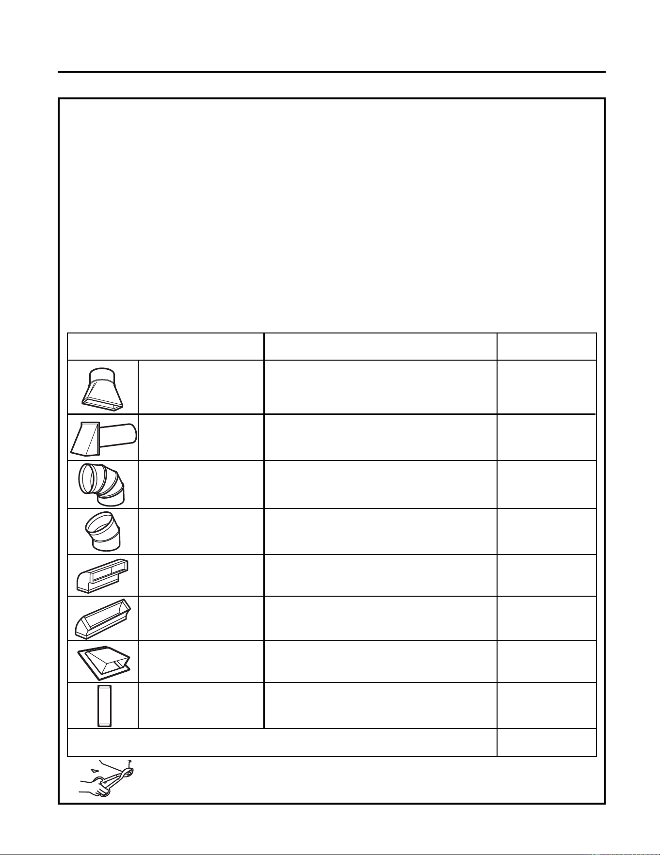
EQUIVALENT NUMBER EQUIVALENT
DUCT PIECES LENGTH x USED = LENGTH
5 Ft. (1.5 m) x ( ) = Ft. or m
Rectangular-to-
Round Transition
Adaptor*
Wall Cap 40 Ft. (12.2 m)x ( ) = Ft. or m
90° Elbow 10 Ft. (3 m) x ( ) = Ft. or m
45° Elbow 5 Ft. (1.5 m) x ( ) = Ft. or m
90° Elbow 25 Ft. (7.6 m) x ( ) = Ft. or m
45° Elbow 5 Ft. (1.5 m) x ( ) = Ft. or m
Roof Cap 24 Ft. (7.3 m) x ( ) = Ft. or m
1 Ft. (0.3 m) x ( ) = Ft. or m
Straight Duct 6" (15.2
cm) Round or 3
1
⁄4" x 10"
(8.2 x 25.4 cm)
Rectangular
Total Ductwork = Ft. or m
Equivalent lengths of duct pieces are based on actual
tests and reflect requirements for good venting
performance with any vent hood.
* IMPORTANT: If a rectangular-to-round transition
adaptor is used, the bottom corners of the
damper will have to be cut to fit, using the tin
snips, in order to allow free movement of the
damper
.
NOTE: If you need to install ducts, note that the
total duct length of 3
1
⁄4" x
10" (8.2 x 25.4 cm)
rectangular or
Maximum duct length:
For satisfactory air movement, the total duct length of
3
1
⁄4" x10" (8.2 x 25.4 cm) rectangular or
6 "(15.2 cm)
diameter round duct should
not exceed120 equivalent feet (36.5 m).
Elbows, transitions, wall and roof caps,
etc., present additional resistance to airflow and
are equivalent to a section of straight duct which is
longer than their actual physical size. When
calculating the total duct length, add the equivalent
lengths of all transitions and adaptors plus the
length of all straight duct sections. The chart below
shows you how to calculate total equivalent
ductwork length using the approximate feet of
equivalent length of some typical ducts.
Installation Instructions
INSTALLATION INSTRUCTIONS FOR EXTERNAL EXHAUST DUCTING
5" (10.5 cm)
diameter/
5" (10.5 cm)diameter/ 6" (15.2 cm)
diameter round duct should not exceed 120
equivalent feet (36.5 m).
Outside ventilation requires a EXTERNAL EXHAUST
DUCT.Read the following carefully.
NOTE: It is important that venting be installed using
the most direct route and with as few elbows as
possible. This ensures clear venting of exhaust and
helps prevent blockages. Also, make sure dampers
swing freely and nothing is blocking the ducts.
Exhaust connection:
The exhaust adaptor has been designed to mate with
a standard 3
1
⁄4" x
10" (8.2 x 25.4 cm) rectangular
duct.
If a round duct is required, a rectangular-to-round
transition adaptor must be used.
A 5
"
(10.5cm)/ 6
"
(15.2cm) diameter duct
is
.
acceptable to use
10
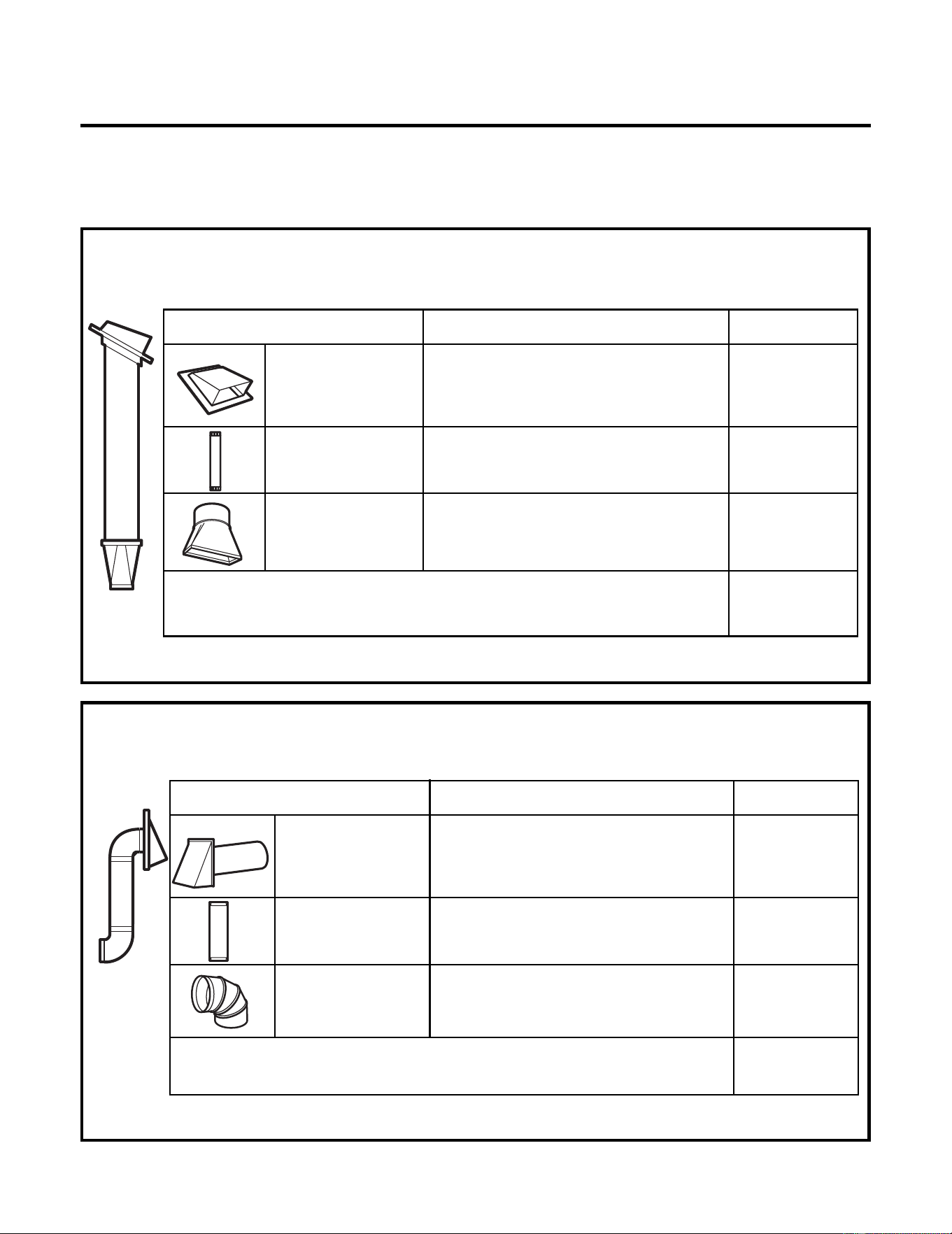
EQUIVALENT NUMBER EQUIVALENT
DUCT PIECES LENGTH x USED = LENGTH
Roof Cap 24 Ft. (7.3 m) x (1) = 24 Ft. (7.3 m)
12 Ft. (3.6 m) x (1) = 12 Ft. (3.6 m)
12 Ft. (3.6 m)
Straight Duct
(6”/15.2 cm Round)
5 Ft. (1.5 m) x (1) = 5 Ft. (1.5 m)
Rectangular-to-
Round Transition
Adaptor*
Equivalent lengths of duct pieces are based on actual
tests and reflect requirements for good venting
performance with any vent hood.
Total Length = 41 Ft. (12.5 m)
The following chart describes an example of one
possible ductwork installation.
NOTE: Read these next two pages only if you plan to vent your exhaust to the outside. If you
plan to recirculate the air back into the room, proceed to page 20.
OUTSIDE TOP EXHAUST (EXAMPLE ONLY)
NOTE: For back exhaust, care should be taken to align exhaust with space between studs, or wall should be
prepared at the time it is constructed by leaving enough space between the wall studs to accommodate
exhaust.
* IMPORTANT: If a rectangular-to-round transition adaptor is used, the bottom corners of the damper
will have to be cut to fit, using the tin snips, in order to allow free movement of the damper.
The following chart describes an example of one possible
ductwork installation.
Installation Instructions
OUTSIDE BACK EXHAUST (EXAMPLE ONLY)
EQUIVALENT NUMBER EQUIVALENT
DUCT PIECES LENGTH* x USED = LENGTH
Wall Cap 40 Ft. (12.2 m)x (1) = 40 Ft. (12.2 m)
3 Ft. (0.9 m) x (1) = 3 Ft. (0.9 m)
3 Ft. Straight Duct
(3
1
⁄4" x 10"/8.2 x 25.4
cm Rectangular)
90° Elbow 10 Ft. (3 m) x (2) = 20 Ft. (3 m)
Equivalent lengths of duct pieces are based on actual
tests and reflect requirements for good venting
performance with any vent hood.
Total Length = 63 Ft. (19.2 m)
EXTERNAL EXHAUST DUCTING
11
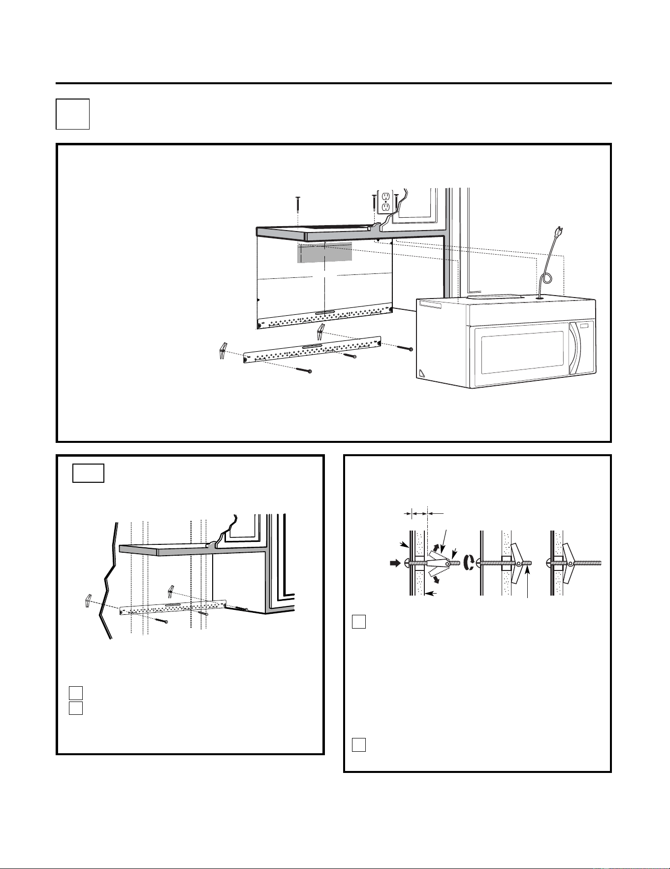
Place the mounting plate against the wall
and insert the toggle wings into the holes in
the wall to mount the plate.
NOTE: Before tightening toggle bolts and wood
screw, make sure the tabs on the mounting plate
touch the bottom of the cabinet when pushed
flush against the wall and that the plate is
properly centered under the cabinet.
CAUTION: Be careful to avoid pinching fingers
between the back of the mounting plate and the
wall.
Tighten all bolts. Pull the plate away from the
wall to help tighten the bolts.
3
4
ATTACH THE MOUNTING
PLATE TO THE WALL
A1.
Attach the plate to the wall using toggle
bolts. At least one wood screw must be
used to attach the plate to a wall stud.
Remove the toggle wings from the bolts.
Insert the bolts into the mounting plate
through the holes designated to go into
drywall and reattach the toggle wings to
3
⁄4 "(19 mm) onto
each bolt.
1
Wall
Mounting
Plate
Spacing for Toggles
More Than Wall
Thickness
Bolt End
Toggle
Bolt
Toggle Wings
To use toggle bolts:
Installation Instructions
2
OUTSIDE TOP EXHAUST (Vertical Duct)
A
•
Make sure the screws for
the blower motor and
blower plate are securely
tightened when they are
reinstalled. This will help to
prevent excessive vibration.
• Make sure the motor wiring has
been properly routed and
secured, and that the wires are
not pinched.
INSTALLATION OVERVIEW
A1. Attach Mounting Plate to Wall
A2. Prepare Top Cabinet
A3.
Adapting Microwave Blower for
Outside Top Exhaust
A4. Check Damper Operation
A5. Mount Microwave
A6. Adjust Exhaust Adaptor
A7. Connect Ductwork
IMPORTANT NOTES:
3/
8"
TO
EDG
E
%#
76
+
10
Ä
+(
':*#756
#&#
2614+5215+6
+10
'&1765+&'
4'%
1/
/'0
&'&
&+/'05+10)
4'#
5'Ä
.
#&'0#
+49+..
&
+5%
*#
4)'
+06
1*175'56
4
7%6
74'
/+0+/7/9+&6*
4'37+
4'&
4'#49#..6'/2.#6'
NO
TE:
IT IS VERY
I
MPORTANT TO
READ AND FO
LLOW
T
HE
D
IRECTIONS
IN THE INSTALLAT
ION INSTRU
CTI
ON
S
BE
FO
RE PR
O
CEEDINGWITH
TH
IS
R
EAR WALL TEM
PLATE.
T
hi
s R
e
a
rWa
l
l T
e
mpl
a
te se
rves
to p
o
s
itio
n th
e b
ottom
moun
ting
pla
te
and
to loc
a
te th
e hor
iz
on
ta
l e
xhau
st
ou
t
let.
1. Us
e a l
e
vel
t
o c
h
ec
k
th
a
t the
te
mpla
te i
s
po
sit
ioned
ac
cu
r
a
te
ly
.
2. L
oc
ate
andm
ark a
t lea
st o
nes
tud
on theleft
or
r
ight
s
ide of th
e c
en
terli
ne.
016'
It i
s imp
o
rta
n
t to u
se
at le
as
t one
wo
od
sc
re
w
m
ounted
fir
mly
i
n
a
s
tud
to supp
ort the w
eight
ofthe mic
ro
w
a
ve. M
a
rk tw
o
ad
diti
on
a
l, ev
en
ly
spa
c
ed
loc
atio
n
s
for the
su
ppl
ied to
g
gle bol
t
s.
3. Dr
i
ll h
ole
s in th
e m
arked loc
atio
ns
.
Where t
her
e is
a
s
tud
,
dril
l
a 3/1
6"
hole
for
woo
d sc
r
ew
s. F
o
r h
o
les
th
atdo
n
o
t lin
e up
w
ith
a
stud, d
r
ill
5
/8"
ho
le
s
fo
r
to
ggl
e bolts
.
016
'
DO NOT I
N
ST
AL
L THE MO
U
NTI
N
G
P
L
ATE
AT
T
HIST
IME.
4. Remov
e
th
e te
mpla
te fr
o
mthe r
ea
r
wal
l.
5.
Re
v
iewthe Ins
ta
ll
a
ti
onInst
r
uc
ti
o
n bo
ok
for
y
ou
r
in
stal
la
tion
situa
ti
on.
Locat
e and m
ark holes to align w
ith holes in t
he
mounting
plate.
IMP
ORTANT:
LO
C
A
T
E
AT LEAST O
NE STUD
O
N
EIT
HERSID
E O
F
THE CENT
E
RLIN
E
.
MARKT
HE LO
CATIONF
O
R 2 ADDIT
ION
A
L, EV
ENL
Y
SP
ACE
D T
O
GGLE BOLTS IN
THE MOUN
TING
PLATE
AREA.
Locate and mar
k
holes to ali
gn with holes in t
he
mountingplate.
IMPORTANT
:
LOC
A
T
E AT LEA
ST O
NE
STUD
O
N EI
THER SI
D
E O
F
TH
E CENT
E
R
LIN
E
.
MARKTHE LO
CATIO
NF
OR 2 ADDITIONA
L, EV
ENL
Y
SP
ACEDTOG
GLE BO
LTS IN
THE MOUN
TING PLATE
AREA
.
Trim the r
e
ar wall tem
plat
e along
the do
tted line.
Trim the rear
wall templa
t
e along
the dotted line.
%
(%76176(14*14+<106#.
1765+&'':*#756
%7
6
*1
.
'6
*4
17)*
4'#49
#.
.
(14
':*#
756
#&#
26
14
12"
4"
Da
rl
ev
u
e
lt
a
a
laho
j
a
par
a
c
o
nsu
l
ta
r
la
v
er
si
ón
e
n
Es
pa
ñol.
12
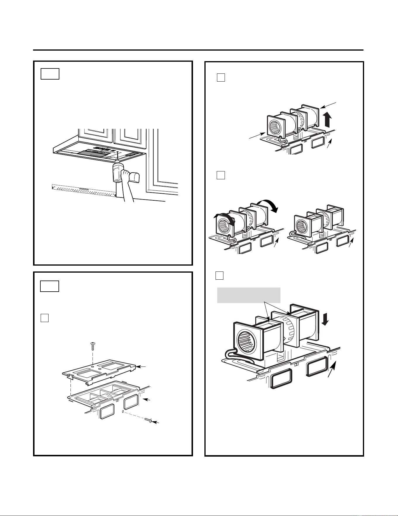
USE TOP CABINET TEMPLATE
FOR PREPARATION OF TOP
CABINET
You need to drill holes for the top support
screws, a hole large enough for the power cord
to fit through, and a cutout large
enough for the
exhaust adaptor.
A2.
• Read the instructions on the TOP CABINET
TEMPLATE.
• Tape it underneath the top cabinet.
• Drill the holes, following the instructions on
the TOP CABINET TEMPLATE.
CAUTION: Wear safety goggles when drilling
holes in the cabinet bottom.
Installation Instructions
A3.
Remove the screw that holds the blower plate
to the microwave. Remove and save the
screw holding the blower motor to the
microwave.
Blower Plate
Blower Motor
Screw
Back of
Microwave
2
End B
End A
Carefully pull out the blower unit. The
wires will extend far enough to allow you
to adjust the blower unit.
1
ADAPTING MICROWAVE
BLOWER FOR OUTSIDE
TOP EXHAUST
3
Back of
Microwave
Before Rotation After Rotation
Back of
Microwave
Back of
Microwave
Roll the blower unit 90° so that fan
blade openings are facing out the top
of the microwave.
Back of
Microwave
Place the blower unit back into the opening.
AFTER: Fan Blade
Openings Facing Top
CAUTION: Do not pull or stretch the
blower unit wiring. Make sure the wires
are not pinched, and that they are
properly secured.
4
Place the microwave in its upright
position, with the top of the unit facing
up.
13
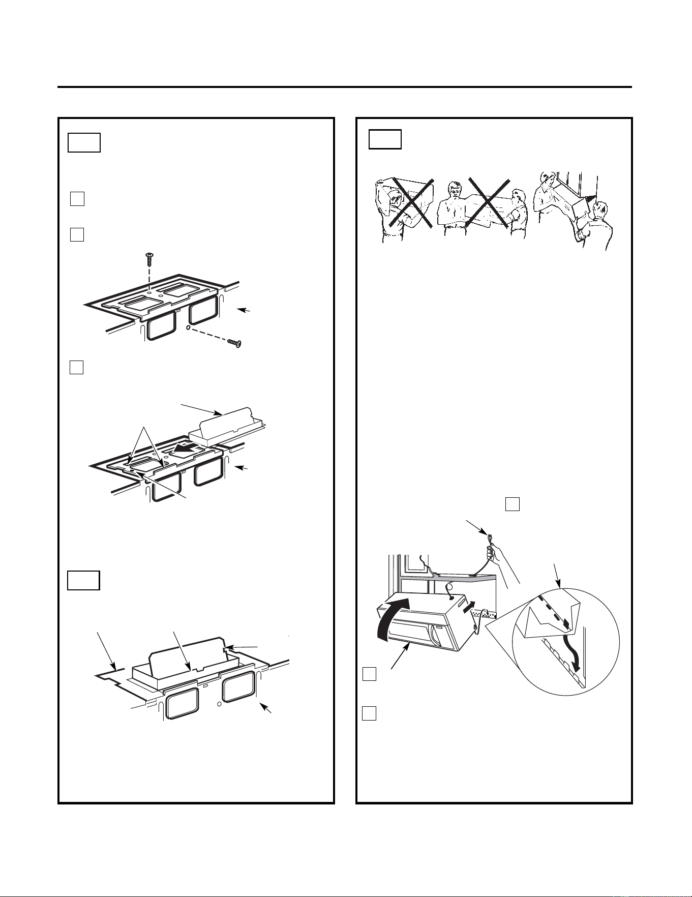
3
MOUNT THE
MICROWAVE
FOR EASIER INSTALLATION AND PERSONAL
SAFETY, WE RECOMMEND THAT TWO PEOPLE
INSTALL THIS MICROWAVE.
IMPORTANT: Do not grip or use handle
during installation.
NOTE: If your cabinet is metal, use the nylon
grommet around the power cord hole to prevent
cutting of the cord.
NOTE: We recommend using filler blocks if the
cabinet front hangs below the cabinet bottom
shelf.
IMPORTANT: If filler blocks are
not used, case damage may occur from
overtightening screws.
2
Rotate front of oven
up against cabinet
bottom.
Insert a self-aligning screw through top
center cabinet hole. Temporarily secure the
microwave by turning the screw at least two
full turns after the threads have engaged. (It
will be completely tightened later.) Be sure to
keep power cord tight. Be careful not to pinch
the cord, especially when mounting flush to
bottom
of
cabinet.
NOTE: When mounting
the microwave,
thread power cord
through hole in bottom of
top cabinet. Keep it tight
throughout Steps 1–3. Do
not pinch cord or lift oven
by pulling cord.
Lift microwave, tilt
it forward, and
hook slots at back
bottom edge onto
four lower tabs of
mounting plate.
1
CHECK FOR PROPER
DAMPER OPERATION
Exhaust Adaptor
Blower Plate
Damper
Back of
Microwave
• Make sure tape securing damper is removed
and damper pivots easily before mounting
microwave.
• You will need to make adjustments to assure
proper alignment with your house exhaust duct
after the microwave is installed.
A3.
ADAPTING MICROWAVE
BLOWER FOR OUTSIDE
TOP EXHAUST
5
Secure blower unit to microwave with the
screw removed in Step 1. Make sure the
screw is tight.
Replace blower plate with the screw
removed in Step 1. Make sure the screw
is tight.
Back of
Microwave
6
7
Back of
Microwave
Guide
Adaptor
Attach the exhaust adaptor to the top of
the blower plate by sliding it into the
guides
of the
blower plate.
Locking Tab
Push in securely until it is in the locking tabs.
Take care to assure that the damper
hinge
is
installed so that the
damper
swings freely.
A4.
A5.
Installation Instructions
14
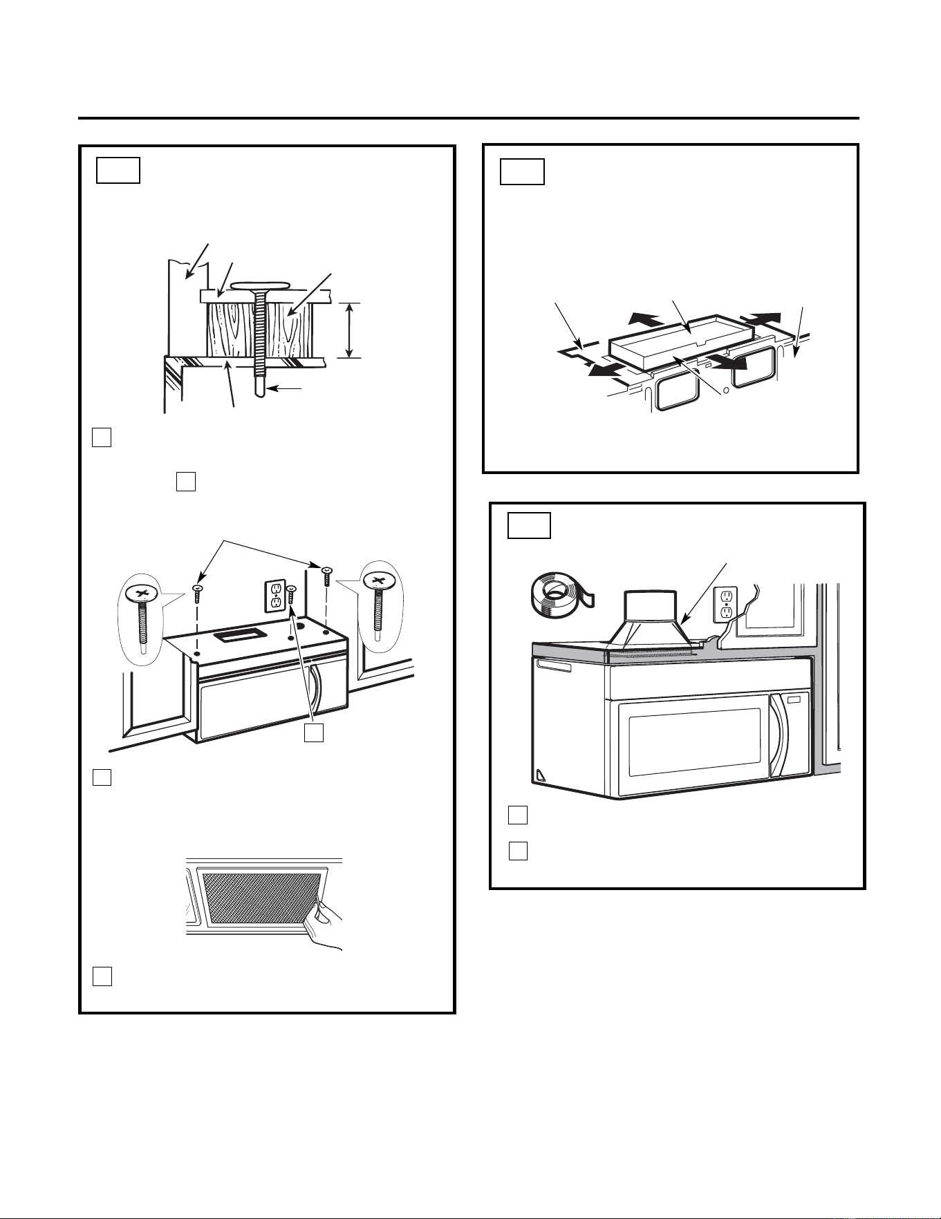
4
Attach the microwave to the top cabinet.
8
7
6
Cabinet Front
Cabinet Bottom Shelf
Tighten the outer two screws to the top of
the microwave. (While tightening
screws, hold the microwave in place
against the wall and the top cabinet.)
Filler Block
Equivalent
to Depth
of Cabinet
Insert 2 self-aligning
screws through outer top
cabinet holes. Turn two
full
turns on each screw.
Tighten center
screw completely.
Install grease filters. See the Owner’s
Manual packed with the microwave.
Installation Instructions
ADJUST THE EXHAUST
ADAPTOR
Open the top cabinet and adjust the exhaust
adaptor to connect to the house duct.
Back of
Microwave
For Front-to-Back
or Side-to-Side
Adjustment, Slide
the Exhaust Adaptor
as Needed
Blower Plate
Damper
Recess
Self-Aligning Screw
Microwave Top
5
MOUNT THE MICROWAVE
(cont.)
A6.
A5.
CONNECTING DUCTWORK
1
2
House Duct
A7.
Extend the house duct down to connect to
the exhaust adaptor.
Seal exhaust duct joints using
furnance
duct
tape for high temperature applications.
15
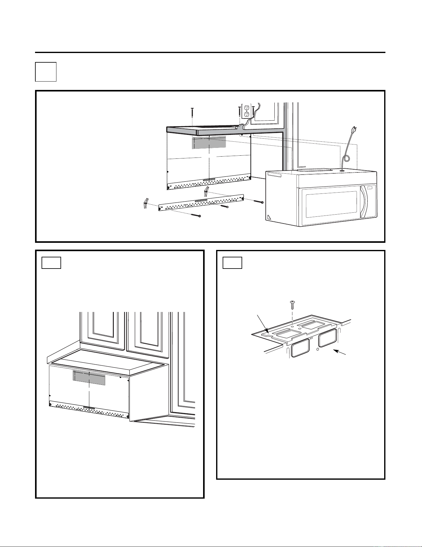
•
Make sure the screws for
the blower motor and
blower plate are securely
tightened when they are
reinstalled. This will
help to
prevent excessive vibration.
• Make sure the motor wiring has
been properly routed and
secured, and that the wires are
not pinched.
Remove and save the screw that holds the
blower plate to the microwave. Lift off the
blower plate.
Back of
Microwave
Installation Instructions
PREPARING THE REAR WALL
FOR OUTSIDE BACK
EXHAUST
B1.
You need to cut an opening in the rear wall
for outside exhaust.
• Read the instructions on the REAR
WALL TEMPLATE.
• Tape it to the rear wall, lining up with the
holes previously drilled for holes A and B
in the wall plate.
• Cut the opening, following the instructions of
the
REAR WALL TEMPLATE.
B2.
OUTSIDE BACK EXHAUST (Horizontal Duct)
B
Blower Plate
REMOVE BLOWER PLATE
INSTALLATION OVERVIEW
B1. Prepare Rear Wall
B2. Remove Blower Plate
B3. Attach Mounting Plate to Wall
B4. Prepare T
op Cabinet
B5. Adjust Blower
B6. Mount the Microwave
IMPORTANT NOTES:
3
/8
"
TO
EDG
E
%#
76
+10Ä
+
(
':*#756#
&#
26
14+5215+6
+1
0'&176
5+&'
4'%
1/
/'
0&'&
&
+/'05+10)4'#5'Ä.
#
&'0#+49+..
&
+5%*#4)'+06
1
*175
'564
7%6
74'
/
+0+/7/9+&6*4'37+4'&
4'#49#..6'/2.#6'
NOTE
: IT IS
VERY I
MPOR
TANT TO
READ AND FO
LLO
WT
HE
DIRECTION
S
IN THE INSTALLAT
ION INSTRU
CTI
ONS
BE
FO
RE PR
O
CEEDING
WITH T
HIS
REAR WA
LL TEM
PLA
T
E.
T
hi
s R
ea
r
Wa
ll Te
mpl
a
te
s
er
ve
s
to po
s
itio
n th
e b
otto
m
mou
ntin
g p
la
tea
n
d
to l
o
c
ate th
e h
o
r
i
z
on
ta
l ex
h
au
st
out
le
t.
1
. Use a
l
e
vel
to
c
h
ec
k
th
at th
e t
empla
te
is p
os
ition
ed
a
ccu
r
atel
y
.
2. L
o
c
a
te a
nd
m
ar
k a
t lea
s
t o
ne
stu
d
on
th
e
le
ft o
r
r
ight
s
id
e
o
f the cen
te
rline
.
016
'
It is im
po
rt
an
t to
u
se a
t le
ast
one
wood
scre
w
mo
u
nte
d
fi
rmly
i
n a
s
tud
to support th
e weight
of
th
e mic
r
o
w
ave
.
M
ar
k tw
o a
ddi
tion
al, e
venlyspa
ced
loc
atio
n
s f
or
th
e
s
upp
l
ied
to
ggle
bo
lts.
3. Dr
i
ll
h
ol
e
s in
th
e m
ar
ked lo
ca
tio
n
s.Whe
re t
h
e
re is
a
s
tu
d
, dr
ill
a 3/16" h
ol
e
fo
r
woo
d
scr
ew
s.
F
o
r h
ole
s
th
at
d
o n
ot lin
e up
w
ith a
s
tu
d, d
r
il
l 5/8" h
ole
s fo
r
t
ogg
l
e bo
lts.
016
'
DO
NO
T
IN
ST
A
L
L T
HE
MO
U
NTI
NG
PLA
T
E
AT
T
HIST
IME.
4. Re
m
o
ve t
he te
mpla
te fr
o
m
the
rea
r
wal
l.
5.
R
e
vie
wth
e In
sta
llation
Ins
t
ruc
ti
on b
o
o
k for
y
ou
r
in
stallatio
n
si
tu
at
ion.
Locat
e
and m
ar
k holes
to ali
gn wi
th holes in the
mountingp
late.
IMPO
RTANT:
LO
C
A
T
E
AT LEAST
ON
E STUD
ON EI
T
HER
SID
E
O
F
THE
CENTER
LIN
E
.
MARKT
HE LOCATION
FOR 2 ADDIT
ION
A
L, EVENLY
SPACE
D TO
G
GLE
BO
LTS
I
N THE
MO
UN
TING
PLATE
AREA.
Locate and mar
k
hol
es
to al
i
gn with holes
in the
mountingplate.
IMPO
RTANT:
LO
CA
TE AT LEA
ST ON
ES
TUD
ON
EI
THER SI
D
E O
F
THE
CENT
ERLIN
E.
MARK
T
HE LO
CATIONF
O
R 2 ADDITION
A
L, EVENL
Y
SPACEDTO
G
GLE BO
LTS IN
THE MO
UN
TING
PLATE
AREA.
Trim the rear wal
l temp
late
along
t
he do
tted
line.
Trim t
he
rear
wal
l t
em
pla
te along
th
e dotted line.
%
(%76176(14*14+<106#.
1765+&'':*#756
%7
6*
1
.'6
*4
17)*
4'#4
9#..
(
1
4':*#756
#
1
4
12"
4"
Dar
l
ev
u
elt
a
a
laho
j
a
pa
ra
c
o
nsu
l
tar
la
v
e
r
s
ióne
nEs
pa
ñol
.
3/
8" TO E
D
GE
%#76
+10
Ä+(
':*
#
756
#
&
#
2614
+5215+6
+10
'&
17
6
5+&
'
4'%1//
'0&
'&&
+/'05+1
0)4
'#5'Ä.#
&
'0
#+4
9+.
.
&
+5%
*
#
4)'
+0
61*
175
'
564
7
%6
7
4
'
/+0+/7/9+&6*4'37+4'&
4'#49#..6'/2.#6'
NOTE
: IT IS VE
RY IMPOR
T
ANT
TO
READ
A
ND FOLL
OW
TH
E
DIR
ECTIONS
IN THE IN
STA
L
LATIONINSTR
U
CTIO
NS
BEFO
RE PR
OCEED
ING
WITHTHI
S
REAR
W
ALL
TEMPLA
TE
.
This
Re
arWall
Tem
pl
a
t
e
serv
est
op
ositi
on
t
h
ebot
tom
m
ountingpla
te
a
nd
t
o
loc
a
t
ethe
h
oriz
o
ntal
exhaust
out
let.
1. Us
ea
levelt
o
checkt
hat
thetem
plat
e
isposi
tioned
accurat
ely.
2.
Loc
ateand mark a
t
lea
st
one
stud
on
the
l
ef
t
or
right side o
ft
h
ec
e
nt
er
line.
016
'
I
tis
im
port
ant
t
o
use
at
least
on
e
woo
d
scre
w
mount
e
d
firmly
ina
studto
s
upport
the
wei
ght
of
th
e
microwave.
Ma
rk
twoa
ddit
ional
,
e
v
enly
spaced
loca
tion
sforth
es
upplied
tog
g
lebolt
s.
3.
Drillh
olesin th
em
ark
ed
l
ocat
ions.Wh
eret
h
er
e
is
a st
ud,dri
lla 3
/
1
6"hole
fo
r
woodscrews.
Fo
r
hol
es
thatdo not
line
up
with
ast
u
d,
d
r
il
l5
/8"
hole
s
f
or
toggle
b
olts
.
01
6
'
DO
NO
T
IN
S
T
ALLT
HEM
OUNT
ING
P
LATE
ATTHI
S
T
IM
E.
4. Remov
e
thet
em
plat
e
from
the
rearwall.
5. R
eview
t
h
e
I
nstallat
io
n
I
n
s
truc
tionboo
kf
oryour
installationsit
ua
t
io
n.
Lo
cate and
mar
k hol
es to
a
lig
n with ho
l
es
in the
mou
nting plate.
IMP
O
RTANT:
LOCATE AT LEAST ONE
STUD
ON
EITH
ER SIDEOF
THE
C
ENTERLINE
.
M
AR
K TH
E LOCATION FOR
2 AD
D
ITI
O
NAL
,
EVENLY
SP
ACE
D TOGG
LE BOLTS IN
THE
MOUNTING
PLATE
AREA.
Lo
cate and mar
k hol
es to
a
lign w
ith ho
les
in the
mounting
p
late.
IMPORTA
NT:
LOCATEAT LE
AST ON
E STU
D O
N EITH
ER SIDE
OF
THE CE
N
TER
LINE.
MARK THE LOCAT
ION FOR
2 AD
DITI
ONAL
, EVENLY
SPAC
ED
TOGG
LE
BOLTS IN THE
MOU
NTI
N
G PLATE
AREA.
Trim
the
r
ear wall te
mplate a
l
on
g the dotted
line
.
Tri
m
ther
ea
r
wall
te
mpla
te
a
l
o
ng
the
d
otted
line
.
%
#$
%
&
(%76176(14*14+<106#.
1765+&'':*#756
%
7
6*
1.
'6*
4
17)*4
'#
4
9
#
.
.
(
14
':*#
7
56#
&#
261
4
1
2"
4"
Dar
levu
elta
a
la
hoja
pa
r
a
con
sultarla
ve
rsiónen
Españ
ol.
16
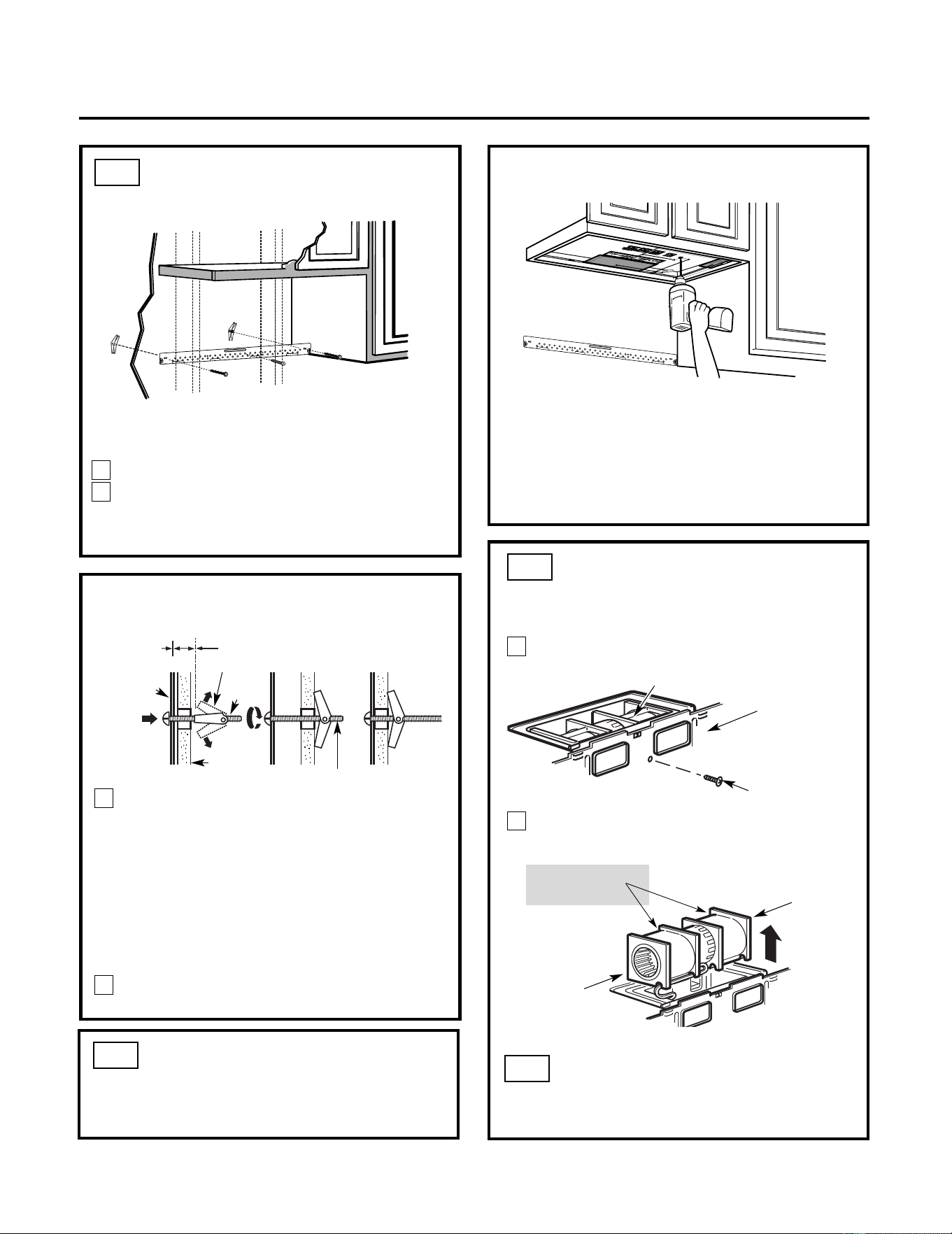
ATTACH THE MOUNTING
PLATE TO THE WALL
B3.
• Read the instructions on the TOP CABINET
TEMPLATE.
• Tape it underneath the top cabinet.
• Drill the holes, following the instructions on
the TOP CABINET TEMPLATE.
CAUTION: Wear safety goggles when drilling
holes in the cabinet bottom.
Wall
Mounting
Plate
Toggle
Bolt
Spacing for Toggles More
Than Wall Thickness
Toggle Wings
To use toggle bolts:
Bolt End
Installation Instructions
You need to drill holes for the top support screws
and a hole large enough for the power cord to fit
through.
Attach the plate to the wall using toggle bolts.
At least one wood screw must be used to
attach the p
late to a wall stud.
Remove the toggle wings from the bolts.
Insert the bolts into the mounting plate through
the holes designated to go into drywall and
reattach the toggle
wings to
3
⁄
4 "(19 mm) onto
each bolt.
1
2
P
lace the mounting plate against the wall
and
insert the toggle wings into the holes in
the wall to mount the plate.
NOTE: Before tightening toggle bolts and wood
screw, make sure the tabs on the mounting
plate touch the bottom of the cabinet when
pushed flush against the wall and that the plate
is properly centered under the cabinet.
CAUTION: Be careful to avoid pinching fingers
between the back of the mounting plate and the
wall.
Tighten all bolts. Pull the plate away from the
wall to help tighten the bolts.
3
4
2
1
Remove and save screw that holds blower
motor to microwave.
ADAPTING MICROWAVE
BLOWER FOR OUTSIDE
BACK EXHAUST
B5.
End B
End A
Back of
Microwave
Blower Motor
Blower Motor
Screw
Forward
Openings Facing
Carefully pull out the blower unit. The
wires will extend far enough to allow you
to adjust the blower unit.
Before: Fan Blade
USE TOP CABINET TEMPLATE
FOR PREPARATION OF TOP
CABINET
B4.
ADAPTING MICROWAVE
BLOWER FOR OUTSIDE
BACK EXHAUST (cont.)
B5.
17
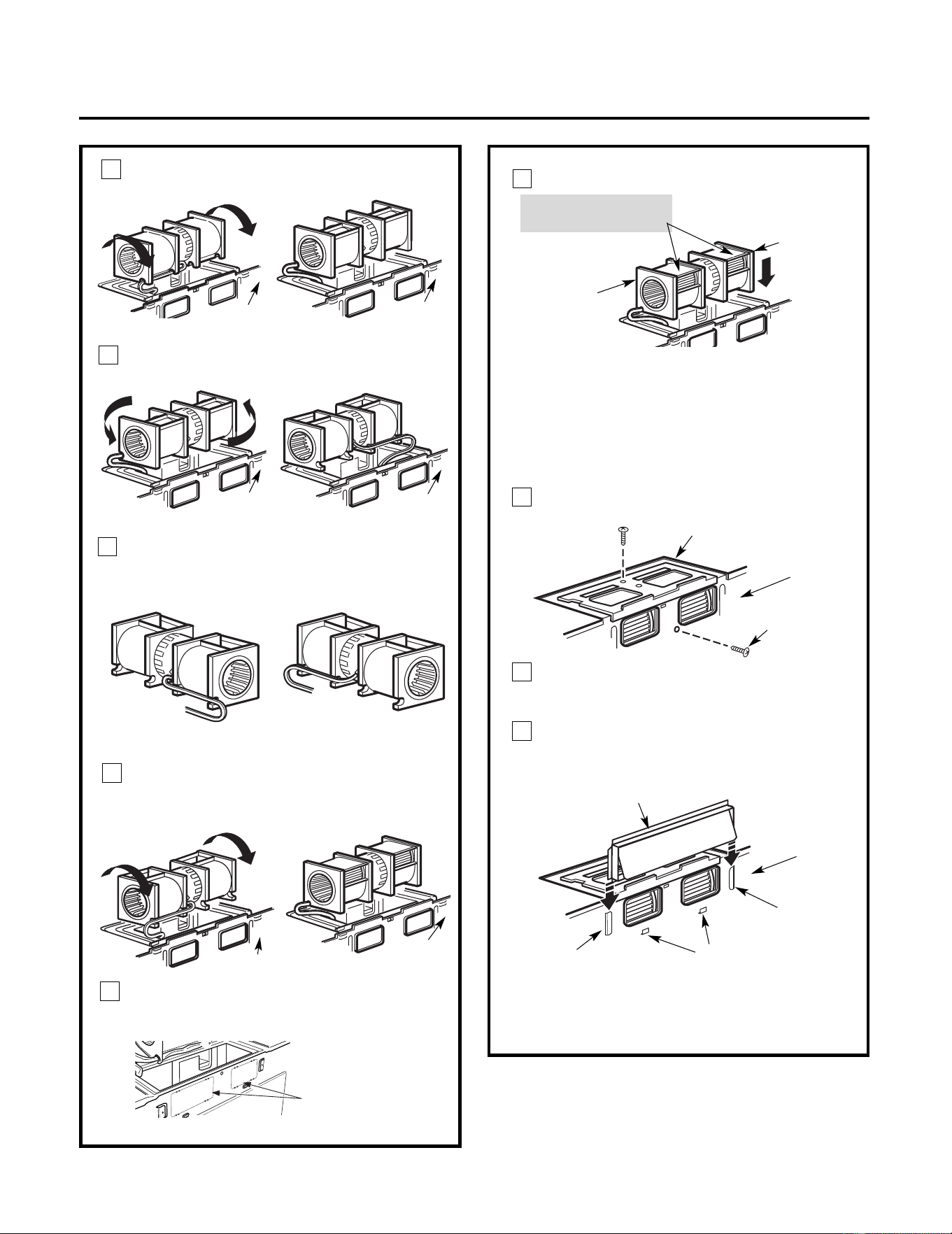
AFTER: Fan Blade
Openings Facing Back
Place the blower unit back into the opening.
Roll the blower unit 90° so that fan
blade openings are facing out the
back of the microwave.
Rotate blower unit counterclockwise 180°.
Before Rotation After Rotation
Gently remove the wires from the grooves.
Reroute the wires through grooves on other
side of the blower unit.
Before Rerouting After Rerouting
Wires Routed Through
Right Side
Wires Routed Through
Left Side
Back of
Microwave
Back of
Microwave
Blower Plate
Blower Motor
Screw
Before Rolling After Rolling
Back of
Microwave
End A
End B
Back of
Back of
Microwave
CAUTION: Do not pull or stretch the
blower unit wiring. Make sure the wires
are not pinched, and that they are
properly secured.
NOTE: The blower unit exhaust
openings should match exhaust
openings on rear of microwave
.
Secure the blower unit to the microwave
with the original screw.
Installation Instructions
Push in securely until it is in the lower
locking tabs. Take care to assure that the
damper hinge is installed so that it is at the
top and that the damper swings freely.
Guide
Guide
Adaptor
Locking Tabs
Back of
Microwave
Back of
Microwave
Roll the blower unit 90°
Back of
Microwave
3
4
5
6
11
Before Rotation After Rotation
7
Microwave
Remove the knockou t plates
in back of
the the unit with snips. (For
some models)
Back of mircrowave
Knockout Plates: Snip all
4 webs on each
knockout panel an d
remove the metal
knockouts for rear
airflow. Please take care
to remove any
sharp edges created
from removing the
knockout plates.
10
8
9
Replace the blower plate in the same
position as before with the screw. Make
sure the screw is tight.
Attach the exhaust adaptor to the rear of
the oven by sliding it into the guides at the
top center of the back of the microwave.
18
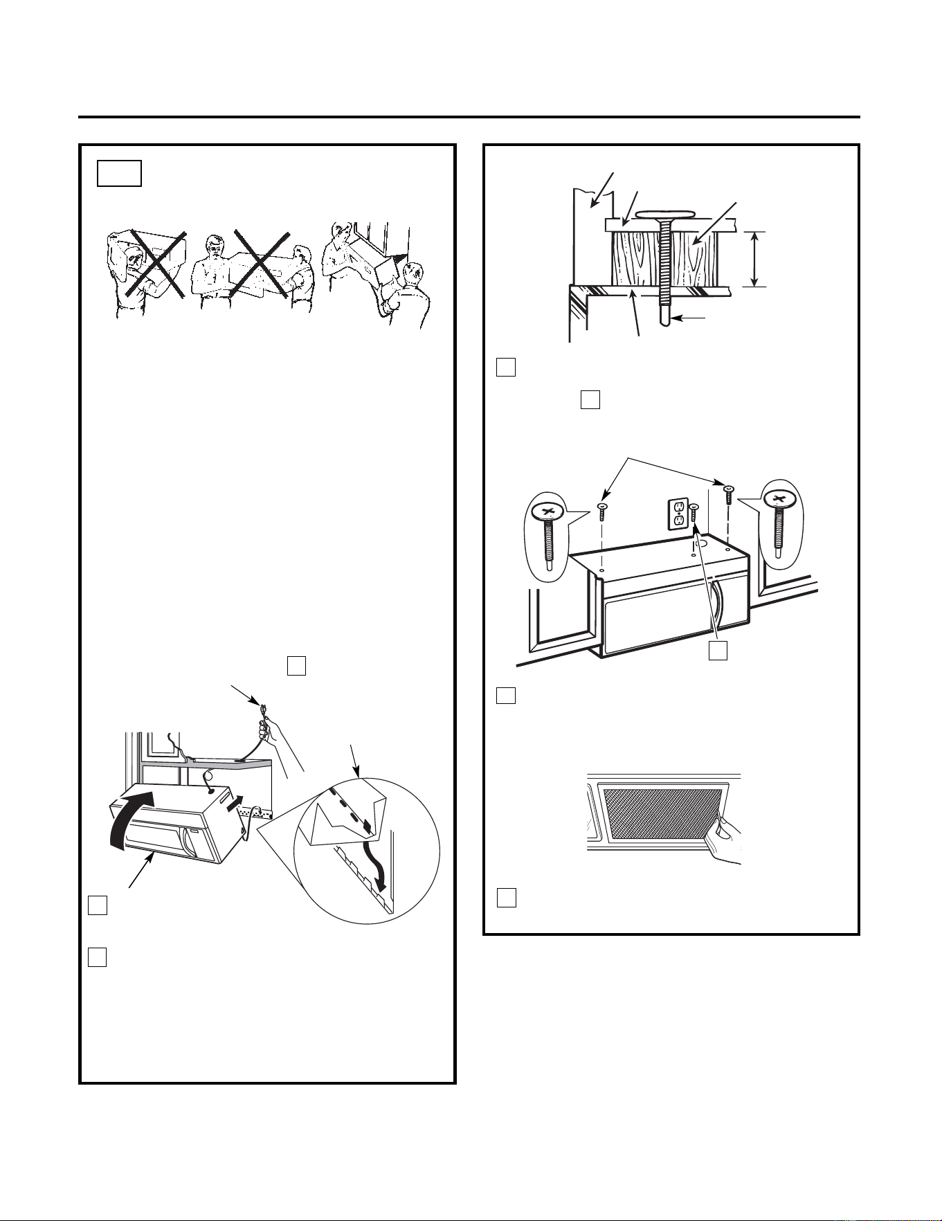
Installation Instructions
3
MOUNT THE MICROWAVE
OVEN
B6.
FOR EASIER INSTALLATION AND PERSONAL
SAFETY, WE RECOMMEND THAT TWO PEOPLE
INSTALL THIS MICROWAVE.
IMPORTANT: Do not grip or use handle
during installation.
NOTE: If your cabinet is metal, use the nylon
grommet around the power cord hole to
prevent cutting of the cord.
NOTE: We recommend using filler blocks if the
cabine
t front hangs below the cabinet bottom
shelf.
IMPORTANT: If filler blocks are not
used, case damage may occur from
overtightening screws.
8
7
5
Cabinet Front
Cabinet Bottom Shelf
Filler Block
Equivalent
to Depth
Insert 2 self-aligning
screws through outer top
cabinet holes. Turn two
full turns on each screw.
screw
completely.
Tighten the outer two screws to the top of
the microwave. (While tightening
screws, hold the microwave in place
against the wall and the top cabinet.)
Install grease filters. See the Owner’s
Manual packed with the microwave.
of Cabinet
Recess
Self-Aligning Screw
Microwave Top
Attach the microwave to the top cabinet.
6
Tighten center
4
2
Rotate front of the microwave
up against cabine
t
bottom.
Insert a self-aligning screw through top center
cabinet hole. Temporarily secure the microwave
by turning the screw at least two full turns after
the threads have engaged. (It will be completely
tightened later.) Be sure to keep power cord
tight. Be careful not to pinch the cord,
especially when mounting flush to bottom of
cabinet.
NOTE: When mounting
the microwave,
thread power cord
through hole in bottom of
top cabinet. Keep it tight
throughout Steps 1–3. Do
not pinch cord or lift oven
by pulling cord.
Lift microwave, tilt
it forward, and
hook slots at back
bottom edge onto
four lower tabs of
mounting plate.
1
19
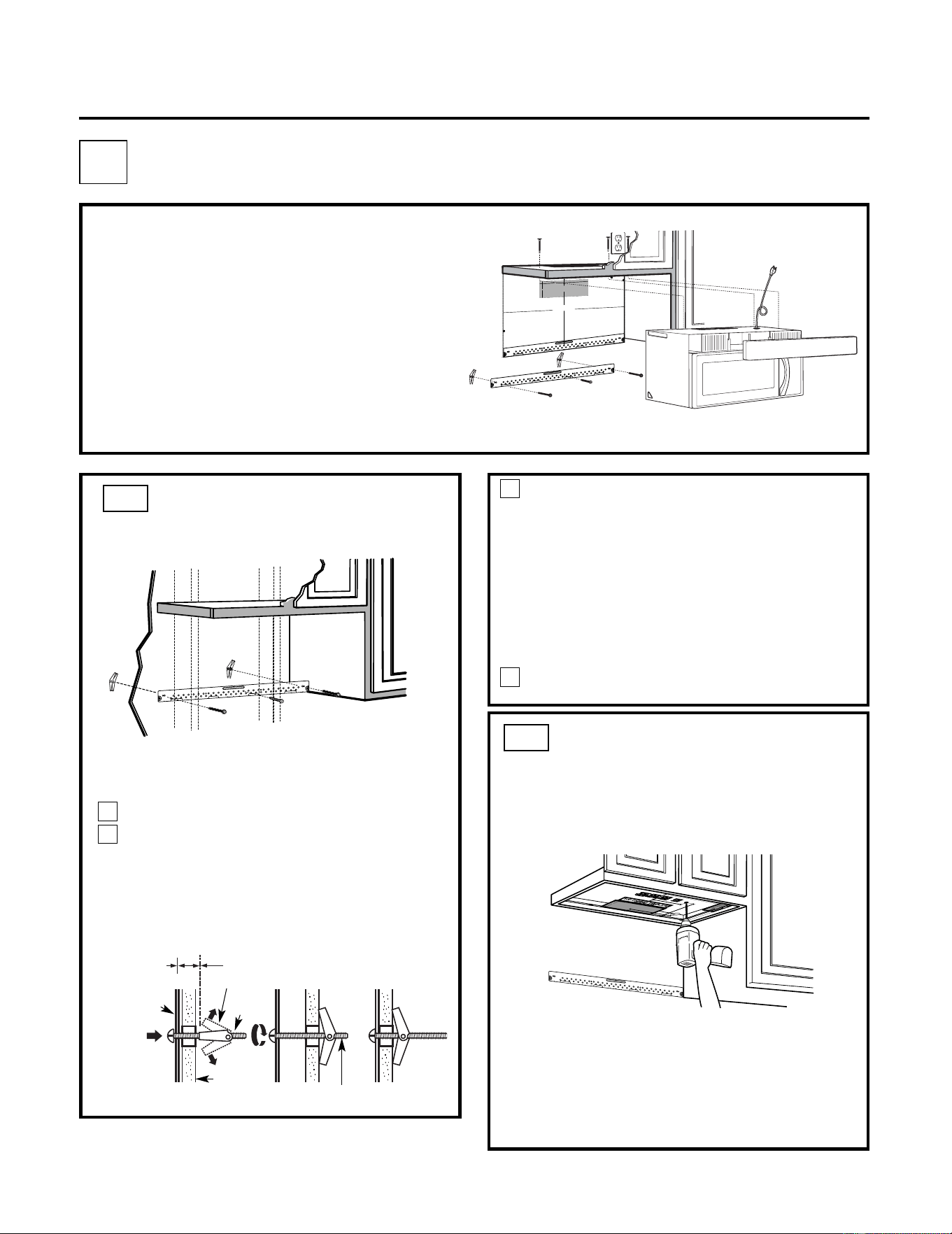
USE TOP CABINET TEMPLATE
FOR PR
EPARATION OF TOP
CABINET
C2.
C4.
C5.
IMPORTANT NOTES:
• Make sure the screws for th
e blower motor and
blower plat
e are securely tightened when they are
reinstalled. This will help to prevent excessive
vibration.
• Make sure the motor wiring has been properly routed
and secured, and that the wires are not pinched.
• Read the instructions on the TOP CABINET
TEMPLATE.
• Tape it underneath the top cabinet.
• Drill the holes, following the instructions on the
TOP CABINET TEMPLATE.
CAUTION: Wear safety goggles when drilling holes
in the cabinet bottom.
Installation Instructions
You need to drill holes for the top support screws
and a hole large enough for the power cord to fit
through.
Place the mounting plate against the wall
and insert the toggle wings into the holes in
the wall to mount the plate.
NOTE: Before tightening toggle bolts and wood
screw, make sure the tabs on the mounting plate
touch the bottom of the cabinet when pushed
flush against the wall and that the plate is properly
centered under the cabinet.
CAUTION: Be careful to avoid pinching fingers
between the back of the mounting plate and the
wall.
Tighten all bolts. Pull the plate away from the
wall to help tighten the bolts.
4
3
ATTACH THE MOUNTING
PLATE TO THE WALL
C1.
Attach the plate to the wall using toggle
bolts. At least one wood screw must be
used to attach the plate to a wall stud.
Remove the toggle wings from the bolts.
Insert the bolts into the mounting plate
through the holes designated to go into
drywall and reattach the toggle wings to
3
⁄4"(19 mm) onto each bolt.
1
Wall
Mounting
Plate
Spacing for Toggles
More Than Wall
Thickness
Bolt End
Toggle
Bolt
Toggle Wings
To use toggle bolts:
2
RECIRCULATING (Non-Vented Ductless)
C
Mount the Microwave
Install or change Charcoal Filter
INSTALLATION OVERVIEW
C1. Attach Mounting Plate to Wall
C2. Prepare Top Cabinet
C3. Check Blower Plate
3
/8
"T
O
E
D
G
E
%#76
+
1
0
Ä
+(
'
:
*
#
75
6
#
&
#
2
6
14
+5
2
1
5+6
+10
'
&
1
76
5
+
&'
4'%
1/
/'0
&
'
&
&
+/
'
0
5
+1
0
)
4'#
5'
Ä
.
#&
'
0#
+49
+.
.
&
+
5
%*#4)
'
+
06
1*
1
75
'
56
47
%6
7
4'
/+0+/7/9
+&6*4
'37+
4'&
4'#49#..6'/2.#6'
N
OTE:
ITIS VER
Y I
MP
OR
TAN
T
T
O
R
EAD
AN
D
F
O
LL
OW
T
HE
DI
RE
CTIO
NS
IN
T
H
E
INST
ALL
AT
IO
N
I
NS
TR
U
C
TI
O
N
S
B
EFO
R
E
PR
O
C
EE
DI
NG
W
IT
H
T
HIS
RE
AR
W
ALL
T
E
M
PL
A
T
E
.
Thi
s
Re
a
r
Wal
l
T
e
m
p
l
a
te
se
rve
s
t
o
p
o
s
i
t
ion
t
h
e
b
o
t
to
m
m
o
u
n
t
i
n
g
p
l
a
tea
n
d
t
o
l
o
c
a
t
e
t
h
e
h
o
r
iz
o
n
t
a
l
e
x
h
a
u
s
t
o
u
t
l
e
t
.
1
.
Use
a
l
e
v
e
l
t
o
c
he
c
k
t
h
a
t
t
h
e
t
e
m
p
la
t
e
i
s
p
o
sit
ion
e
d
a
c
c
u
r
a
te
l
y
.
2
.
L
o
c
a
te
a
n
d
ma
rk
a
t
l
e
a
s
t
o
n
e
s
t
u
d
o
n
th
e
l
e
f
t
o
r
r
ig
h
t
sid
e
o
f
th
e
c
e
n
te
rli
n
e
.
0
16
'
I
t
i
si
m
p
o
rt
a
nt
to
u
s
e
a
t
l
e
a
s
t
o
n
e
w
o
o
d
s
c
re
w
m
o
u
n
te
d
f
i
r
m
l
y
in
a
s
tu
d
t
o
s
u
p
p
o
rt
t
h
e
w
e
i
g
h
t
o
f
t
h
e
micro
w
a
v
e
.
Ma
rk
t
wo
ad
d
i
t
io
n
a
l,
e
v
en
l
y
s
p
a
c
e
d
l
o
c
at
ion
sfo
r th
e
s
u
p
p
l
i
e
d
t
o
g
g
le
bo
l
ts
.
3
.
Dr
i
ll
h
o
l
e
s
in
the
ma
r
k
e
d
l
o
ca
t
i
o
n
s
.
Whe
re
t
h
e
re
i
s
a
s
t
u
d
,
d
r
il
l
a
3
/16
"h
o
l
e
f
o
r w
o
o
d
sc
re
ws
.
F
o
r
h
o
l
e
s
th
a
t
d
o
n
o
t
l
in
e
u
p
wi
t
h
a
st
u
d
,
drill
5
/
8
"h
o
le
sf
o
r
t
o
g
g
l
e
b
o
lt
s
.
0
16
'
DO N
OT
IN
STA
L
L
TH
E
M
OU
N
TI
N
G
P
L
A
TE
A
T
T
H
IS
T
I
M
E
.
4
.
R
e
m
o
v
e
t
h
e
t
e
m
p
l
a
t
e
f
ro
m
t
h
e
re
a
r w
al
l
.
5
.
Re
v
ie
w
th
e
I
n
s
ta
l
l
a
t
i
o
n
In
s
t
ru
c
ti
on
b
o
o
k
f
o
ryo
u
r
i
n
s
t
a
lla
ti
o
n
s
i
tu
a
t
i
o
n
.
L
oc
ate
a
n
d
ma
r
k h
oles t
o
al
i
gn wit
h hol
es
in
th
e
mo
unt
i
n
g
p
l
ate.
I
MPO
RT
A
NT
:
L
OCA
T
E
A
T
LE
A
ST
ON
ESTU
D
O
N
EIT
HE
R
SI
D
E
O
F
T
HE
CE
NTE
RLIN
E.
MA
R
K
TH
EL
O
CA
T
I
O
N F
OR
2 AD
D
I
TI
ON
A
L, E
VEN
L
Y
SPA
CE
D
TO
G
GL
E
BOL
TS
IN
TH
EM
O
UN
T
I
N
G
P
LAT
E
A
REA
.
Lo
ca
te a
n
d
ma
rk
ho
les
t
o
a
l
i
gn
wi
t
h
ho
l
es
in
the
m
o
un
ting
p
la
te.
I
M
P
ORT
A
NT
:
L
O
C
A
T
E AT L
EAST
O
N
ES
T
UD
ON
E
IT
H
ER
SI
DE
O
F
T
HE
CE
NT
E
RL
IN
E.
M
ARK
T
H
EL
OC
A
TION F
OR2 A
DDI
T
I
ON
A
L,
EV
EN
L
Y
SP
A
C
E
D TOG
G
LE
BOL
T
S
IN
TH
E
MO
U
NT
ING
PLAT
E
A
RE
A.
T
rim th
e re
ar
w
all
t
e
mp
l
at
e
al
o
n
g
t
h
e d
o
t
t
ed
li
n
e.
Tri
m
th
e
rea
r
wa
ll
te
m
p
late
a
l
o
ng
t
h
e
d
o
t
ted
line
.
%
(%761
76(14*
14+<106#.
1765+&'':*#756
%
7
6
*1
.
'
6
*
4
17
)*
4
'
#
49
#.
.
(
1
4
'
:
*#
7
56
#
&#
2
6
1
4
1
2
"
4
"
D
a
r
le
vue
l
ta
a
la
ho
ja
para
cons
u
l
ta
rla
v
e
r
sió
n
e
n
Es
p
a
ño
l.
20
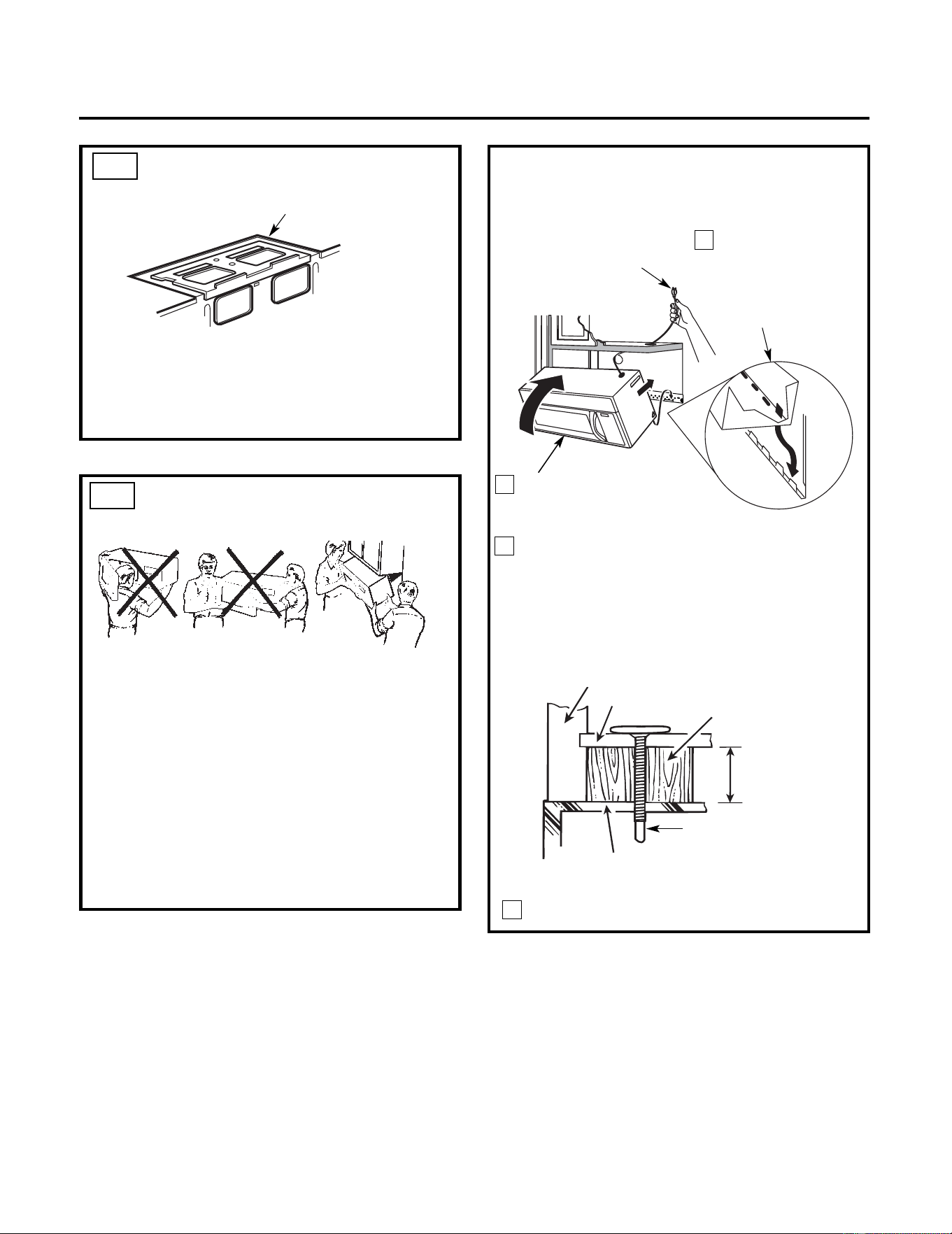
Attach the microwave to the top cabinet.
Cabinet Front
Cabinet Bottom Shelf
Filler Block
Equivalent to
Depth of
Cabinet Recess
Installation Instructions
3
MOUNT THE
MICROWAVE OVEN
FOR EASIER INSTALLATION AND PERSONAL
SAFETY, WE RECOMMEND THAT TWO PEOPLE
INSTALL THIS MICROWAVE.
IMPORTANT: Do not grip or use handle
during installation.
NOTE: If your cabinet is metal, use the nylon
grommet around the power cord hole to prevent
cutting of the cord.
NOTE: We recommend using filler blocks if the
cabinet front hangs below the cabinet bottom
shelf.
IMPORTANT: If filler blocks are not used,
case damage may occur from
overtightening screws.
Self-Aligning Screw
Microwave Top
4
2
Rotate front of oven
up against cabinet
bottom.
Insert a self-aligning screw through top
center cabinet hole. Temporarily secure the
oven by turning the screw at least two full
turns after the threads have engaged. (It will
be completely tightened later.) Be sure to
keep power cord tight. Be careful not to
pinch the cord, especially when mounting
flush to bottom of cabinet.
NOTE: When mounting
the microwave,
thread power cord
through hole in bottom of
top cabinet. Keep it tight
throughout Steps 1–3. Do
not pinch cord or lift oven
by pulling cord.
Lift microwave, tilt
it forward, and
hook slots at back
bottom edge onto
four lower tabs of
mounting plate.
1
C3.
C4.
CHECK BLOWER PLATE
• Place the microwave in its upright position, with
the top of the unit facing up.
• Check to see that the blower plate is correctly
installed on the unit.
Blower Plate
21
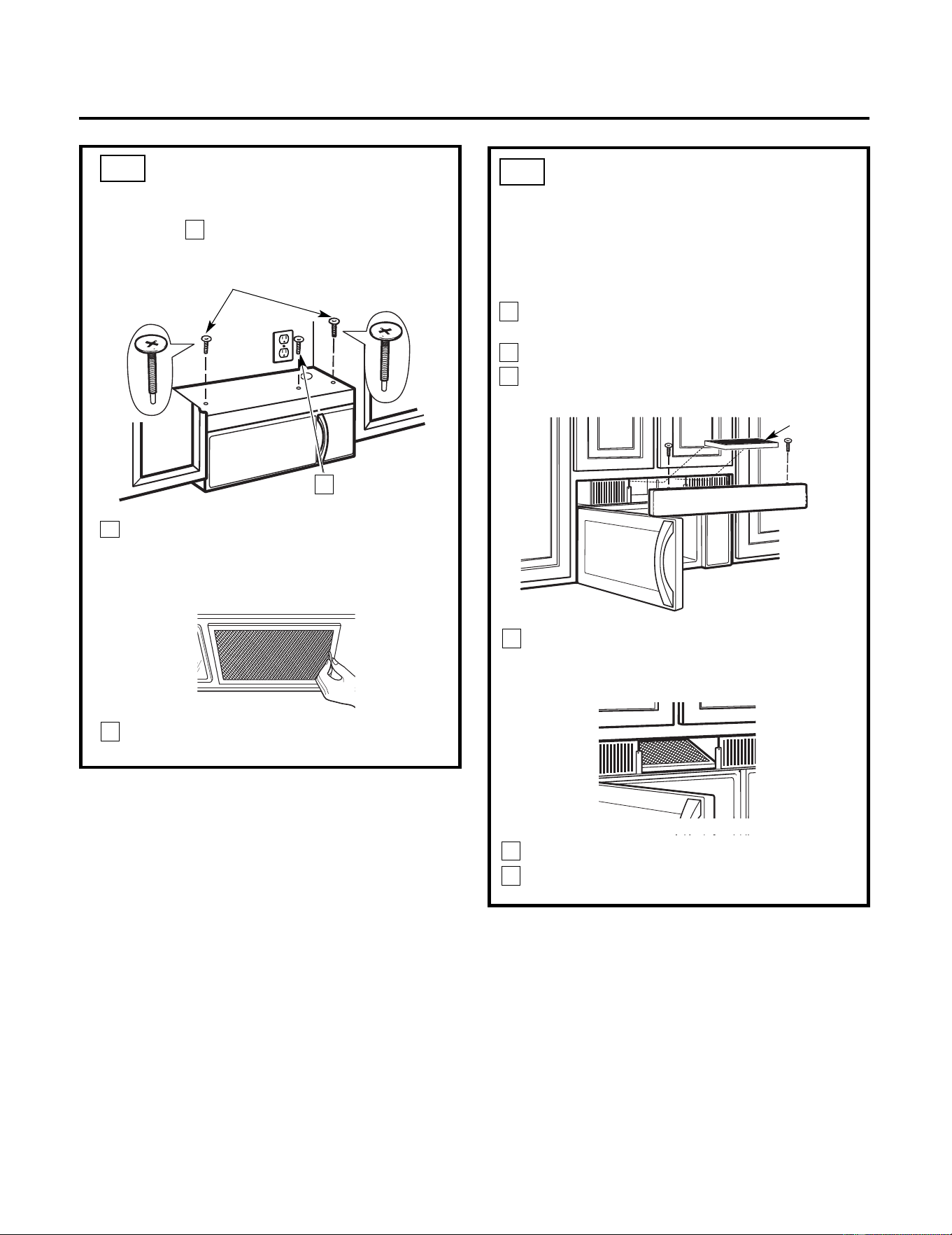
5
MOUNT THE MICROWAVE
(cont.)
Installation Instructions
8
7
6
Tighten the outer two screws to the top of
the microwave. (While tightening
screws, hold the microwave in place
against the wall and the top cabinet.)
Insert 2 self-aligning
screws through outer top
cabinet holes. Turn two
full turns on each screw.
Tighten center
screw
completely.
Install grease filters. See the Owner’s
Manual packed with the microwave.
Replace the grille and the screws.
Close the door.
C4.
3
2
1
Charcoal
Filter
NOTE: The charcoal filter is factory installed in
recirculating models. Follow these steps to replace a
filter or to install a filter after converting a vented
model to recirculating operation.
Remove screws on top of grille
using a #1 Phillips screwdriver.
Open the door.
Remove the grille.
Pull the grille straight off.
C5.
INSTALLING OR CHANGE
THE CHARCOAL FILTER
Install the charcoal filter: Insert filter upper
in the unit and then pull down filter. When
properly installed, the wire mesh of the filter
should be visible from the front.
Insert
22
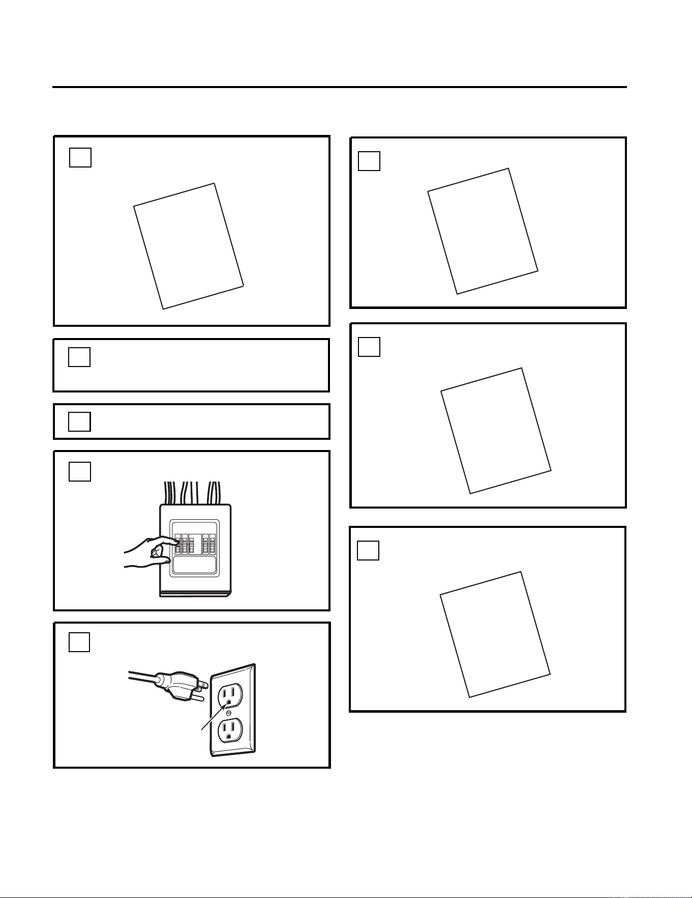
KEEP INSTALLATION IN
STRUCTIONS
FOR
THE LOCAL INSPECTOR’S USE.
Plug power cord into a dedicated 15- to
20-amp electrical outlet.
7.
6.
Replace house fuse or turn breaker back on.
4.
Remove all packing material from
the microwave.
2.
Make sure the microwave has been
installed according to instructions.
1.
BEFORE YOU USE YOUR MICROWAVE
Ensure proper
ground exists
before use
3.
5.
M
USE
ANUAL
CARE
&
FILL OUT PRODUCT REGISTRATION CARD
8.
GARD
Read the
Manual.
Installation Instructions
.
Install turntable ring and glass tray in cavity
PRODUCT
REGISTRATION
USE
&
CARE
INSTALLATION
INSTRUCTIONS
INSTALLATION
INSTRUCTIONS
23
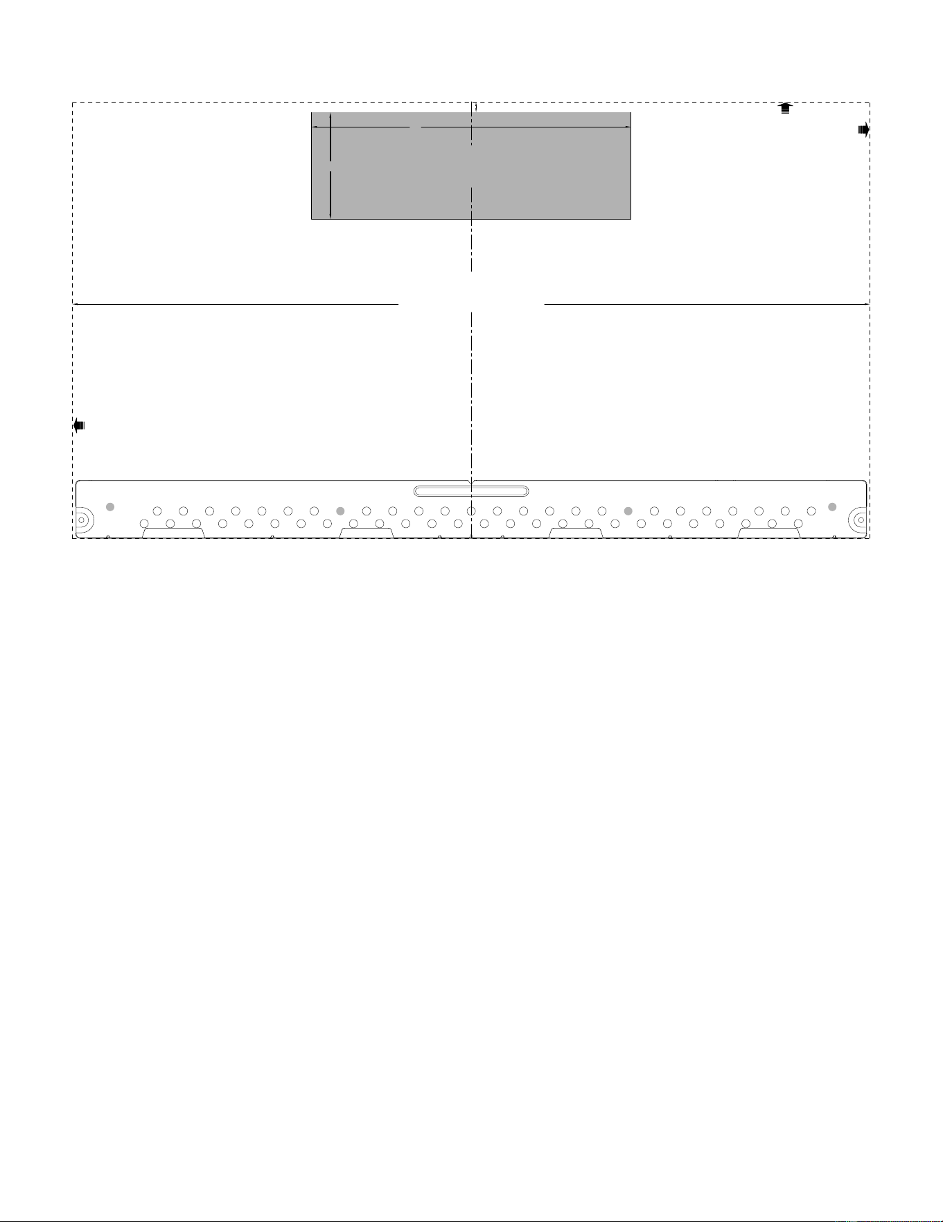
24
3/8" TO EDGE
%#76+10Ä+(':*#756#ਸ਼+5215+6+10'&1765+&'
4'%1//'0&'&&+/'05+10)4'#5'Ä.#&'0#+49+..
&+5%*#4)'+061*175'5647%674'
/+0+/7/9+&6*4'37+4'&
4'#49#..6'/2.#6'
NOTE: IT IS VERY IMPORTANT TO
READ AND FOLLOW THE DIRECTIONS
IN THE INSTALLATION INSTRUCTIONS
BEFORE PROCEEDING WITH THIS
REAR WALL TEMPLATE.
This Rear Wall Template serves to position the bottom
mounting plate and to locate the horizontal exhaust
outlet.
1. Use a level to check that the template is positioned
accurately.
2. Locate and mark at least one stud on the left or
right side of the centerline.
016'It is important to use at least one wood
screw mounted firmly in a stud to support the weight
of the microwave. Mark two additional, evenly spaced
locations for the supplied toggle bolts.
3. Drill holes in the marked locations. Where there is
a stud, drill a 3/16" hole for wood screws. For holes
that do not line up with a stud, drill 5/8" holes for
toggle bolts.
016'DO NOT INSTALL THE MOUNTING PLATE
AT THIS TIME.
4. Remove the template from the rear wall.
5. Review the Installation Instruction book for your
installation situation.
Locate and mark holes to align with holes in the
mounting plate.
IMPORTANT:
LOCATE AT LEAST ONE STUD ON EITHER SIDE OF
THE CENTERLINE.
MARK THE LOCATION FOR 2 ADDITIONAL, EVENLY
SPACED TOGGLE BOLTS IN THE MOUNTING PLATE
AREA.
Locate and mark holes to align with holes in the
mounting plate.
IMPORTANT:
LOCATE AT LEAST ONE STUD ON EITHER SIDE OF
THE CENTERLINE.
MARK THE LOCATION FOR 2 ADDITIONAL, EVENLY
SPACED TOGGLE BOLTS IN THE MOUNTING PLATE
AREA.
Trim the rear wall template along the dotted line.
Trim the rear wall template along the dotted line.
%
#$
%
&
(%76176(14*14+<106#.
1765+&'':*#756
%76*1.'6*417)*4'#49#..(14':*#756#ਸ਼
12"
4"
Darle vuelta a la hoja para consultar la
versión en Español.
