ISLAND
USER MANUAL
COOKER HOOD
eiQCURVISL90SS
eiQCURVISL90BL
1
CONTENTS
SAFETY PRECAUTIONS 2
INTRODUCTION 4
DIMENSIONS 4
UNPACKING YOUR APPLIANCE 4
PRODUCT OVERVIEW – PARTS SUPPLIED 5
OPTIONS FOR VENTILATION 6
7
9
OPERATION 12
MAINTENANCE 13
TROUBLESHOOTING 15
MANUFACTURER SUPPORT 15
15
SPECIFICATION 16
2
SAFETY PRECAUTIONS
Whilst this product complies with all safety requirements, incorrect
or inappropriate use can lead to personal injury and potential
damage to property. Please read the contents of this instruction
booklet or using this cooker hood.
· The cooker hood must be installed in accordance with the
installation instructions provided, making sure all measurements
and guidance are followed.
· All installation work must be carried out electrician
or a competent person.
· If venting externally, make sure the ducting has no bends sharper
than 90 degrees as this will
of the cooker hood.
· The cooker hood is for domestic use only and is not designed for
commercial use. It should only be us ed for the purpose it was
intended – to extract vapours and cooking odours.
· Do use an cooker hood.
· Do not try to use the cooker hood without the supplied grease
, or if excessively greasy. The filters should be
cleaned regularly following the guidance provided , and replaced
if necessary.
· Clean your appliance regularly, by following the method provided
in this manual. Failing to maintain the unit would increase the risk
.
· Do not dischar ge the air into
fumes from other appliances burning gas or other fuels.
· Do not leave frying pans unattended during use because
overheated fat or oils might catch .
· If the cooker hood is damaged, do not attempt to use it
.
3
· If the supply cord is
damaged
,
it must be replaced by the
manufacturer, its service agent, or
in
order to avoid an accident.
· cooker hood should not be used by people
(including children) with reduced physical
,
sensory
,
or mental
capabilities, or by those who lack experience and knowledge ,
unless they have been given supervision and instruction on how
to use the appliance by a person responsible for their safety.
· Accessible parts may become hot whe
n
used with cooking
appliances.
· This cooker hood is not a toy and children should be supervised
to ensure they do not play with it.
· The plug must be accessible after installation in case you need to
isolate it in an emergency. If the unit is hardwired to the mains via
a spur, a fused switch should be installed and accessible for it.
· The minimum distance between the hob surface and the lowest
part of the hood should be at least 65cm.
70cm and 80cm gives peak .
· The room MUST be adequately ventilated when the hood is in
use.
· Regulations concerning the discharge of air have to .
· If used in recirculation mode, the charcoal and
must be replaced
at
least
once a year
depending on how
frequen
tly the cooker hood has been used.
CAUTION: Accessible parts of the hood can become very hot
during use with cooking appliances, even when not in use, due
to heat rising from the hob . Sufficient cooling time should be
allowed before touching either the housing or the grease filters.
4
INTRODUCTION
Thank you for choosing an electriQ cooker hood.
This instruction manual is designed to provide you with all required
instructions related to the installation, use and maintenance of the appliance.
In order to operate the unit correctly and safely, please read this instruction
manual carefully before installation and usage.
YOUR APPLIANCE
• Please take great care when unpacking; a sharp blade should not be used
to open the box, as it may go deep enough inside to damage components.
Components damaged or marked by careless unpacking are not covered
under the guarantee.
• Carefully unpack the contents and check against the next section (Product
overview – parts supplied)
• Packaging materials should be recycled in accordance with local
regulations
DIMENSIONS OF THE HOOD
5
PRODUCT OVERVIEW - SUPPLIED
Description Illustration
Qty.
Cooker hood
1
Chimney
2
Adaptor
1
Cable Tie
1
Wall Bracket
1
Hanging hook
1
Metal angle bar
8
Screw (ST4) (4mm x
30mm)
Wall plug
Expansion bolt
(6mm x 50mm)
6
Screw (M5) (5mm x
10mm)
40
Screw (self-tapping)
(4mm x 6mm)
4
Nut
16
Metal washer
16
Air Flaps
2
6
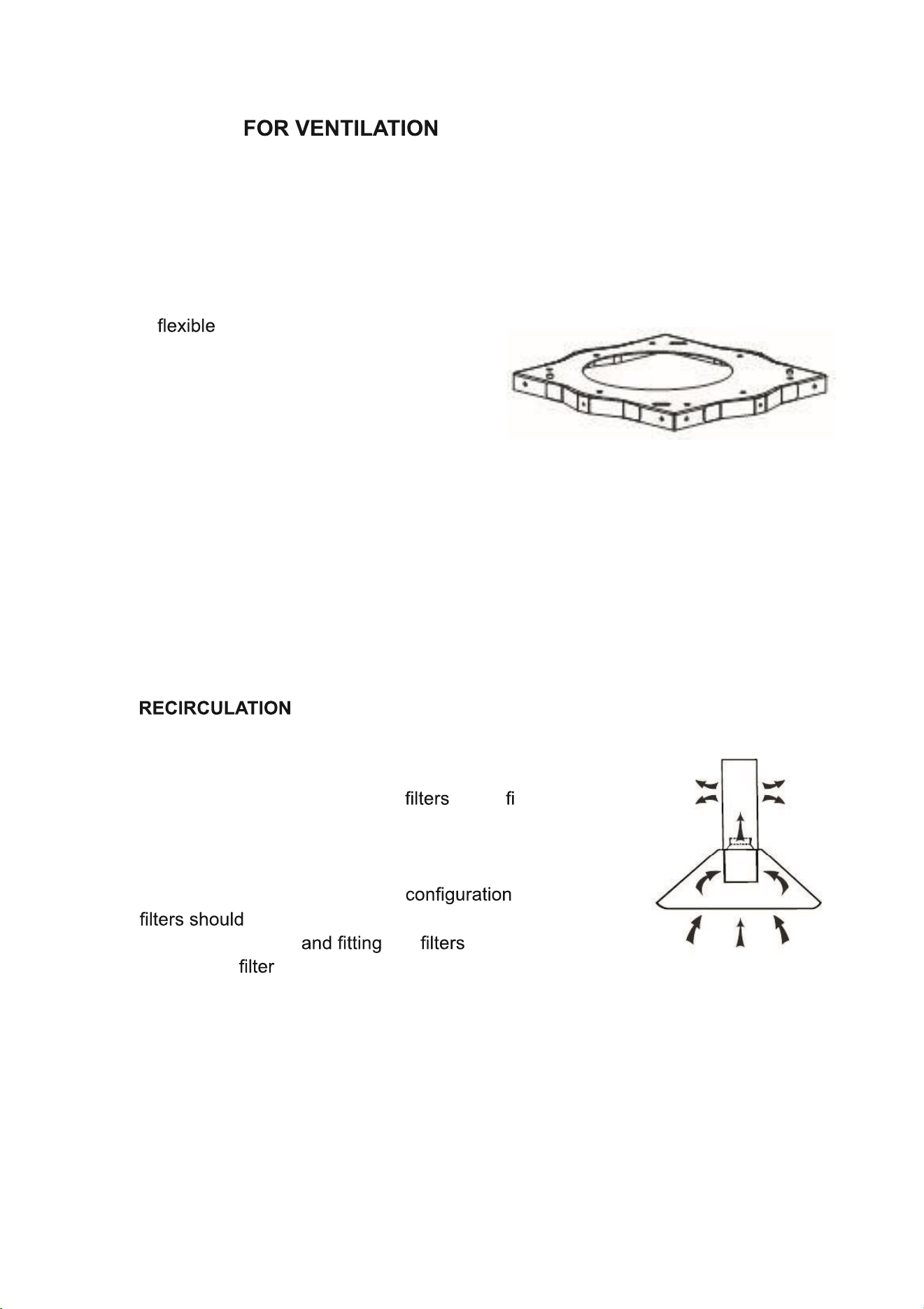
OPTIONS
This hood supports both external venting or recirculation. The type of setup
should be decided before commencing installation.
EXTERNAL VENTING
A pipe is provided which allows
the cooking odours to be extracted
outside. If this is the chosen installation
method consideration to the route of the
vent pipe should be made. The mounting
plate contains a hole allowing the vent
pipe to be connected and routed through the
ceiling.
If a vent pipe is to run through the ceiling a hole with a diameter of around
170mm should be made in the ceiling before installation. This would allow the
vent pipe to run through the mounting plate.
This cooker hood also supports the recirculation of air
once it has passed through the . The ltered air is
then expelled through the vent holes in the side of the
chimney.
When setting the unit up in this , carbon
also be used to remove odours from the air.
Details of sourcing the can be found in
the Carbon section.
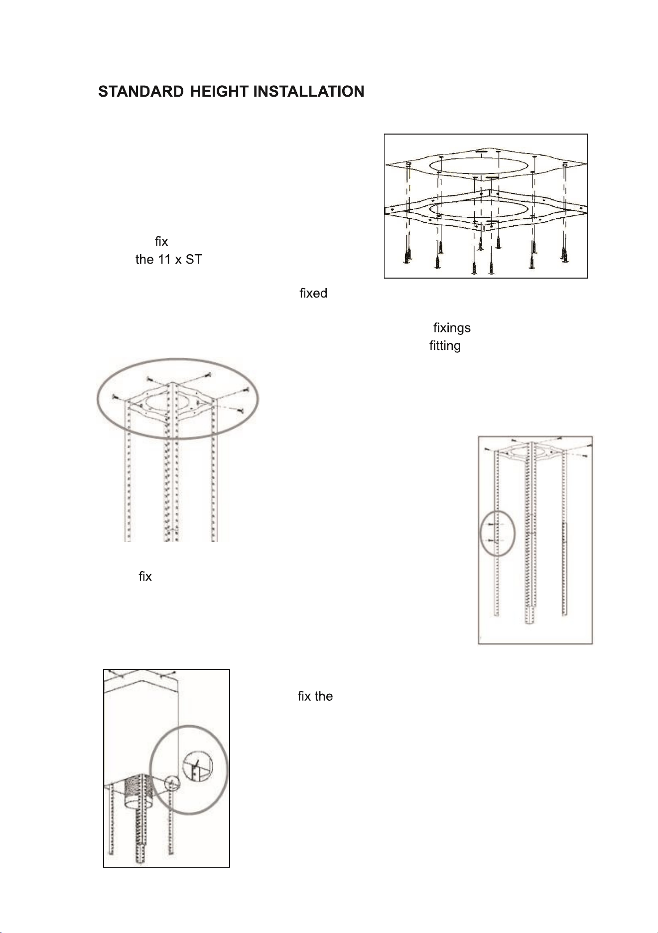
7
Do not connect the hood to the mains supply before installing it .
1. Position the hanging plate on the ceiling
and then mark the position of the screw
holes with a pencil.
Securely the hanging plate to the ceiling,
using (30 mm) screws.
Please ensure that the bracket is in a way it would support the weight of
the hood.
Depending on the construction of the ceiling, alternative may be
required. 6 x expansion bolts are also provided to allow to concrete.
2. Fix the angle bars to the hanging plate, using
the 8 x M5 screws.
3. Extend the angle bars to the required height and then
them in position using the 16 x M5 screws. The
angle bars must have an overlap of at least 100mm.
4. At this point, if the unit is to be externally vented
connect the ducting hose to the hanging plate.
Then upper chimney section to the hanging
plate, using the 4 x self-tapping screws (4mm x
6mm).
Slide the lower chimney section onto the angle bars
and raise it until it sits just below the upper chimney
section.
Use the hanging hook to temporarily keep the lower
chimney section in this position, to make sure that it
4
8
does not drop down whilst the main body of the hood to the angle bars.
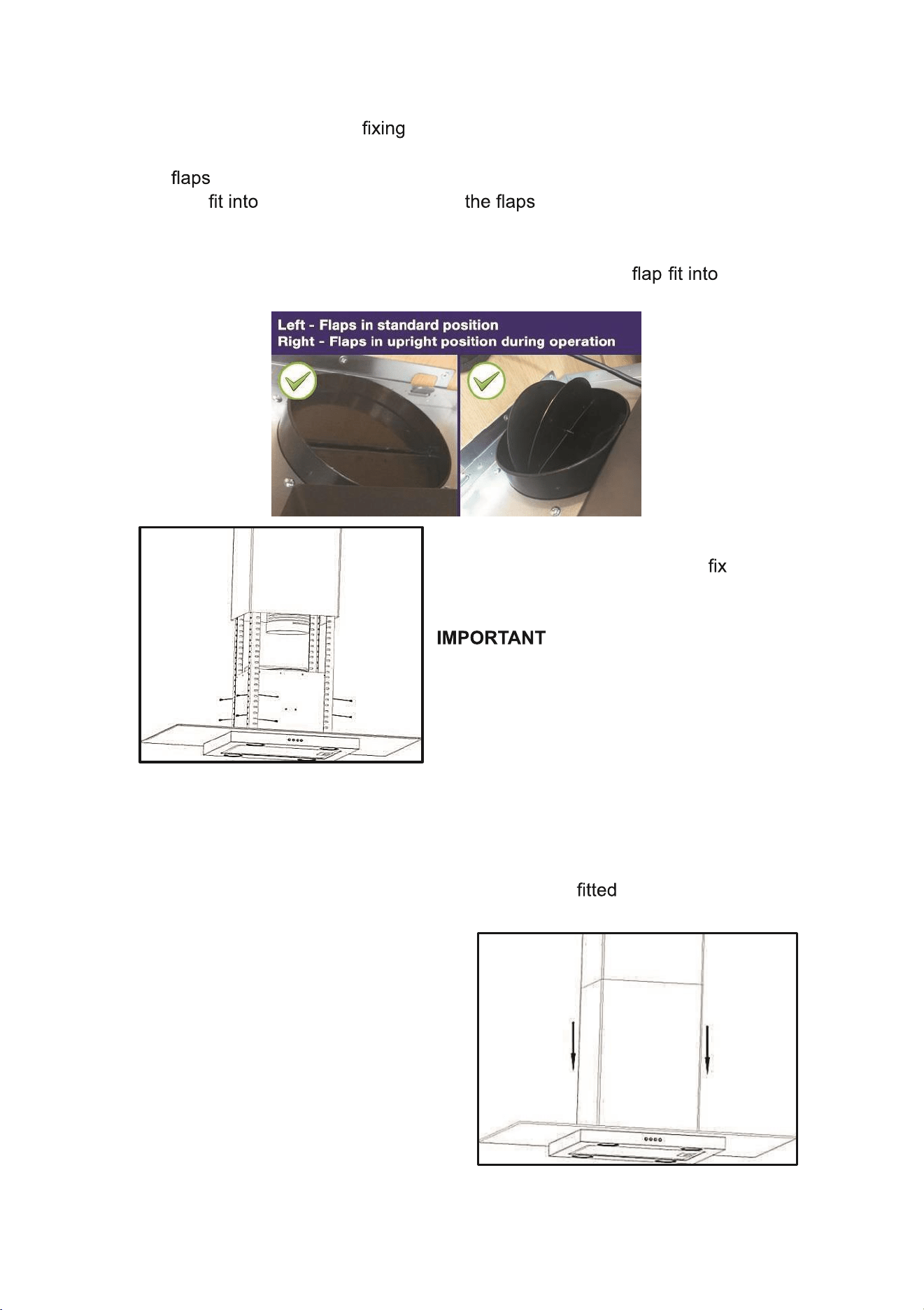
5. On the top of the hood unit, where the air outlet vent is located, the 2 x air
should be carefully installed, bending very slightly so the lugs at each
end the holes This enables to pivot upwards when the unit
is in operation, opening up the outlet fully for the air to pass through.
Please note: The small spindles/lugs at each end of each the
holes on the housing, not the grooves above them:
6. Lift the main body of the cooker hood
onto the angle bar and then it into
position using the 16 x M5 screws.
:
This stage of the installation process MUST
be completed by two people, as one person
must support the weight of the hood until all
16 of the M4 screws have been securely
tightened.
8. The unit should then be connected to a suitable power source, either by
using the supplied plug, or hardwiring the unit into a spur. Please note if
hard wiring the unit, a suitable switch should be in a conveniently
accessible position.
9. Remove the hanging hook and
then slide the lower chimney
section downwards, until it rests
against the main body of the
cooker hood.
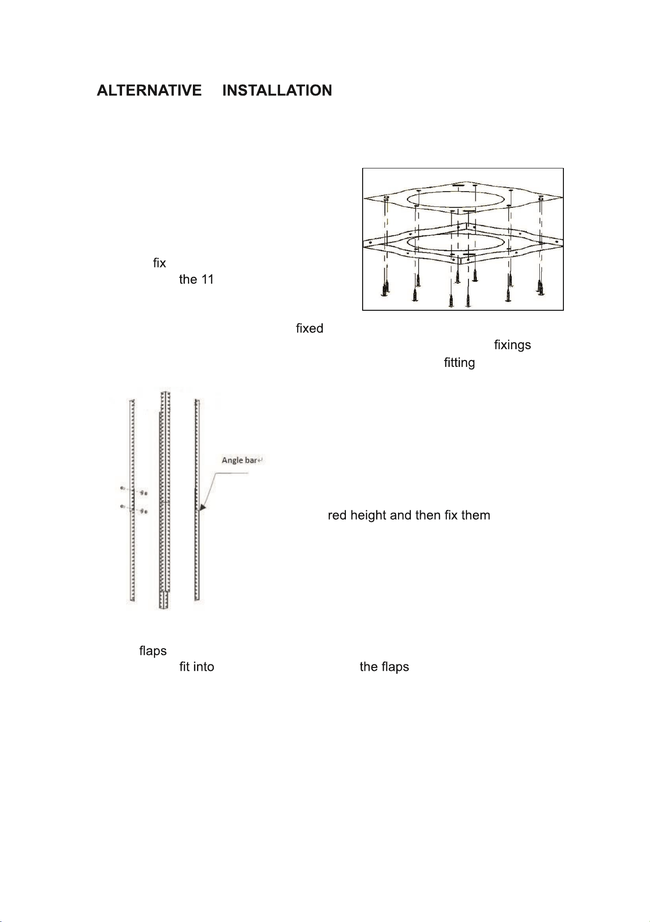
9
FOR MINIMUM CHIMNEY
LENGTH
Do not connect the hood to the mains supply before installing it.
1. Position the hanging plate on the ceiling
and then mark the position of the screw
holes with a pencil.
Securely the hanging plate to the
ceiling, using x ST4 (30 mm)
screws.
Please ensure that the bracket is in a way it would support the weight of
the hood. Depending on the construction of the ceiling, alternative may
be required. 6 x expansion bolts are also provided to allow to concrete.
2. Calculate the length of the angle bars
according to the overall height of the hood
required. Extend the angle bars to the
requi in position
using the 16 x M5 screws. The angle bars
must have an overlap of at least 100mm.
3. On the top of the hood unit , where the air outlet vent is located, the 2 x
air should be carefully installed, bending very slightly so the lugs at
each end the holes This enables to pivot upwards when
the unit is in operation, opening up the outlet fully for the air to pass
through
.

10
Please note: The small
spindles/lugs at each end of
each holes on
the housing, not the grooves
above them.
4. Securely
using 16 x M5(10mm) screws, and
connect the outlet with the exhaust pipe (If
venting externally)
5. Slide the inner chimney and outer
chimney onto the angle bars.
7. If externally venting, connect the
exhaust pipe to the hanging plate.
The angle bar should then be to the
hanging plate using the 8 x M5 screws.
: This stage of the installation process MUST be completed by two
people, as one person must support the weight of the hood until all the screws
have been securely tightened.
8. The unit should then be connected to a
suitable power source, either by using the
supplied plug, or hardwiring the unit into a
spur. Please note if hardwiring the unit, a
suitable switch should be in a
conveniently accessible position.
9. Slide the inner chimney up, and use 4 x
self-tapping screws to connect the inner
chimney with the hanging plate, then the
installation is complete .
11
CARBON (Available Separately)
Activated carbon can be used to trap odours, and must be used if the
unit is not vented externally. These are available from the same stockist the
hood was purchased from under reference: eIQTMCARBONCURV
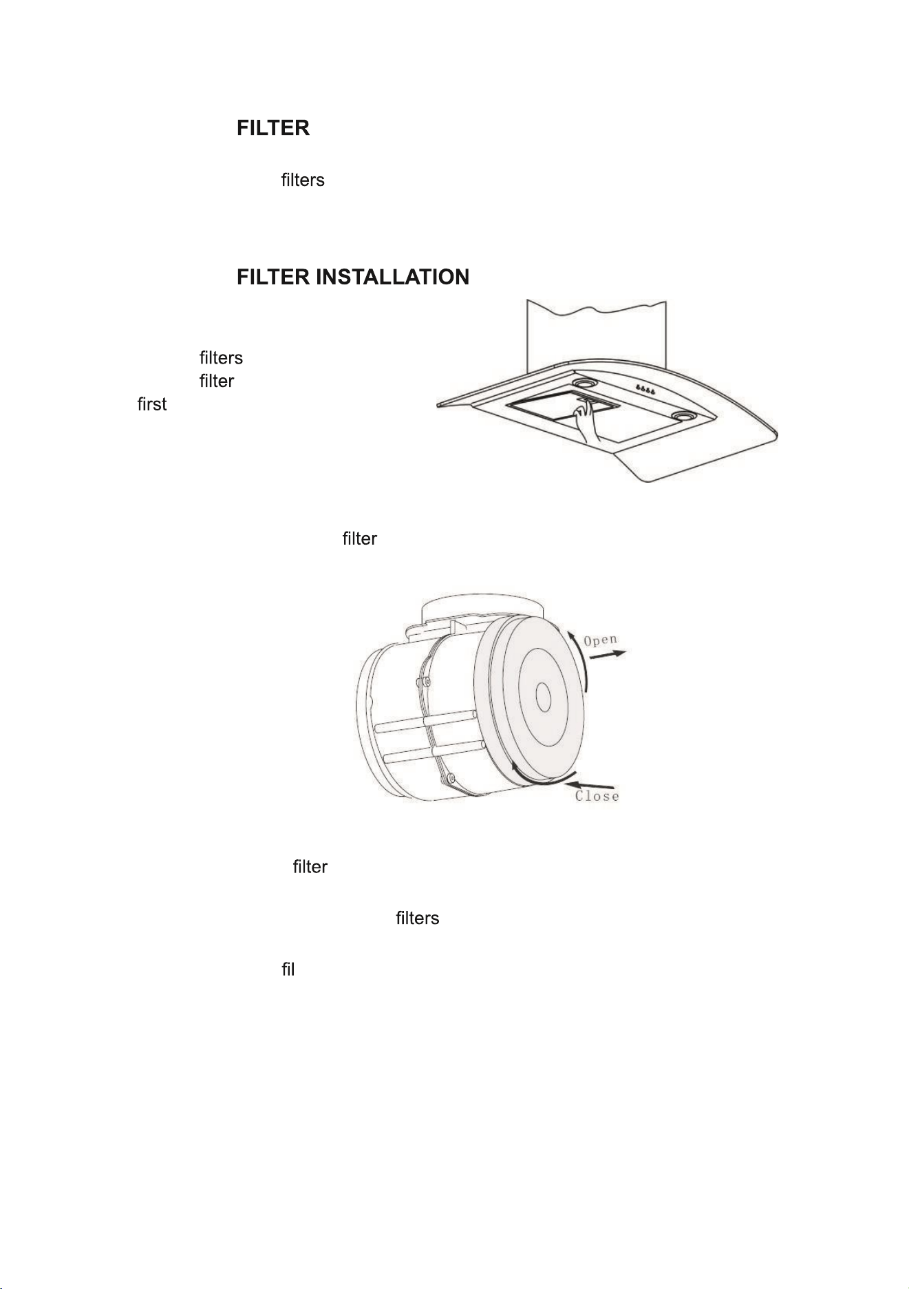
CARBON
In order to install the activated
carbon , the aluminium
grease should be removed
. Press the lock and pull it
downward as below:
Put the activated carbon onto the end of the motor unit and turn it in
clockwise direction. Repeat the same on the other side (see diagram)
NOTE:
• Make sure the is securely locked. Otherwise, it could loosen and
cause damage to the unit.
• When the activated carbon are attached, the suction power will be
reduced.
• The charcoal ter cannot be washed or recycled. It should be changed at
three or six month intervals, depending on the amount of use the hood
receives. Replacements are available from the stockist you purchased the
hood from.
12
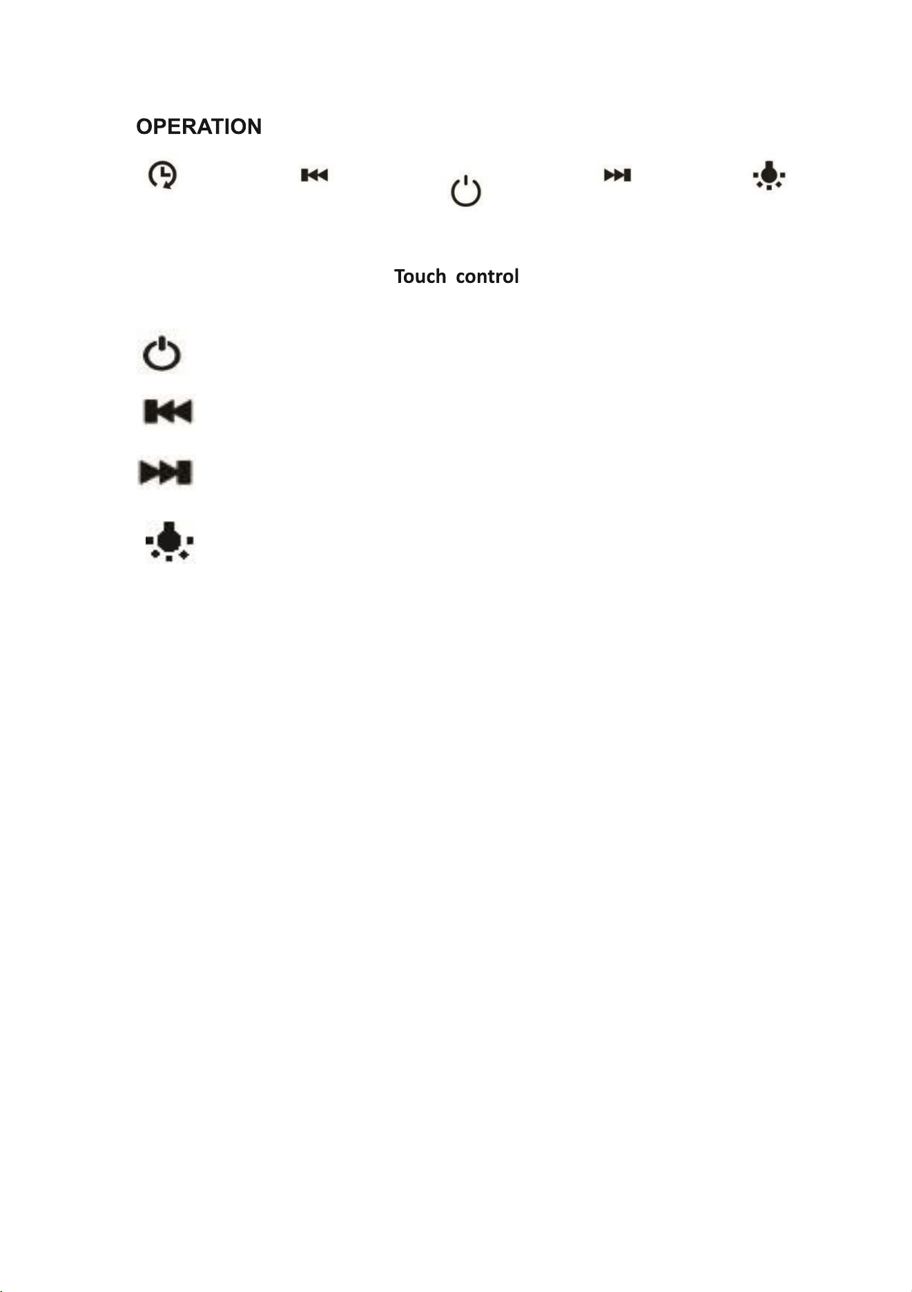
ON/OFF BUTTON
Press this key to turn the power on and off.
FAN SPEED DOWN BUTTON
While the fan is operating, press this key to decrease the power one level.
POWER UP BUTTON
While the fan is operating press this key to increase the power one level.
LIGHT BUTTON
Press once to turn the lights on, press again to turn the lights off.
NOTE:
The display will light at half power when the hood is turned on, and the buttons
will illuminate fully when they are touched.
If no input is received by the control panel for 2 minutes, the display
illumination will turn off until a button is pressed.
13
MAINTENANCE
Before cleaning, switch the unit off and pull out the plug, or switch off at the
relevant mains switch. If the unit has been hard-wired in. Make sure the unit has
no power being fed to it.
REGULAR CLEANING
Use a soft cloth moistened with hand-warm mildly soapy water or household
cleaning detergent. Never use metal pads, chemicals, abrasive material or a
stiff brush to clean the unit.
Note! Do not use a steam- cleaner to clean the hood; electrical components
could be damaged or short-circuit as a result.
CLEANING OF ALUMINIUM GREASE
ESSENTIAL NOTE: Clean the month; an excessive build-up of
grease can become a hazard. The collects grease, smoke and dust,
so the directly affects the the cooker hood. If it’s not cleaned,
the grease residue (potentially ) will saturate on the .
Remove the as shown in the Installation section. Clean it with a soft
nylon brush in a mild solution of warm water and a small amount of washing
up liquid. Washing up liquid alone should not be used. After cleaning, allow the
to drain and then dry thoroughly.
。
The grease may also be dishwasher cleaned; using a 60 C program, with
upright (short sides upright) in the lower basket. Please be aware
some dishwasher cleaning agents can permanently discolour the , though
this will not affects its performance.
Replacement grease available from the same stockist from which
you purchased the hood: eiQTMGREASE3
REPLACEMENT OF ACTIVE CARBON
These are only required in units that have been installed in recirculation mode
This ter traps odours and must be replaced ideally every 3- 6 months
depending on how frequently the cooker hood has been used. They are not
washable or reusable.
Reference: eIQTMCARBONCURV - Carbon Filter Pack
14
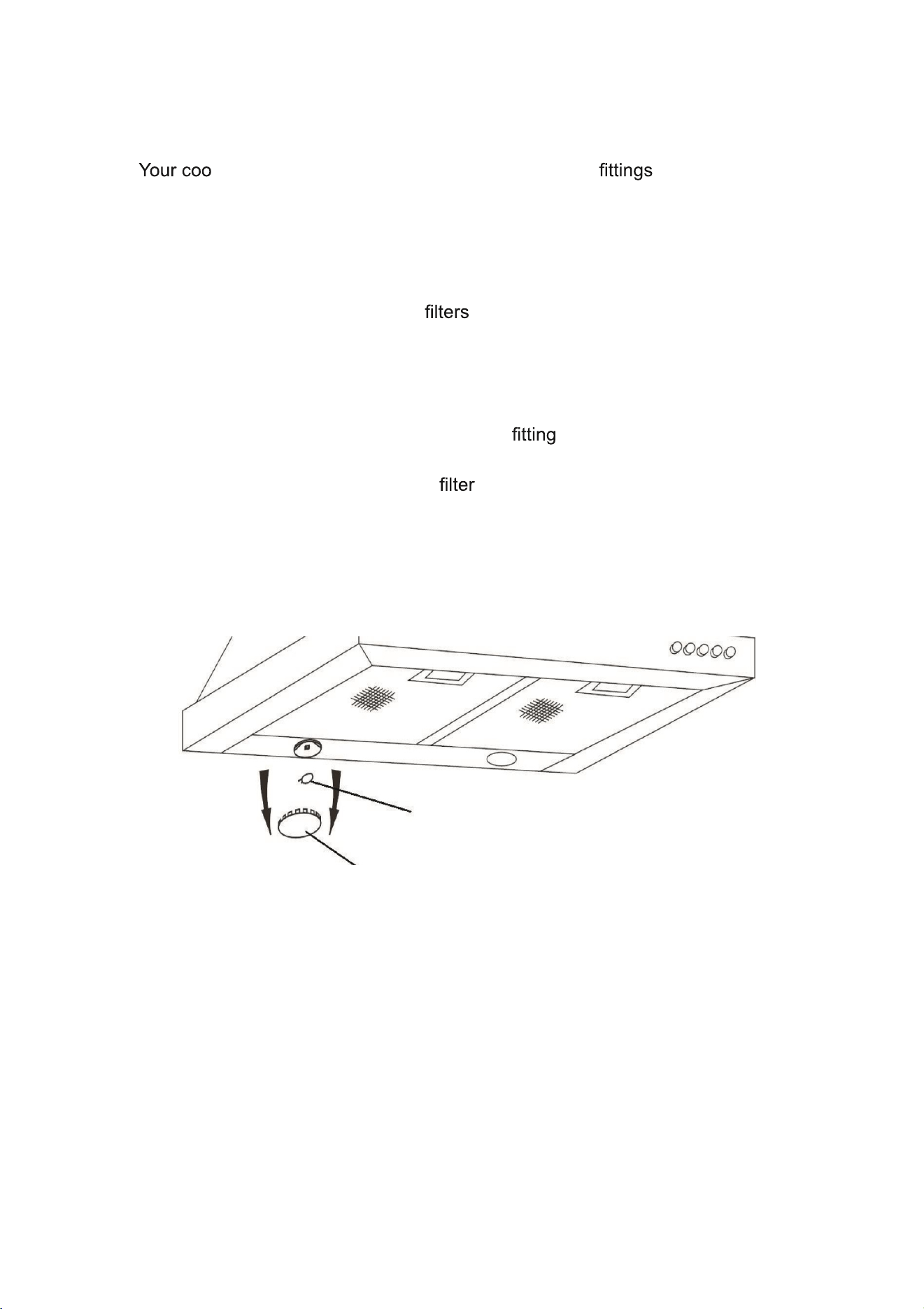
LIGHT BULB REPLACEMENT
ker hood is supplied with 4 long life LED light , Although these
are designed to have a very long lifespan ,should one fail, replacements are
available from the supplier of the hood and the guide below can be followed to
replace it.
1. Switch the unit off and ensure it is disconnected from the mains supply.
2. Remove aluminium grease , to prevent them from falling.
3. Use a screwdriver to carefully remove the metal retaining ring, which
holds the glass in place, ensuring the glass lens is not allowed to fall.
4. Remove the LED light bulb and replace with the same type and rated
LED lamp.
5. Hold the glass lens in position on the , and push the retaining ring
back into position to lock the glass in place.
6. Attach the aluminium grease back onto the unit.
15
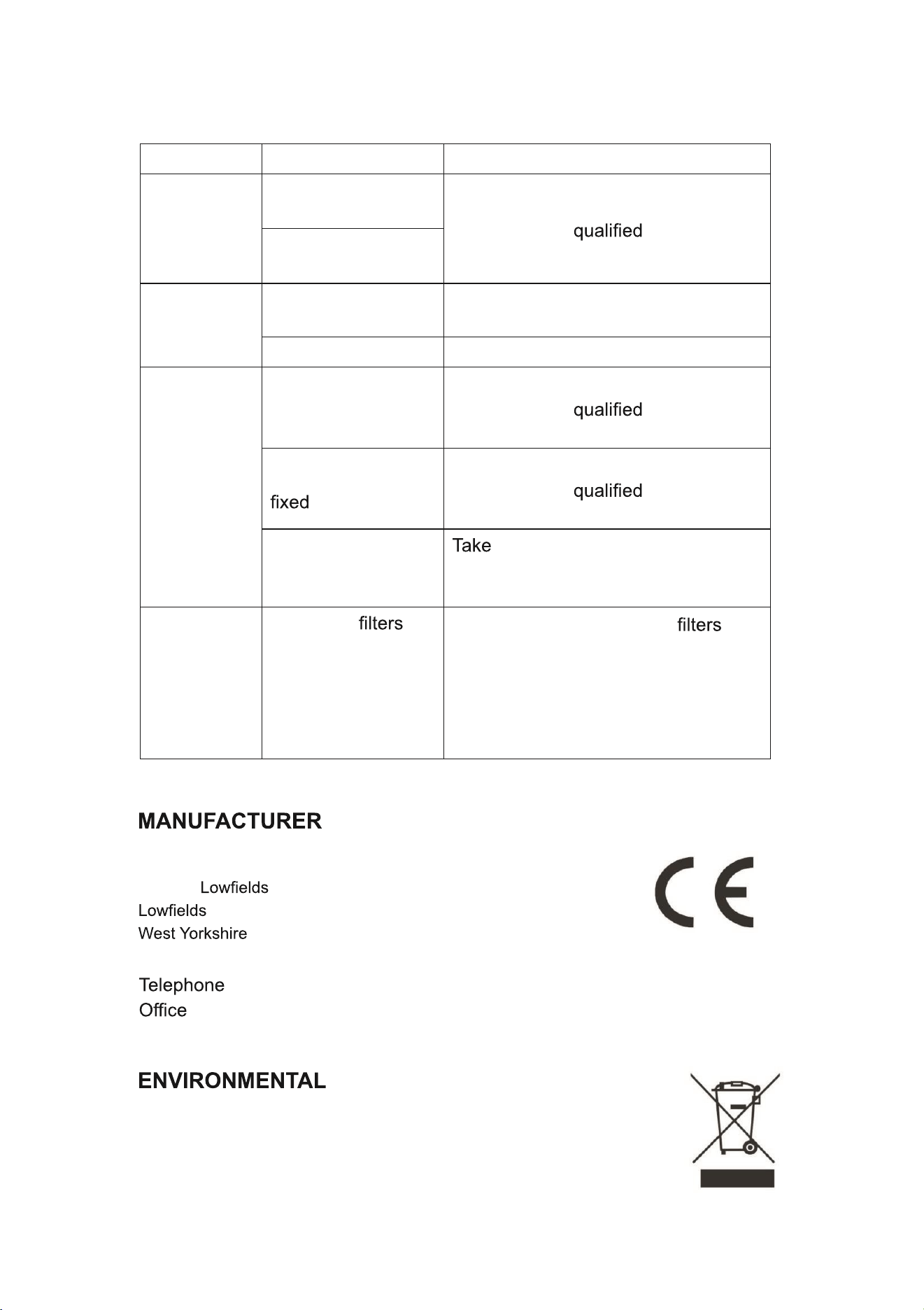
TROUBLESHOOTING
Fault Cause Solution
Light on, but
fan does not
work
The fan blade is
jammed.
Switch off the unit. Repair to be
carried out by service
personnel only.
The motor is
damaged.
Both light
and fan do
not work
Halogen light bulb
blown
Replace the bulb with correct rating.
Power cord loose Plug in to the power supply again.
Excessive
Vibration
The fan blade is
damaged.
Switch off the unit. Repair to be
carried out by service
personnel only.
The fan motor is not
tightly.
Switch off the unit. Repair to be
carried out by service
personnel only.
The unit is not hung
properly on the
bracket.
down the unit and check
whether the bracket is in proper
location.
Suction
performance
not good
1 Grease
clogged
2 Distance between
the unit and the
cooking plane too
great.
1 Clean or replace grease . 2
Adjust the distance to between
70cm and 80cm.
SUPPORT
www.electriQ.co.uk
Unit J6, Business Park
Way, Elland
, HX5 9DA
: 0871 984 4416
Hours: 9:00am to 5:00pm Monday to Friday
PROTECTION
Waste electrical products should not be disposed of with
household waste. Please recycle where facilities exist. Check
with your Local Authority or retailer for recycling advice.
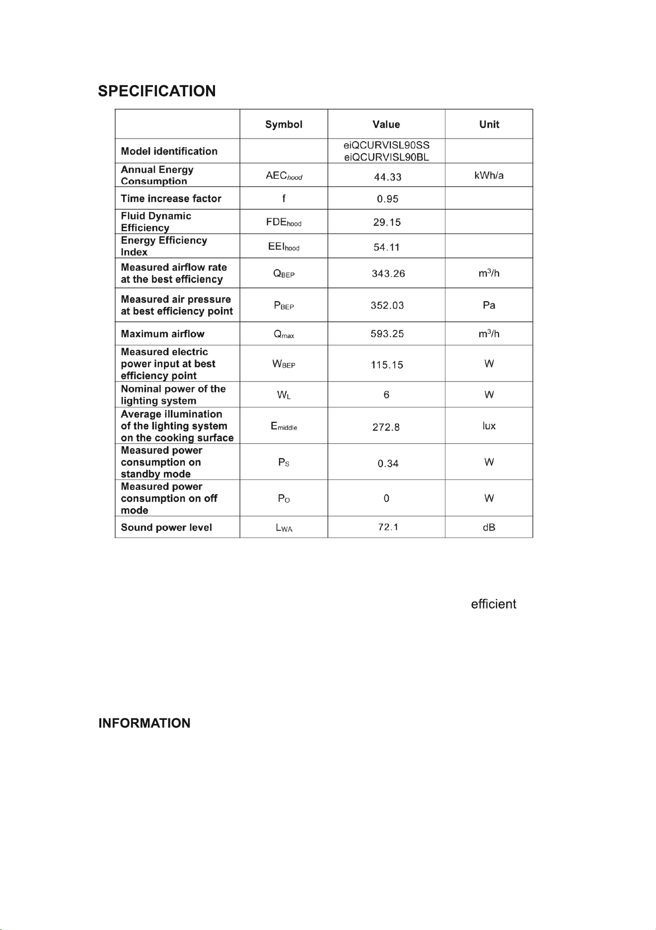
16
The following shows how to reduce total environmental impact (e.g. energy
use) of the cooking process).
(1) Install the cooker hood in a proper place where there is
ventilation.
(2) Clean the cooker hood regularly so as not to block the airway.
(3) Remember to switch off the cooker hood light after cooking.
(4) Remember to switch off the cooker hood after cooking.
FOR DISMANTLING
Do not dismantle the appliance in a way which is not shown in the user
manual. The appliance could not be dismantled by user. At the end of life, the
appliance should not be disposed of with household waste. Check with your
Local Authority or retailer for recycling advice.