1
4
3
6
5
8
7
2(2x)
8
6(2x)
4(2x)
9
2
1
10
Place flat blade
screwdriver in
here and work
pin to the inside.
Grab exposed pin with needle
nose pliers and work out.
Locking Tabs
Latch Assembly
NOTE:
See page 2 for
installation
instructions
of Retactable
Handle (3) into
tool box body.
8
12
54-49-8400
SERVICE PARTS LIST
BULLETIN NO.
MILWAUKEE TOOL
l
www.milwaukeetool.com
13135 W. LISBON RD., BROOKFIELD, WI 53005
Drwg. 9
EXAMPLE:
Component Parts (Small #) Are Included
When Ordering The Assembly (Large #).
0
00
PACKOUT™ Rolling Storage
Sept. 2022
REVISED BULLETIN
WIRING INSTRUCTION
DATE
CATALOG NO.
SPECIFY CATALOG NO. AND SERIAL NO. WHEN ORDERING PARTS
SERIAL
NUMBER
FIG. PART NO. DESCRIPTION OF PART NO. REQ.
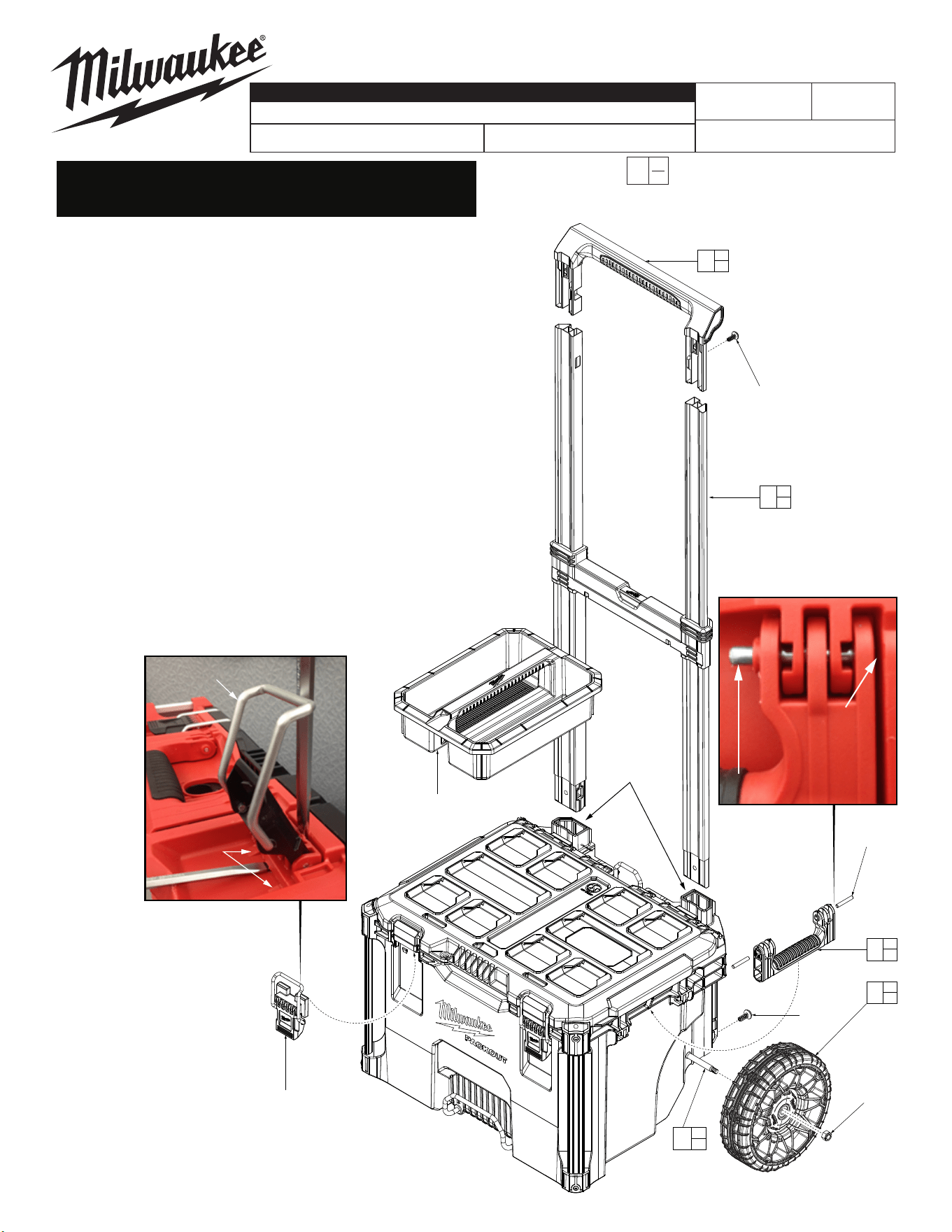
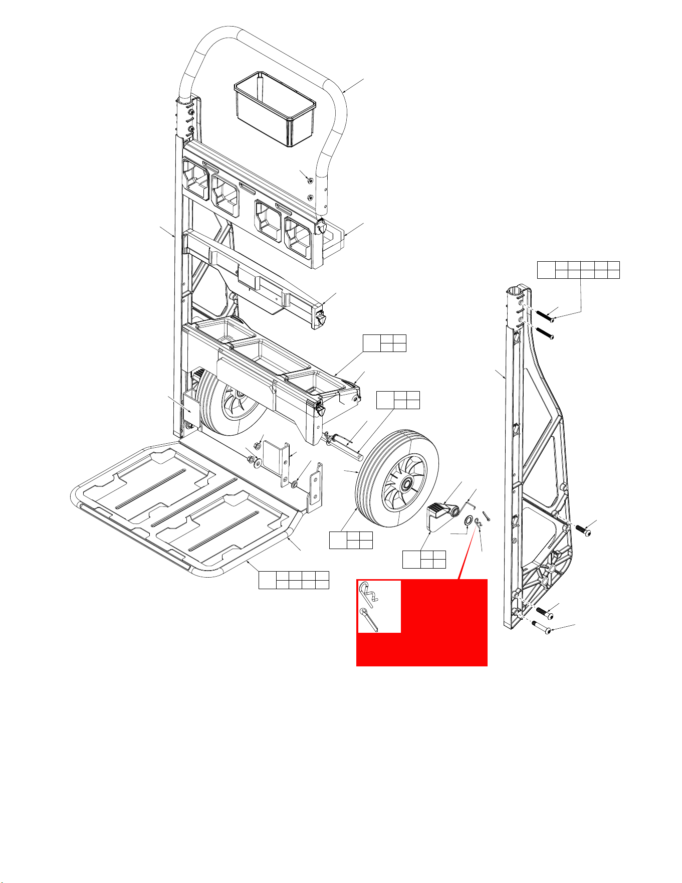
1 --------------- Retractable Handle Grip Service Kit (1)
2 --------------- Screw (2)
3 43-62-8400 Retractable Handle Service Assembly (1)
4 --------------- Screw (2)
5 43-62-8426
Side Handle Svc. Kit (Contains 2 Side Handles and 4 Pins)
(1)
6 --------------- Pin (4)
7 48-22-8098
Wheel Svc. Kit (Contains 2 Wheels and 2 Locking Hex Nuts)
(1)
8 --------------- Locking Hex Nut (2)
9 44-20-8400 Latch Service Assembly (Set of 2) (1)
10 31-01-8400 Storage Tray (1)
11 43-44-8400 Lid Gasket (Not Shown) (1)
12 42-12-8426
Axle Svc. Kit (Contains 1 Axle and 2 Locking Hex Nuts)
(1)
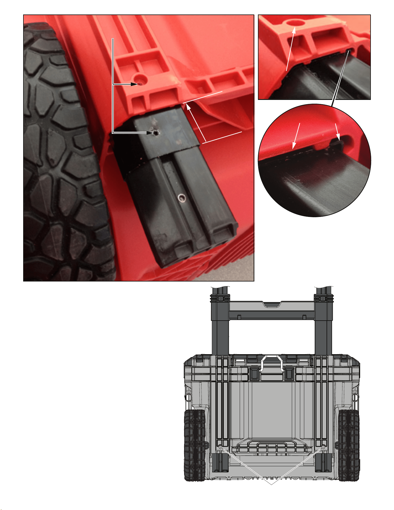
As an aid to removing a damaged Latch
Assembly (9), use two large at blade
screwdrivers. Push blades between parts
as shown. Twist both screwdrivers at same
time to force the blades into opening
and work the latch assembly over the
two locking tabs.
To install a new latch assembly,
position entire latch assembly over
locking tabs with the two top lugs
partially inserted in 'catch cavity' of
main housing. Engage latch bar
onto lid and gently press latch lever
to slide assembly over two locking
tabs and into place.
This removal and installation process will be the same
where other service latches are oered in this system.
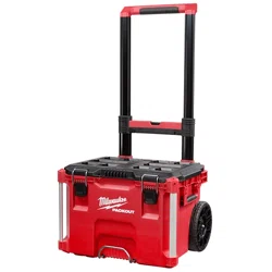
48-22-8426 PACKOUT™ Rolling Tool Box Page 1
48-22-8410 PACKOUT™ Flat Dolly Page 3
48-22-8415 PACKOUT™ 2 Wheel Dolly Page 4
48-22-8428 PACKOUT™ Rolling Tool Chest Page 5
48-22-8426 PACKOUT™ Rolling Tool Box
As an aid to installation, collapse the
Retractable Handle Assembly (3).
Properly orient the assembly and insert
both sides into tool box channels.
Holes of Retractable Handle Assembly (3)
must line up with holes on the back of tool
box body prior to securing with screws (4).
Extend Retractable Handle Assembly (3) beyond
bottom opening in tool box to see the holes that
must line up prior to securing with screws (4).
Push assembly back into channel so
bottom of handle section shown is
flush with bottom of channel. This
should be very close to aligning the
holes. To be sure, a thin pick can be
used in hole to make adjustments.
Push this area
into channel so
bottom is flush
to bottom of box
Both surfaces to be flush
Insert thin pick to
assure holes line up
Screws (4)
Rear View
2
3
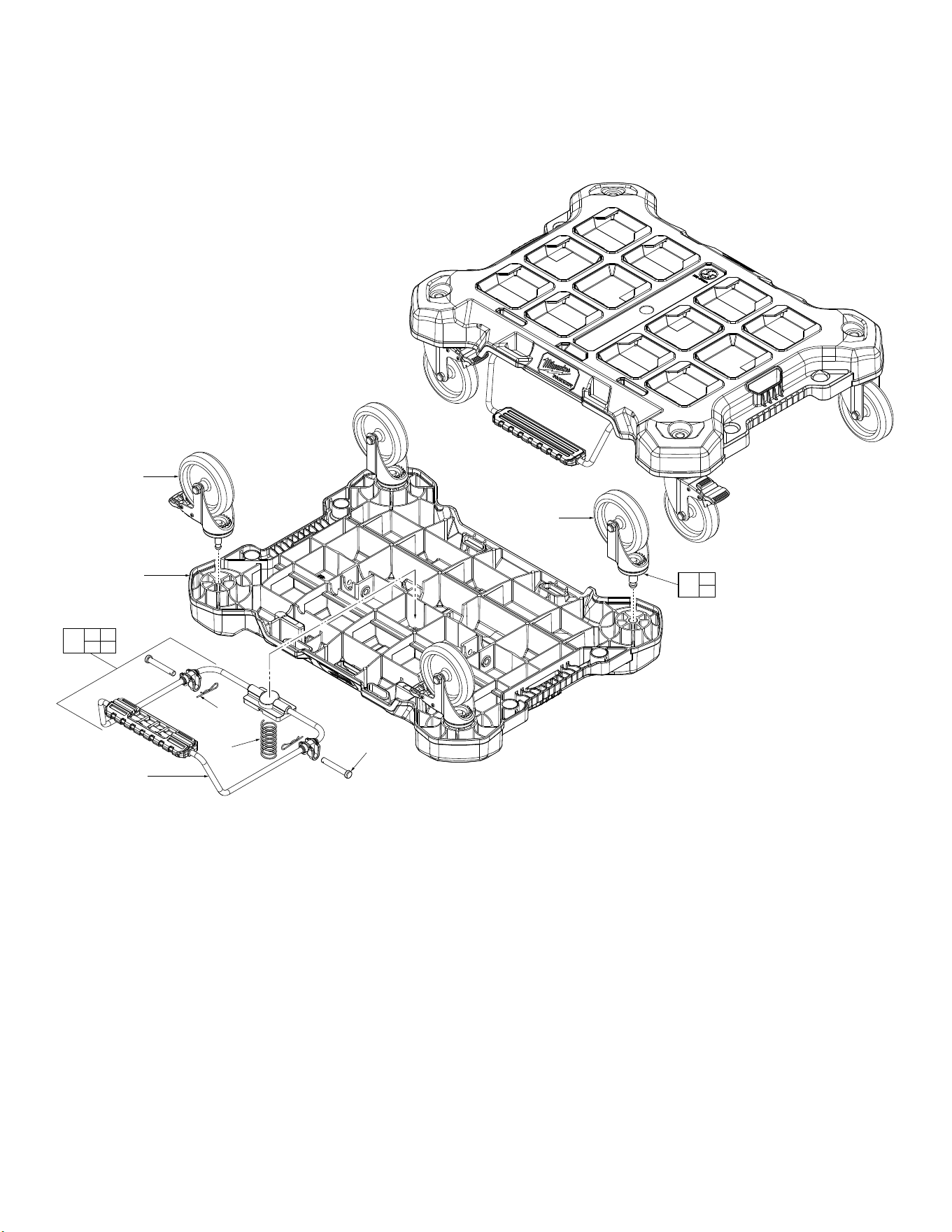
Locking Casters (1) are to be
assembled to the front of the
PACKOUT™ Dolly Body (3).
Front of the dolly body is
determined by the logo plate.
2
(2x)
1
(2x)
3
4a
4c
4b
4d
4a 4b
4c 4d
4
1
2
5
FIG. PART NO. DESCRIPTION OF PART NO. REQ.
1 --------------- Locking Swivel Caster (2)
2 --------------- Swivel Caster (2)
3 --------------- Dolly Base (1)
4 14-04-8410 Dolly Foot Brake Kit (1)
4a --------------- Dolly Foot Brake (1)
4b --------------- Spring (1)
4c --------------- Cotter Pin (2)
4d --------------- Retaining Pin (2)
5 45-94-8410 Swivel Caster Kit (Set of 4) (1)
48-22-8410 PACKOUT™ Flat Dolly
4
48-22-8415 PACKOUT™ 2 Wheeled Dolly
FIG. PART NO. DESCRIPTION OF PART NO. REQ.
1 --------------- Handle (1)
2 --------------- 20 x 1.875" Bolts (4)
3 --------------- 3/8-16 x 2 Bolts (2)
4 --------------- Axle (1)
5 --------------- 3/8-16 Lock Nut (6)
6 --------------- Wheel (2)
7 --------------- Base Plate (1)
8 --------------- Washer (2)
9 --------------- Nylon Shoulder Washer (2)
10 --------------- 3/8-16 x 1.75" Bolts (2)
11 --------------- 5/8" Bushing Washers (6)
12 --------------- Cotter Pin (4)
13 --------------- 3/8-16 x 1.5" Bolts (2)
14 --------------- Right Spring (Not Shown) (1)
15 31-52-8415A Toe Plate Lock Right (Not Shown) (1)
16 31-01-8415 Bottom Tray (1)
17 31-86-8415 Logo Cross Member (1)
18 --------------- Side Frame (2)
19 31-10-8415 PACKOUT Cross Member (1)
20 --------------- Handle Nut (4)
21 --------------- Right Lock/Fender Assembly (1)
FIG. PART NO. DESCRIPTION OF PART NO. REQ.
22 --------------- Left Lock/Fender Assembly (1)
23 --------------- Toe Plate Lock Left (Not Shown) (1)
24 31-01-8415 Bottom Tray Kit (1)
25 ---------------- Left Spring (Not Shown) (1)
26 31-52-8415 Toe Plate Lock Kit (1)
27 45-94-8415 Wheel Kit (1)
28 42-12-8415 Axle Kit (1)
29 42-36-8415 Toe Plate Kit (1)
30 14-46-8415 Hardware Kit (1)
24
5 13
16
29
3 5 7 8
9 10 21 22
30
2 3 5 8 9
10 11 13 20
27
6 11
12
28
4 11
12
Hitch
Pin
Cotter
Pin
Early versions of
the 2 Wheel Dolly
utilized four Hitch
Pins (12) on Axle
(4). When servic-
ing this dolly, it is
recommended to replace the
Hitch Pins with Cotter Pins.
Check local hardware store.
18
2
(x4)
26
14 15
23 25
25
23
4
16
19
20
(x4)
1
17
13
(x2)
10
(x2)
12
(x4)
11
(x6)
6
(x2)
3
(x2)
7
22
9 (x2)
5 (x6)
8 (x2)
21
18
5
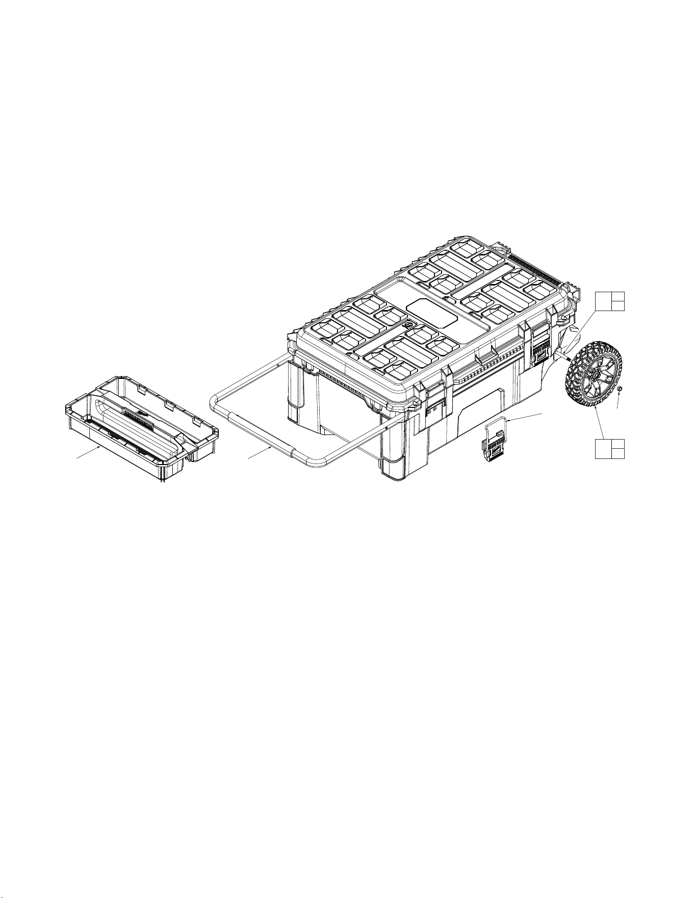
48-22-8428 PACKOUT™ Rolling Tool Chest
FIG. PART NO. DESCRIPTION OF PART NO. REQ.
1 43-62-8428 Handle Service Kit (Handle and 2 Screws) (1)
2 42-12-8426 Axle Service Kit (Axle and 2 Nuts) (1)
3 45-94-8426 Wheel Service Kit (2 Wheels) (1)
4 31-01-8428 Tool Chest Tray (1)
5 44-20-8428 Latch Service Kit (2 Latches) (1)
7 43-44-8428 Lid Gasket (Not Shown) (1)
8 --------------- Hex Nut (2)
8
2
8
(2x)
8
3
5
(2x)
4
1
