V 2.0
Quick Start Guide
130 DUAL VCA
Legendary Analog Dual VCA Module for Eurorack
2 3Quick Start Guide130 DUAL VCA
(EN) Safety Instruction
1. Please read and follow all
instructions.
2. Keep the apparatus away from
water, except for outdoor products..
3. Clean only with a dry cloth.
4. Do not block any ventilation
openings. Install in accordance with the
manufacturer’s instructions.
5. Do not install near any heat
sources such as radiators, heat
registers, stoves or other apparatus
(including ampliers) that
produce heat.
6. Use only attachments/accessories
specied by the manufacturer.
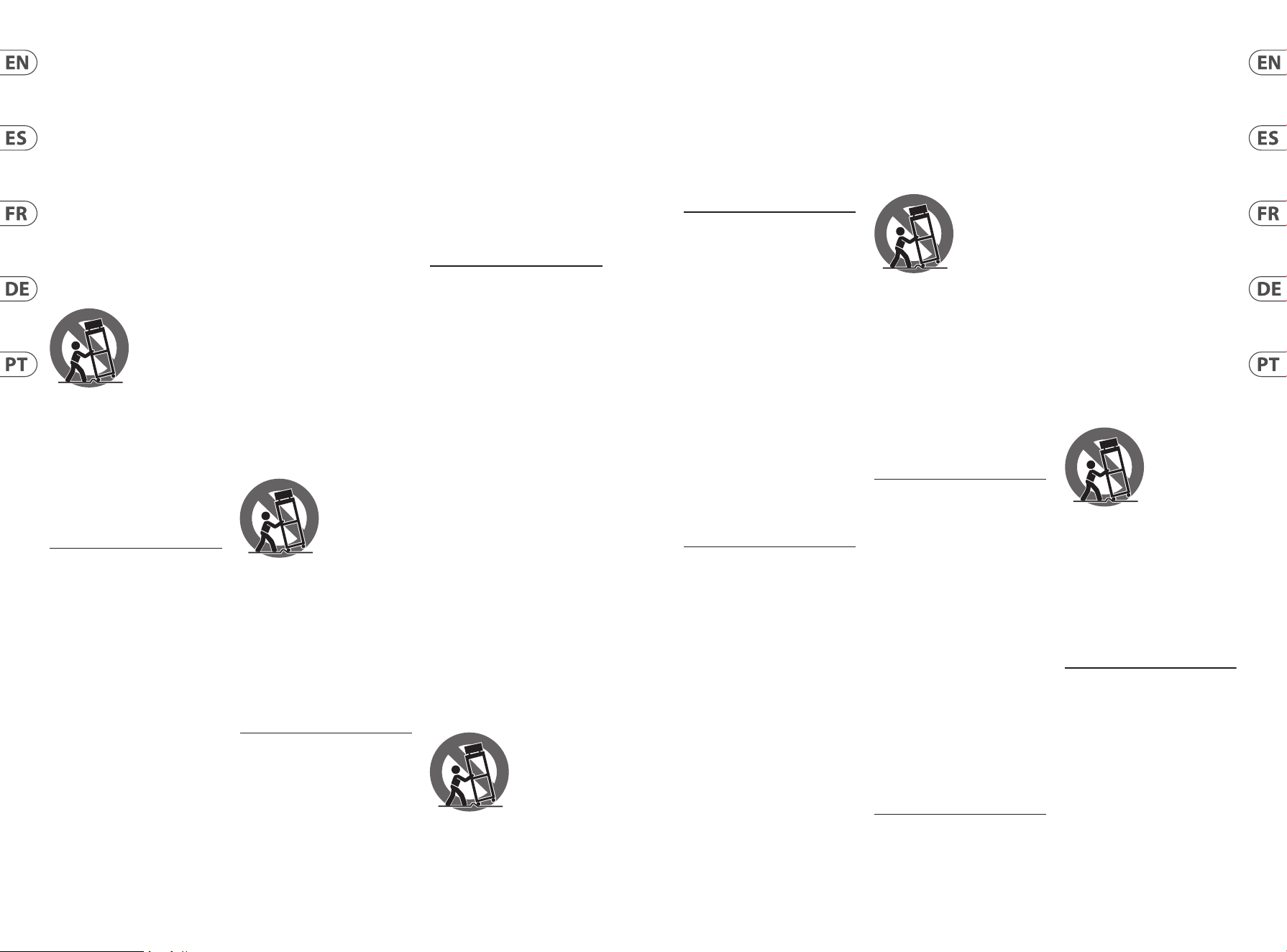
7. Use only
specied carts,
stands, tripods,
brackets, or tables.
Use caution to
prevent tip-over
when moving the cart/apparatus
combination.
8. Avoid installing in conned spaces
like bookcases.
9. Do not place near naked ame
sources, such as lighted candles.
10. Operating temperature range 5°
to 45°C (41° to 113°F).
LEGAL DISCLAIMER
Music Tribe accepts no liability for
any loss which may be suered by
any person who relies either wholly
or in part upon any description,
photograph, or statement contained
herein. Technical specications,
appearances and other information
are subject to change without notice.
All trademarks are the property
of their respective owners. Midas,
Klark Teknik, Lab Gruppen, Lake,
Tannoy, Turbosound, TC Electronic,
TC Helicon, Behringer, Bugera, Aston
Microphones and Coolaudio are
trademarks or registered trademarks
of Music Tribe Global Brands Ltd.
© Music Tribe Global Brands Ltd.
2024 All rights reserved.
LIMITED WARRANTY
For the applicable warranty terms
and conditions and additional
information regarding Music Tribe’s
Limited Warranty, please see
complete details online at community.
musictribe.com/support.
(ES)
Instrucción de seguridad
1. Por favor, lea y siga todas las
instrucciones.
2. Mantenga el aparato alejado
del agua, excepto para productos
destinados al uso en exteriores.
3. Limpie solo con un paño seco.
4. No bloquee ninguna abertura de
ventilación. Instale de acuerdo con las
instrucciones del fabricante.
5. No instale cerca de fuentes de
calor como radiadores, registros
de calor, estufas u otros aparatos
(incluyendo amplicadores) que
generen calor.
6. Utilice solo accesorios
especicados por el fabricante.
7. Use solo
carros, soportes,
trípodes, soportes
o mesas
especicados.
Tenga precaución
para evitar el vuelco al mover la
combinación carro/aparato.
8. Evite la instalación en espacios
connados como estanterías.
9. No colocar cerca de fuentes de
llama desnuda, como velas encendidas.
10. Rango de temperatura de
funcionamiento de 5° a 45° C
(41° a 113° F).
NEGACIÓN LEGAL
Music Tribe no admite ningún tipo
de responsabilidad por cualquier
daño o pérdida que pudiera sufrir
cualquier persona por conar total
o parcialmente en la descripciones,
fotografías o armaciones
contenidas en este documento.
Las especicaciones técnicas,
imágenes y otras informaciones
contenidas en este documento están
sujetas a modicaciones sin previo
aviso. Todas las marcas comerciales
que aparecen aquí son propiedad
de sus respectivos dueños. Midas,
Klark Teknik, Lab Gruppen, Lake,
Tannoy, Turbosound, TC Electronic,
TC Helicon, Behringer, Bugera, Aston
Microphones y Coolaudio son marcas
comerciales o marcas registradas
de Music Tribe Global Brands Ltd.
© Music Tribe Global Brands Ltd.
2024 Reservados todos los derechos.
GARANTÍA LIMITADA
Si quiere conocer los detalles y
condiciones aplicables de la garantía
así como información adicional sobre
la Garantía limitada de Music Tribe,
consulte online toda la información
en la web community.musictribe.
com/support.
(FR) Consignes de sécurité
1. Veuillez lire et suivre toutes les
instructions.
2. Gardez l'appareil éloigné de l'eau,
sauf pour les produits destinés à une
utilisation en extérieur.
3. Nettoyez uniquement avec un
chion sec.
4. Ne bloquez aucune ouverture de
ventilation. Installez conformément
aux instructions du fabricant.
5. N'installez pas près de sources de
chaleur telles que radiateurs, grilles de
chaleur, cuisinières ou autres appareils
(y compris les amplicateurs) qui
produisent de la chaleur.
6. Utilisez uniquement les
accessoires spéciés par le fabricant.
7. Utilisez
uniquement des
chariots, des
supports, des
trépieds, des
supports ou des
tables spéciés. Faites attention pour
éviter le renversement lors du
déplacement de la combinaison
chariot/appareil.
8. Évitez l'installation dans
des espaces connés comme les
bibliothèques.
9. Ne pas placer près de sources
de amme nue, telles que des
bougies allumées.
10. Plage de température de
fonctionnement de 5° à 45° C
(41° à 113)
DÉNI LÉGAL
Music Tribe ne peut être tenu pour
responsable pour toute perte pouvant
être subie par toute personne se
ant en partie ou en totalité à
toute description, photographie
ou armation contenue dans ce
document. Les caractéristiques,
l’apparence et d’autres informations
peuvent faire l’objet de modications
sans notication. Toutes les marques
appartiennent à leurs propriétaires
respectifs. Midas, Klark Teknik,
Lab Gruppen, Lake, Tannoy,
Turbosound, TC Electronic, TC Helicon,
Behringer, Bugera, Aston Microphones
et Coolaudio sont des marques ou
marques déposées de Music Tribe
Global Brands Ltd. © Music Tribe Global
Brands Ltd. 2024 Tous droits réservés.
GARANTIE LIMITÉE
Pour connaître les termes et conditions
de garantie applicables, ainsi que
les informations supplémentaires et
détaillées sur la Garantie Limitée de
Music Tribe, consultez le site Internet
community.musictribe.com/support.
(DE) Wichtige
Sicherheitshinweise
1. Bitte lesen Sie alle Anweisungen
sorgfältig durch und befolgen
Sie diese.
2. Halten Sie das Gerät von Wasser
fern, außer für Produkte, die für den
Außeneinsatz vorgesehen sind.
3. Reinigen Sie es nur mit einem
trockenen Tuch.
4. Blockieren Sie keine
Belüftungsönungen. Installieren
Sie gemäß den Anweisungen
des Herstellers.
5. Installieren Sie nicht in der Nähe
von Wärmequellen wie Heizkörpern,
Heizregistern, Öfen oder anderen
Geräten (einschließlich Verstärkern),
die Wärme erzeugen.
6. Verwenden Sie nur Zubehörteile,
die vom Hersteller angegeben sind.
7. Verwenden
Sie nur
spezizierte
Wagen, Ständer,
Stative,
Halterungen oder
Tische. Achten Sie darauf, beim
Bewegen der Wagen-Geräte-
Kombination ein Umkippen
zu vermeiden.
8. Vermeiden Sie die Installation in
beengten Räumen wie Bücherregalen.
9. Nicht in der Nähe von oenen
Flammenquellen platzieren,
wie brennende Kerzen.
10. Betriebstemperaturbereich von 5°
bis 45°C (41° bis 113°F).
HAFTUNGSAUSSCHLUSS
Music Tribe übernimmt keine Haftung
für Verluste, die Personen entstanden
sind, die sich ganz oder teilweise auf
hier enthaltene Beschreibungen,
Fotos oder Aussagen verlassen haben.
Technische Daten, Erscheinungsbild
und andere Informationen können
ohne vorherige Ankündigung
geändert werden. Alle Warenzeichen
sind Eigentum der jeweiligen
Inhaber. Midas, Klark Teknik, Lab
Gruppen, Lake, Tannoy, Turbosound,
TC Electronic, TC Helicon, Behringer,
Bugera, Aston Microphones und
Coolaudio sind Warenzeichen oder
eingetragene Warenzeichen der
Music Tribe Global Brands Ltd.
© Music Tribe Global Brands Ltd.
2024 Alle Rechte vorbehalten.
BESCHRÄNKTE GARANTIE
Die geltenden Garantiebedingungen
und zusätzliche Informationen
bezüglich der von Music Tribe
gewährten beschränkten Garantie
nden Sie online unter community.
musictribe.com/support.
(PT) Instruções de
Seguranç Importantes
1. Por favor, leia e siga todas as
instruções.
2. Mantenha o aparelho longe da
água, exceto para produtos destinados
ao uso externo.
3. Limpe apenas com um pano seco.
4. Não bloqueie nenhuma abertura
de ventilação. Instale de acordo com as
instruções do fabricante.
5. Não instale próximo a fontes
de calor, como radiadores, grelhas
de calor, fogões ou outros aparelhos
(incluindo amplicadores) que
gerem calor.
6. Use apenas acessórios
especicados pelo fabricante.
7. Use apenas
carrinhos,
suportes, tripés,
suportes ou mesas
especicados.
Tenha cuidado
para evitar tombamentos ao mover a
combinação carrinho/aparelho.
8. Evite instalar em espaços
connados, como estantes.
9. Não coloque perto de fontes de
chama nua, como velas acesas.
10. Intervalo de temperatura de
operação de 5° a 45° C (41° a 113° F).
LEGAL RENUNCIANTE
O Music Tribe não se responsabiliza
por perda alguma que possa ser
sofrida por qualquer pessoa que
dependa, seja de maneira completa
ou parcial, de qualquer descrição,
fotograa, ou declaração aqui
contidas. Dados técnicos, aparências
e outras informações estão sujeitas
a modicações sem aviso prévio.
Todas as marcas são propriedade
de seus respectivos donos. Midas,
Klark Teknik, Lab Gruppen, Lake,
Tannoy, Turbosound, TC Electronic,
4 5Quick Start Guide130 DUAL VCA
TC Helicon, Behringer, Bugera,
Aston Microphones e Coolaudio
são marcas ou marcas registradas
do Music Tribe Global Brands Ltd.
© Music Tribe Global Brands Ltd.
2024 Todos direitos reservados.
GARANTIA LIMITADA
Para obter os termos de garantia
aplicáveis e condições e informações
adicionais a respeito da garantia
limitada do Music Tribe, favor vericar
detalhes na íntegra através do website
community.musictribe.com/support.
(IT) Istruzioni di sicurezza
importanti
1. Per favore, leggere e seguire tutte
le istruzioni.
2. Mantenere l'apparecchio lontano
dall'acqua, tranne per i prodotti
destinati all'uso all'aperto.
3. Pulire solo con un panno asciutto.
4. Non ostruire alcuna apertura di
ventilazione. Installare in conformità
alle istruzioni del produttore.
5. Non installare vicino a fonti di
calore come termosifoni, bocchette
di calore, fornelli o altri apparecchi
(compresi gli amplicatori) che
producono calore.
6. Utilizzare solo accessori specicati
dal produttore.
7. Usare solo
carrelli, supporti,
treppiedi, stae o
tavoli specicati.
Prestare
attenzione per
evitare il ribaltamento durante lo
spostamento della combinazione
carrello/apparecchio.
8. Evitare l'installazione in spazi
connati come librerie.
9. Non posizionare vicino a fonti di
amma nude, come candele accese.
10. Intervallo di temperatura
di funzionamento da 5° a 45° C
(41° a 113° F)
DISCLAIMER LEGALE
Music Tribe non si assume alcuna
responsabilità per eventuali danni
che possono essere subiti da chiunque
si adi in tutto o in parte a qualsiasi
descrizione, fotograa o dichiarazione
contenuta qui. Speciche tecniche,
aspetti e altre informazioni sono
soggette a modiche senza preavviso.
Tutti i marchi sono di proprietà
dei rispettivi titolari. Midas, Klark
Teknik, Lab Gruppen, Lake, Tannoy,
Turbosound, TC Electronic, TC Helicon,
Behringer, Bugera, Aston Microphones
e Coolaudio sono marchi o marchi
registrati di Music Tribe Global Brands
Ltd. © Music Tribe Global Brands Ltd.
2024 Tutti i diritti riservati.
GARANZIA LIMITATA
Per i termini e le condizioni di garanzia
applicabili e le informazioni aggiuntive
relative alla garanzia limitata di Music
Tribe, consultare online i dettagli
completi su community.musictribe.
com/support.
(NL) Belangrijke
veiligheidsvoorschriften
1. Lees alsjeblieft alle instructies en
volg deze op.
2. Houd het apparaat uit de buurt
van water, behalve voor producten die
bedoeld zijn voor buitengebruik.
3. Reinig alleen met een droge doek.
4. Blokker geen ventilatieopeningen.
Installeer volgens de instructies van de
fabrikant.
5. Installeer niet in de buurt van
warmtebronnen zoals radiatoren,
warmte registers, fornuizen of andere
apparaten (inclusief versterkers) die
warmte produceren.
6. Gebruik alleen accessoires die
door de fabrikant zijn gespeciceerd.
7. Gebruik
alleen
gespeciceerde
karren, standaards,
statieven, beugels
of tafels. Wees
voorzichtig om kantelen te voorkomen
bij het verplaatsen van de kar/
apparaatcombinatie.
8. Vermijd installatie in afgesloten
ruimtes zoals boekenkasten.
9. Plaats niet in de buurt
van naakte vlambronnen,
zoals brandende kaarsen.
10. Bedrijfstemperatuurbereik van 5°
tot 45°C (41° tot 113°F).
WETTELIJKE ONTKENNING
Music Tribe aanvaardt geen
aansprakelijkheid voor enig verlies
dat kan worden geleden door een
persoon die geheel of gedeeltelijk
vertrouwt op enige beschrijving,
foto of verklaring hierin. Technische
specicaties, verschijningen en andere
informatie kunnen zonder voorafgaande
kennisgeving worden gewijzigd. Alle
handelsmerken zijn eigendom van hun
respectievelijke eigenaren. Midas, Klark
Teknik, Lab Gruppen, Lake, Tannoy,
Turbosound, TC Electronic, TC Helicon,
Behringer, Bugera, Aston Microphones
en Coolaudio zijn handelsmerken of
gedeponeerde handelsmerken van
Music Tribe Global Brands Ltd. © Music
Tribe Global Brands Ltd. 2024 Alle
rechten voorbehouden.
BEPERKTE GARANTIE
Voor de toepasselijke
garantievoorwaarden en aanvullende
informatie met betrekking tot de
beperkte garantie van Music Tribe,
zie de volledige details online op
community.musictribe.com/support.
(SE) Viktiga
säkerhetsanvisningar
1. Vänligen läs och följ alla
instruktioner noggrant.
2. Håll apparaten borta från vatten,
förutom för utomhusprodukter.
3. Rengör endast med en torr trasa.
4. Blockera inte några
ventilationsöppningar. Installera enligt
tillverkarens anvisningar.
5. Installera inte nära några
värmekällor som element,
värmeregistrar, spisar eller andra
apparater (inklusive förstärkare) som
genererar värme.
6. Använd endast tillbehör som
anges av tillverkaren.
7. Använd
endast
specicerade
vagnar, ställ, stativ,
fästen eller bord.
Var försiktig för att
undvika att vagnen/
apparatkombinationen tippar när
den yttas.
8. Undvik installation i trånga
utrymmen som bokhyllor.
9. Placera inte nära öppen låga,
såsom tända ljus.
10. Driftstemperaturområde 5° till
45° C (41° till 113° F).
FRISKRIVNINGSKLAUSUL
Music Tribe tar inget ansvar för
någon förlust som kan drabbas av
någon person som helt eller delvis
förlitar sig på någon beskrivning,
fotogra eller uttalande som nns här.
Tekniska specikationer, utseenden
och annan information kan ändras
utan föregående meddelande. Alla
varumärken tillhör respektive ägare.
Midas, Klark Teknik, Lab Gruppen, Lake,
Tannoy, Turbosound, TC Electronic,
TC Helicon, Behringer, Bugera,
Aston Microphones och Coolaudio
är varumärken eller registrerade
varumärken som tillhör Music Tribe Global
Brands Ltd. © Music Tribe Global Brands
Ltd. 2024 Alla Rättigheter reserverade.
BEGRÄNSAD GARANTI
För tillämpliga garantivillkor och
ytterligare information om Music Tribes
begränsade garanti, se fullständig
information online på community.
musictribe.com/support.
(PL) Ważne informacje o
bezpieczeństwie
1. Proszę przeczytać i ścisłe
przestrzegać wszystkich instrukcji.
2. Trzymaj urządzenie z dala
od wody, z wyjątkiem produktów
przeznaczonych do użytku na
zewnątrz.
3. Czyść tylko suchą szmatką.
4. Nie blokuj żadnych otworów
wentylacyjnych. Instaluj zgodnie z
instrukcjami producenta.
5. Nie instaluj w pobliżu źródeł
ciepła, takich jak grzejniki, rejestratory
ciepła, kuchenki lub inne urządzenia
(w tym wzmacniacze), które generują
ciepło.
6. Używaj tylko akcesoriów
określonych przez producenta.
7. Używaj tylko
określonych
wózków, stojaków,
statywów,
uchwytów lub
stołów. Uważaj,
aby zapobiec przewróceniu się wózka/
aparatu podczas przemieszczania.
8. Unikaj instalacji w ciasnych
miejscach, takich jak regały na książki.
9. Nie umieszczaj w pobliżu
źródeł otwartego ognia, takich jak
zapalone świeczki.
10. Zakres temperatury pracy od 5°
do 45°C (41° do 113°F).
ZASTRZEŻENIA PRAWNE
Music Tribe nie ponosi
odpowiedzialności za jakiekolwiek
straty, które mogą ponieść osoby,
które polegają w całości lub w
części na jakimkolwiek opisie,
fotograi lub oświadczeniu
zawartym w niniejszym dokumencie.
Specykacje techniczne, wygląd i
inne informacje mogą ulec zmianie
bez powiadomienia. Wszystkie
znaki towarowe są własnością ich
odpowiednich właścicieli. Midas,
Klark Teknik, Lab Gruppen, Lake,
Tannoy, Turbosound, TC Electronic,
TC Helicon, Behringer, Bugera, Aston
Microphones i Coolaudio są znakami
towarowymi lub zastrzeżonymi
znakami towarowymi rmy Music
Tribe Global Brands Ltd. © Music Tribe
Global Brands Ltd. 2024 Wszystkie
prawa zastrzeżone.
OGRANICZONA GWARANCJA
Aby zapoznać się z obowiązującymi
warunkami gwarancji i dodatkowymi
informacjami dotyczącymi
ograniczonej gwarancji Music Tribe,
zapoznaj się ze wszystkimi szczegółami
w trybie online pod adresem
community.musictribe.com/support.
(JP) 安全指示
1.
すべての指示を読んで、
従ってください。
2. 屋 外 の 製 品 を 除 き 、機 器
を 水 か ら遠 ざ け てください 。
3. 乾 いた布 で のみ清 掃して
ください。
4. 通気口を塞がないでくだ
さ い 。メ ー カ ー の 指 示 に 従 っ
てインストールしてください 。
5. 暖 房 器 、ヒ ー ト レ ジ ス タ
ー 、ス ト ー ブ な ど の 発 熱 機 器
(アンプを含む)の近くには
取り付けないでください。
6. メーカーが指 定したアタ
ッチメント/アクセサリーのみ
使 用してください 。
7. 指定され
たカート、スタ
ン ド 、三 脚 、ブ
ラ ケ ッ ト 、ま た
はテ ーブル の
み 使 用してく
だ さ い 。カ ー ト / 機 器 の 組 み 合
わ せ を 移 動 す る 際 に は 、転 倒
を防ぐよう注 意してくだ
さい。
8. 書棚などの密閉された
空間には設 置しないでくだ
さい。
9. 裸火のような火の元の近
くに置 かないでください 。
6 7Quick Start Guide130 DUAL VCA
10. 動作温度範囲は摂氏 5
度から 45 度 (華氏 41 度から
113 度) です。
法的放棄
ここに含まれる記述、
写真、意見の全体または一
部に依拠して、いかなる人
が損害を生じさせた場合に
も、
MUSIC Tribe は一切の賠償
責任を負いません。技術仕
様、外観およびその他の情報
は予告なく変更になる場合
があります。商標はすべて、
それぞれの所有者に帰属し
ます。
Midas、Klark Teknik、
Lab Gruppen、Lake、Tannoy、
Turbosound、TC Electronic、
TC Helicon、Behringer、Bugera、
Aston
Microphones
および Coolaudio は
Music Tribe Global Brands Ltd. の商標
または登録商標です。
© Music
Tribe Global Brands Ltd. 2024
無断転
用禁止。
限定保証
適用される保証条件と
Music Tribe の限定保証に関
す る 概 要 に つ い て は 、オ ン
ライン上
community.musictribe.
com/support
にて詳 細をご確 認
ください。
(CN) 安全须知
1.
请阅读, 保存, 遵守所有
的说明, 注意所有的警示。
2. 请勿在靠近水的地方使用
本产品。
3. 请用干布清洁本产品。
4. 请只使用厂家指定的附属
设备和配件。 不要堵塞任何
通风口。按照制造商的说明进
行安装。
5. 请只使用厂
家指定的或随
货销售的手推
车, 架子, 三角
架, 支架和桌
子等。 若使用手推车来搬运设
备, 请注意安全放置设备, 以
避免手推车和设备倾倒而
受伤。
6. 请勿安装在密闭空间, 如书
柜或类似装置。
7. 请勿将本产品安装在热源
附近, 如暖气片, 炉子或其它产
生热量的设备 (包括功放器)
。 产品上不要放置裸露的火焰
源, 如点燃的蜡烛。
8. 如果液体流入或异物落入
设备内, 设备遭雨淋或受潮, 设
备不 能正常运作或被摔坏等,
设备受损需进行维修时, 所有
维修均须由 合格的维修人员
进行维修。
法律声明
对于任何因在此说明书提到
的全部或部份描述、 图片或
声明而造成的损失,
Music Tribe
不负任何责任。 技术参数和
外观若有更改, 恕不另行通
知。 所有的商标均为其各自所
有者的财产。
Midas, Klark Teknik,
Lab Gruppen, Lake, Tannoy,
Turbosound, TC Electronic, TC Helicon,
Behringer, Bugera, Aston Microphones
和 Coolaudio 是 Music Tribe Global
Brands Ltd.
公司的商标或注册
商标。
© Music Tribe Global Brands
Ltd. 2024
版权所有。
保修条款
有关音乐集团保修的适用条
款及其它相关信息, 请登陆
community.musictribe.com/support
网站查看完整的详细信息。
8 9Quick Start Guide130 DUAL VCA
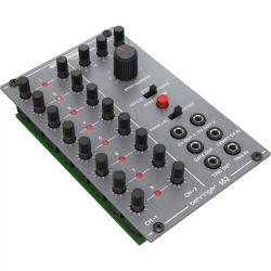
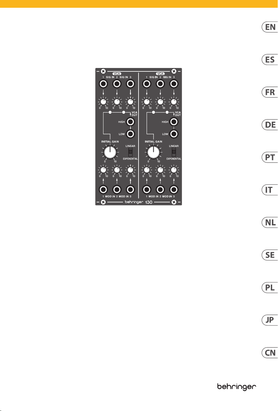
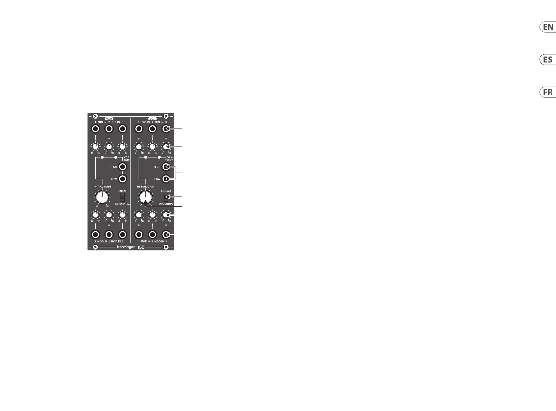
130 DUAL VCA Controls
(1)
(2)
(4)
(6)
(7)
(5)
(3)
(1) SIG IN input jacks accept audio signals over cables with 3.5 mm TS connectors.
(2) SIG IN knobs control the gain level at the SIG IN inputs.
(3) VCA OUT (HIGH/LOW) outputs connect to the inputs of external equipment over cables with 3.5 mm TRS connectors. (Note that
these connections are both mono and not left/right). The HIGH mono output can be connected to the line-level inputs of mixers,
keyboard ampliers or powered speakers. The LOW output is an instrument-level signal that can be connected to the HI-Z inputs
of equipment such as guitar ampliers or mixers.
(4) LINEAR/EXPONENTIAL switch toggles between linear and exponential outputmodes.
(5) INITIAL GAIN knob controls the gain level at the VCA OUT jacks.
(6) MOD IN knobs control the amount of carrier signal allowed through from the MODIN jacks.
(7) MOD IN jacks accept carrier signals from other modules (e.g., a sine wave at 500Hz) to shape the volume envelopes and
waveforms of the SIG IN signals. For these jacks, use cables with 3.5 mm TS connectors.
(EN) Controls
(ES) Controles
(1) SIG IN Las tomas de entrada aceptan señales de audio a través de cables con conectores TS de 3,5 mm.
(2) SIG IN Las perillas controlan el nivel de ganancia en las entradas SIG IN.
(3) VCA OUT (HIGH/LOW) Las salidas se conectan a las entradas de equipos externos a través de cables con conectores TRS de
3,5mm. (Tenga en cuenta que estas conexiones son mono y no izquierda / derecha). La salida mono HIGH se puede conectar a las
entradas de nivel de línea de mezcladores, amplicadores de teclado o altavoces autoamplicados. La salida LOW es una señal de
nivel de instrumento que se puede conectar a las entradas HI-Z de equipos como amplicadores de guitarra o mezcladores.
(4) LINEAR/EXPONENTIAL El interruptor alterna entre los modos de salida lineal yexponencial.
(5) INITIAL GAIN La perilla controla el nivel de ganancia en las tomas VCA OUT.
(6) MOD IN Las perillas controlan la cantidad de señal portadora permitida a través de las tomas MOD IN.
(7) MOD IN Los conectores aceptan señales portadoras de otros módulos (por ejemplo, una onda sinusoidal a 500 Hz) para dar
forma a las envolventes de volumen y las formas de onda de las señales SIG IN. Para estas tomas, utilice cables con conectores
TSde3,5mm.
(FR) Réglages
(1) SIG IN Les prises d'entrée acceptent les signaux audio sur des câbles avec connecteurs TS 3,5 mm.
(2) SIG IN les boutons contrôlent le niveau de gain aux entrées SIG IN.
(3) VCA OUT (HIGH/LOW) Les sorties se connectent aux entrées de l'équipement externe via des câbles avec des connecteurs TRS
de 3,5 mm. (Notez que ces connexions sont à la fois mono et non gauche / droite). La sortie HIGH mono peut être connectée
aux entrées de niveau ligne des mélangeurs, des amplicateurs de clavier ou des haut-parleurs ampliés. La sortie LOW est un
signal de niveau instrument qui peut être connecté aux entrées HI-Z d'équipements tels que des amplicateurs de guitare ou
desmélangeurs.
(4) LINEAR/EXPONENTIAL Le commutateur bascule entre les modes de sortie linéaire et exponentiel.
(5) INITIAL GAIN Le bouton contrôle le niveau de gain aux prises VCA OUT.
(6) MOD IN les boutons contrôlent la quantité de signal de porteuse autorisée par les prises MOD IN.
(7) MOD IN Les prises acceptent les signaux porteurs d'autres modules (par exemple, une onde sinusoïdale à 500 Hz) pour façonner
les enveloppes de volume et les formes d'onde des signaux SIG IN. Pour ces prises, utilisez des câbles avec des connecteurs
TSde3,5mm.

10 11Quick Start Guide130 DUAL VCA
(DE) Bedienelemente
(1) SIG IN Eingangsbuchsen akzeptieren Audiosignale über Kabel mit 3,5-mm-TS-Anschlüssen.
(2) SIG IN Regler steuern den Verstärkungspegel an den SIG IN-Eingängen.
(3) VCA OUT (HIGH/LOW) Die Ausgänge werden über Kabel mit 3,5-mm-TRS-Steckern mit den Eingängen externer Geräte
verbunden. (Beachten Sie, dass diese Verbindungen sowohl mono als auch nicht links / rechts sind). Der HIGH-Mono-Ausgang
kann an die Line-Level-Eingänge von Mischpulten, Tastaturverstärkern oder Aktivlautsprechern angeschlossen werden.
Der LOW-Ausgang ist ein Signal auf Instrumentenpegel, das an die HI-Z-Eingänge von Geräten wie Gitarrenverstärkern oder
Mischpulten angeschlossen werden kann.
(4) LINEAR/EXPONENTIAL Umschalten zwischen linearem und exponentiellemAusgangsmodus.
(5) INITIAL GAIN Der Regler regelt den Verstärkungspegel an den VCA OUT-Buchsen.
(6) MOD IN Die Regler steuern die Menge des Trägersignals, das von den MOD IN-Buchsen durchgelassen wird.
(7) MOD IN Buchsen akzeptieren Trägersignale von anderen Modulen (z. B. eine Sinuswelle mit 500 Hz), um die Volumenhüllkurven
und Wellenformen der SIG IN-Signale zu formen. Verwenden Sie für diese Buchsen Kabel mit 3,5-mm-TS-Steckern.
(PT) Controles
(1) SIG IN os conectores de entrada aceitam sinais de áudio em cabos com conectores TS de 3,5 mm.
(2) SIG IN Os botões giratórios controlam o nível de ganho nas entradas SIG IN.
(3) VCA OUT (HIGH/LOW) as saídas são conectadas às entradas de equipamentos externos por meio de cabos com conectores TRS de
3,5 mm. (Observe que essas conexões são mono e não esquerda / direita). A saída HIGH mono pode ser conectada às entradas de
nível de linha de mixers, amplicadores de teclado ou alto-falantes amplicados. A saída LOW é um sinal de nível de instrumento
que pode ser conectado às entradas HI-Z de equipamentos, como amplicadores de guitarra ou mixers.
(4) LINEAR/EXPONENTIAL switch alterna entre os modos de saída linear eexponencial.
(5) INITIAL GAIN O botão giratório controla o nível de ganho nos conectores VCAOUT.
(6) MOD IN os botões controlam a quantidade de sinal portador permitido através dos conectores MOD IN.
(7) MOD IN Os conectores aceitam sinais de portadora de outros módulos (por exemplo, uma onda senoidal a 500 Hz) para moldar os
envelopes de volume e as formas de onda dos sinais SIG IN. Para essas tomadas, use cabos com conectores TS de 3,5 mm.
(IT) Controlli
(1) SIG IN i jack di ingresso accettano segnali audio su cavi con connettori TS da 3,5mm.
(2) SIG IN le manopole controllano il livello di guadagno sugli ingressi SIG IN.
(3) VCA OUT (HIGH/LOW) le uscite si collegano agli ingressi di apparecchiature esterne tramite cavi con connettori TRS da 3,5 mm.
(Notare che queste connessioni sono sia mono che non sinistra / destra). L'uscita mono HIGH può essere collegata agli ingressi a
livello di linea di mixer, amplicatori per tastiere o altoparlanti alimentati. L'uscita LOW è un segnale a livello di strumento che
può essere collegato agli ingressi HI-Z di apparecchiature come amplicatori per chitarra o mixer.
(4) LINEAR/EXPONENTIAL cambia alterna tra le modalità di output lineare edesponenziale.
(5) INITIAL GAIN la manopola controlla il livello di guadagno alle prese VCAOUT.
(6) MOD IN le manopole controllano la quantità di segnale portante consentito dai jack MOD IN.
(7) MOD IN i jack accettano segnali portanti da altri moduli (ad es. un'onda sinusoidale a 500 Hz) per modellare gli inviluppi di
volume e le forme d'onda dei segnali SIG IN. Per questi jack, utilizzare cavi con connettori TS da 3,5 mm.
130 DUAL VCA Controls
(NL) Bediening
(1) SIG IN ingangsaansluitingen accepteren audiosignalen via kabels met 3,5 mm TS-connectoren.
(2) SIG IN knoppen regelen het versterkingsniveau op de SIG IN-ingangen.
(3) VCA OUT (HIGH/LOW) uitgangen worden aangesloten op de ingangen van externe apparatuur via kabels met 3,5 mm
TRS-connectoren. (Merk op dat deze aansluitingen zowel mono zijn als niet links / rechts). De HIGH mono-uitgang kan worden
aangesloten op de line-level-ingangen van mixers, keyboardversterkers of actieve luidsprekers. De LOW-uitgang is een signaal op
instrumentniveau dat kan worden aangesloten op de HI-Z-ingangen van apparatuur zoals gitaarversterkers of mixers.
(4) LINEAR/EXPONENTIAL schakelaar schakelt tussen lineaire en exponentiëleuitvoermodi.
(5) INITIAL GAIN knop regelt het versterkingsniveau op de VCA OUT-aansluitingen.
(6) MOD IN knoppen regelen de hoeveelheid draaggolfsignaal die door de MOD IN-aansluitingen wordt toegestaan.
(7) MOD IN aansluitingen accepteren draaggolfsignalen van andere modules (bijv. een sinusgolf van 500 Hz) om de
volume-enveloppen en golfvormen van de SIG IN-signalen vorm te geven. Gebruik voor deze aansluitingen kabels
met 3,5 mm TS-connectoren.
(SE) Kontroller
(1) SIG IN ingångar accepterar ljudsignaler över kablar med 3,5 mm TS-kontakter.
(2) SIG IN knapparna styr förstärkningsnivån vid SIG IN-ingångarna.
(3) VCA OUT (HIGH/LOW) utgångar ansluts till ingångarna till extern utrustning via kablar med 3,5 mm TRS-kontakter. (Observera
att dessa anslutningar är både mono och inte vänster / höger). HIGH mono-utgången kan anslutas till ingångarna på linjenivå
för mixers, keyboardförstärkare eller högtalare med strömförsörjning. LOW-utgången är en signal på instrumentnivå som kan
anslutas till HI-Z-ingångarna på utrustning som gitarrförstärkare eller mixer.
(4) LINEAR/EXPONENTIAL växla mellan linjära och exponentiella utmatningslägen.
(5) INITIAL GAIN ratten kontrollerar förstärkningsnivån vid VCA OUT-uttagen.
(6) MOD IN knapparna styr mängden bärsignal som tillåts genom MOD IN-uttagen.
(7) MOD IN uttag accepterar bärarsignaler från andra moduler (t.ex. en sinusvåg vid 500 Hz) för att forma volymhöljet och
vågformerna för SIG IN-signalerna. Använd dessa kablar med 3,5 mm TS-kontakter för dessa uttag.
(PL) Sterowanica
(1) SIG IN gniazda wejściowe akceptują sygnały audio przez kable ze złączami TS 3,5mm.
(2) SIG IN Pokrętła kontrolują poziom wzmocnienia na wejściach SIG IN.
(3) VCA OUT (HIGH/LOW) wyjścia podłącza się do wejść urządzeń zewnętrznych za pomocą kabli ze złączami TRS 3,5 mm.
(Zwróć uwagę, że te połączenia są zarówno monofoniczne, jak i nie lewe / prawe). Wyjście HIGH mono można podłączyć do
wejść liniowych mikserów, wzmacniaczy klawiaturowych lub aktywnych głośników. Wyjście LOW jest sygnałem na poziomie
instrumentu, który można podłączyć do wejść HI-Z urządzeń, takich jak wzmacniacze gitarowe lub miksery.
(4) LINEAR/EXPONENTIAL przełącza między liniowym i wykładniczym trybemwyjściowym.
(5) INITIAL GAIN Pokrętło reguluje poziom wzmocnienia na gniazdach VCAOUT.
(6) MOD IN Pokrętła kontrolują ilość sygnału nośnego przepuszczanego z gniazd MOD IN.
(7) MOD IN gniazda akceptują sygnały nośne z innych modułów (np. sinusoida o częstotliwości 500 Hz) w celu kształtowania
obwiedni głośności i przebiegów sygnałów SIG IN. W przypadku tych gniazd należy używać kabli ze złączami TS 3,5 mm.
12 13Quick Start Guide130 DUAL VCA
(JP) コントロール
(1) SIG IN 入 力ジャックは 、3.5 mm TS コネクタ付きのケーブルを介してオーディオ信号を受け入れます。
(2) SIG IN ノブは、SIG IN 入力のゲインレベルを制 御します。
(3) VCA OUT (HIGH/LOW) 出力は、3.5 mm TRS コネクタを備えたケーブルを介して外部機器の入力に接続します。(こ
れらの接続は両方ともモノラルであり、左右 ではないことに注意してください)。HIGH モ ノ ラ ル 出 力 は 、ミ キ サ
ー、キーボードアンプ、またはパワードスピーカーのラインレベル入 力に接続できます。LOW 出 力 は 、ギ タ ー ア
ンプやミキサーなどの機 器 の HI-Z 入力に接続できる楽器レベルの信号です。
(4) LINEAR/EXPONENTIAL スイッチは、線形出力モードと指数出力モードを切り替えます。
(5) INITIAL GAIN ノブは VCA OUT ジャックのゲインレベルを制御します。
(6) MOD IN ノブは、MOD IN ジャックから通 過できるキャリア信号の量を制御します。
(7) MOD IN ジ ャ ッ ク は 、他 の モ ジ ュ ー ル か ら の 搬 送 波 信 号 (たとえば、500 Hz の正弦波) を 受け入れて、SIG IN 信号
のボリュームエンベロープと波形を形成します。これらのジャックには、3.5 mm TS コネクタ付きの ケーブル を
使 用 してください 。
(CN) 控制
(1) SIG IN 输入插孔通过带有 3.5 毫米 TS 连接器的电缆接受音频信号。
(2) SIG IN 旋钮控制 SIG IN 输入处的增益水平。
(3) VCA OUT (HIGH/LOW) 输出通过带有 3.5 毫米 TRS 连接器的电缆连接到外部设备的输入。 (请注意, 这些连接都
是单声道的, 不是左 / 右)。 HIGH 单声道输出可以连接到混音器, 键盘放大器或有源扬声器的线路电平输入。
LOW输出是乐器级别的信号, 可以连接到诸如吉他放大器或混音器之类的设备的 HI-Z 输入。
(4) LINEAR/EXPONENTIAL 开关在线性和指数输出模式之间切换。
(5) INITIAL GAIN 旋钮控制 VCA OUT 插孔的增益水平。
(6) MOD IN 旋钮控制从 MOD IN 插孔允许的载波信号量。
(7) MOD IN 插孔可接收来自其他模块的载波信号 (例如 500 Hz 的正弦波) 以调整 SIG IN 信号的音量包络和波形。对于
这些插孔, 请使用带有 3.5 毫米 TS 连接器的电缆。
130 DUAL VCA Controls
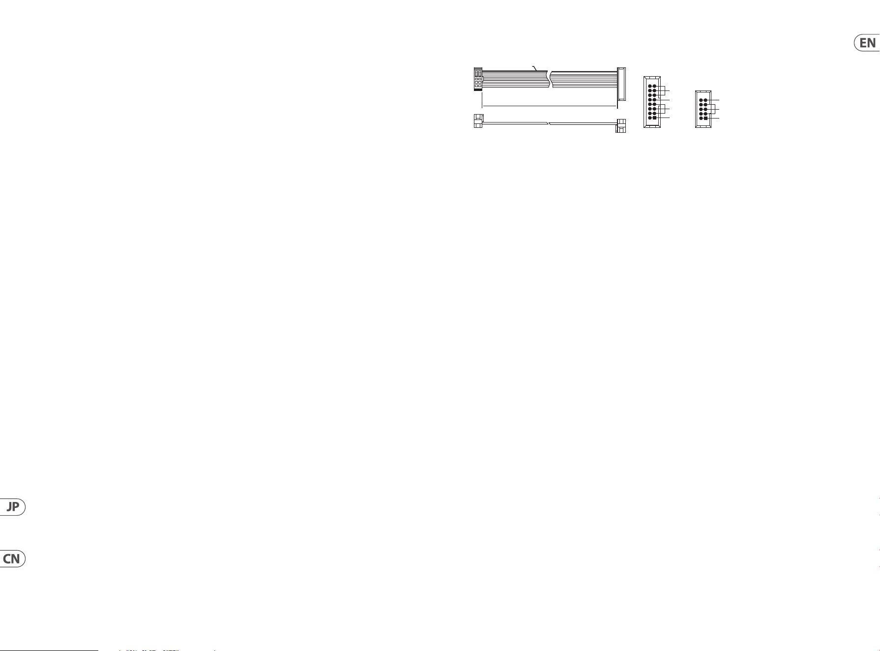
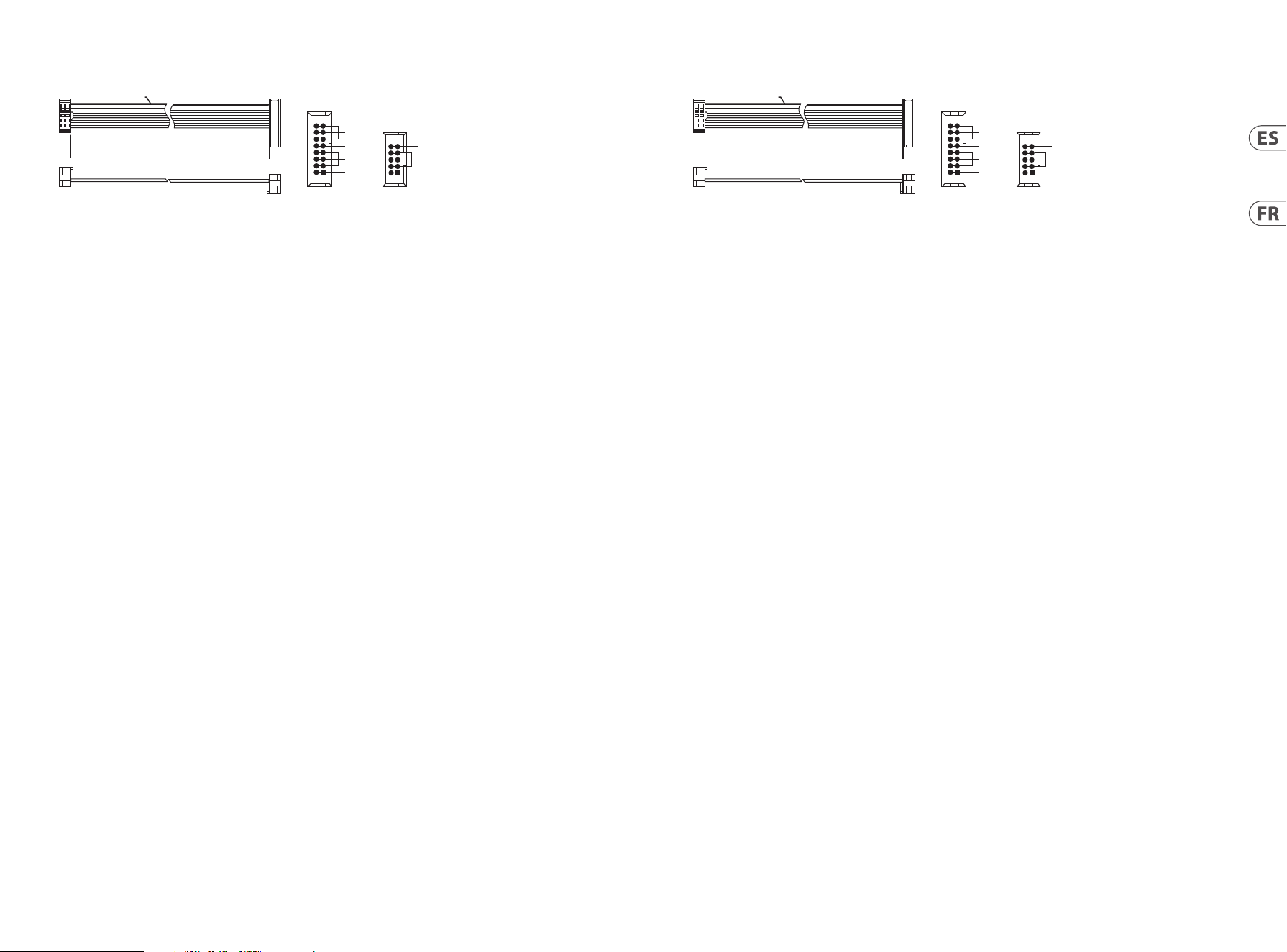
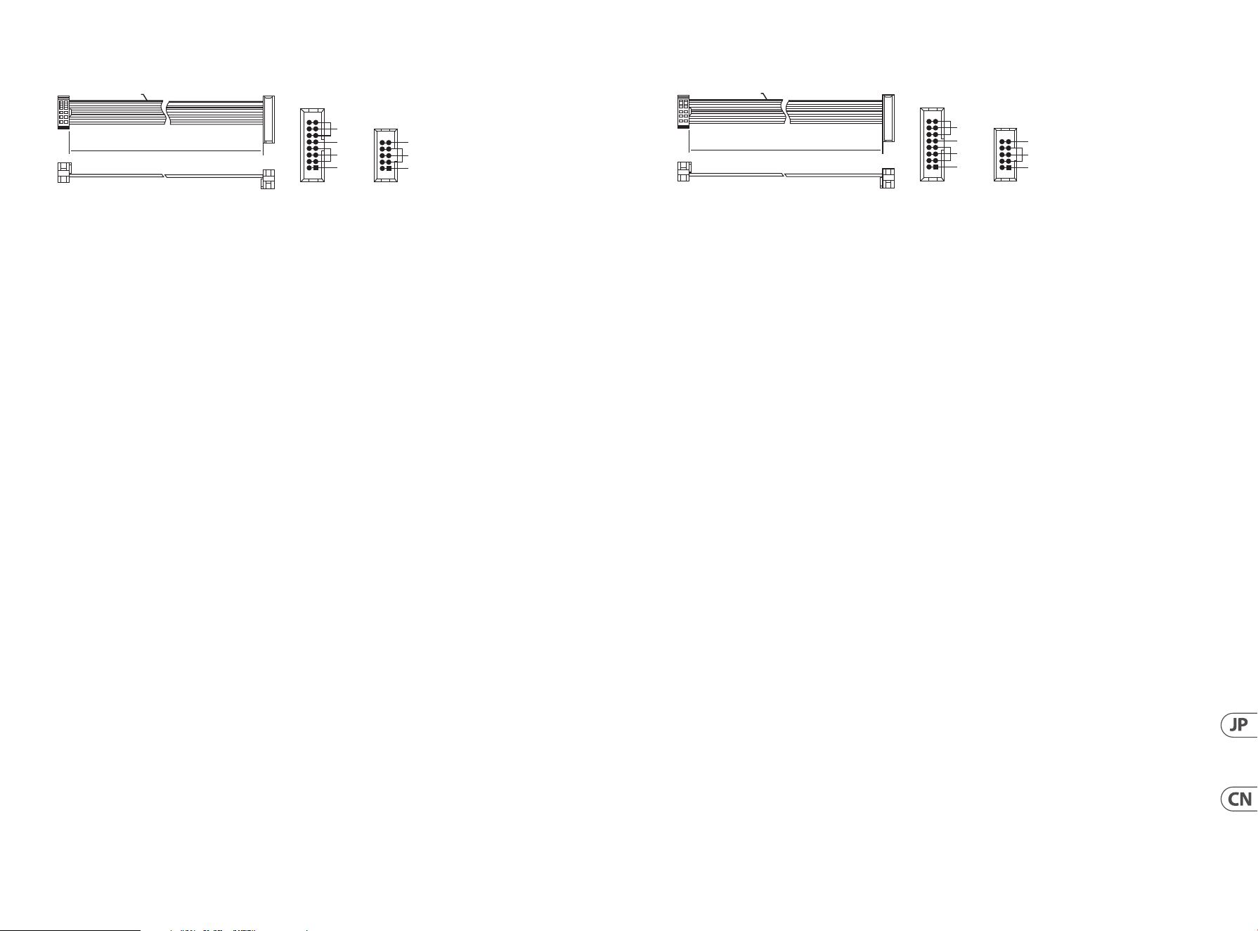
Power Connection
The 130 DUAL VCA comes with the required power cable for connecting to a standard Eurorack power supply system. Follow these steps to
connect power to the module. It is easier to make these connections before the module has been mounted into a rack case.
1. Turn the power supply or rack case power o and disconnect the power cable.
2. Insert the 16-pin connector on the power cable into the socket on the power supply or rack case. The connector has a tab that will
align with the gap in the socket, so it cannot be inserted incorrectly. If the power supply does not have a keyed socket, be sure to
orient pin 1 (-12 V) with the red stripe on the cable.
3. Insert the 10-pin connector into the socket on the back of the module. The connector has a tab that will align with the socket for
correct orientation.
4. After both ends of the power cable have been securely attached, you may mount the module in a case and turn on the power
supply.
Installation
The necessary screws are included with the module for mounting in a Eurorack case. Connect the power cable before mounting.
Depending on the rack case, there may be a series of xed holes spaced 2 HP apart along the length of the case, or a track that allows
individual threaded plates to slide along the length of the case. The free-moving threaded plates allow precise positioning of the module,
but each plate should be positioned in the approximate relation to the mounting holes in your module before attaching the screws.
Hold the module against the Eurorack rails so that each of the mounting holes are aligned with a threaded rail or threaded plate. Attach
the screws part way to start, which will allow small adjustments to the positioning while you get them all aligned. After the nal position
has been established, tighten the screws down.
HOT USED
Red Stripe
200 mm ± 10
15 16
21
P2P1
2
10
9
1
Connect end P1 to the module socket
Connect end P2 to the power supply
+ 12V
- 12V
GROUND
+ 12V
- 12V
GROUND
14 15Quick Start Guide130 DUAL VCA
Conexión Eléctrica
El 130 DUAL VCA viene con el cable de alimentación necesario para conectarse a un sistema de alimentación estándar Eurorack. Siga estos
pasos para conectar la alimentación al módulo. Es más fácil realizar estas conexiones antes de que el módulo se haya montado en una caja
de rack.
1. Apague la fuente de alimentación o la caja del bastidor y desconecte el cable de alimentación.
2. Inserte el conector de 16 clavijas del cable de alimentación en la toma de la fuente de alimentación o en la caja del bastidor. El
conector tiene una pestaña que se alineará con el espacio en el zócalo, por lo que no se puede insertar incorrectamente. Si la fuente
de alimentación no tiene un enchufe con llave, asegúrese de orientar el pin 1 (-12 V) con la raya roja en el cable.
3. Inserte el conector de 10 pines en el zócalo en la parte posterior del módulo. El conector tiene una pestaña que se alineará con el
enchufe para una orientación correcta.
4. Una vez que ambos extremos del cable de alimentación se hayan conectado de forma segura, puede montar el módulo en una caja
y encender la fuente de alimentación.
Instalación
Los tornillos necesarios se incluyen con el módulo para el montaje en una caja Eurorack. Conecte el cable de alimentación antes
delmontaje.
Dependiendo de la caja del bastidor, puede haber una serie de oricios jos separados 2 HP a lo largo de la caja, o una pista que permita
que las placas roscadas individuales se deslicen a lo largo de la caja. Las placas roscadas de movimiento libre permiten un posicionamiento
preciso del módulo, pero cada placa debe colocarse en una relación aproximada con los oricios de montaje en su módulo antes de colocar
los tornillos.
Sostenga el módulo contra los rieles Eurorack de modo que cada uno de los oricios de montaje esté alineado con un riel o placa roscada.
Coloque los tornillos parcialmente para comenzar, lo que permitirá pequeños ajustes en la posición mientras los alinea todos. Una vez
establecida la posición nal, apriete los tornillos.
HOT USED
Red Stripe
200 mm ± 10
15 16
21
P2P1
2
10
9
1
Connect end P1 to the module socket
Connect end P2 to the power supply
+ 12V
- 12V
GROUND
+ 12V
- 12V
GROUND
Connexion Électrique
Le 130 DUAL VCA est livré avec le câble d'alimentation requis pour la connexion à un système d'alimentation standard Eurorack. Suivez ces
étapes pour connecter l'alimentation au module. Il est plus facile d'eectuer ces connexions avant que le module n'ait été monté dans un
boîtier de rack.
1. Mettez le bloc d'alimentation ou le boîtier de rack hors tension et débranchez le câble d'alimentation.
2. Insérez le connecteur à 16 broches du câble d'alimentation dans la prise du bloc d'alimentation ou du boîtier du rack. Le connecteur
a une languette qui s'alignera avec l'espace dans la prise, de sorte qu'il ne peut pas être inséré de manière incorrecte. Si le bloc
d'alimentation n'a pas de prise à clé, veillez à orienter la broche 1 (-12 V) avec la bande rouge sur le câble.
3. Insérez le connecteur à 10 broches dans la prise à l'arrière du module. Le connecteur a une languette qui s'alignera avec la prise
pour une orientation correcte.
4. Une fois que les deux extrémités du câble d'alimentation ont été solidement xées, vous pouvez monter le module dans un boîtier
et allumer l'alimentation.
Installation
Les vis nécessaires sont incluses avec le module pour le montage dans un boîtier Eurorack. Connectez le câble d'alimentation avant le
montage.
Selon le cas de rack, il peut y avoir une série de trous xes espacés de 2 HP sur la longueur du cas, ou une piste qui permet aux plaques
letées individuelles de glisser le long de la longueur du cas. Les plaques letées à déplacement libre permettent un positionnement
précis du module, mais chaque plaque doit être positionnée approximativement par rapport aux trous de montage de votre module avant
de xer les vis.
Maintenez le module contre les rails Eurorack de sorte que chacun des trous de montage soit aligné avec un rail leté ou une plaque
letée. Fixez les vis partiellement pour commencer, ce qui permettra de petits ajustements au positionnement pendant que vous les
alignerez tous. Une fois la position nale établie, serrez les vis vers le bas.
HOT USED
Red Stripe
200 mm ± 10
15 16
21
P2P1
2
10
9
1
Connect end P1 to the module socket
Connect end P2 to the power supply
+ 12V
- 12V
GROUND
+ 12V
- 12V
GROUND
16 17Quick Start Guide130 DUAL VCA
Netzanschluss
Der 130 DUAL VCA wird mit dem erforderlichen Stromkabel für den Anschluss an ein Standard-Eurorack-Stromversorgungssystem
geliefert. Befolgen Sie diese Schritte, um das Modul mit Strom zu versorgen. Es ist einfacher, diese Verbindungen herzustellen, bevor das
Modul in ein Rackgehäuse eingebaut wurde.
1. Schalten Sie das Netzteil oder das Rackgehäuse aus und ziehen Sie das Netzkabel ab.
2. Stecken Sie den 16-poligen Stecker am Netzkabel in die Buchse am Netzteil oder im Rack-Gehäuse. Der Anschluss verfügt über eine
Lasche, die an der Lücke in der Buchse ausgerichtet ist, sodass sie nicht falsch eingesetzt werden kann. Wenn das Netzteil keine
Schlüsselbuchse hat, achten Sie darauf, Pin 1 (-12 V) mit dem roten Streifen am Kabelauszurichten.
3. Stecken Sie den 10-poligen Stecker in die Buchse auf der Rückseite des Moduls. Der Anschluss verfügt über eine Lasche, die zur
korrekten Ausrichtung an der Buchse ausgerichtet wird.
4. Nachdem beide Enden des Netzkabels fest angeschlossen wurden, können Sie das Modul in einem Gehäuse montieren und die
Stromversorgung einschalten.
Installation
Die erforderlichen Schrauben sind im Lieferumfang des Moduls für die Montage in einem Eurorack-Gehäuse enthalten. Schließen Sie das
Netzkabel vor der Montage an.
Abhängig vom Rack-Gehäuse kann es eine Reihe von festen Löchern geben, die entlang der Länge des Gehäuses 2 PS voneinander
entfernt sind, oder eine Schiene, mit der einzelne Gewindeplatten entlang der Länge des Gehäuses gleiten können. Die frei beweglichen
Gewindeplatten ermöglichen eine präzise Positionierung des Moduls. Jede Platte sollte jedoch in der ungefähren Beziehung zu den
Befestigungslöchern in Ihrem Modul positioniert werden, bevor Sie die Schrauben anbringen.
Halten Sie das Modul so gegen die Eurorack-Schienen, dass jedes der Befestigungslöcher mit einer Gewindeschiene oder einer
Gewindeplatte ausgerichtet ist. Bringen Sie die Schrauben teilweise an, um zu beginnen. Dadurch können Sie die Position geringfügig
anpassen, während Sie alle ausrichten. Ziehen Sie die Schrauben fest, nachdem die endgültige Position festgelegtwurde.
HOT USED
Red Stripe
200 mm ± 10
15 16
21
P2P1
2
10
9
1
Connect end P1 to the module socket
Connect end P2 to the power supply
+ 12V
- 12V
GROUND
+ 12V
- 12V
GROUND
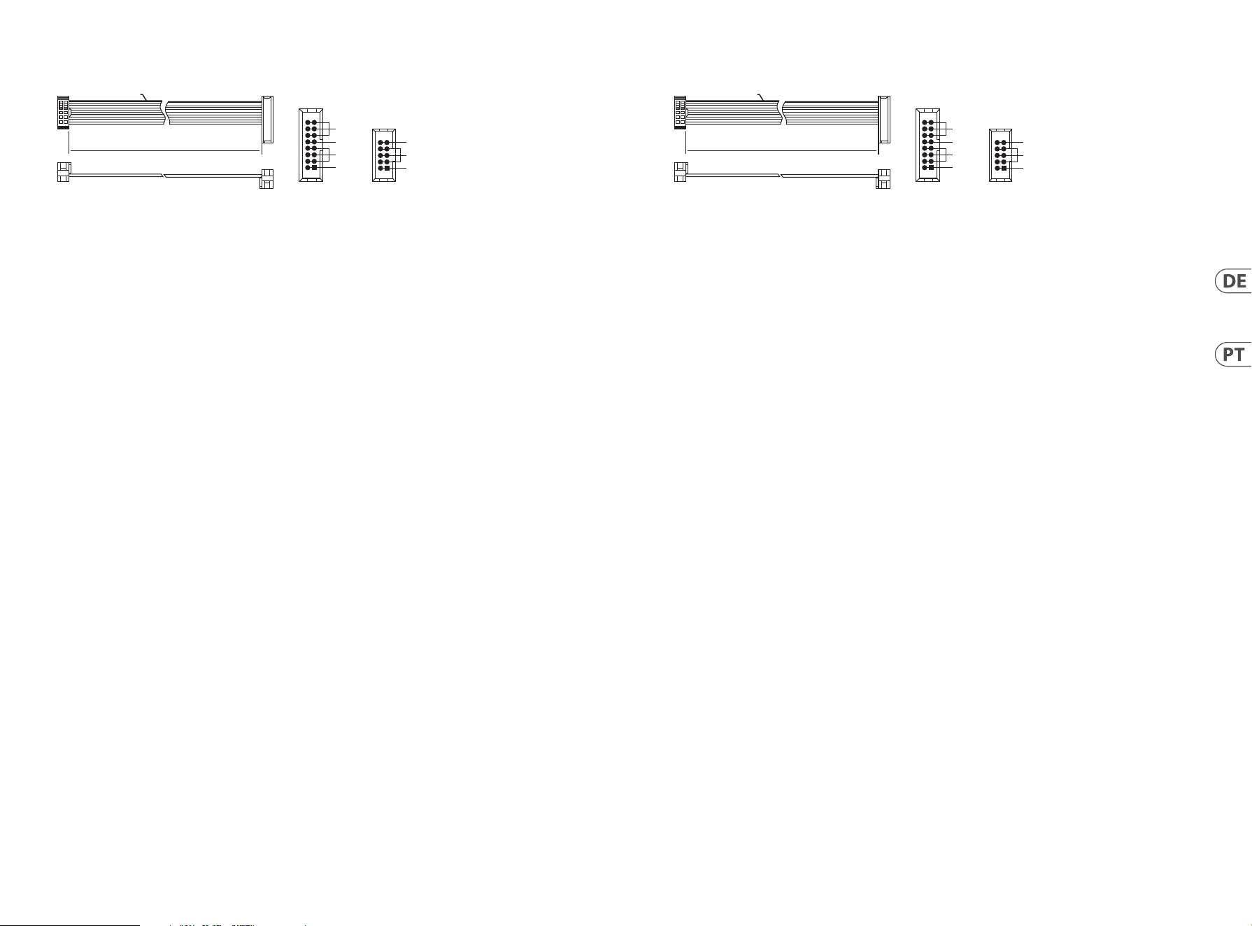
Conexão de Força
O 130 DUAL VCA vem com o cabo de alimentação necessário para conectar a um sistema de fonte de alimentação Eurorack padrão. Siga
estas etapas para conectar a alimentação ao módulo. É mais fácil fazer essas conexões antes que o módulo seja montado em um gabinete
de rack.
1. Desligue a fonte de alimentação ou o gabinete do rack e desconecte o cabo de alimentação.
2. Insira o conector de 16 pinos do cabo de alimentação no soquete da fonte de alimentação ou no gabinete do rack. O conector possui
uma aba que se alinhará com a lacuna no soquete, portanto, não pode ser inserido incorretamente. Se a fonte de alimentação não
tiver um soquete chaveado, certique-se de orientar o pino 1 (-12 V) com a faixa vermelha no cabo.
3. Insira o conector de 10 pinos no soquete na parte traseira do módulo. O conector possui uma guia que se alinha ao soquete para
orientação correta.
4. Depois que ambas as extremidades do cabo de alimentação forem conectadas com segurança, você pode montar o módulo em
uma caixa e ligar a fonte de alimentação.
Instalação
Os parafusos necessários estão incluídos com o módulo para montagem em uma caixa Eurorack. Conecte o cabo de alimentação antes da
montagem.
Dependendo da caixa do rack, pode haver uma série de orifícios xos espaçados de 2 HP ao longo do comprimento da caixa, ou um
trilho que permite que placas roscadas individuais deslizem ao longo do comprimento da caixa. As placas roscadas de movimento livre
permitem o posicionamento preciso do módulo, mas cada placa deve ser posicionada em uma relação aproximada com os orifícios de
montagem em seu módulo antes de prender osparafusos.
Segure o módulo contra os trilhos Eurorack de forma que cada um dos orifícios de montagem quem alinhados com um trilho ou placa
rosqueada. Prenda os parafusos parcialmente para começar, o que permitirá pequenos ajustes no posicionamento enquanto você os
alinha. Depois de estabelecida a posição nal, aperte osparafusos.
HOT USED
Red Stripe
200 mm ± 10
15 16
21
P2P1
2
10
9
1
Connect end P1 to the module socket
Connect end P2 to the power supply
+ 12V
- 12V
GROUND
+ 12V
- 12V
GROUND
18 19Quick Start Guide130 DUAL VCA
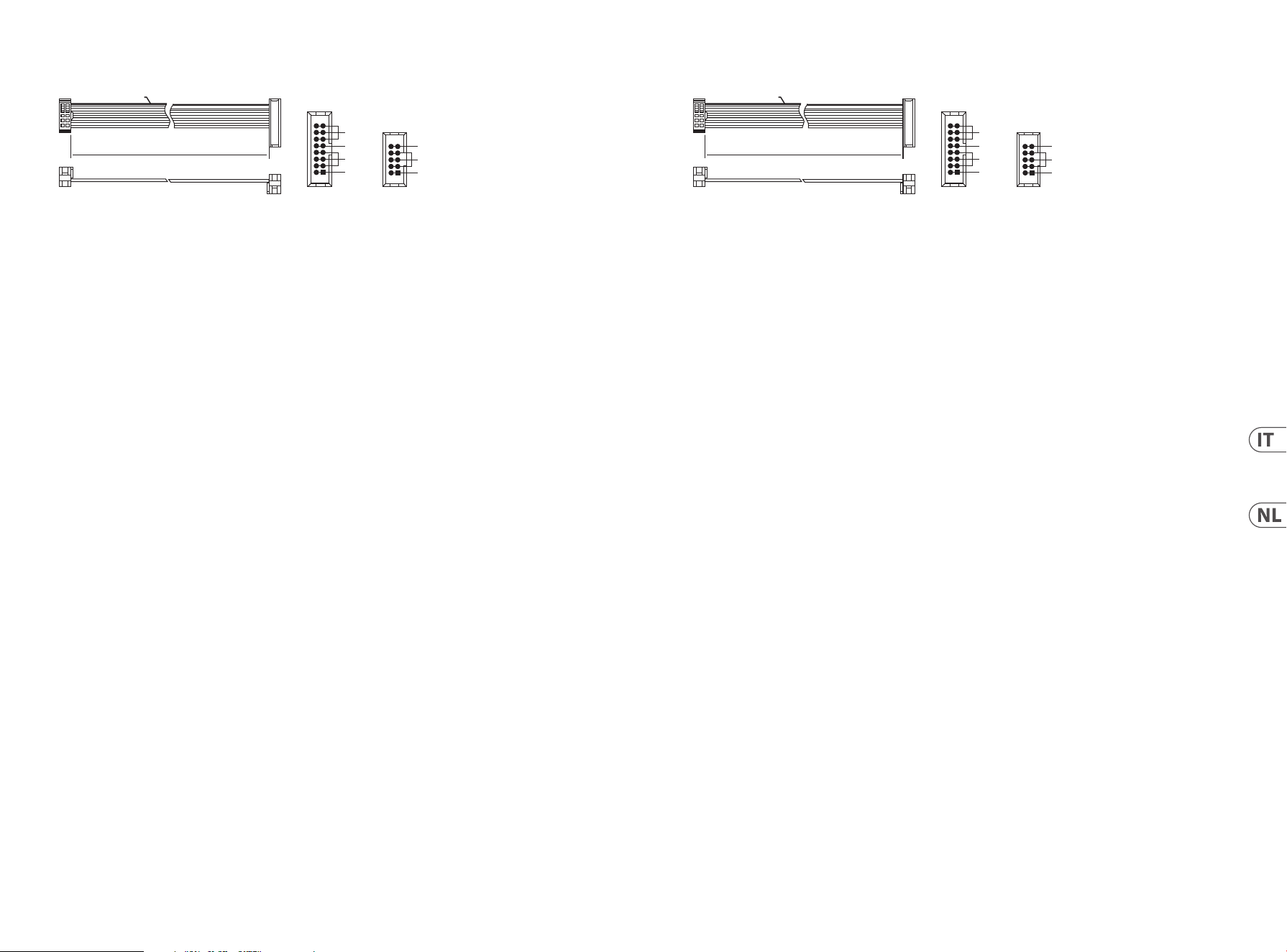
Connessione di Alimentazione
Il 130 DUAL VCA viene fornito con il cavo di alimentazione necessario per il collegamento a un sistema di alimentazione Eurorack
standard. Seguire questi passaggi per collegare l'alimentazione al modulo. È più facile eettuare questi collegamenti prima che il modulo
sia stato montato in un caserack.
1. Spegnere l'alimentatore o il case del rack e scollegare il cavo di alimentazione.
2. Inserire il connettore a 16 pin del cavo di alimentazione nella presa sull'alimentatore o sul case del rack. Il connettore ha una
linguetta che si allineerà con lo spazio nella presa, quindi non può essere inserito in modo errato. Se l'alimentatore non dispone di
una presa con chiave, assicurarsi di orientare il pin 1 (-12 V) con la striscia rossa sul cavo.
3. Inserire il connettore a 10 pin nella presa sul retro del modulo. Il connettore ha una linguetta che si allineerà con la presa per un
corretto orientamento.
4. Dopo che entrambe le estremità del cavo di alimentazione sono state ssate saldamente, è possibile montare il modulo in una
custodia e accendere l'alimentatore.
Installazione
Le viti necessarie sono incluse con il modulo per il montaggio in una custodia Eurorack. Collegare il cavo di alimentazione prima
delmontaggio.
A seconda del case del rack, potrebbero esserci una serie di fori ssi distanziati di 2 HP l'uno dall'altro lungo la lunghezza del case, o
un binario che consente alle singole piastre lettate di scorrere lungo la lunghezza del case. Le piastre lettate a movimento libero
consentono un posizionamento preciso del modulo, ma ciascuna piastra deve essere posizionata in relazione approssimativa con i fori di
montaggio nel modulo prima di ssarele viti.
Tenere il modulo contro le guide Eurorack in modo che ciascuno dei fori di montaggio sia allineato con una guida lettata o una piastra
lettata. Attaccare le viti in parte per iniziare, il che consentirà piccoli aggiustamenti al posizionamento mentre le si allineano tutte. Dopo
aver stabilito la posizione nale, serrareleviti.
HOT USED
Red Stripe
200 mm ± 10
15 16
21
P2P1
2
10
9
1
Connect end P1 to the module socket
Connect end P2 to the power supply
+ 12V
- 12V
GROUND
+ 12V
- 12V
GROUND
Stroomaansluiting
De 130 DUAL VCA wordt geleverd met de benodigde voedingskabel voor aansluiting op een standaard Eurorack-voedingssysteem.
Volg deze stappen om de module van stroom te voorzien. Het is gemakkelijker om deze aansluitingen te maken voordat de module
in een rekbehuizing is gemonteerd.
1. Schakel de voeding of de rekbehuizing uit en koppel de voedingskabel los.
2. Steek de 16-pins connector van de voedingskabel in de aansluiting op de voedingseenheid of rekbehuizing. De connector heeft
een lipje dat wordt uitgelijnd met de opening in de socket, zodat deze niet verkeerd kan worden geplaatst. Als de voeding geen
contactdoos met sleutel heeft, zorg er dan voor dat pin 1 (-12 V) met de rode streep op de kabel wordt georiënteerd.
3. Steek de 10-pins connector in de aansluiting aan de achterkant van de module. De connector heeft een lipje dat uitgelijnd is met
de aansluiting voor de juiste oriëntatie.
4. Nadat beide uiteinden van de voedingskabel stevig zijn bevestigd, kunt u de module in een hoesje monteren en de
voedinginschakelen.
Installatie
De benodigde schroeven worden bij de module geleverd voor montage in een Eurorack-koer. Sluit de voedingskabel aan voormontage.
Afhankelijk van de rackbehuizing kan er een reeks vaste gaten zijn die 2 HP uit elkaar liggen over de lengte van de behuizing, of een
rail waarmee afzonderlijke platen met schroefdraad langs de lengte van de behuizing kunnen schuiven. De vrij bewegende plaatjes
met schroefdraad maken een nauwkeurige positionering van de module mogelijk, maar elke plaat moet ongeveer in verhouding tot de
montagegaten in uw module worden geplaatst voordat u de schroeven bevestigt.
Houd de module tegen de Eurorack-rails zodat elk van de montagegaten is uitgelijnd met een rail met schroefdraad of een plaat met
schroefdraad. Bevestig de schroeven halverwege om te beginnen, waardoor kleine aanpassingen aan de positionering mogelijk zijn
terwijl u ze allemaal op één lijn krijgt. Nadat de denitieve positie is bepaald, draait u de schroeven vast.
HOT USED
Red Stripe
200 mm ± 10
15 16
21
P2P1
2
10
9
1
Connect end P1 to the module socket
Connect end P2 to the power supply
+ 12V
- 12V
GROUND
+ 12V
- 12V
GROUND
20 21Quick Start Guide130 DUAL VCA
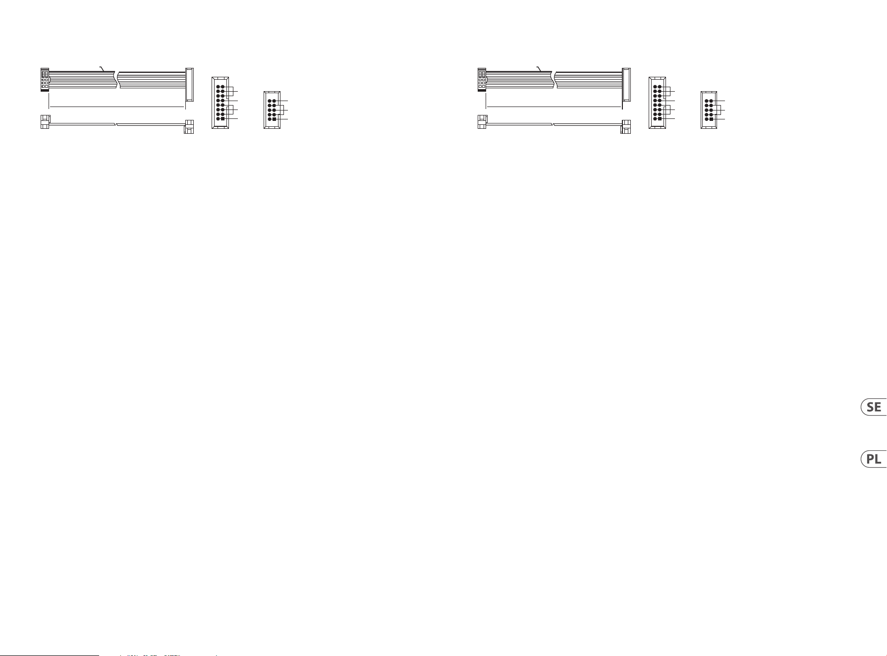
Strömanslutning
130 DUAL VCA levereras med den nödvändiga strömkabeln för anslutning till ett vanligt Eurorack-nätaggregat. Följ dessa steg för att
ansluta ström till modulen. Det är lättare att göra dessa anslutningar innan modulen har monterats i ett rackfodral.
1. Stäng av strömmen eller rackhöljet och koppla bortströmkabeln.
2. Sätt i den 16-poliga kontakten på strömkabeln i uttaget på strömförsörjningen eller rackfodralet. Kontaktdonet har en ik som
kommer i linje med springan i uttaget, så att den inte kan sättas in på fel sätt. Om strömförsörjningen inte har ett nyckeluttag, se
till att orientera stift 1 (-12 V) med den röda remsan på kabeln.
3. Sätt i 10-polig kontakt i uttaget på modulens baksida. Kontaktdonet har en ik som kommer i linje med uttaget för korrekt
orientering.
4. När båda ändarna av strömkabeln har anslutits ordentligt kan du montera modulen i ett fodral och slå påströmförsörjningen.
Installation
De nödvändiga skruvarna ingår i modulen för montering i ett Eurorack-fodral. Anslut strömkabeln före montering.
Beroende på stativhöljet kan det nnas en serie fasta hål som är åtskilda 2 hk längs höljets längd eller ett spår som gör att enskilda
gängade plattor kan glida längs höljets längd. De fritt rörliga gängade plattorna möjliggör exakt positionering av modulen, men varje
platta bör placeras i ungefärlig relation till monteringshålen i din modul innan skruvarna fästs.
Håll modulen mot Eurorack-skenorna så att var och en av monteringshålen är inriktade mot en gängad skena eller gängad platta.
Fästskruvarna delvis för att börja, vilket möjliggör små justeringar av positioneringen medan du justerar dem alla. När den slutliga
positionen har fastställts drar du åt skruvarna.
HOT USED
Red Stripe
200 mm ± 10
15 16
21
P2P1
2
10
9
1
Connect end P1 to the module socket
Connect end P2 to the power supply
+ 12V
- 12V
GROUND
+ 12V
- 12V
GROUND
Podłączenie Zasilania
130 DUAL VCA jest dostarczany z wymaganym kablem zasilającym do podłączenia do standardowego systemu zasilania Eurorack.
Wykonaj poniższe czynności, aby podłączyć zasilanie do modułu. Łatwiej jest wykonać te połączenia przed zamontowaniem modułu w
obudowie rack.
1. Wyłącz zasilacz lub obudowę szafy i odłącz kabel zasilający.
2. Włóż 16-stykowe złącze przewodu zasilającego do gniazda w zasilaczu lub w szae typu Rack. Złącze ma wypustkę, która będzie
wyrównana ze szczeliną w gnieździe, więc nie można jej nieprawidłowo włożyć. Jeśli zasilacz nie ma gniazda z kluczem, należy
zorientować styk 1 (-12 V) z czerwonym paskiem na kablu.
3. Włóż 10-pinowe złącze do gniazda z tyłu modułu. Złącze ma wypustkę, która będzie wyrównana z gniazdem, aby zapewnić
prawidłową orientację.
4. Po solidnym zamocowaniu obu końców kabla zasilającego można zamontować moduł w obudowie i włączyć zasilacz.
Instalacja
Do modułu dołączone są niezbędne śruby do montażu w skrzynce Eurorack. Podłącz kabel zasilający przed montażem.
W zależności od obudowy szafy może występować szereg stałych otworów rozmieszczonych w odstępach 2 HP na całej długości
obudowy lub prowadnica, która umożliwia przesuwanie pojedynczych gwintowanych płyt wzdłuż całej obudowy. Swobodnie
poruszające się gwintowane płytki umożliwiają precyzyjne ustawienie modułu, ale każda płyta powinna być ustawiona w przybliżeniu w
stosunku do otworów montażowych w module przed przykręceniem śrub.
Przytrzymaj moduł na szynach Eurorack, tak aby każdy z otworów montażowych był wyrównany z szyną gwintowaną lub płytą
gwintowaną. Wkręć śruby częściowo, aby rozpocząć, co pozwoli na drobne korekty położenia, gdy wszystkie zostaną wyrównane. Po
ustaleniu ostatecznego położenia dokręcić śruby.
HOT USED
Red Stripe
200 mm ± 10
15 16
21
P2P1
2
10
9
1
Connect end P1 to the module socket
Connect end P2 to the power supply
+ 12V
- 12V
GROUND
+ 12V
- 12V
GROUND
22 23Quick Start Guide130 DUAL VCA
電源接続
130 DUAL VCA に は 、標 準 の Eurorack 電源システムに接続するために必要な電源ケーブルが付属しています。次の手順
に従って、モジュールに電源を接続します。モジュールをラックケースに取り付ける前に、これらの接続を行う方が
簡 単で す。
1. 電源装置またはラックケースの電源を切り、電源ケーブルを外します。
2. 電 源 ケーブル の 16 ピンコネクタを電源装置またはラックケースのソケットに挿入します。コネクタにはソケッ
トの隙間に合うタブが 付いているので、間違って挿入することはできません。電源装置にキー 付きソケットが
な い 場 合 は 、必 ず ピ ン 1(-12 V) を ケ ーブル の 赤 い ストラ イプ に向 け てくだ さい 。
3. モジュールの背面にあるソケットに 10 ピンコネクタを挿入します。コネクタには、正しい方向に向けてソケット
と位 置 合 わ せ するタブ が ありま す。
4. 電源ケーブルの両端をしっかりと取り付けたら、モジュールをケースに取り付けて電源を入れ
ます。
インストール
必要なネジは、ユーロラックケースに取り付けるためのモジュールに含まれています。取り付ける前に電源ケーブル
を接 続してくだ さい 。
ラックケ ース に よっては 、ケースの 長さに 沿 って 2 HP 間隔で配置された一連の固定穴、または個々のネジ付きプレー
トをケースの長さに沿ってスライドできるトラックが存在する場 合があります。自由に動くネジ付きプレートにより、
モジュール を正確に配置できますが、ネジ を取り付ける前に、各プレートをモジュール の取り付け穴とほぼ 同じ位置
に配 置する 必 要 が あります。
モジュールをユーロラックレールに押し付けて、各取り付け穴がネジ付きレールまたはネジ付きプレートと揃うよう
にします。開 始 の 途 中 でネジ を 取り付けます。これ により、すべ てのネジ を 揃 え ながら、位 置を 微 調 整 できま す。最
終位置が決まったら、ネジを締めます。
HOT USED
Red Stripe
200 mm ± 10
15 16
21
P2P1
2
10
9
1
Connect end P1 to the module socket
Connect end P2 to the power supply
+ 12V
- 12V
GROUND
+ 12V
- 12V
GROUND
电源连接
130 DUAL VCA 随附所需的电源线, 用于连接到标准 Eurorack 电源系统。请按照以下步骤将电源连接到模块。在将模块安
装到机架盒中之前, 进行这些连接会更容易。
1. 关闭电源或机架式机箱的电源, 然后断开电源线的连接。
2. 将电源线上的 16 针连接器插入电源或机架盒上的插座。该连接器具有一个卡舌, 该卡舌将与插槽中的间隙
对齐, 因此不会被错误地插入。如果电源没有键控插座, 请确保将插针 1(-12 V) 的方向与电缆上的红色条纹对准。
3. 将 10 针连接器插入模块背面的插槽中。连接器具有一个卡舌, 该卡舌将与插座对齐以正确定向。
4. 在牢固连接电源线的两端之后, 您可以将模块安装在盒中并打开电源。
安装
模块随附了必 要 的螺钉, 用于将其安装在 Eurorack 箱中。安装前, 请先连接电源线。
根据机架机箱的不同, 可能会有一系列沿机箱长度方向相距 2 HP 的固定孔, 或者是一条允许单个螺纹板沿机箱长度
方向滑动的导轨。可以自由移动的螺纹板可以精确定位模块, 但是在安装螺钉之前, 应将每个板的位置与模块上的安
装孔大致成一定关系。
将模块靠在 Eurorack 导轨上, 以使每个安装孔都与螺纹导轨或螺纹板对齐。从头开始固定螺丝,
在对齐时可以对位置进行细微调整。确定最终位置后, 拧紧螺钉。
HOT USED
Red Stripe
200 mm ± 10
15 16
21
P2P1
2
10
9
1
Connect end P1 to the module socket
Connect end P2 to the power supply
+ 12V
- 12V
GROUND
+ 12V
- 12V
GROUND
24 25Quick Start Guide130 DUAL VCA
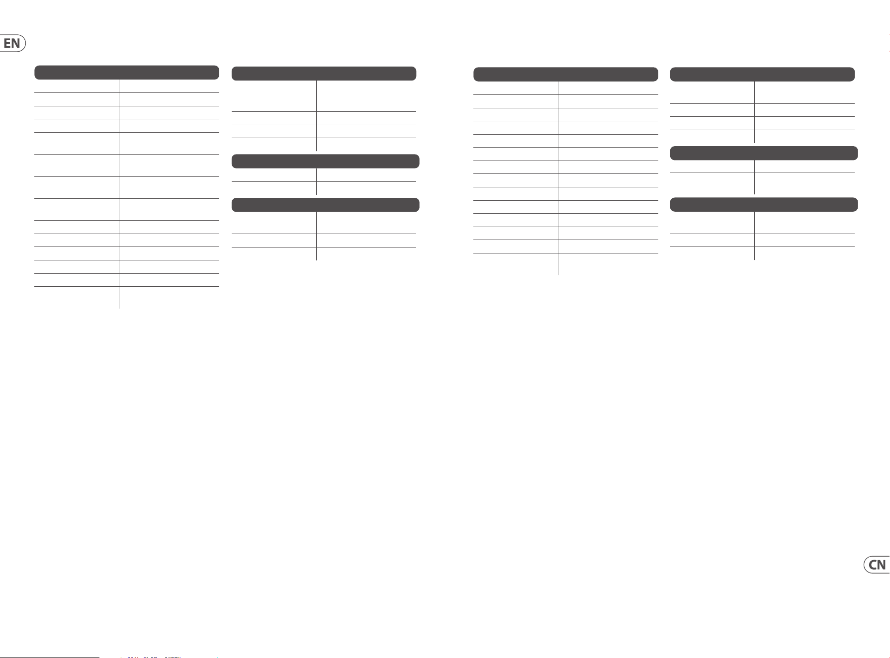
Specications
Signal Connections
Signal in 6 x 3.5 mm jack, summed
Impedance > 50 kΩ unbalanced
Maximum input level +18 dBu @ unity gain
VCA out high / low 4 x 3.5 mm jack
High output
Impedance
1 kΩ unbalanced
Low output
Impedance
3 kΩ unbalanced
High maximum
output level
+18 dBu
Low maximum
output level
-2 dBu
High output noise < -66 dBu, 22 Hz - 22 kHz
Low output noise < -86 dBu, 22 Hz - 22 kHz
Mod in 6 x 3.5 mm jack
Impedance > 50 kΩ unbalanced
CV input range 0 V to +10 V
CV scaling in
EXP mode
Typically 1 V/10 dB
Controls
Initial gain
2 x rotary knob
Linear / exponential,
switchable
Sig in level 6 x rotary knob
Mod in level 6 x rotary knob
Linear / exponential CV 2 x sliding switch
Power
Power supply Eurorack
Current draw 30 mA (+12 V), 20 mA (-12 V)
Physical
Dimensions (H x W x D)
44 x 81 x 129 mm
(1.7 x 3.2 x 5.1")
Rack units 16 HP
Weight 0.18 kg (0.4 lbs)
技术参数
信号连接
信号输入
总计 6 x 3.5 mm 插孔
阻抗
> 50 kΩ 不平衡
最大输入电平
+18 dBu @ 单位增益
VCA 输出高 / 低 4 x 3.5 mm 插孔
高输出阻抗
1 kΩ 不平衡
低输出阻抗
3 kΩ 不平衡
高最大输出电平
+18 dBu
最大输出水平低
-2 dBu
高输出噪音
< -66 dBu, 22 Hz -22 kHz
低输出噪音
< -86 dBu, 22 Hz -22 kHz
修改中
6 x 3.5 mm 插孔
阻抗
> 50 kΩ 不平衡
恒压输入范围
0 V to +10 V
EXP 模式下的 CV
缩放
通常为 1 V/10 dB
控制项
初始收益
2 个旋钮线性 /
指数型, 可切换
信号等级
6 x 旋钮
模组水平
6 x 旋钮
线性 / 指数简历 2 个滑动开关
力量
电源供应 欧陆架
电流消耗
30 mA (+12 V),
20 mA (-12 V)
身体的
尺寸 (H x W x D)
44 x 81 x 129 mm
(1.7 x 3.2 x 5.1")
机架单位
16 HP
重量
0.18 kg (0.4 lbs)
26 27Quick Start Guide130 DUAL VCA
FEDERAL COMMUNICATIONS
COMMISSION COMPLIANCE
INFORMATION
Behringer
130 DUAL VCA
Responsible Party Name: Music Tribe Commercial NV Inc.
Address: 122 E. 42nd St.1,
8th Floor NY, NY 10168,
United States
Email Address: [email protected]
130 DUAL VCA
This equipment has been tested and found to comply with the
limits for a Class B digital device, pursuant to part 15 of the FCC
Rules. These limits are designed to provide reasonable protection
against harmful interference in a residential installation. This
equipment generates, uses and can radiate radio frequency energy
and, if not installed and used in accordance with the instructions,
may cause harmful interference to radio communications. However,
there is no guarantee that interference will not occur in a particular
installation. If this equipment does cause harmful interference to
radio or television reception, which can be determined by turning
the equipment o and on, the user is encouraged to try to correct
the interference by one or more of the following measures:
• • Reorient or relocate the receiving antenna.
• • Increase the separation between the equipment and receiver.
• • Connect the equipment into an outlet on a circuit dierent from
that to which the receiver is connected.
• • Consult the dealer or an experienced radio/TV technician
forhelp.
This equipment complies with Part 15 of the FCC rules. Operation is
subject to the following two conditions:
(1) this device may not cause harmful interference, and
(2) this device must accept any interference received, including
interference that may cause undesired operation.
Important information:
Changes or modications to the equipment not expressly approved
by Music Tribe can void the user’s authority to use theequipment.
Hereby, Music Tribe declares that this product is in compliance
with Directive 2014/30/EU, Directive 2011/65/EU and Amendment
2015/863/EU, Directive 2012/19/EU, Regulation 519/2012 REACH
SVHC and Directive 1907/2006/EC.
Full text of EU DoC is available at https://community.musictribe.com/
EU Representative: Music Tribe Brands DK A/S
Address: Gammel Strand 44, DK-1202 København K, Denmark
UK Representative: Music Tribe Brands UK Ltd.
Address: 8
th
Floor, 20 Farringdon Street London EC4A 4AB,
United Kingdom
Correct disposal of this product: This symbol
indicates that this product must not be disposed
of with household waste, according to the WEEE
Directive (2012/19/EU) and your national law. This
product should be taken to a collection center
licensed for the recycling of waste electrical and
electronic equipment (EEE). The mishandling of
this type of waste could have a possible negative impact on the
environment and human health due to potentially hazardous
substances that are generally associated with EEE. At the same
time, your cooperation in the correct disposal of this product
will contribute to the ecient use of natural resources. For more
information about where you can take your waste equipment for
recycling, please contact your local city oce, or your household
waste collection service.
型 号: 130 DUAL VCA 合成器与采样器
制造商: Empower Tribe Commercial FZE –
Made in China 中国制造
CAN ICES–003 (B)/NMB–003 (B)

We Hear You