User Manual
Automatic Bollard
Applicable Model: BOL1219-A
Version: 1.0
Date: 11/2018

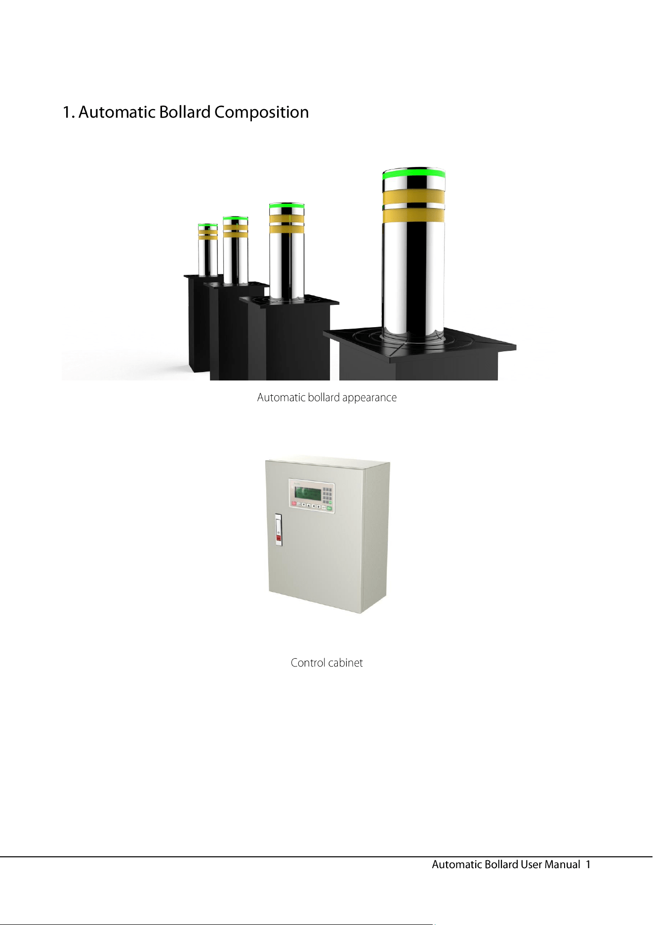
1. Automatic Bollard Composition ....................................................................................................................1
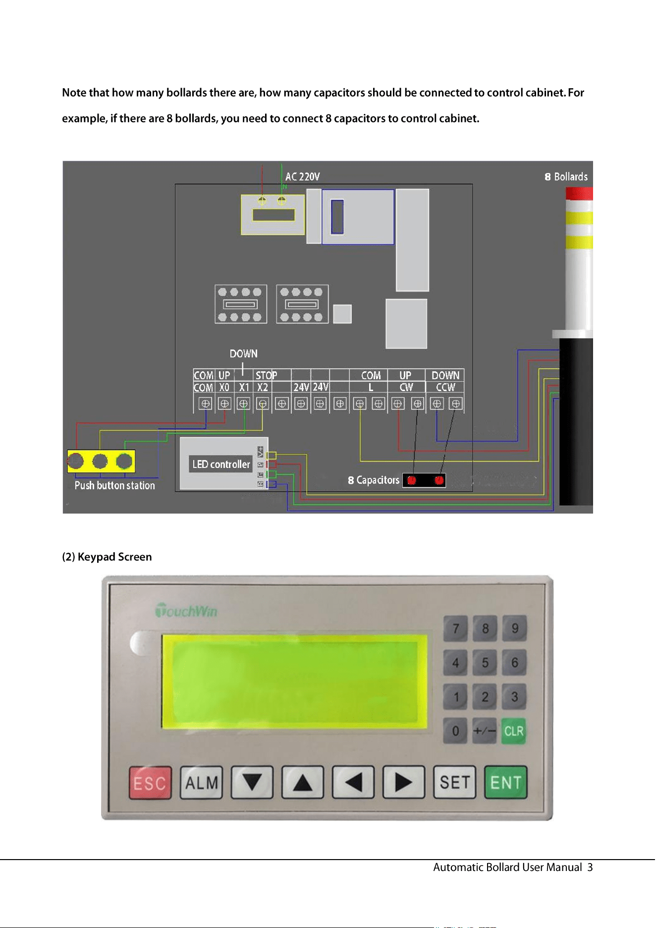
2. Control Cabinet ............................................................................................................................................2
3. Installation and Usage Procedures ..............................................................................................................4
4. Precautions...................................................................................................................................................6
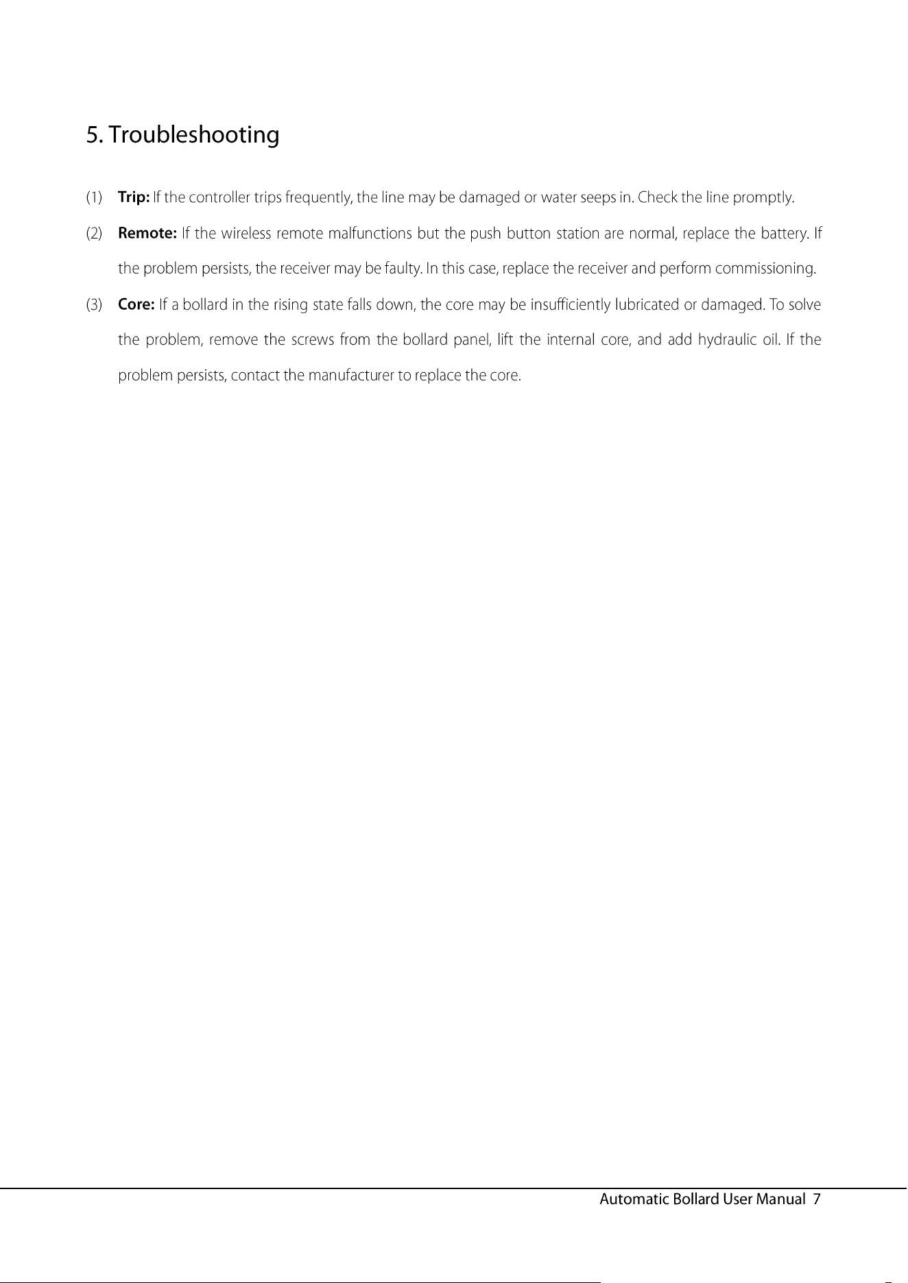
5. Troubleshooting ............................................................................................................................................7
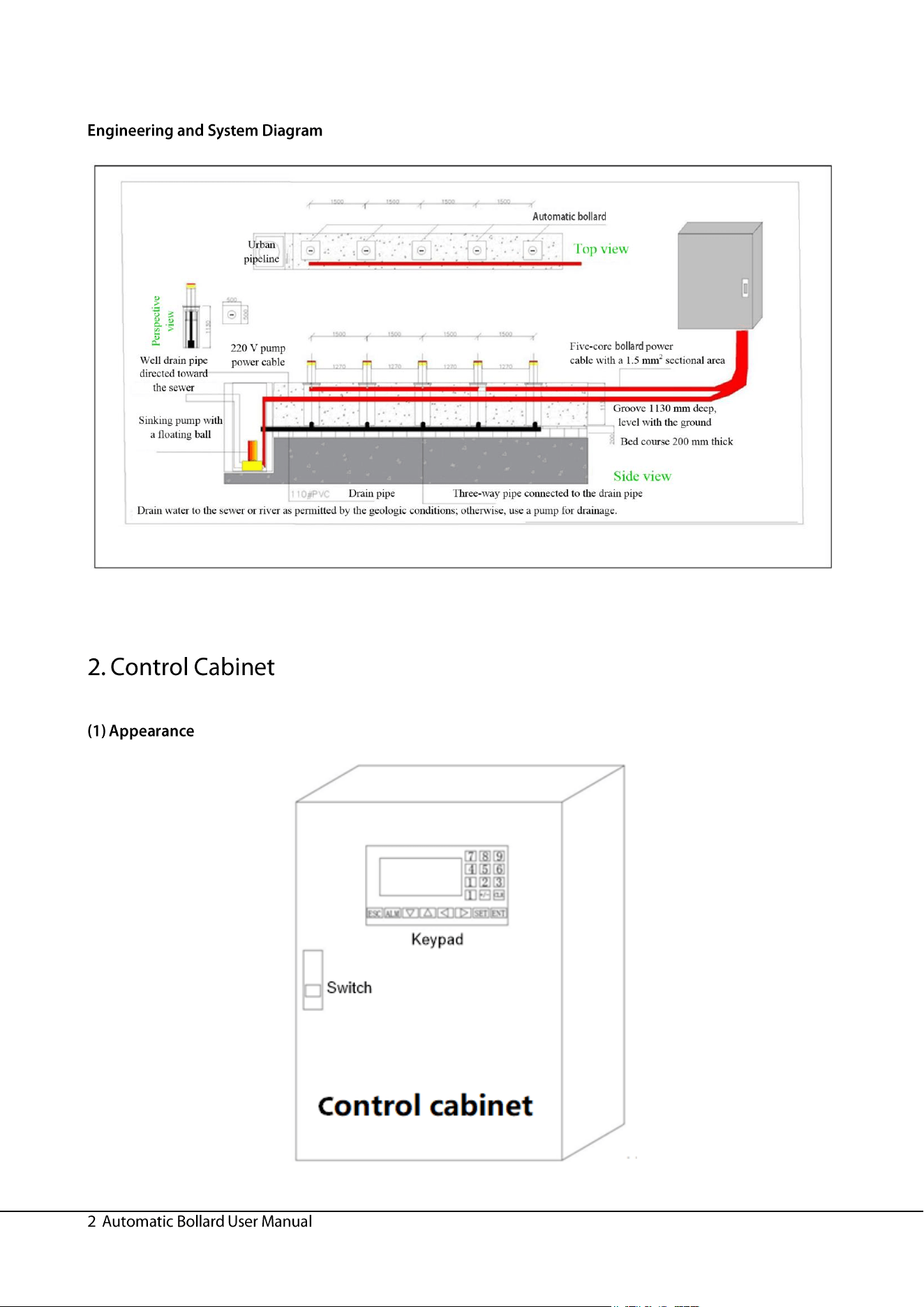
Automatic integrated hydraulic lifting column
Urban
pipeline
Top view
Perspective
view
220 V pump
power cable
Well drain pipe
directed toward
the sewer
Sinking pump with
a floating ball
Five-core lifting column power
cable with a 1.5 mm
2
sectional area
Groove 1130 mm deep,
level with the ground
Bed course 200 mm thick
Drain pipe Three-way pipe connected to the drain pipe
Side view
Drain water to the sewer or river as permitted by the geologic conditions; otherwise, use a pump for drainage.
External Internal
Rise
Stop
Fall
Public
terminal
①
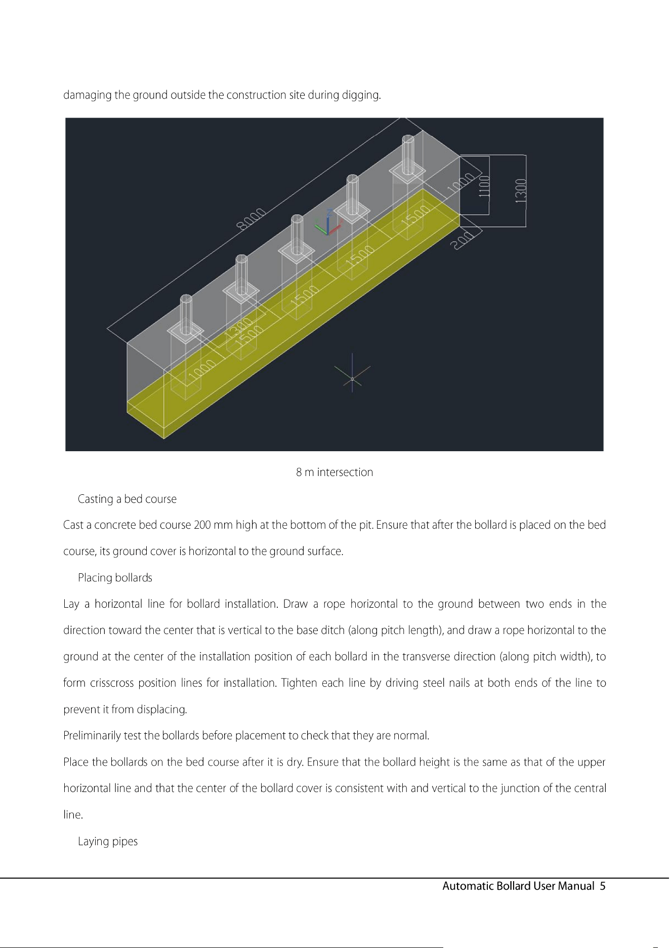
1. The total road length is
8000
mm
.
2. Dig a groove measuring
8000
mm x
1000
mm x
13000
mm
3. After a groove is dug
,
harden the foundation
200
mm high
when the drain pipe is deployed
.
Bury the
60
#
PVC pipe into the
hardened layer
200
mm high
.
4. After the hardened layer is dry
,
place the lifting column at the
center marked with
1500
.
5. Check whether the horizontal position is reached by using a
level gauge
.
②
③
④
⑤
⑥
⑦