
ProFace X TD User
Manual
P a g e
|
1
Copyright©2020ZKTECO CO., LTD. All rights reserved.
User
Manual
NetworkVideoRecorder( NEWGUI)
Date: January 2025
Doc Version: 1.0
English
Thank you for choosing our product. Please read the instructions carefully
before operation. Follow these instructions to ensure that the product is
functioning properly. The images shown in this manual are for illustrative
purposesonly.
For further details, please visit our Company’s website
www.zkteco.com.

Network Video Recorder
User
Manual
P a g e
|
2
Copyright©2025 ZKTECO CO., LTD. All rights reserved.
Copyright © 2025 ZKTECO CO., LTD. All rights reserved.
Without the prior written consent of ZKTeco, no portion of this manual can be copied or forwarded in any way or
form. All parts of this manual belong to ZKTeco and its subsidiaries (hereinafter the "Company" or "ZKTeco").
Trademark
is a registered trademark of ZKTeco. Other trademarks involved in this manual are owned by their
respectiveowners.
Disclaimer
This manual contains information on the operation and primarytenance of the ZKTeco Device. The copyright in
all the documents, drawings, etc. in relation to the ZKTeco supplied Device vests in and is the property of ZKTeco.
The contents hereof should not be used or shared by the receiver with any third party without express written
permission of ZKTeco.
The contents of this manual must be read as a whole before starting the operation and primarytenance of the
supplied Device. If any of the content(s) of the manual seems unclear or incomplete, please contact ZKTeco
before starting the operation and primarytenance ofthe said Device.
It is an essential pre-requisite for the satisfactory operation and primarytenance that the operating and
primarytenance personnel are fully familiar with the design and that the said personnel have received thorough
training in operating and primarytaining the machine/unit/Device. It is further essential for the safe operation of
the machine/unit/Device that personnel has read, understood, and followed the safety instructions contained in
the manual.
In case of any conflict between terms and conditions of this manual and the contract specifications, drawings,
instruction sheets or anyother contract-related documents, the contract conditions/ documents shall prevail. The
contract-specific conditions/documents shall applyin priority.
ZKTeco offers no warranty, guarantee, or representation regarding the completeness of any information
contained in this manual or any of the amendments made thereto. ZKTeco does not extend the warranty of any
kind, including, without limitation, any warranty of design, merchantability, or fitness for a particular purpose.
ZKTeco does not assume responsibility for any errors or omissions in the information or documents which are
referenced by or linked to this manual. The entire risk as to the results and performance obtained from using the
information is assumed by the user.
ZKTeco in no event shall be liable to the user or any third party for any incidental, consequential, indirect, special,
or exemplary damages, including, without limitation, loss of business, loss of profits, business interruption, loss of
business information or any pecuniary loss, arising out of, in connection with, or relating to the use of the
information contained in or referenced by this manual, even if ZKTeco has been advised of the possibility of such
damages.
This manual and the information contained therein may include technical, other inaccuracies or typographical
errors. ZKTeco periodically changes the information herein which will be incorporated into new
additions/amendments to the manual. ZKTeco reserves the right to add, delete, amend, or modify the
information contained in the manual from time to time in the form of circulars, letters, notes, etc. for better
operation and safety of the machine/unit/Device. The said additions or amendments are meant for improvement
/better operations of the machine/unit/Device and such amendments shall not give any right to claim any
compensation or damages under any circumstances.

Network Video Recorder
User
Manual
P a g e
|
3
Copyright©2025 ZKTECO CO., LTD. All rights reserved.
ZKTeco shall in no way be responsible (i) in case the machine/unit/Device malfunctions due to any non-
compliance of the instructions contained in this manual (ii) in case of operation of the machine/unit/Device
beyond the rate limits (iii) in case of operation of the machine and Device in conditions different from the
prescribed conditions of the manual.
The product will be updated from time to time without prior notice. The latest operation procedures and relevant
documents are available onhttp://www.zkteco.com.
If there isany issue related to the product, please contact us.
ZKTeco
Headquarters
Address
ZKTeco Industrial Park, No. 32, Industrial Road,
Tangxia Town, Dongguan, China.
Phone +86769-82109991
Fax +86755-89602394
Toknow
moreaboutourglobalbranches,visitwww.zkteco.com.
Aboutthe Company
ZKTecoisone of the world’s largest manufacturers ofRFID and Biometric (Fingerprint,Facial, and Finger- vein)readers.
Product offerings include Access Control readers and panels, Near & Far-range Facial Recognition Cameras,
Elevator/floor access controllers, Turnstiles, License Plate Recognition (LPR) gate controllers and Consumer products
including battery-operated fingerprint and face-reader Door Locks. Our security solutions are multi-lingual and
localized in over 18 different languages. At the ZKTeco state- of-the-art 700,000 square foot ISO9001-certified
manufacturing facility, we control manufacturing, product design, component assembly, and logistics/shipping, all
under one roof.
The founders of ZKTeco have been determined for independent research and development of biometric
verification procedures and the productization of biometric verification SDK, which was initially widely appliedinPC
security and identity authentication fields. With the continuous enhancement of the development and plenty of
market applications, the team has gradually constructed an identity authentication ecosystem and smart security
ecosystem, which are basedon biometric verification techniques. With years ofexperience in the industrialization of
biometric verifications, ZKTeco was officially established in 2007 and now has been one of the globally leading
enterprises in the biometric verification industry owning various patents and being selected as the National High-
techEnterprise for 6 consecutive years. Its productsare protected byintellectualproperty rights.
Aboutthe Manual
This manual introduces the product of
Network Video Recorder.
All figures displayed are for illustration purposes only. Figures in this manual may not be exactly
consistentwith theactualproducts.

Network Video Recorder
User
Manual
P a g e
|
4
Copyright©2025 ZKTECO CO., LTD. All rights reserved.
TABLE OF CONTENTS
1.
Installation -----------------------------------------------------------------------------------------------------------------------------------------------7
1.1.
Unpacking
Inspection
-------------------------------------------------------------------------------------------------------------------------- 7
1.2.
Hard Disk Installation
-----------------------------------------------------------------------------------------------------------------------------7
1.2.1.
NVR with Hard Disk
----------------------------------------------------------------------------------------------------------------------------------------7
2.
Getting
Started
----------------------------------------------------------------------------------------------------------------------------------------- 8
2.1.
Start Up and Shutdown
-------------------------------------------------------------------------------------------------------------------------- 8
2.1.1.
Start
Up
------------------------------------------------------------------------------------------------------------------------------------------------------8
2.1.2.
Shut
Down
------------------------------------------------------------------------------------------------------------------------------------------------- 9
2.2.
Login ------------------------------------------------------------------------------------------------------------------------------------------------ 9
2.3.
Using
Guide
--------------------------------------------------------------------------------------------------------------------------------------10
2.4.
Menu
Operation
------------------------------------------------------------------------------------------------------------------------------- 12
2.4.1.
Begin
Setup
----------------------------------------------------------------------------------------------------------------------------------------------12
3.
Preview
------------------------------------------------------------------------------------------------------------------------------------------------- 13
3.1.
Introduction of Preview
------------------------------------------------------------------------------------------------------------------------ 13
3.2.
Operations in Preview Mode
------------------------------------------------------------------------------------------------------------------ 15
3.3.
Using the Mouse in Preview
------------------------------------------------------------------------------------------------------------------- 16
4.
Playback
------------------------------------------------------------------------------------------------------------------------------------------------18
4.1.
Instant
Playback
-------------------------------------------------------------------------------------------------------------------------------- 18
4.2.
Playback by Normal Search
-------------------------------------------------------------------------------------------------------------------- 19
4.2.1.
Recording
Playback ------------------------------------------------------------------------------------------------------------------------------------ 19
4.2.2.
Playback by Event Search
------------------------------------------------------------------------------------------------------------------------------21
4.2.3.
Playback
Pictures
---------------------------------------------------------------------------------------------------------------------------------------21
5.
PTZ
Controls
------------------------------------------------------------------------------------------------------------------------------------------- 23
5.1.
Configuring PTZ Settings
---------------------------------------------------------------------------------------------------------------------- 23
5.2.
Setting PTZ Preset, Cruise Line, Trajectory & Scan Line
-------------------------------------------------------------------------------------24
5.2.1.
Preset
Setting
------------------------------------------------------------------------------------------------------------------------------------------- 24
5.2.2.
Cruise
Setting -------------------------------------------------------------------------------------------------------------------------------------------- 24
5.2.3.
Trajectory
Setting
---------------------------------------------------------------------------------------------------------------------------------------25
5.2.4.
Scan LineSetting
-----------------------------------------------------------------------------------------------------------------------------------------25
6.
Channel
Manage -------------------------------------------------------------------------------------------------------------------------------------- 26
6.1.
Channel Config --------------------------------------------------------------------------------------------------------------------------------- 26
6.1.1.
Search Device
-------------------------------------------------------------------------------------------------------------------------------------------- 26
6.2.
Regular
Configuration
------------------------------------------------------------------------------------------------------------------------29
6.2.1.
OSD Setting
---------------------------------------------------------------------------------------------------------------------------------------------29
6.2.2.
Image Parameters ------------------------------------------------------------------------------------------------------------------------------------- 30
6.2.3.
Media
Parameters
------------------------------------------------------------------------------------------------------------------------------------- 31

Network Video Recorder
User
Manual
P a g e
|
5
Copyright©2025 ZKTECO CO., LTD. All rights reserved.
6.2.4.
Tour Setting ----------------------------------------------------------------------------------------------------------------------------------------------32
6.2.5.
Channel Zero Setting --------------------------------------------------------------------------------------------------------------------------------- 33
6.3.
Regular
Detection
------------------------------------------------------------------------------------------------------------------------------34
6.3.1.
Video
Shelter ---------------------------------------------------------------------------------------------------------------------------------------------34
6.3.2.
Video
Lost
------------------------------------------------------------------------------------------------------------------------------------------------ 35
6.3.3.
Privacy
Mask
--------------------------------------------------------------------------------------------------------------------------------------------- 37
7.
Intelligence ---------------------------------------------------------------------------------------------------------------------------------------------38
7.1.
Intelligent Function
-------------------------------------------------------------------------------------------------------------------------- 38
7.1.1.
Crowd Situation ---------------------------------------------------------------------------------------------------------------------------------------- 38
7.1.2.
Perimeter Protection ----------------------------------------------------------------------------------------------------------------------------------40
7.1.3.
Object Left/Lost ---------------------------------------------------------------------------------------------------------------------------------------- 48
7.2. Intelligent Search ------------------------------------------------------------------------------------------------------------------------50
7.2.1.
Record Search -------------------------------------------------------------------------------------------------------------------------------------------50
7.2.2.
Snap Search ----------------------------------------------------------------------------------------------------------------------------------------------52
7.2.3.
Target Counting ----------------------------------------------------------------------------------------------------------------------------------------53
8.
Alarm ---------------------------------------------------------------------------------------------------------------------------------------------------- 54
8.1.
Alarm Abnormal
-------------------------------------------------------------------------------------------------------------------------------54
8.2.
Alarm Input
------------------------------------------------------------------------------------------------------------------------------------- 55
8.3.
Alarm
Output ------------------------------------------------------------------------------------------------------------------------------------ 57
8.4.
Alarm Log
----------------------------------------------------------------------------------------------------------------------------------------58
9.
Storage
Manage ---------------------------------------------------------------------------------------------------------------------------------------59
9.1.
Disk Manage -------------------------------------------------------------------------------------------------------------------------------------59
9.1.1.
Disk Configuration -------------------------------------------------------------------------------------------------------------------------------------59
9.1.2.
Record Calculate --------------------------------------------------------------------------------------------------------------------------------------- 61
9.2.
RAID Manage ------------------------------------------------------------------------------------------------------------------------------------ 62
9.2.1.
Disk RAID ------------------------------------------------------------------------------------------------------------------------------------------------- 62
9.3.
Group Manage ---------------------------------------------------------------------------------------------------------------------------------- 64
9.3.1.
Disk Grouping -------------------------------------------------------------------------------------------------------------------------------------------64
9.4.
Record Configuration ------------------------------------------------------------------------------------------------------------------------- 65
9.4.1.
Record Configuration ---------------------------------------------------------------------------------------------------------------------------------65
9.5.
Snap Config --------------------------------------------------------------------------------------------------------------------------------------66
9.5.1.
Snap Config ----------------------------------------------------------------------------------------------------------------------------------------------66
10. System
Manage
------------------------------------------------------------------------------------------------------------------------------------- 67
10.1.
System
Configuration
-----------------------------------------------------------------------------------------------------------------------67
10.1.1.
System Setting
--------------------------------------------------------------------------------------------------------------------------------------- 68
10.1.2.
Time Setting
-------------------------------------------------------------------------------------------------------------------------------------------70
10.1.3.
Preview Setting
-------------------------------------------------------------------------------------------------------------------------------------- 72
10.1.4.
System Information
-------------------------------------------------------------------------------------------------------------------------------- 74
10.1.5.
Security Setting
-------------------------------------------------------------------------------------------------------------------------------------- 79

Network Video Recorder
User
Manual
P a g e
|
6
Copyright©2025 ZKTECO CO., LTD. All rights reserved.
10.2.
Network
Configuration
----------------------------------------------------------------------------------------------------------------------80
10.2.1.
Basic Setting
-------------------------------------------------------------------------------------------------------------------------------------------80
10.2.2.
Advanced Setting
----------------------------------------------------------------------------------------------------------------------------------- 85
10.2.3.
Platform Setting
------------------------------------------------------------------------------------------------------------------------------------- 86
10.2.4.
Network Monitoring
------------------------------------------------------------------------------------------------------------------------------- 88
10.2.5.
Network Testing
------------------------------------------------------------------------------------------------------------------------------------- 89
10.3.
User
Configuration
---------------------------------------------------------------------------------------------------------------------------90
10.3.1.
User Management
---------------------------------------------------------------------------------------------------------------------------------- 90
10.3.2.
Online User
-------------------------------------------------------------------------------------------------------------------------------------------- 92
10.4.
System Log
--------------------------------------------------------------------------------------------------------------------------------------- 93
10.4.1.
System Log
-------------------------------------------------------------------------------------------------------------------------------------------- 93
Network Video Recorder
User
Manual
P a g e
|
7
Copyright©2025 ZKTECO CO., LTD. All rights reserved.
1.
Installation
1.1.
Unpacking
Inspection
During installation of the NVR:
Ensure the device is installed in a well-ventilated, dust-free environment.
The device is designed for indoor use only.
Keep all liquids away from the device.
Ensure environmental conditions meet factory specifications.
Power down the device before connecting and disconnecting accessories and peripherals.
1.2.
Hard Disk Installation
Before you start:
Disconnect the power from the NVR before installing a hard disk drive (HDD). A factory recommended HDD should be
used for this installation.
Tools Required:
Screwdriver.
1.2.1.
NVR with Hard Disk
Steps:
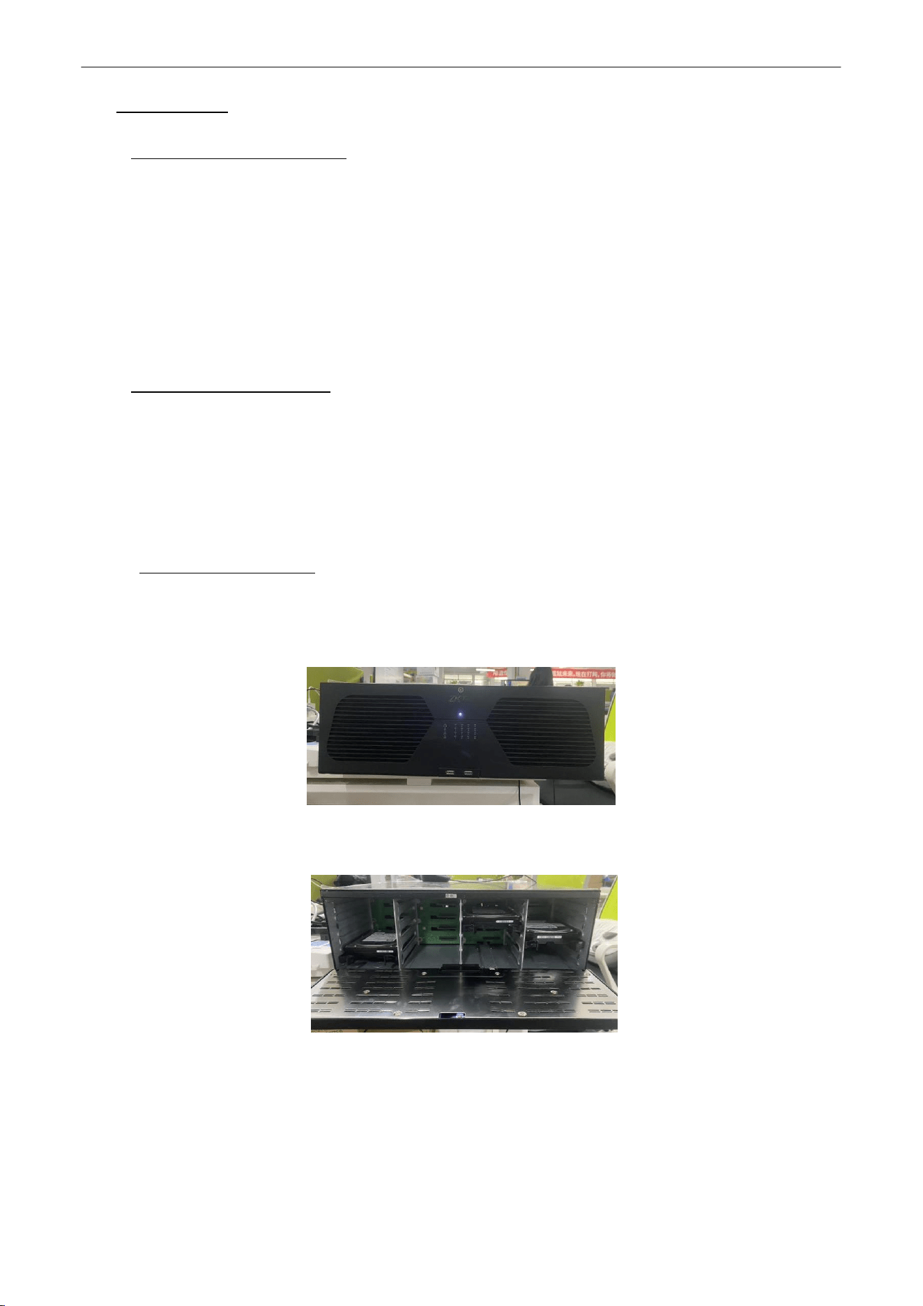
1.
Open the front panel,as shown in figure 1.2.1.1.
Figure 1.2.1.1 Front Panel
2.
Insert the hard disk along the slot and close it,as shown in figure 1.2.1.2.
Figure 1.2.1.2 Hard Disk Slot

Network Video Recorder
User
Manual
P a g e
|
8
Copyright©2025 ZKTECO CO., LTD. All rights reserved.
2.
Getting
Started
2.1.
Start Up and Shutdown
2.1.1.
Start
Up
Plug in the power cord, press the power switch, the power indicator light should turn bright. The device will begin to
start. After the device starts up, the video output defaults to multiple screen output mode
,
as shown in figure 2.1.1.
Figure 2.1.1 Start Up
Network Video Recorder
User
Manual
P a g e
|
9
Copyright©2025 ZKTECO CO., LTD. All rights reserved.
2.1.2.
Shut
Down
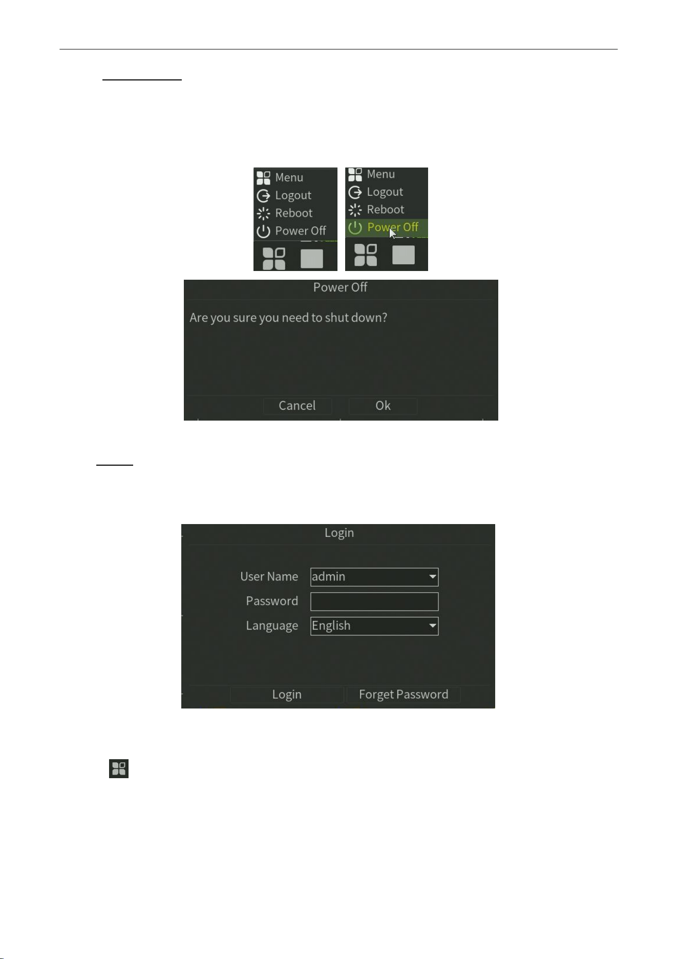
Option 1:
Long press the power key on front panel to shutdown the device .
Option 2:
Click
Start
>
Power Off
>
OK
(
Prompt
:
It is recommended to use this way, in order to avoid damage to
the device when suddenly powered off.)
Figure 2.1.2 Shut Down Menu
2.2.
Login
If NVR first start-up or has logged out, you must login the device before operating the menu and other functions, as
shown in figure 2.2.1 and figure 2.2.2.
Figure 2.2.1 Login Interface
Steps:
3.
Click button on the top of screen.
4.
Click Login in the drop-down menu.
5.
Input the
Password
in the pop-up interface (Default password: 123456).
6.
Click Login to log in.
Network Video Recorder
User
Manual
P a g e
|
10
Copyright©2025 ZKTECO CO., LTD. All rights reserved.
2.3.
Using
Guide
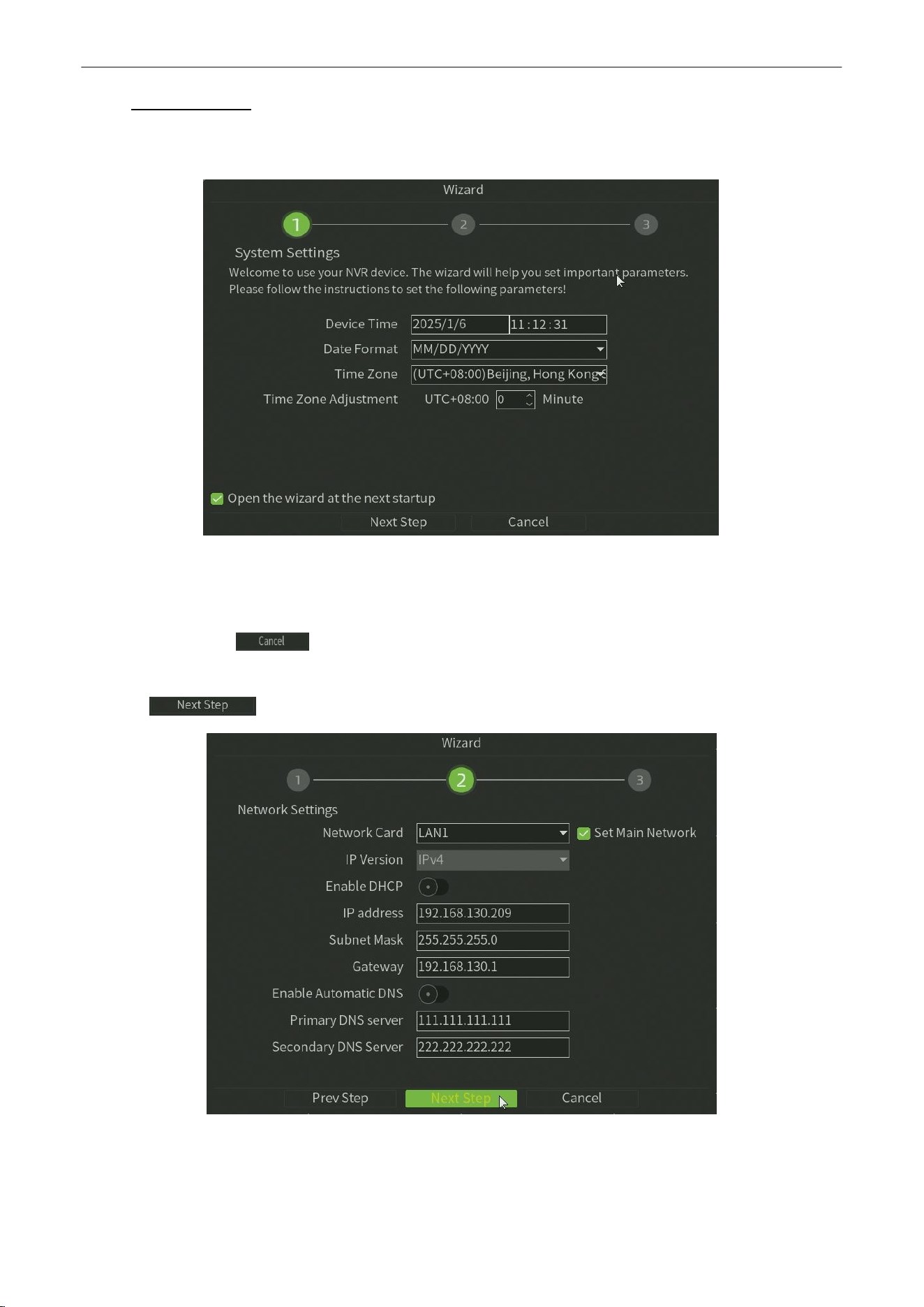
The Guide starts once login, as shown in figure 2.3.
Figure 2.3 System Settings
Operating the Guide:
1.
The Guide can walk you through some basic settings of the NVR. If you don’t want to use the Guide at that
moment, click the button. You can also choose to use the Guide next time by leaving the “Next time
no longer display” check-box unchecked.
2.
Click button to enter theNetwork Setting window, as shown in figure 2.4.
Figure 2.4 Network Setting
Network Video Recorder
User
Manual
P a g e
|
11
Copyright©2025 ZKTECO CO., LTD. All rights reserved.
3.
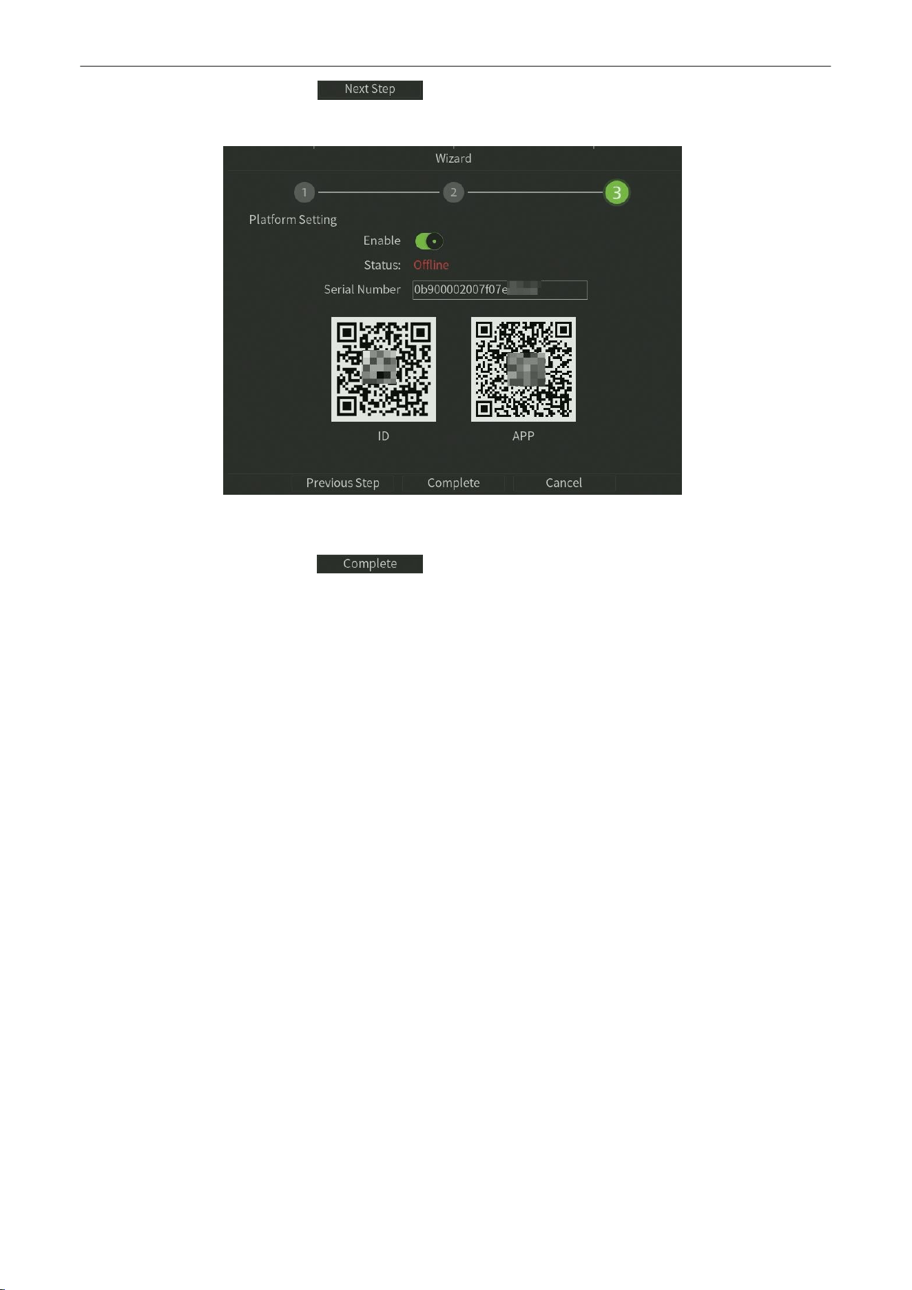
After the Network Setting, click button to enter the Platform Setting window, as shown in figure
2.5.
Figure 2.5 Platform Setting
4.
After the Platform setting, click button to complete the basic configuration and then enter into
preview page.
Network Video Recorder
User
Manual
P a g e
|
12
Copyright©2025 ZKTECO CO., LTD. All rights reserved.
2.4.
Menu
Operation
After the user login successfully, according to the interface of toolbar to perform associated settings, as shown in figure
2.6.
Figure 2.6 Menu Operation
2.4.1.
Begin
Setup
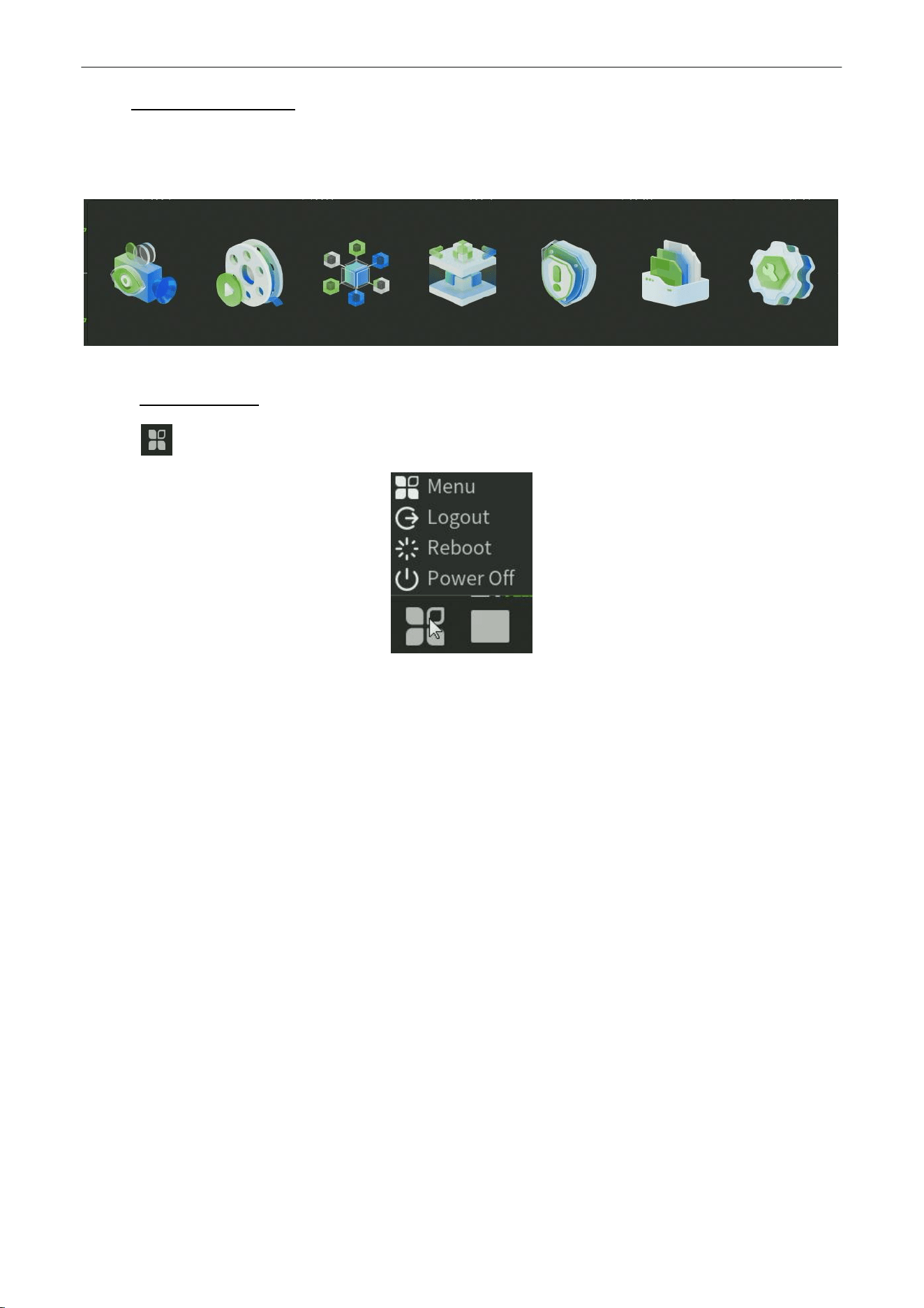
Click the icon, it will pop-up the interface as show in figure 2.7.
Figure 2.7 Begin Setup
1.
Menu
:
Click
Menu
button,Bring up the menu option window.
2.
Logout: Click Logout button, can exit the current user.
3.
Reboot: Click Reboot button and confirm, the device will automatically reboot.
4.
Power Off:
Click
Power Off
button and confirm, the device will automaticallyshutdown.
Network Video Recorder
User
Manual
P a g e
|
13
Copyright©2025 ZKTECO CO., LTD. All rights reserved.
3.
Preview
3.1.
Introduction of Preview
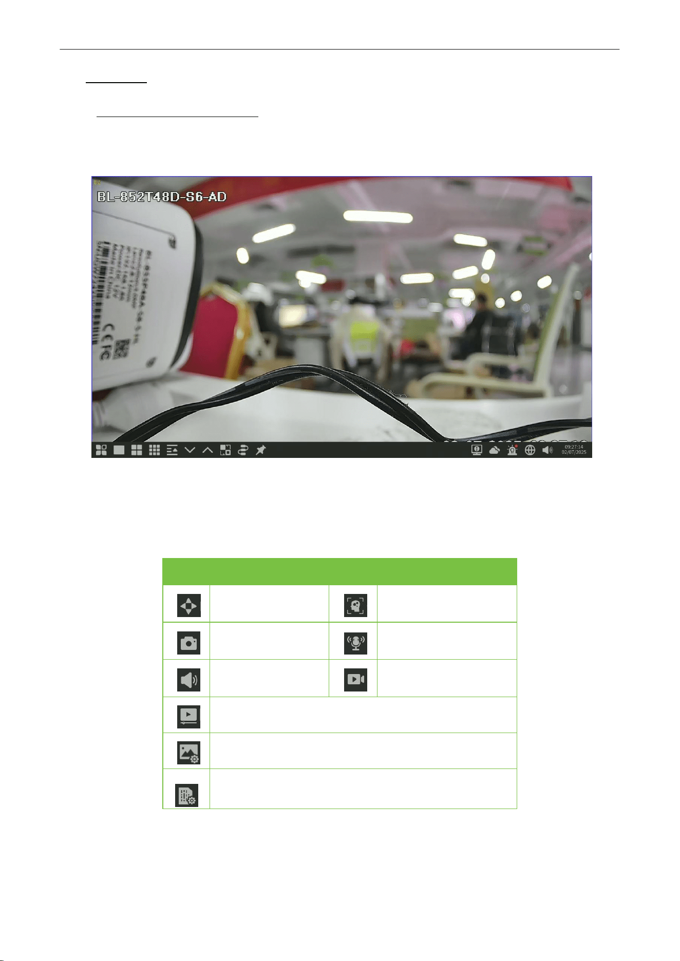
Preview shows you the video image getting from each camera in real time. The NVR will automatically enter live view
mode when powered on, as shown in figure 3.1.
Figure 3.1 Preview Interface
Channel Preview Icons:
In the Preview mode, there are hide icons on the screen of each channel, which shows when you move the mouse to
the bottom of channel.
Icons
Description
Icons
Description
Open/Close PTZ
Show/Hide Smart
detection
Snapshot
Open/Close Voice
Intercom
Open/Close
Channel Audio
Manual Recording
On/Off
Instant
Playback
Mediaparameters
Bit Stream Parameters
Table 3.1 Preview Icon Description
Network Video Recorder
User
Manual
P a g e
|
14
Copyright©2025 ZKTECO CO., LTD. All rights reserved.
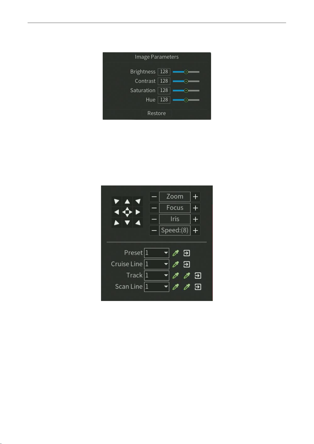
Media parameters :
May revise the brightness, contrast, saturation and hue of the channel that the current mouse
selected, one click to restore the default value when necessary, as shown in figure 3.2.
Figure 3.2 Media Parameters
PTZ/Preset/Cruise/Pattern:
Please confirm whether the related parameters setting is correct before control the PTZ. After setting up parameters,
select the channel to be controlled in the preview interface, then control the direction of the lens, focal length, focus,
aperture amplification and narrow in PTZ operation interface, and adjust the speed of PTZ, as shown in figure 3.3. See
below the detailed operation of PTZ control part.
Figure 3.3 PTZ Control
Network Video Recorder
User
Manual
P a g e
|
15
Copyright©2025 ZKTECO CO., LTD. All rights reserved.
3.2.
Operations in Preview Mode
In preview mode, there are many functions provided. The functions are listed below.
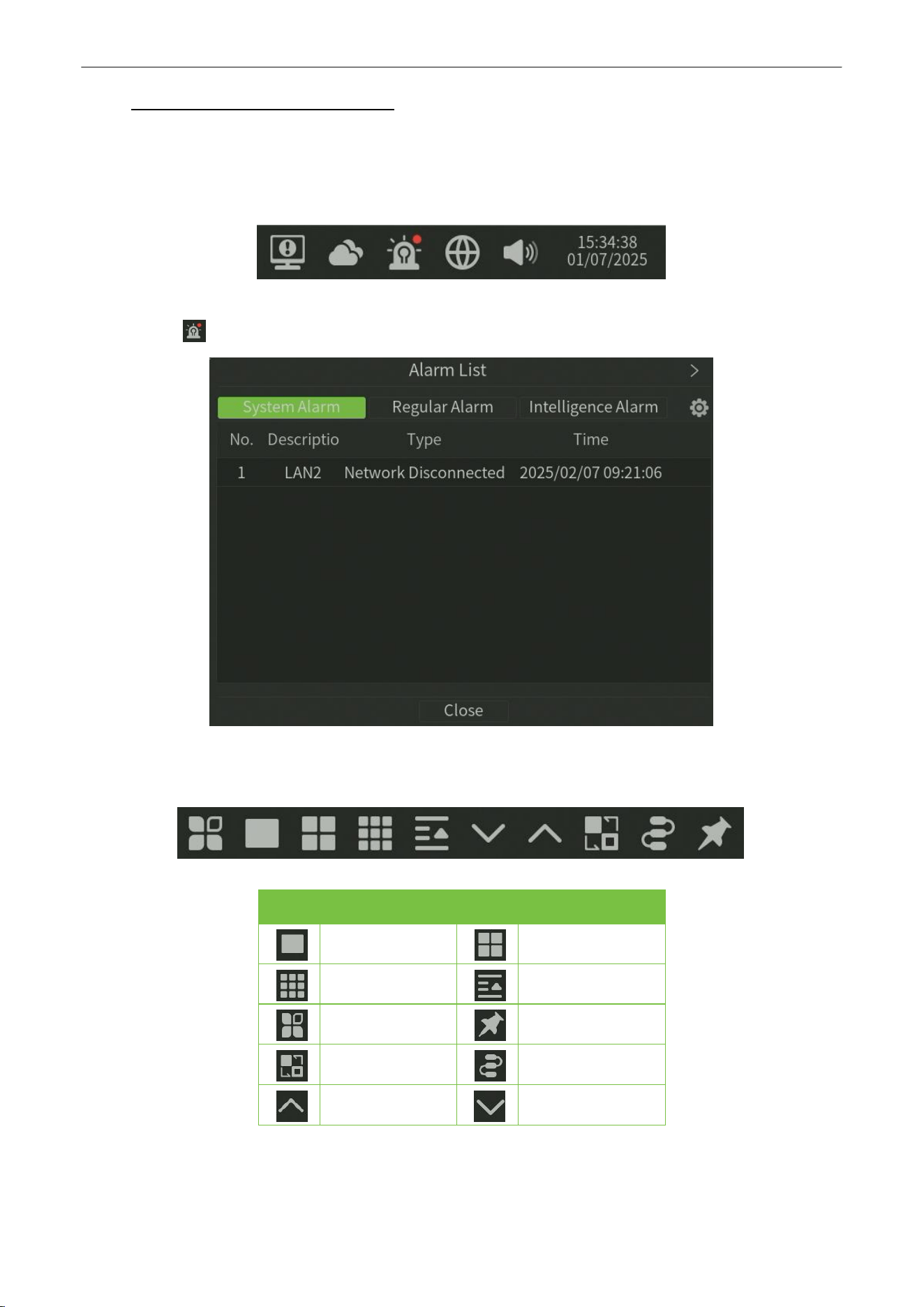
Real-time Alarm Information:
On the bottom right corner, there is a real-time alarm information, as shown in figure 3.4.
Figure 3.4 Alarming
When you click , it will pop-up the alarm information, as shown in figure 3.5
Figure 3.5 Alarm Information
Other Functions:
Icons
Functions
Icons
Description
1 Split Screen
4 Split Screen
9 Split Screen
ALL Split Scree
n
Menu button
Peg
CruiseonSetting
LinkagePreview
PageUp
PageDown
Table 3.2 Other Function Description

Network Video Recorder
User
Manual
P a g e
|
16
Copyright©2025 ZKTECO CO., LTD. All rights reserved.
3.3.
Using the Mouse in Preview
Name
Description
Menu
Select and enter menu
Wizard
Select and enter Wizard Interface
PTZ
Control
OpenthePTZinterface
Image Parameters
Select and enter ISP Interface
Channel
SelectandenterChannelManageInterface
Playback
Select andenterPlaybackManageInterface

Network Video Recorder
User
Manual
P a g e
|
17
Copyright©2025 ZKTECO CO., LTD. All rights reserved.
Four Screens
Select and enter 4 Split Screen mode.
Six Screens
Select and enter 6 Split Screen mode.
Eight Screens
Select and enter 8 Split Screen mode.
Nine Screens
Select and enter 9 Split Screen mode.
Thirteen
Screens
Select and enter 13 Split Screen mode.
SIxteen Screens
Select and enter 16 Split Screen mode.
Twenty-five Screens
Select and enter 25 Split Screen mode.
Thirty-six Screens
Select and enter 36 Split Screen mode.
forty-nine Screens
Select and enter 36 Split Screen mode.
Sixty-four Screens
Select and enter 64 Split Screen mode.
Prev Page
Switch to the previous screen.
Next Page
Switch to the next screen.
Table 3.3 Right Click Function Description
Network Video Recorder
User
Manual
P a g e
|
18
Copyright©2025 ZKTECO CO., LTD. All rights reserved.
4.
Playback
4.1.
Instant
Playback
Purpose:
Playback the recorded video files of a specific channel in the live view mode.
Steps:
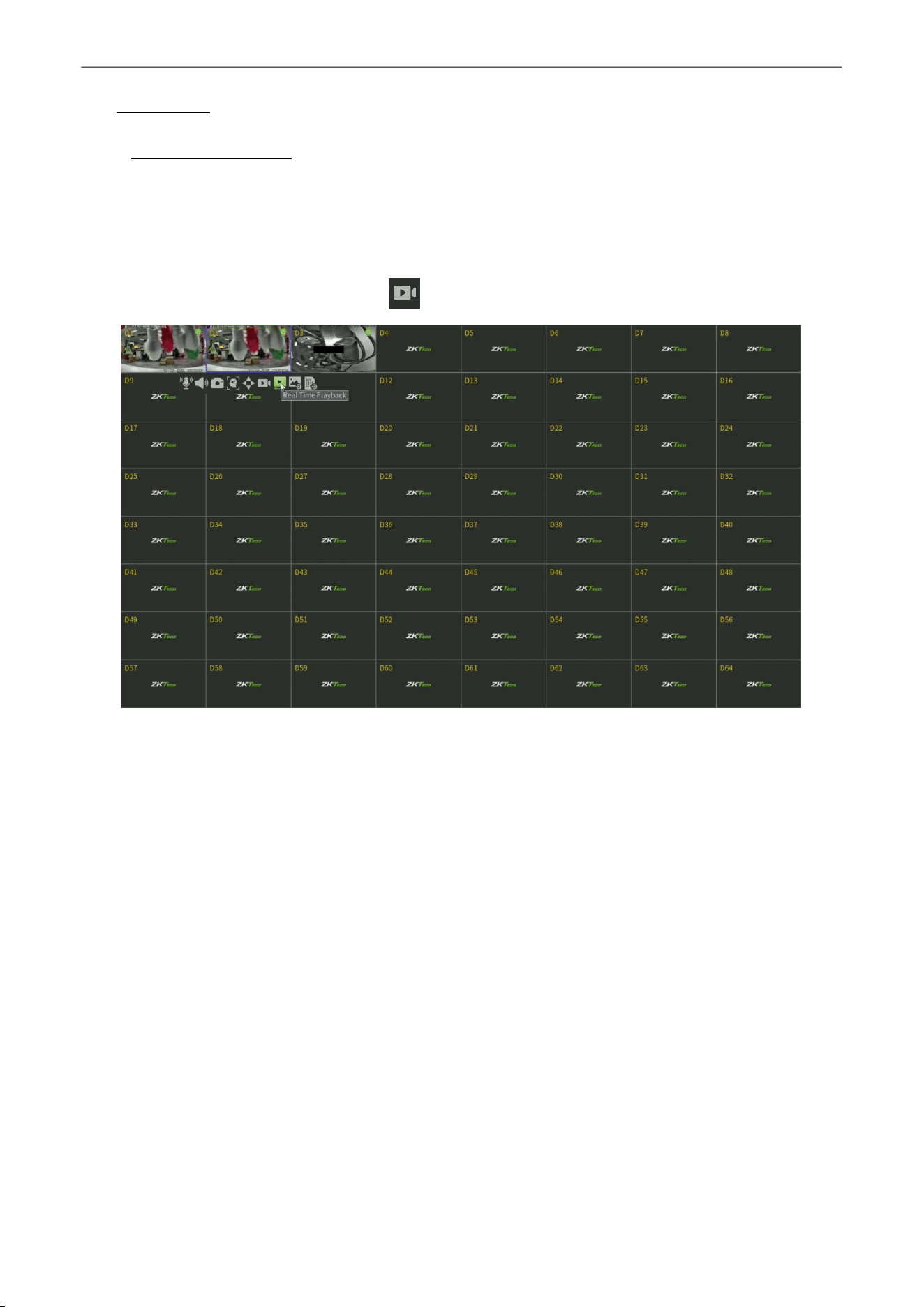
Select a channel in live view mode and click the button in the bottom of the channel, as shown in figure 4.1.
Figure 4.1 Instant Playback
Network Video Recorder
User
Manual
P a g e
|
19
Copyright©2025 ZKTECO CO., LTD. All rights reserved.
4.2.
Playback by Normal Search
4.2.1.
Recording
Playback
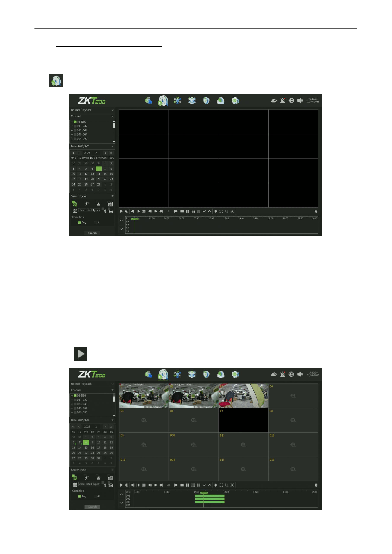
Click icon to enter the Playback interface, as shown in figure 4.2.
Figure 4.2 Normal Playback Interface
Playback by Time
Purpose:
Playback video files recorded in specified time duration. Multi-channel simultaneous playback is supported.
Steps:
1.
Enter playback interface.
2.
Check the check-box of channel(s) in the channel list and then click to select the date on the calendar.
3.
Select the Search Type and Condition then Click Search to search the record
4.
Click the button to start playback, as shown in figure 4.3.
Figure 4.3 Video Playback
Network Video Recorder
User
Manual
P a g e
|
20
Copyright©2025 ZKTECO CO., LTD. All rights reserved.
Note:
If there are record files for that camera in that day, in the calendar, the icon for that day is displayed as
. Otherwise it is displayed as .
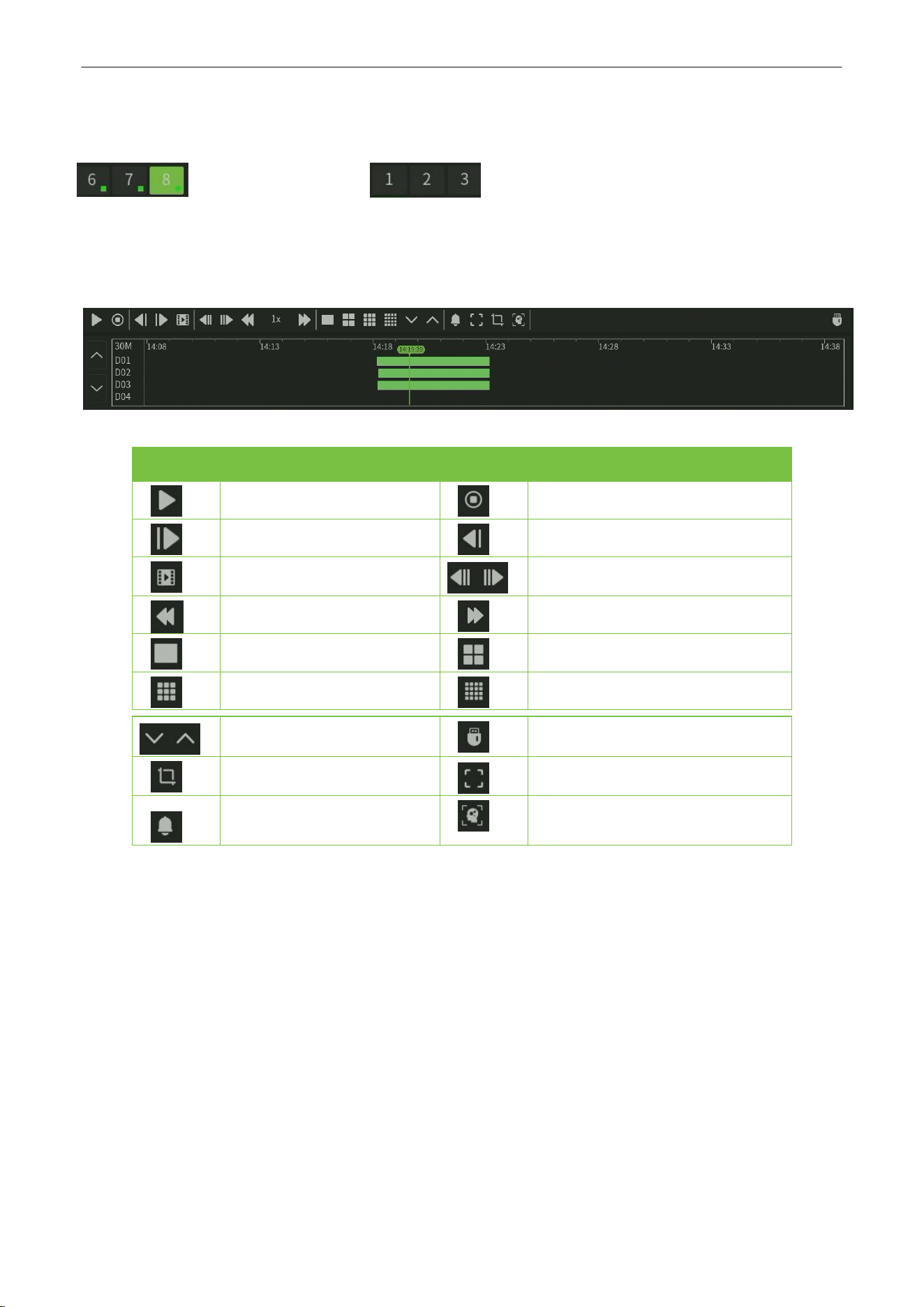
Playback Interface
You can use the toolbar in the bottom part of Playback interface to control playing progress, as shown in
figure4.4.
Figure 4.4 Playback Toolbar
Button
Operation
Button
Operation
Play/Pause
Stop
Playback Forward
Playback Backward
Single Frame
30SecondsForward/Backward
Speed Down
Speed Up
1 Split Screen
4 Split Screen
9* Split Screen
16 Split Screen
PageUp/Page Down
Backup
Capture
Full Screen
Sound Adjust
Hide/Show the time bar
Table 4.1 Detailed Explanation of Playback Toolbar
Network Video Recorder
User
Manual
P a g e
|
21
Copyright©2025 ZKTECO CO., LTD. All rights reserved.
4.2.2.
Playback by Event Search
Purpose:
Playback record files on one or several channels searched out by event type (e.g. alarm detection, motion).
Steps:
1.
Enter the Playback interface.
2.
Select the Retrieving type: There are many types you can select, such as Count Alarm, Motion, Across the line,
Regional, Alarm detection and object left/Loss etc. .
3.
Click the Search button to get the search result information.
4.
Click button to playback the file.
4.2.3.
Playback
Pictures
Purpose:
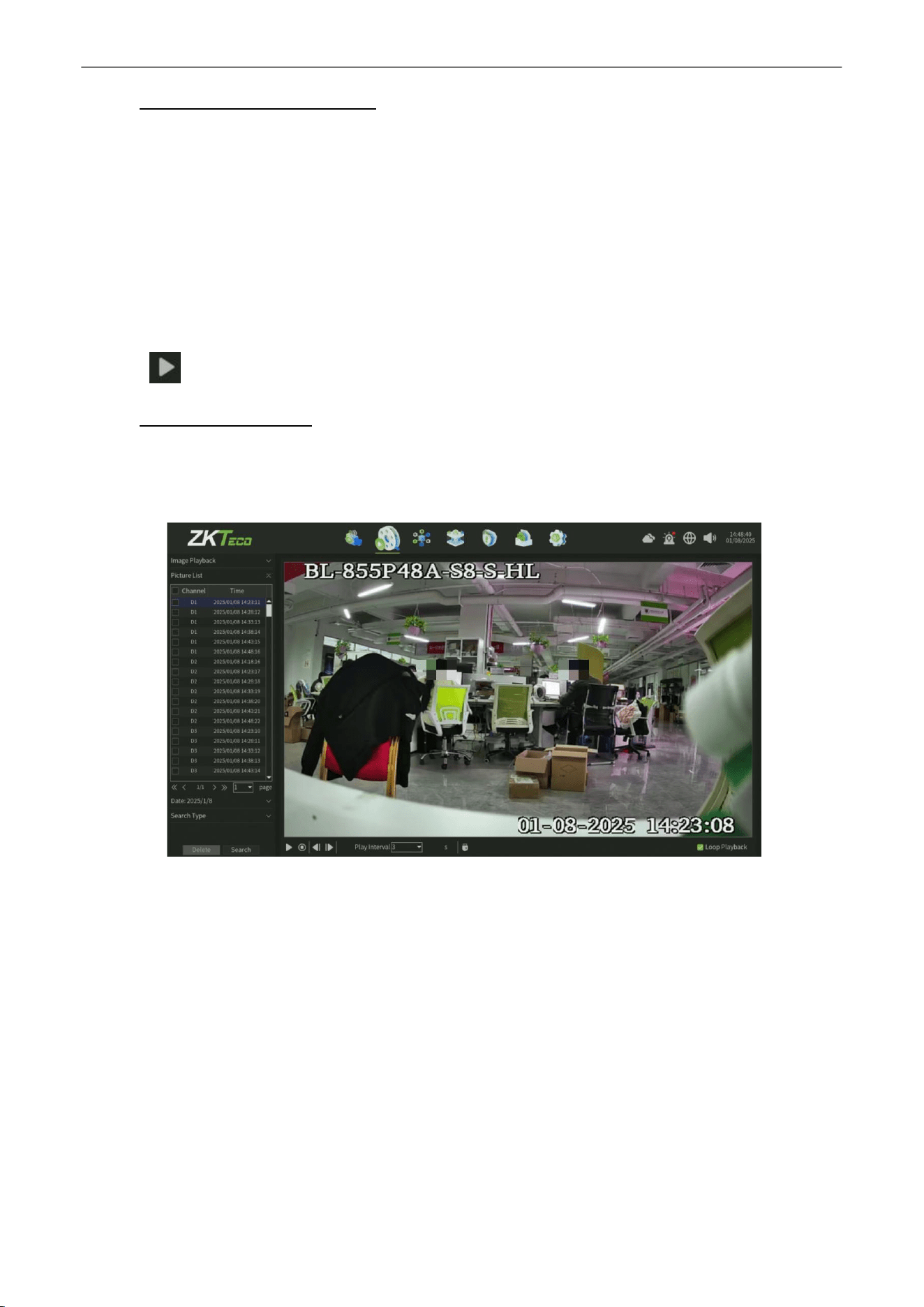
The captured pictures stored in the HDD of device can be searched and viewed, as shown in figure 4.5.
Figure 4.5 Picture Playback
Steps:
1.
Enter playback interface.
2.
Select playback modes: Image playback.
3.
Select Search by day or Search by time.
4.
Select Picture source: IPC Snapshot (preview snapshot) or Playback Snapshot.
5.
Choose Condition:Any or All.
6.
Select Retrieving type.
7.
Select Search Channel.
8.
Click Search button to search for the capture picture.
9.
Check the check-box after the picture listed, then click to view the picture.
10.
The toolbar in the bottom of playback interface can be used to control playing process.
Network Video Recorder
User
Manual
P a g e
|
22
Copyright©2025 ZKTECO CO., LTD. All rights reserved.
Button
Function
Button
Function
Play/Stop
Stop
Next
picture
Last
picture
Table 4.2 Detailed Explanation of Playback Toolbar
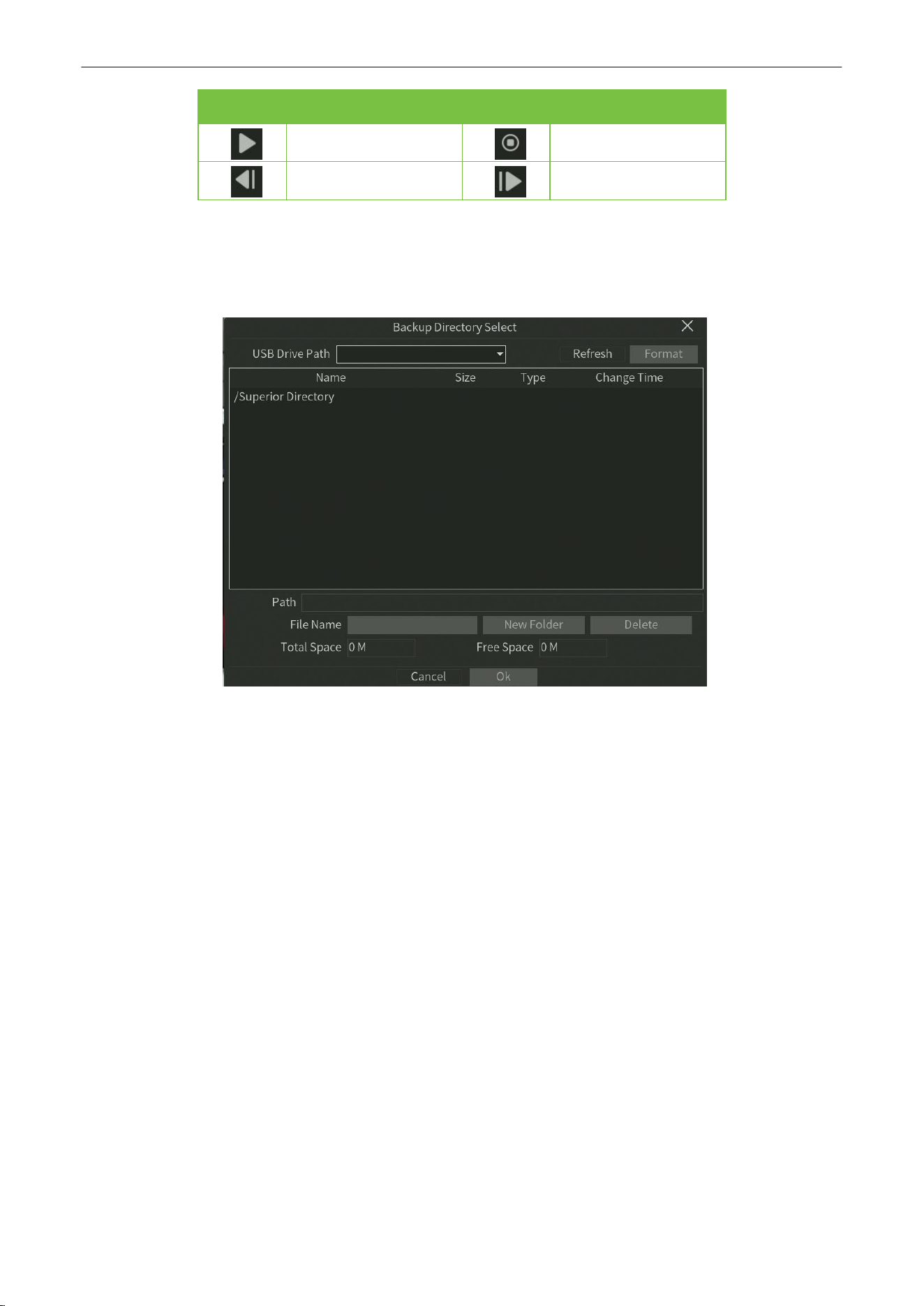
Note:
Click the check-box of the picture listed, then click Backup button, can enter the Snapshot back-up interface, as
shown in figure 4.6.
Figure 4.6 Snapshot Backup
Network Video Recorder
User
Manual
P a g e
|
23
Copyright©2025 ZKTECO CO., LTD. All rights reserved.
5.
PTZ
Controls
5.1.
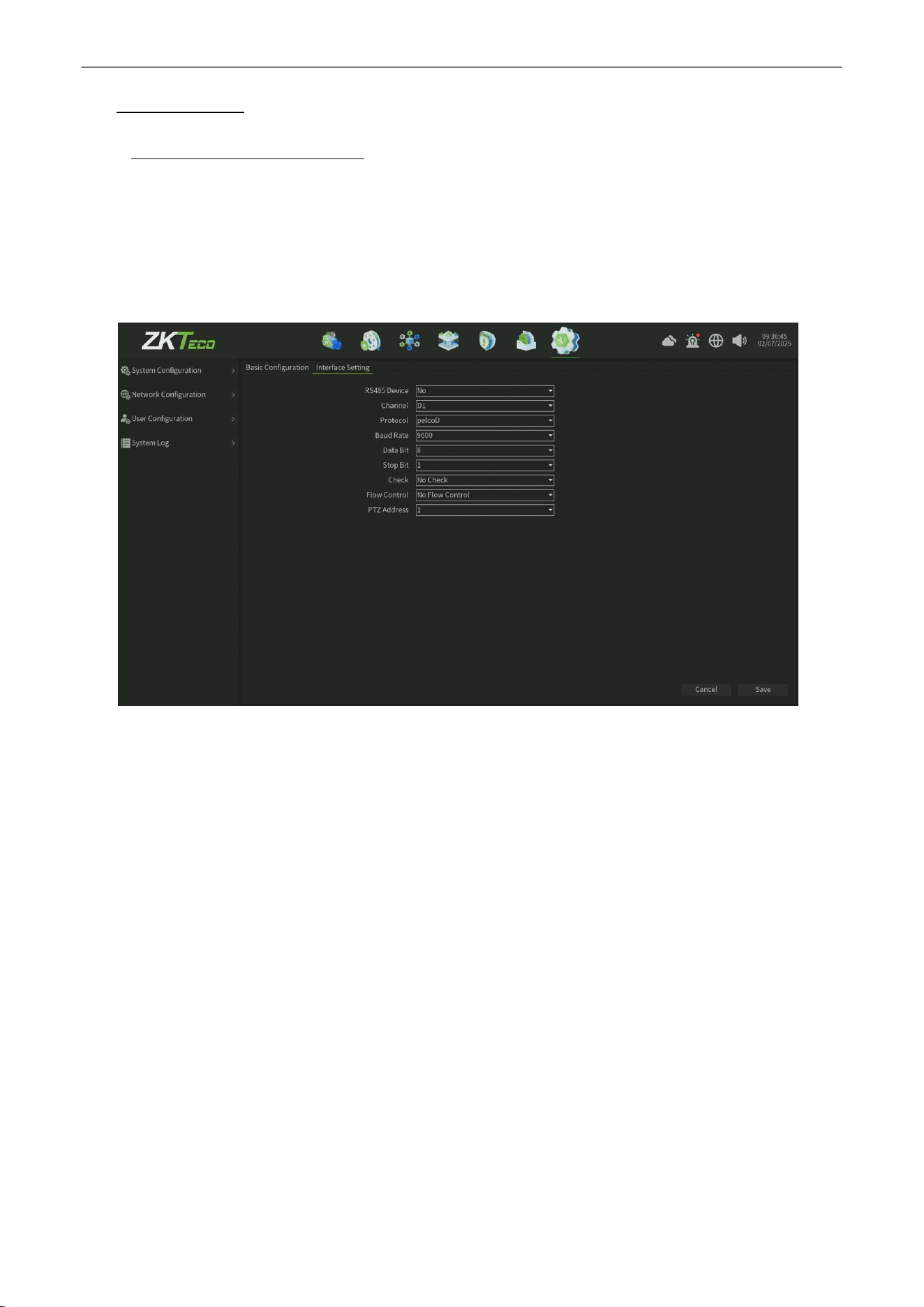
Configuring PTZ Settings
Follow the procedure to set the parameters for PTZ. The configuring of the PTZ parameters should be done before you
control the PTZ camera.
Steps:
1.
Enter the PTZ Setting interface, as shown in figure 5.1, click
System > System configuration >
SystemSetting
.
Figure 5.1 PTZ General Setting Interface
2.
Set the parameter of PTZ:
•
Channel: Choose the channel.
• Protocol:Choosetheprotocol foryourPTZ.
•
Decoder Address:
Choose the decoder address.
• BaudRate:Selectthebaudrate.
•
Data Bit: Select the data bit.
•
Stop Bit:
Select the stop bit.
•
Check: Select the check, No Check by default.
•
Flow Control: Select the flow control, No Flow Control by default.
3.
Click Save button to save the settings.
Network Video Recorder
User
Manual
P a g e
|
24
Copyright©2025 ZKTECO CO., LTD. All rights reserved.
5.2.
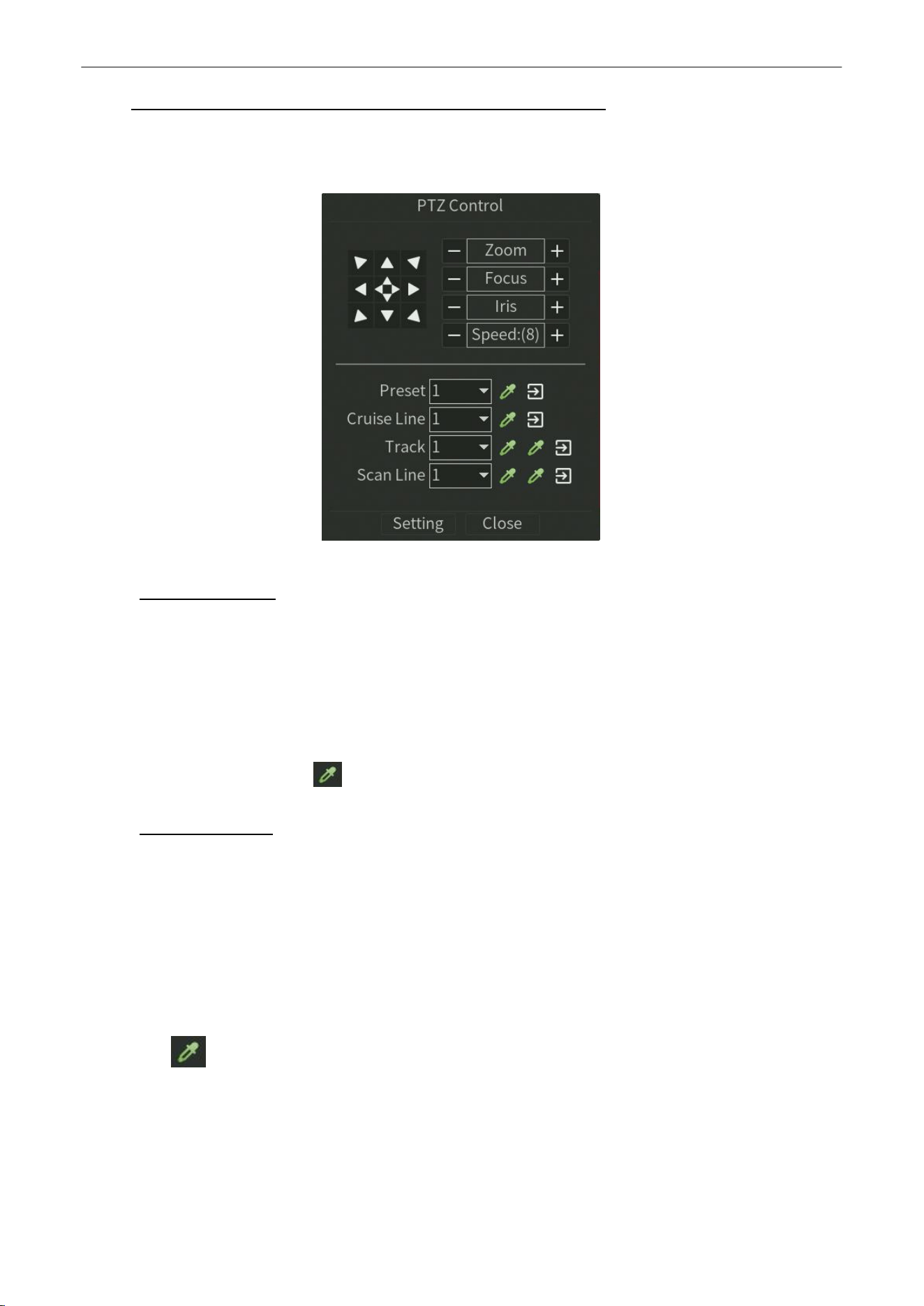
Setting PTZ Preset, Cruise Line, Trajectory & Scan Line
Before you start:
Please make sure that the preset, cruise and pattern should be supported by PTZ protocols, as shown in figure 5.2.
Figure 5.2 PTZ Setting Interface
5.2.1.
Preset
Setting
Follow the steps to set the Preset location which you want the PTZ camera to point to when an event takes place.
Steps:
1.
Use the directional button to wheel the camera to the location where you want to set preset, and the zoom and focus
operations can be recorded in the preset as well.
2.
Setting the name of preset, click button to save the preset. Repeat the above steps to save more presets.
5.2.2.
Cruise
Setting
Purpose:
Cruise can be set to move the PTZ to different locations and have it stay there for a set duration before moving on to the next
location. The locations are corresponding to the presets. The presets can be set following the steps above in
PresetSetting
.
Steps:
1.
Select cruise No. in the drop-down list of cruise.
2.
Click the button to add key points for cruise, as shown in figure 5.3.

Network Video Recorder
User
Manual
P a g e
|
25
Copyright©2025 ZKTECO CO., LTD. All rights reserved.
Figure5.3 Tour Line
1.
Configure key point parameters, such as the key point No., duration of staying for one key point and speed of cruise. The
key point is corresponding to the preset. The Key Point No. determines the order at which the PTZ will follow while
cycling through the cruise. The Cruise time refers to the time span to stay at the corresponding key point. The
Cruise
Speed
defines the speed at which the PTZ will move from one key point to the next.
2.
Click the Add button to add the next key point to the patrol.
3.
After finish setting, click OK button.
5.2.3.
Trajectory
Setting
Purpose:
Patterns can be set by recording the movement of the PTZ. You can call the pattern to make the PTZ movement according to
the predefined path.
Steps:
1.
Choose pattern number in the drop-down list.
2.
Click button to begin and click corresponding buttons in the control panel to move the PTZ camera, then click
button to end. The movement of the PTZ is recorded as the pattern.
5.2.4.
Scan Line Setting
Steps:
1.
Select a number, use the directional button to wheel the camera to the location where you want to set starting point,
click button.
2.
Wheel the camera to the location where you want to set end point, click button.
3.
Click button, the PTZ camera will move from the starting point to the end point.
Network Video Recorder
User
Manual
P a g e
|
26
Copyright©2025 ZKTECO CO., LTD. All rights reserved.
6.
Channel
Manage
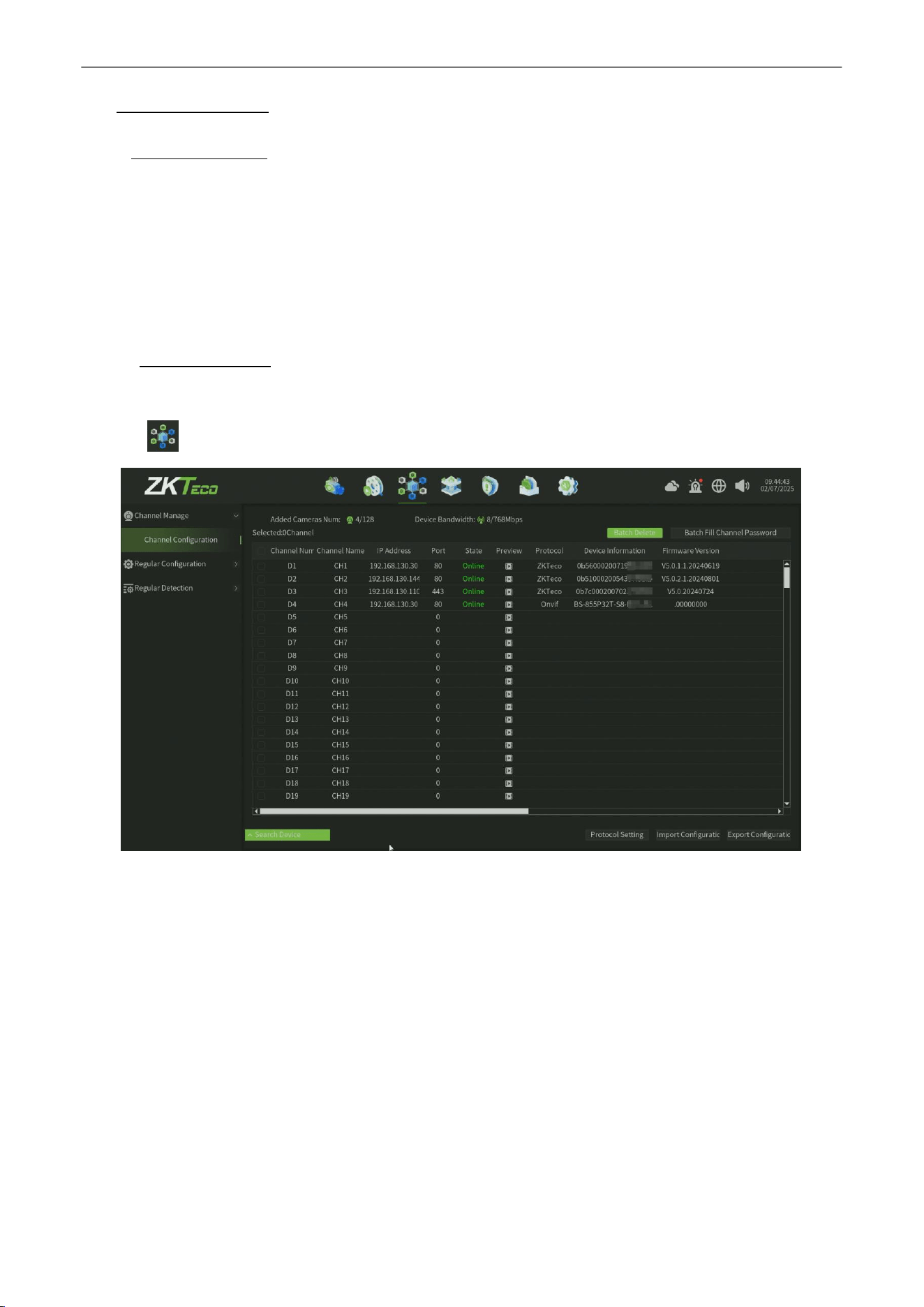
6.1.
Channel Config
Purpose:
Before you can get live video or record the video files, you should add the network cameras to the connection list of the
device.
Before you start:
Ensure the network connection is valid and correct, and the IP camera to add has already been activated.
6.1.1.
Search Device
Steps:
1.
Click icon , enter into the Channel Config interface, as shown in figure 6.1.
Figure 6.1. Quick Adding IP Camera Interface
2.
Click
Search Device
button, it will automatically search all the IP cameras in the same network with NVR.
3.
After that ,Also you can select the different Protocol Type(
ZKTeco
,
ONVIF
)firstly, then click
search.
4.
After the Stop time out,u can select the camera you want to add into NVR,or search again,By the way ,you also can
choose the Add method (Do not modify IP address,Force Modify IP Address,Modify IP address when unable
connected
),as show in figure 6.2
Network Video Recorder
User
Manual
P a g e
|
27
Copyright©2025 ZKTECO CO., LTD. All rights reserved.
Figure 6.2 Adding IP Camera with conditions
5.
Before adding the camera , note to input the camera username and password;
6.
Or you can choose to
Manually Add
the IP camera by editing the parameters in the corresponding text field and then
click the OK button to add it, as shown in figure 6.3.
Figure 6.3 Manually Adding IP Camera Interface
Network Video Recorder
User
Manual
P a g e
|
28
Copyright©2025 ZKTECO CO., LTD. All rights reserved.
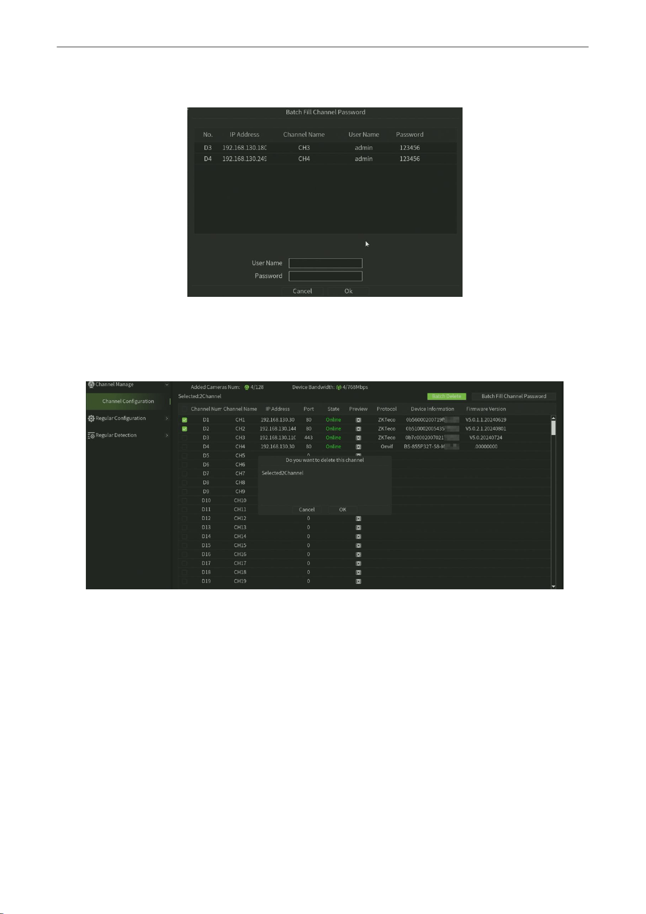
7.
You can click Batch Fill Channel Password button to input the IP Camera username and password batchly,as shown
in figure6.4.
Figure 6.4 Batch Fill IP Camera username and Password
8.
After adding the IP Camera, if you want delete some channels ,you can select the check -box of channels and then click
the Batch Delete button and click OK button to confirm,as shown in figure 6.5.
Figure 6.5 Batch Delete IP Camera
Network Video Recorder
User
Manual
P a g e
|
29
Copyright©2025 ZKTECO CO., LTD. All rights reserved.
6.2.
Regular
Configuration
6.2.1.
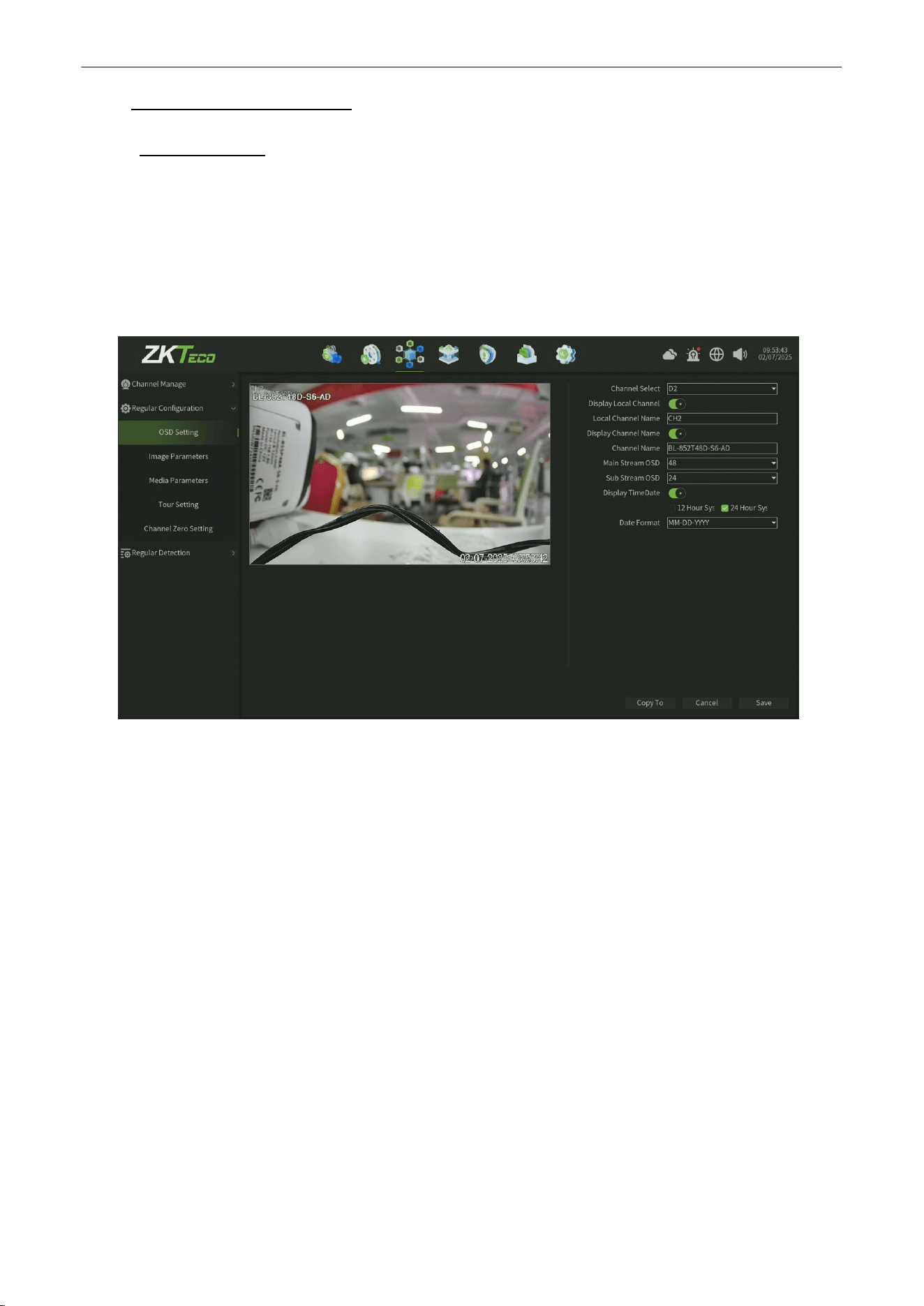
OSD Setting
Purpose:
You can configure the OSD (On-screen Display) settings for the camera, including camera name, date
/time, etc.
Steps:
1.
Enter the OSD Setting interface. Click
Channel > Regular config >OSD Setting,
as shown in figure 6.6.
Figure 6.6 OSD Setting interface
2.
Select the channel of camera to configure OSD settings.
3.
Local Channel Name setting.
1)
Check the check-box before
Display Local Chan
, enter the
Local Chan Name
in
thetextfield.
2)
Click
Save
button, the name that enter will show on the screen. You can use the mouse to click and drag the
text frame on the window to adjust the OSD position.
4.
IP Camera Name setting (configure camera interface).
1)
Check the check-box before
Display Chan Name
, then enter the
Channel Name
in
thetext field.
2)
Click
Save b
utton, the name that enter will show on the screen, you can use the mouse to click and drag the text
frame on the window to adjust the OSD position.
5.
IP camera TimeDate setting(configure camera interface).
1)
Check the check-box before
Display TimeDate.
2)
Select the Date & Time Format (should be supported by the camera).
Network Video Recorder
User
Manual
P a g e
|
30
Copyright©2025 ZKTECO CO., LTD. All rights reserved.
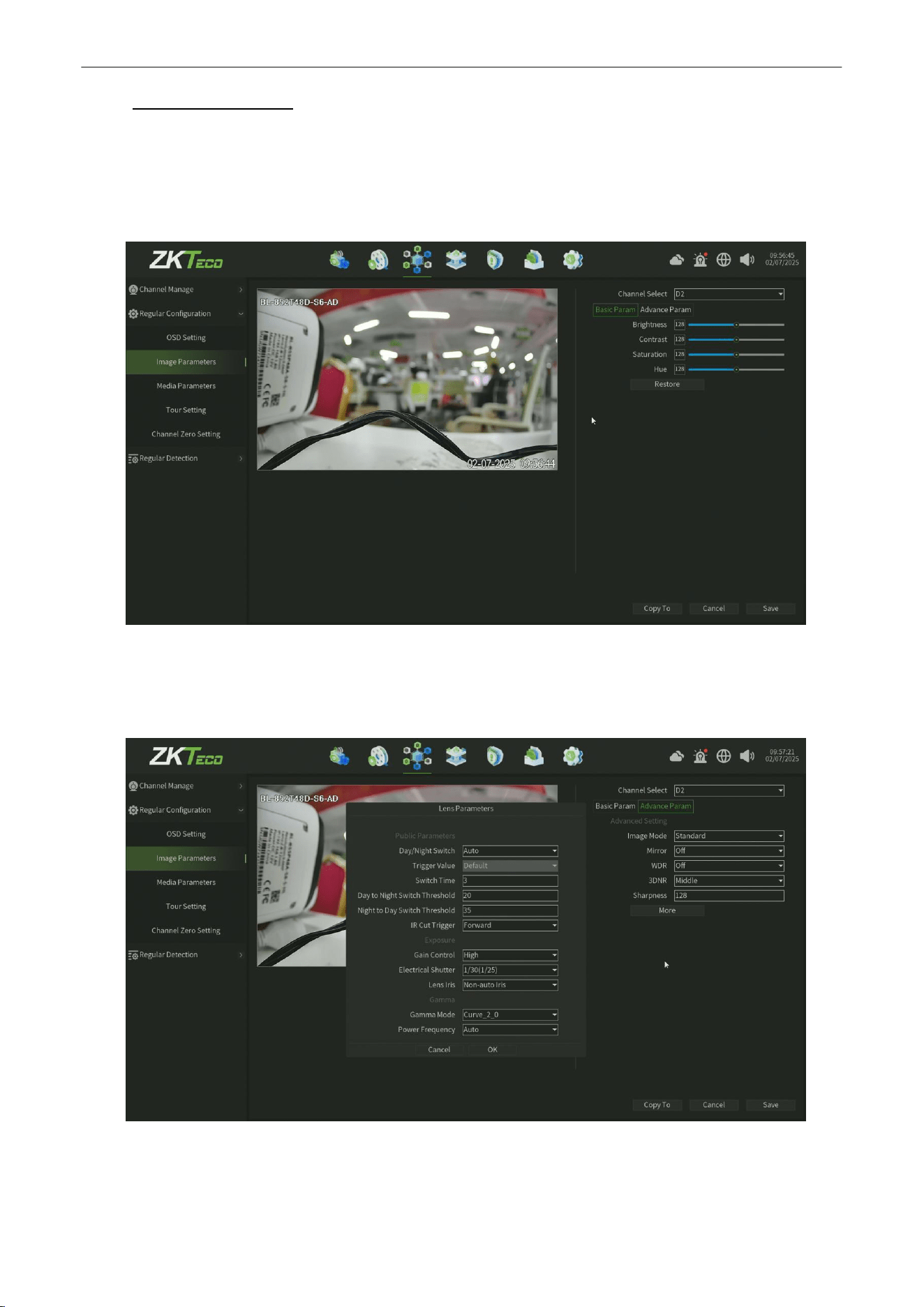
6.2.2.
Image Parameters
Purpose:
You can configure Image Parameters:
1. Basic Param:Adjust the Brightness, Contrast, Saturationand Hue ofthe channel, as shownin figure6.7.
Figure
6.7
Image Base Param Setting
2. Advance Parm: Adjust the Image Mode,Mirror,WDR,3DNR,Sharpness,Public Parameters,
Exposure,Gamma,as shown in figure 6.8.
Figure 6.8 Image Advance Param Setting
3.
Click Save button to save the settings.
Network Video Recorder
User
Manual
P a g e
|
31
Copyright©2025 ZKTECO CO., LTD. All rights reserved.
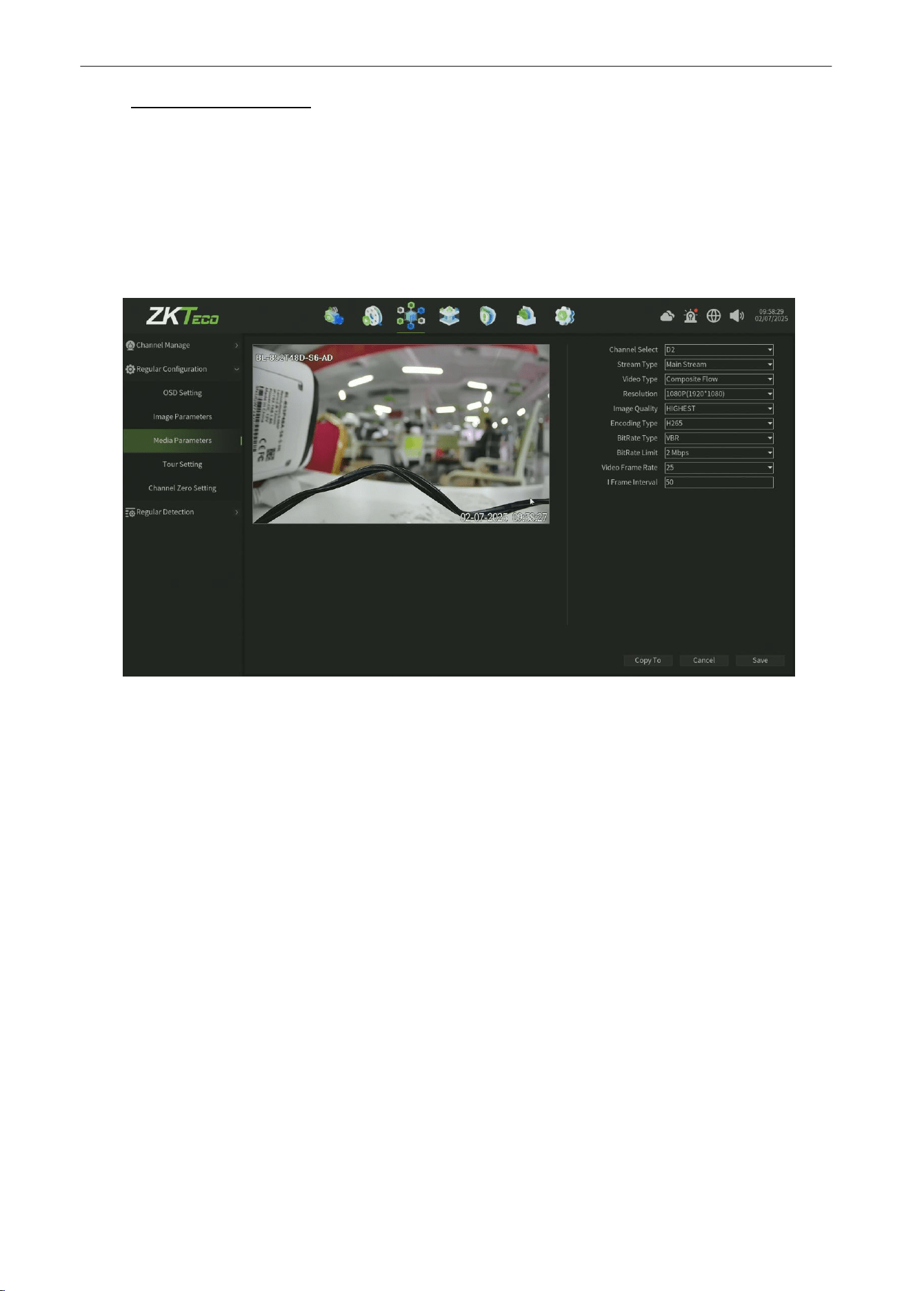
6.2.3.
Media
Parameters
Purpose:
Sometimes you need to edit the channel Camera recording parameters for better image.
Steps:
1.
Enter the media parameters interface, as shown in figure 6.9.
2.
Then you can configure the Main Stream and Second Stream or the third Stream(need supported by camera).
Figure 6.9 Media Parameter Setting
3.
Set the video parameter:
•
Channel Select:
Select the channel of camera to configure the encoding type.
• Stream Type: Select Main Stream or Sub Stream.
• Video type: Select the video type.
•
Resolution:
Select the video resolution.
• Image Quality: Select the Image quality when VBR (Variable bite rate).
• Encoding type: Select H.264 or H.265.
•
BitRate Type:
CBR & VBR can be selected.
• Bitrate Limit: Set the Bit-Rate.
•
Video Frame Rate: Select the frame rate.
•
I Frame Interal :
select the i frame interval.
4.
Click Save button to save the setting.
Network Video Recorder
User
Manual
P a g e
|
32
Copyright©2025 ZKTECO CO., LTD. All rights reserved.
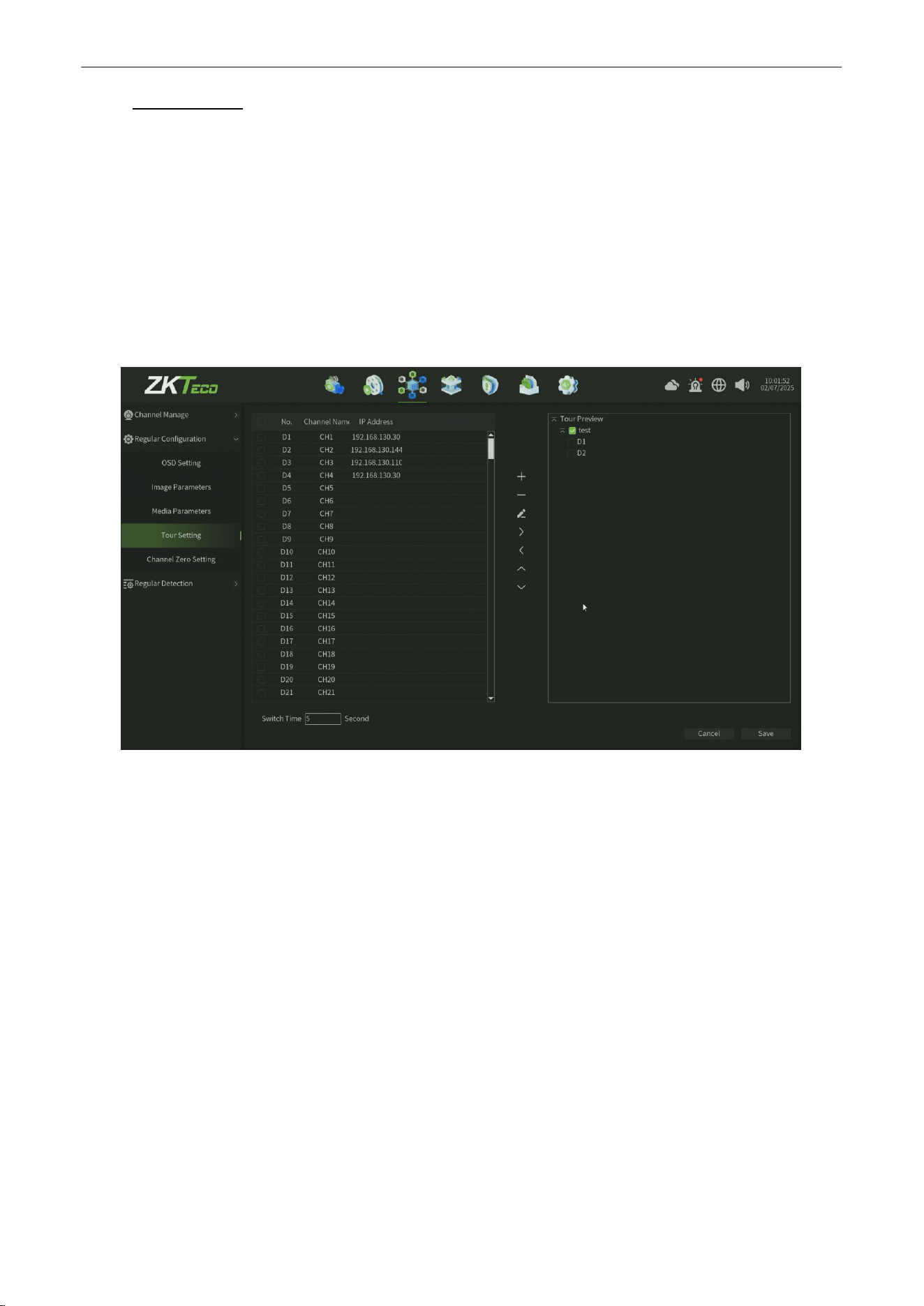
6.2.4.
Tour Setting
Purpose:
If you need to
open the Tour preview function,can configure this setting
.
Steps:
1.
Enter the
Tour Setting
interface, as shown in figure 6.10.
2.
Create
a TourPreview
Group
,then select the
channel
to the group.
3.
You can set the
Switch Time
for Tour Preview
4.
Click Save button to save the setting.
Figure 6.10 Tour Setting Interface
Network Video Recorder
User
Manual
P a g e
|
33
Copyright©2025 ZKTECO CO., LTD. All rights reserved.
6.2.5.
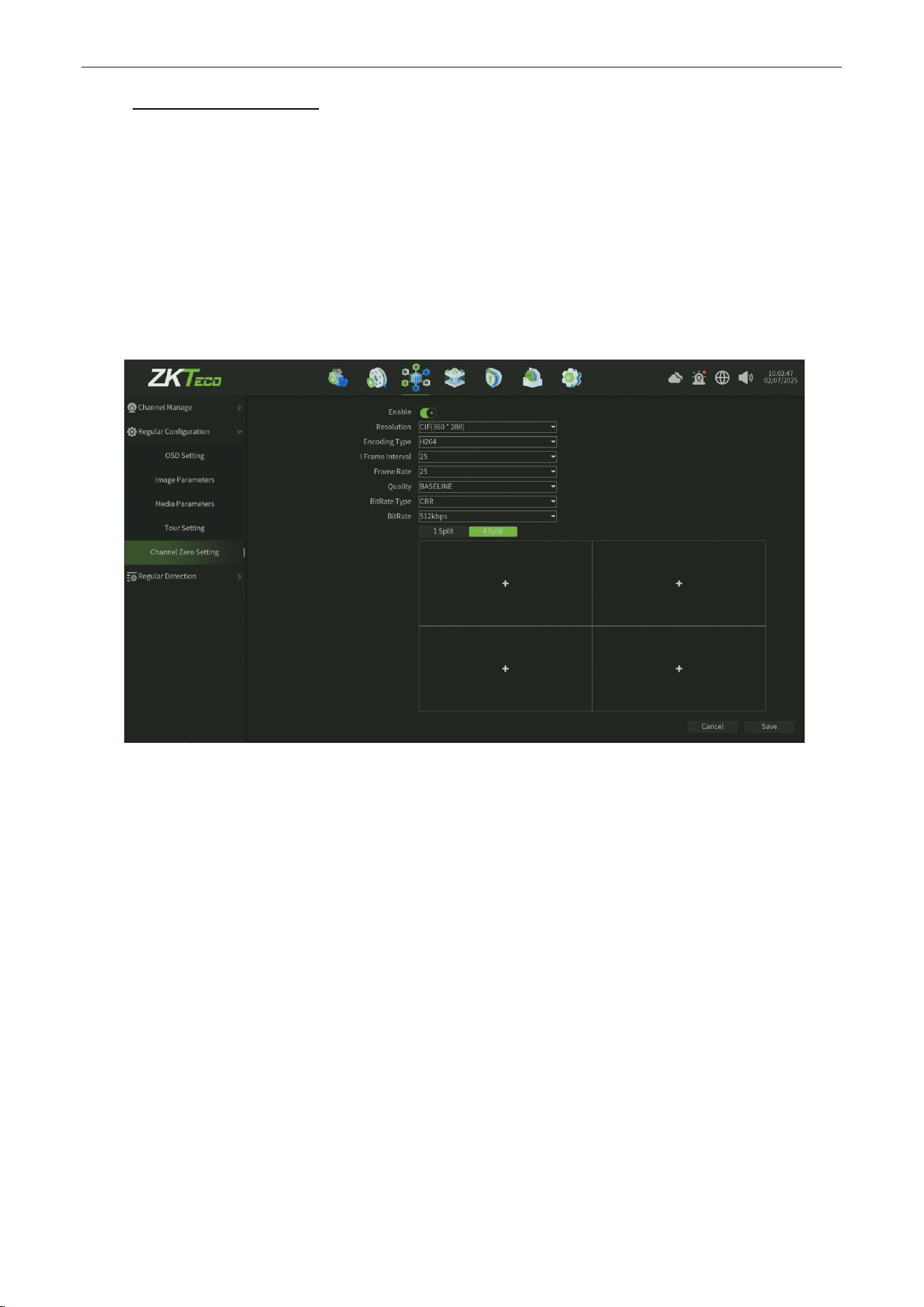
Channel Zero Setting
Purpose:
You can configure the
Channel Zero Setting
Function for the low bandwidth environmentin in this Setting page.
Steps:
1.
Enable the
Channel Zero Setting
interface, as shown in figure 6.11.
2.
Setting the Resolution,Encording Type,I Frame Interval,Frame Rate,Image Quality,BitRate Type,BitRate.
3.
You can choose the 1 split or 4 split screen.
4.
Click
Save
button to save the setting.
Figure 6.11 Channel Zero Setting
Network Video Recorder
User
Manual
P a g e
|
34
Copyright©2025 ZKTECO CO., LTD. All rights reserved.
6.3.
Regular
Detection
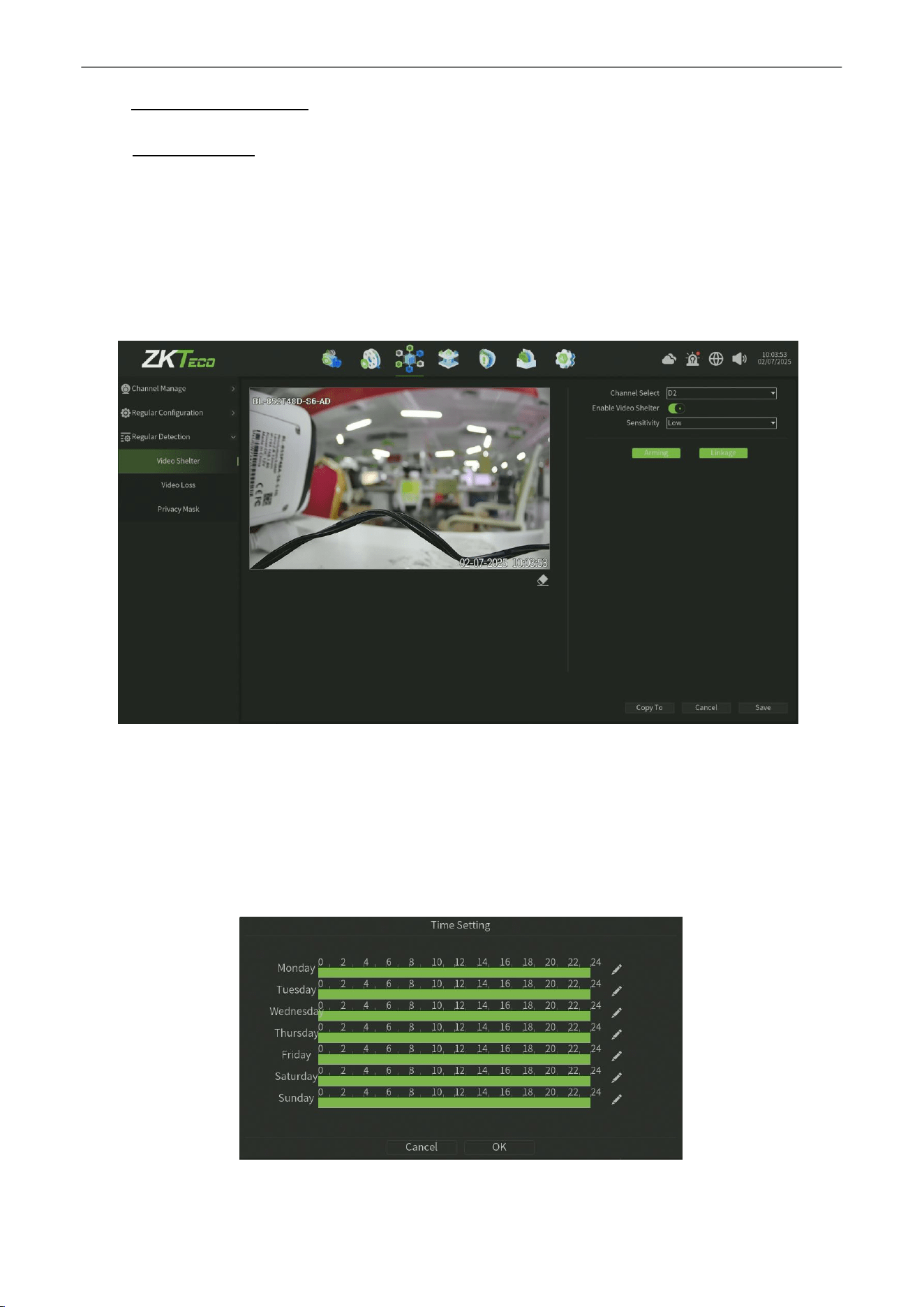
6.3.1.
Video
Shelter
Purpose:
Trigger alarm when the lens is covered and take alarm response action(s).
Steps:
1.
Enter Video Mask Alarm interface of channel parameter and choose a channel you want to setup Video Mask
Alarm, as shown in figure 6.12.
Figure6.12 Video Tampering
2.
Set the video mask alarm handling action of the channel.
1)
Check the check-box of Enable Video Shelter.
2)
Select the sensitivity.
3)
Use the mouse to draw an area you want to detect video shelter.
3.
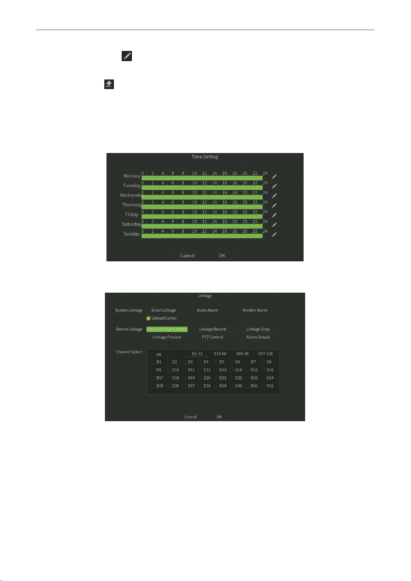
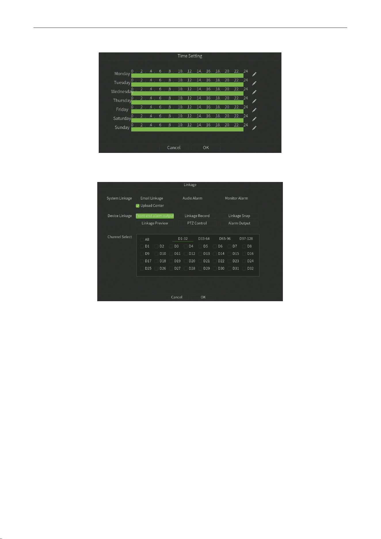
Click Arming button,Setup the Time Setting of the channel, as shown in figure 6.13.
Figure 6.13 Time Setting
Network Video Recorder
User
Manual
P a g e
|
35
Copyright©2025 ZKTECO CO., LTD. All rights reserved.
4.
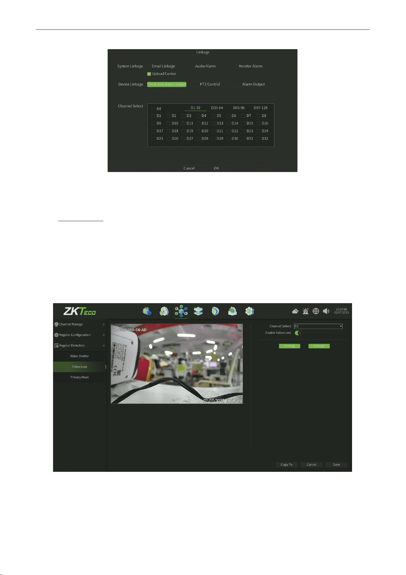
Click Linkage button,Setup the linkage operation of the function, as shown in figure 6.14.
Figure
6.14
Linkage
5.
Click Save button to save the settings.
6.3.2.
Video
Lost
Purpose:
Trigger alarm when
occur to Video Lost
.
Steps:
1.
Enter Video Lost interface of Regular Detection and select a channel you want to setup Video Lost Alarm, as shown
in figure 6.15
Figure 6.15 Video Loss
2.
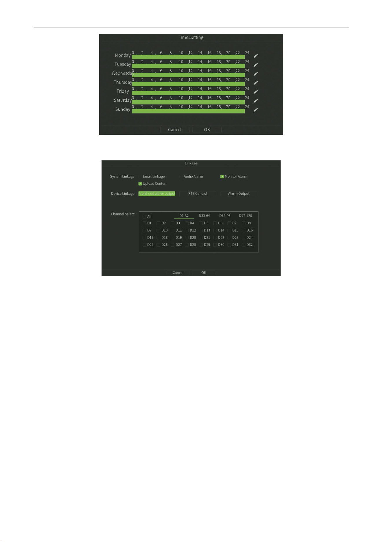
Click Arming button,Setup the Time Setting of the channel, as shown in figure 6.16.
Network Video Recorder
User
Manual
P a g e
|
36
Copyright©2025 ZKTECO CO., LTD. All rights reserved.
Figure 6.16 Time Setting
3.
Click Linkage button,Setup the linkage operation of the function, as shown in figure 6.17.
Figure
6.17
Linkage
4.
Click
Save
button to save the settings.
Network Video Recorder
User
Manual
P a g e
|
37
Copyright©2025 ZKTECO CO., LTD. All rights reserved.
6.3.3.
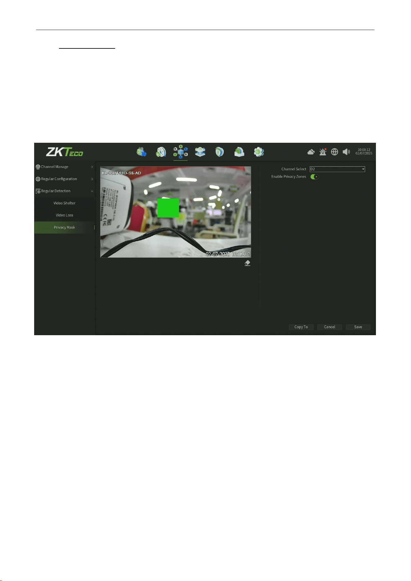
Privacy
Mask
Purpose:
Y
ou are allowed to configure the four-sided privacy mask zones that cannot be viewed by the operator. The privacy
mask can prevent certain surveillance areas to be viewed or recorded(the privacy area just display on the preview
interface,the record can not save the privacy area image).
Steps:
1.
Enter the Privacy Mask interface, as shown in figure 6.18.
Figure 6.18 Privacy Mask
2.
Select the channel to set privacy mask.
3.
Click the check-box of
Enable Privacy Zones
to enable this feature.
4.
Use the mouse to draw a zone on the window, up to 4 privacy mask zones can be configured and the size of each
area can be adjusted.
5.
Click the
Save
button to save the settings.
Note: Onvif protocol can’t support privacy mask.
Network Video Recorder
User
Manual
P a g e
|
38
Copyright©2025 ZKTECO CO., LTD. All rights reserved.
7.
Intelligence
7.1.
Intelligent Function
Smart analysis is the vital function of Intelligent NVR, and this chapter will give clear and specific instructions in terms
of intelligent performance, process and parameter configuration.
7.1.1.
Crowd Situation
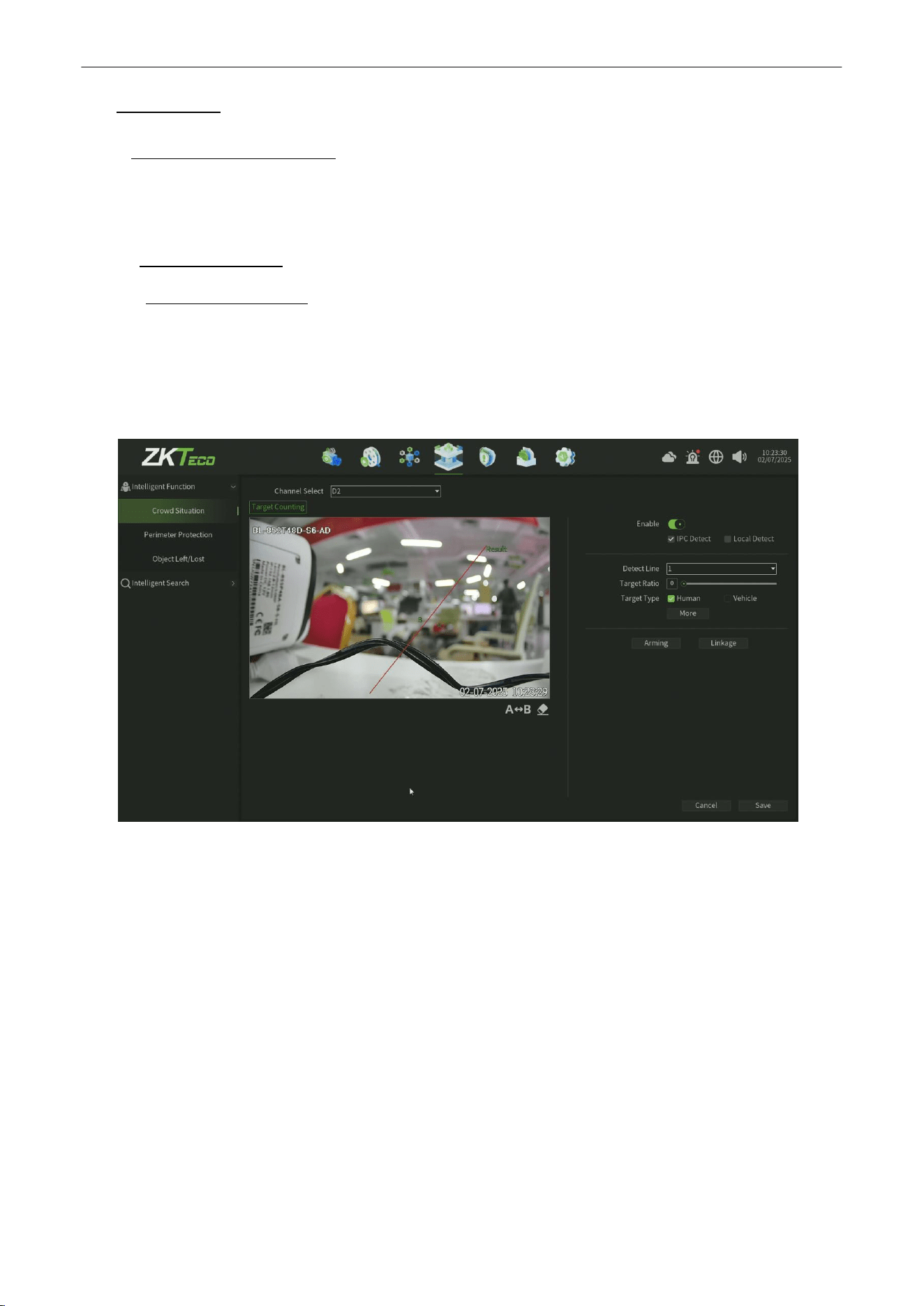
7.1.1.1.
Target
Counting
Purpose:
The purpose of this page is to configure the relevant parameters so that the target count alarm occurs when a
moving object whose proportion is larger strides the set detection line to obtain the number set by the detection
rules, as shown in figure 7.1, Thefollowing describes the parameters of the pages on the set method.
Figure7.1 Target Counting
Steps:
1. Channel Select:
Select the channel.
2.
Enable:
Check to enable the target count.
3.
Detect Mode:
The default is "IPC Detect", when NVR support smart (smart detection)can switch mode to "Local Detect".
4.
A<—>B: A / B area location on both sides of detection line can be exchanged.
5.
Detection line:
Each chan canbe set up to four detection lines, directly on the screen drag the left mouse button to
draw the line, release theleft button, right-click to complete the drawing line, the completion of the detection line on
both sides were AB Area, upper side display the statistical results.
6.
Target Ratio:
Set the proportion of the target in the whole screen, the default value is 0, which means that any
proportionwill capture the trigger and is regarded as the most accurate.
7.
Target Type:
The detection based on different algorithmsis divided into Human shape detection and Vehicle shape
detection
.
Network Video Recorder
User
Manual
P a g e
|
39
Copyright©2025 ZKTECO CO., LTD. All rights reserved.
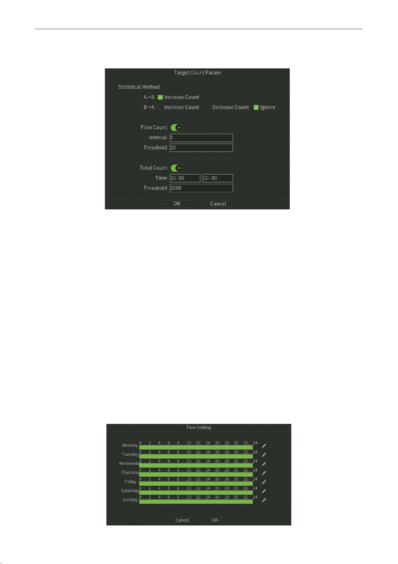
Target Count Param
The following describes the parameters of the pageson the set method. as shown in figure 7.2.
Figure 7.2 Target Count Param
8.
Statistical Method
•
A
-
> B:
Acquiesce is A area to B area to increase counting, A / B area location on both sidesof detection line
can be exchanged.
•
B->A:
Acquiesce is B area to A area to increase counting or Reduce Count or Ignore, A / B area location on
both sides of detection line can be exchanged.
9.
Flow Count:
Enable the Flow Count function,You can set an alarm to trigger when the count reaches a certain threshold
within a certain period of time
•
Interval:
Setup the detect time under the Flow Count function.
•
Threshold:
Setup the Count Threshold under the Flow Count function.
10.
Total Count:
Enable the Total Count function,You can set an alarm to be triggered when the count reaches a certain
threshold within a certain time interval
•
Time:
Setup the time Sechedule under the Flow Count function.
• Threshold:
Setup the Count Threshold under the Total Count function.
11.
Arming:
Click Arming button,Setup the Time Setting of the channel, as shown in figure 7.3.
Network Video Recorder
User
Manual
P a g e
|
40
Copyright©2025 ZKTECO CO., LTD. All rights reserved.
Figure 7.3 Time Setting
12.
Linkage:
Click Linkage button,Setup the linkage operation of the function, as shown in figure 7.4.
Figure
7.4
Linkage
13.
Save:
Click Save button to save the settings.
7.1.2.
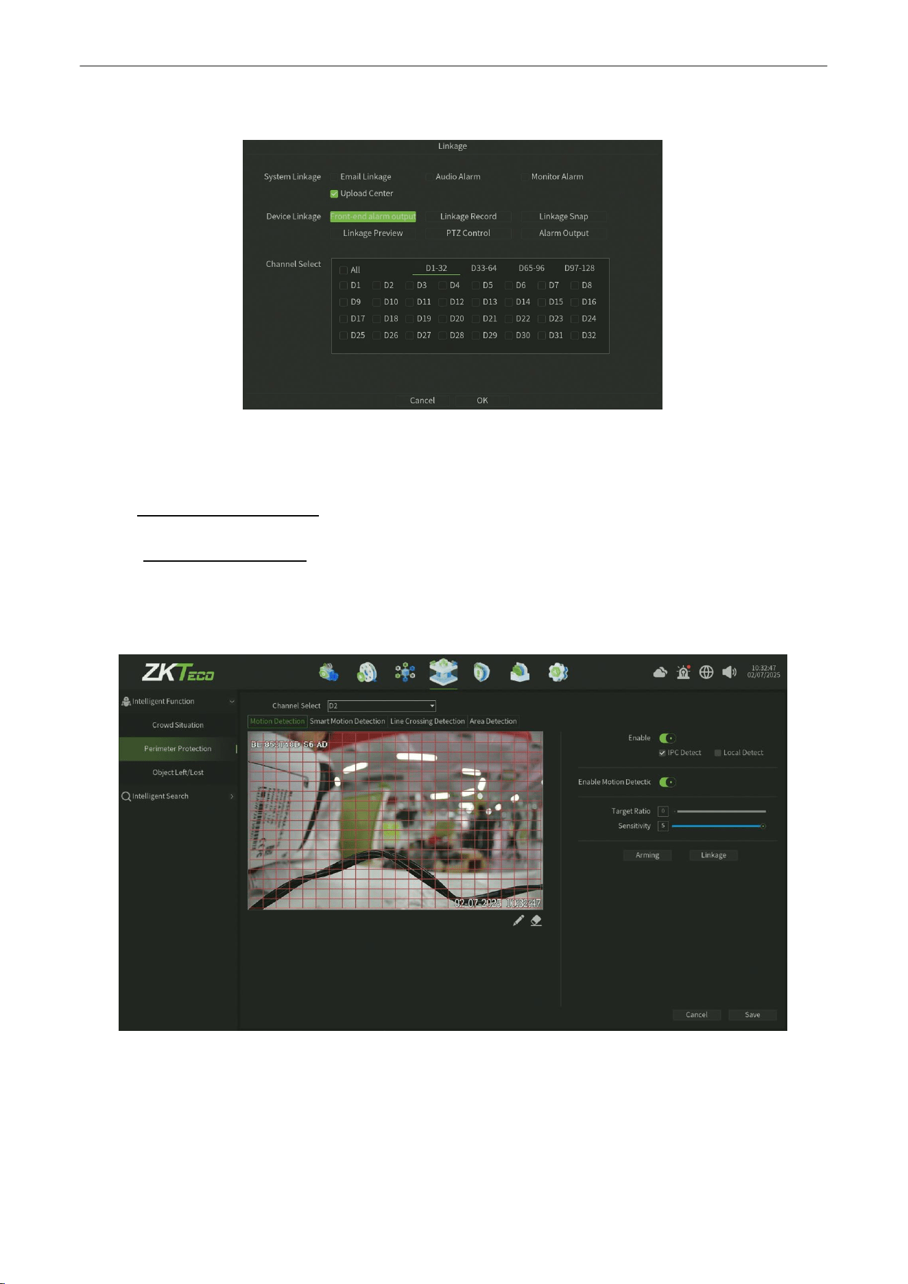
Perimeter Protection
7.1.2.1.
Motion
Detection
Purpose:
Motion detect interface is shown in figure 7.5, can set the related parameters of motion detection.
Figure 7.5 Motion Detect
Steps:
1. Channel Select:
Select the channel.
2.
Enable: Check to enable the Motion Detect.
3.
Detect Mode:
The default is "IPC Detect", when NVR support smart (smart detection)can switch mode to "Local Detect".
Network Video Recorder
User
Manual
P a g e
|
41
Copyright©2025 ZKTECO CO., LTD. All rights reserved.
4.
Enable Motion Detection Log: Check to enable the Motion Detection Log pushed.
5.
Zone setting:
One click
and h
old the left mouse button directlyin the picture, drag to the area that needs motion
detection,the red plaid area s the selected motion detection area.
6.
Clear all: Oneclick to clear the motion detect area on the screen set before.
7.
Target Ratio:
Set the proportion of the target in the whole screen, the default value is 0, which means that any
proportionwill capture the trigger and is regarded as the most accurate.
8.
Sensitivity: Canincrease the accuracyof the motion detection trigger after setting up reasonably.
9.
Arming:
Click Arming button,Setup the Time Setting of the channel, as shownin figure 7.6.
Figure 7.6 Time Setting
10.
Linkage:
Click Linkage button,Setup the linkage operation of the function, as shown in figure 7.7.
Figure
7.7
Linkage
11.
Save:
Click
Save
button to save the setting.

Network Video Recorder
User
Manual
P a g e
|
42
Copyright©2025 ZKTECO CO., LTD. All rights reserved.
7.1.2.2.
Smart Motion
Detection
Purpose:
Smart Motion detect interface is shown in figure 7.8, Different from Motion Detec
t,
it supports a Vehicle-Human
detection algorithm,can set the related parameters of motion detection.
Figure 7.8
Intelligent
Motion Detect
Steps:
1.
Channel Select:
Select the channel.
2.
Enable: Check to enable the Intelligent MotionDetect.
3.
Detect Mode:
The default is "IPC Detect", when NVR support smart (smart detection)can switch mode to "Local Detect".
4.
Enable Motion Detection Log:
Check to enable the Motion Detection Log pushed.
5.
Detect Area:
Each chan can be set up to four detection lines, directlyon the screen drag the left mouse button to draw
the line, release the left button, right-click to complete the drawing line, the completion of the detection line on both
sides were AB Area, upper side display the statisticalresults.
6.
Clear all:
One click to clear the motion detection area on the screen set before.
7.
Target Ratio:
Set the proportion of the target in the whole screen, the default value is 0, which means that any
proportionwill capture the trigger and is regarded as the most accurate.
8.
Sensitivity: Canincrease the accuracyof the motion detection trigger after setting up reasonably.
9.
Target Type:
The detection based on different algorithmsis divided into Human shape detection and Vehicle shape
detection.

Network Video Recorder
User
Manual
P a g e
|
43
Copyright©2025 ZKTECO CO., LTD. All rights reserved.
10.
Arming:
Click Arming button,Setup the Time Setting of the channel, as shownin figure 7.9.
Figure 7.9 Time Setting
11.
Linkage:
Click Linkage button,Setup the linkage operation of the function, as shown in figure 7.10.
Figure
7.10
Linkage
12.
Save:
Click
Save
button to save the setting.
Network Video Recorder
User
Manual
P a g e
|
44
Copyright©2025 ZKTECO CO., LTD. All rights reserved.
7.1.2.3.
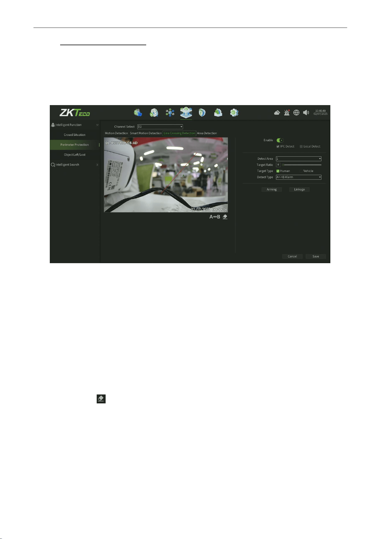
Line Crossing Detection
Purpose:
The purpose of this page is to configure the relevant parameters, so that more than the proportion of moving objects,
across the set of test lines, the virtual alarm immediately alarm line. The following describes the main parameters of the
page setting method,as shown in figure 7.11.
Figure 7.11
Tripwire
Detection
Steps:
1.
Channel Select:
Select the channel.
2.
Enable: Check to enable theTripwire Detection.
3.
Detect Mode:
The default is "IPC Detect", when NVR support smart (smart detection)can switch mode to "Local Detect".
4.
Detection Area:
Each chan canbe set up to four detection lines, directly on the screen drag the left mouse button to
draw the line, release theleft button, right-click to complete the drawing line, the completion of the detection line on
both sides were AB Area, upper side display the statistical results.
5.
A<—>B: A / B area location on both sides of detection line can be exchanged.
6.
Clear all:
One click to clear the motion detection area on the screen set before.
7.
Target Ratio:
Set the proportion of the target in the whole screen, the default value is 0, which means that any
proportionwill capture the trigger and is regarded as the most accurate.
8.
Target Type:
The detection based on different algorithmsis divided into
Human
shape detection and
Vehicle
shape
detection.
9.
DetectType:
There are two types: "A-> B Alarm" and "A <-> B Alarm"
.

Network Video Recorder
User
Manual
P a g e
|
45
Copyright©2025 ZKTECO CO., LTD. All rights reserved.
10.
Arming:
Click Arming button,Setup the Time Setting of the channel, as shownin figure 7.12.
Figure 7.12 Time Setting
11.
Linkage:
Click Linkage button,Setup the linkage operation of the function, as shown in figure 7.13.
Figure
7.13
Linkage
12.
Save:
Click Save button to save the setting.
Network Video Recorder
User
Manual
P a g e
|
46
Copyright©2025 ZKTECO CO., LTD. All rights reserved.
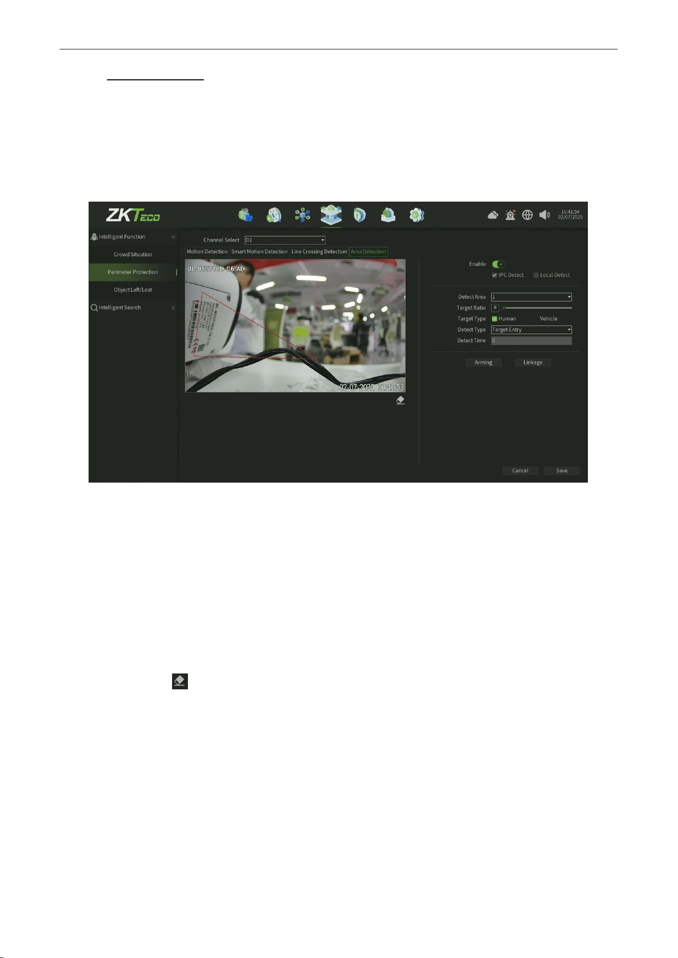
7.1.2.4.
Area Detection
Purpose:
The purpose of this page is to configure the relevant parameters, so that more than the proportion of moving objects,
enter / leave / hovering in the set detection area, over time detection zone detection alarm occurs, the following page
describes the main parameters of the setting method,as shown in figure 7.14.
Figure
7.14 Area Detection
Steps:
1. Channel Select:
Select the channel.
2.
Enable: Check to enable the Area Detect.
3.
Detect Mode:
The default is "IPC Detect", when NVR support smart (smart detection)can switch mode to "Local Detect".
4.
Detection Area:
Each chan canbe set up to four detection lines, directly on the screen drag the left mouse button to
draw the line, release theleft button, right-click to complete the drawing line, the completion of the detection line on
both sides were AB Area, upper side display the statistical results.
5.
Clear all:
One click to clear the motion detection area on the screen set before.
6.
Target Ratio: Set the proportion of the target in the whole screen, the default value is 0, which means that any
proportionwill capture the trigger and is regarded as the most accurate.
7.
Target Type:
The detection based on different algorithmsis divided into
Human
shape detection and
Vehicle
shape
detection.
8.
DetectType:
There are "Target Entry", "Target Leave", "Target Entry or Leave", "target Loiter" 4.
9.
Detect Time:
Set the Detect time for Target Loiter function Detect Type.

Network Video Recorder
User
Manual
P a g e
|
47
Copyright©2025 ZKTECO CO., LTD. All rights reserved.
10.
Arming:
Click Arming button,Setup the Time Setting of the channel, as shownin figure 7.15.
Figure 7.15 Time Setting
11.
Linkage:
Click Linkage button,Setup the linkage operation of the function, as shown in figure 7.16.
Figure
7.16
Linkage
12.
Save:
Click Save button to save the setting
Network Video Recorder
User
Manual
P a g e
|
48
Copyright©2025 ZKTECO CO., LTD. All rights reserved.
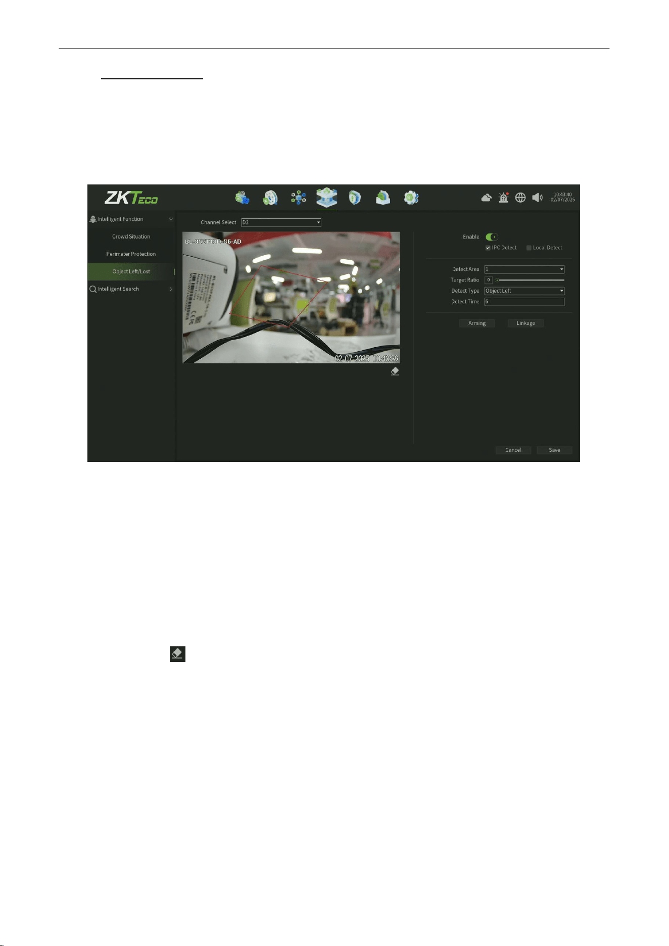
7.1.3.
Object Left/Lost
Purpose:
The purpose of this page is to configure the relevant parameters, so that more than the proportion of objects in the set
detection area lost / left over time detection time that goods detection alarm, the following describes the main parameters
on the page set method, As shown in figure 7.17.
Figure 7.17
Object Left/Lost
Steps:
1.
Channel Select:
Select the channel.
2.
Enable: Check to enable the Object Left/Lost functiont.
3.
Detect Mode:
The default is "IPC Detect", when NVR support smart (smart detection)can switch mode to "Local Detect".
4.
Detection Area:
Each chan canbe set up to four detection lines, directly on the screen drag the left mouse button to
draw the line, release theleft button, right-click to complete the drawing line, the completion of the detection line on
both sides were AB Area, upper side display the statistical results.
5.
Clear all: Oneclick to clear the motion detection area on the screen set before.
6.
Target Ratio: Set the proportion of the target in the whole screen, the default value is 0, which means that any
proportionwill capture the trigger and is regarded as the most accurate.
7.
DetectType:
There are "Object
L
ost", "Object
L
eft", "Object
L
ost or Left" three types.
8.
Detect Time:
Set the Detect time for different Detect Types.
Network Video Recorder
User
Manual
P a g e
|
49
Copyright©2025 ZKTECO CO., LTD. All rights reserved.
9.
Arming:
Click Arming button,Setup the Time Setting of the channel, as shownin figure 7.18.
Figure 7.18 Time Setting
10.
Linkage:
Click Linkage button,Setup the linkage operation of the function, as shown in figure 7.19.
Figure
7.19
Linkage
11.
Save:
Click Save button to save the setting.
Network Video Recorder
User
Manual
P a g e
|
50
Copyright©2025 ZKTECO CO., LTD. All rights reserved.
7.2.
Intelligent Search
7.2.1.
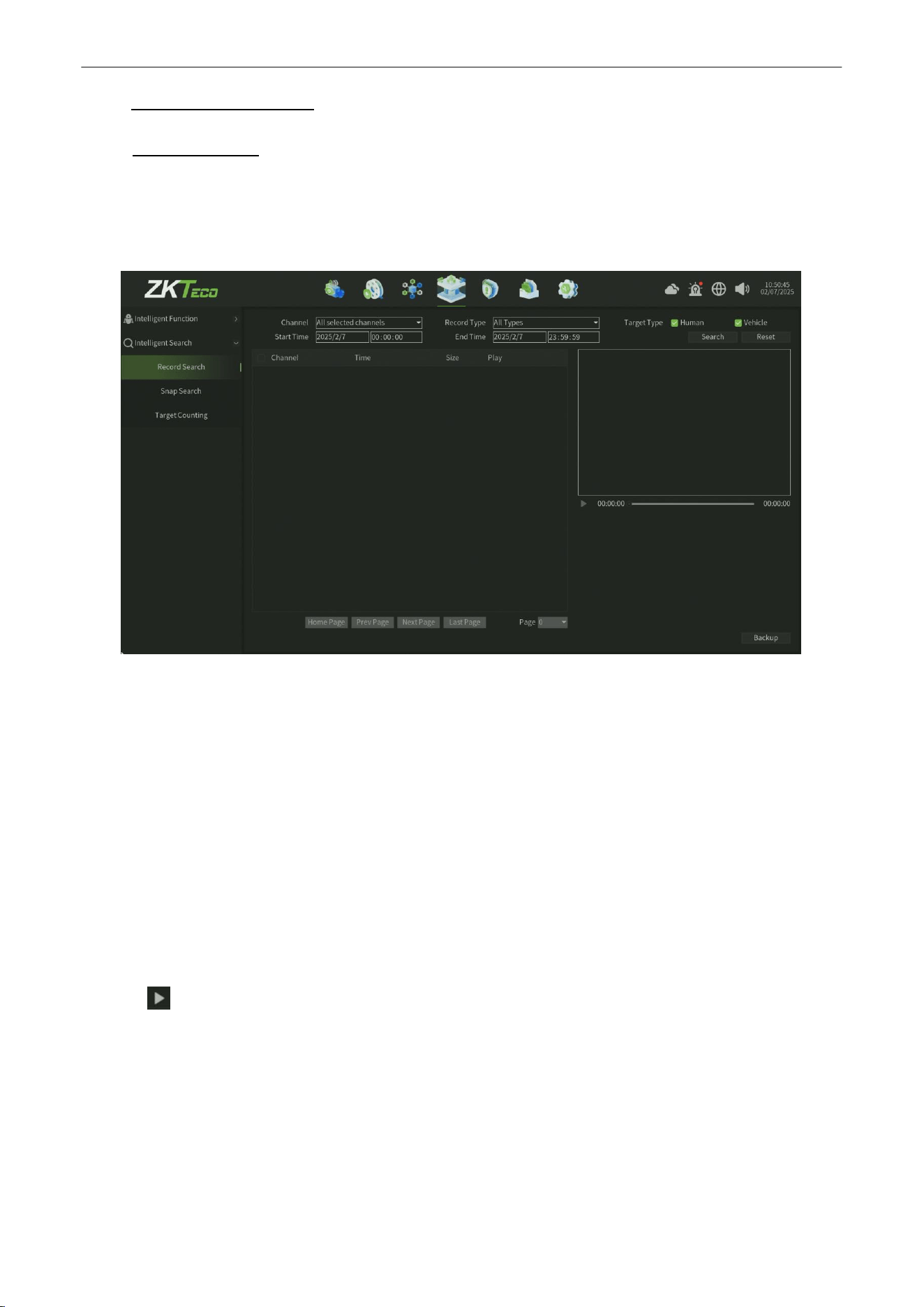
Record Search
Purpose:
If you want to find the different type record under the specific date,Search the Record in this interface,and the record
files can be backup to various devices, such as USB devices (USB flash drives, USB HDDs),as shown in figure 7.20.
Figure
7.20
Record Search
Steps:
1.
Select the Channel for Record Search and Backup.
2.
Select the
Record Type
.
3.
Set the Start Time andEnd Time.
4.
Select Target Type:Human ,Vehicle Type optional
5.
Click Search button to find records and you can view the record on the right window.
6.
Click Reset button can back to the default parameter of this interface.
7.
Click button can online view the record file.
Network Video Recorder
User
Manual
P a g e
|
51
Copyright©2025 ZKTECO CO., LTD. All rights reserved.
8.
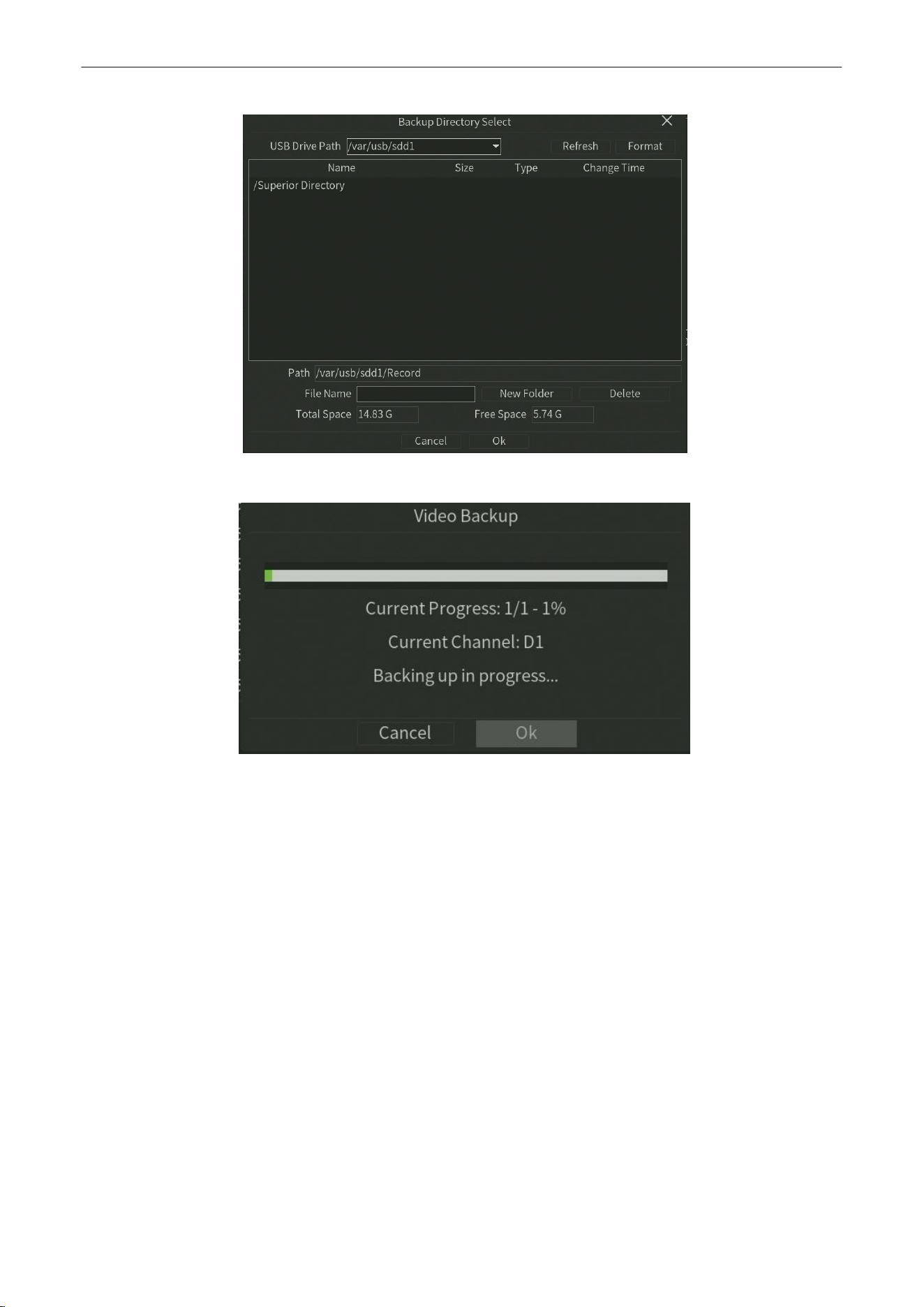
Click Backup button to start the backup(Note need plug the USB disk),as shown in figure 7.21 and 7.22.
Figure
7.21
Record Backup Setting
Figure
7.22
Record Backup
Network Video Recorder
User
Manual
P a g e
|
52
Copyright©2025 ZKTECO CO., LTD. All rights reserved.
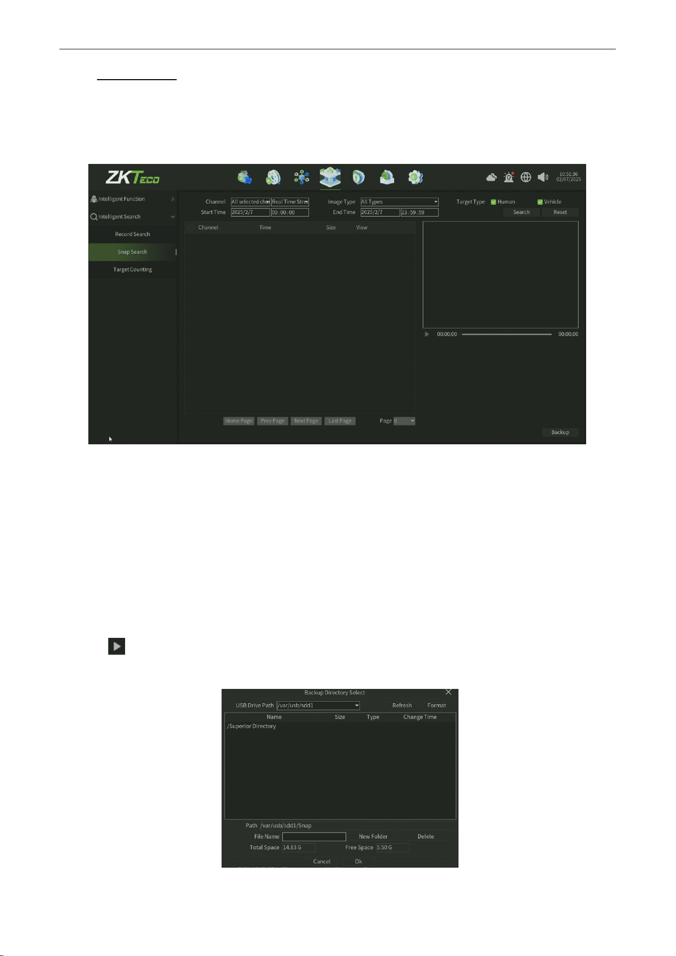
7.2.2.
Snap Search
Purpose:
If you want to find the capture image under the specific date,Search the capture image in this interface,and the capture
files can be backup to various devices, such as USB devices (USB flash drives, USB HDDs),as shown in figure 7.23.
Figure
7.23
Snap Search
Steps:
1.
Select the
Channel
for image Search and Backup.
2.
Select the
ImageType
.
3.
Set the Start Time and End Time.
4.
Select Target Type:Human ,Vehicle Type optional
5.
Click
Search
button to find image.
6.
Click Reset button can back to the default parameter of this interface.
7.
Click button can online view the record around the capture time(only 30 seconds ).
8.
Click
Backup
button to start the backup(Note need plug the USB disk),as shown in figure 7.24 and 7.25.
Figure
7.24
Snap Image Backup Setting
Network Video Recorder
User
Manual
P a g e
|
53
Copyright©2025 ZKTECO CO., LTD. All rights reserved.
7.2.3.
Target Counting
Purpose:
If you want to statistics the Target Counting under the specific date and optional Line,Statisitics the Target
Count in this interface,and the data files can be export to various devices, such as USB devices (USB flash drives,
USB HDDs),as shown in figure 7.26.
Figure
7.26
Target Count Statistics
Steps:
1.
Select the Channel for Target Count Staticstics and Export.
2.
Select
Target Type
:Human ,Vehicle Type optional
3.
Select the
Statistical Type:
. Inquire By Day,Inquire By Week,Inquire By Month,Inquire By Year
4.
Select
Target Line
: Optional Line 1,Line 2,Line 3,Line 4.
5.
Set the Statistical Time.
6.
Click Statistics button to view Target Count data form.
7.
Click Export button can export theTarget Count data(Note need plug the USB disk),as shown in figure 7.27 and 7.28.
Figure
7.27
Target Count Statistics
Network Video Recorder
User
Manual
P a g e
|
54
Copyright©2025 ZKTECO CO., LTD. All rights reserved.
8. Alarm
8.1.
Alarm Abnormal
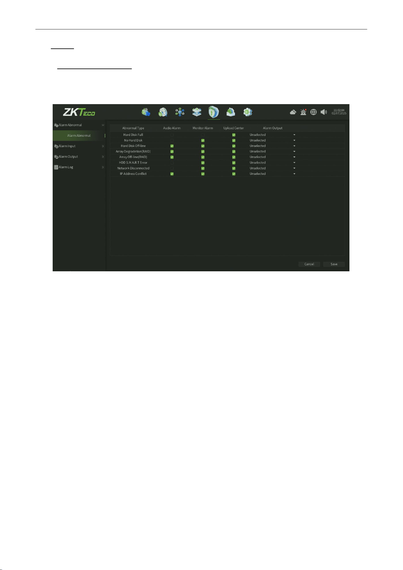
The Alarm Abnormal interface,you can enable the alarm different mode for different Abnormal event, as shown in
figure 8.1.
Figure 8.1 Alarm Abnormal Interface
Parameter:
1.
Abormal Type: Fixed Abnormal event type for system configuration,such as Hard Disk Full,No Hard Disk.
2.
Audio Aarm : Enable this alarm type,when the corresponding Abnormal event trigger, Device will give an audible
alarm.
3.
Monitor Alarm :
Enable this alarm type,when the corresponding Abnormal event trigger, Alarm information will
be pushed in the preview alarm pop-up window.
4.
Upload Center:
Enable this alarm type,when the corresponding Abnormal event trigger, Alerts go to a queue of
messages that can be pushed or pulled by other platforms.
5.
Alarm Output : Enable this alarm type,when the corresponding Abnormal event trigger, The alarm effect is
triggered by an external alarm device.
Network Video Recorder
User
Manual
P a g e
|
55
Copyright©2025 ZKTECO CO., LTD. All rights reserved.
8.2.
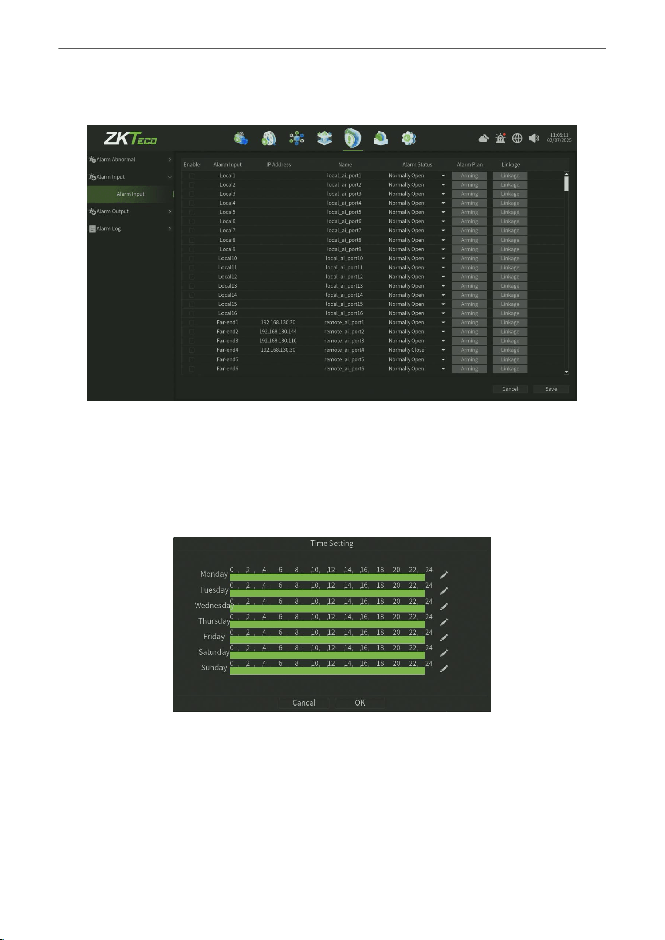
Alarm Input
The Alarm input interface, as shown in figure 8.2.
Figure
8
.2 Alarm Input Interface
Parameter:
1.
Alarm Input :
Select channel
2.
Alarm Input Name:
Edit alarm name.
3.
Alarm Status:
Set the alarm state, the default value is always open.
4.
Arming Planning: Set the arming schedule, as shown in figure 8.2.1.
Figure 8.2.1 Arming Schedule
Network Video Recorder
User
Manual
P a g e
|
56
Copyright©2025 ZKTECO CO., LTD. All rights reserved.
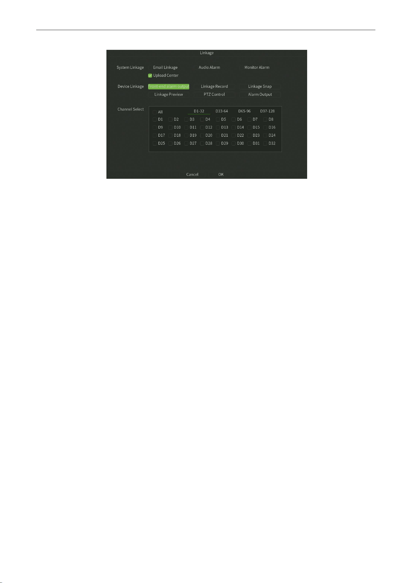
5. Linkage
: Click Linkage button,Setup the linkage operation of the function, as shown in figure 8.2.2.
Figure 8.2.2 Arming Schedule
6.
Save
: Click Save button to save the setting.

Network Video Recorder
User
Manual
P a g e
|
57
Copyright©2025 ZKTECO CO., LTD. All rights reserved.
8.3.
Alarm
Output
The Alarm input interface, as shown in figure 8.3.
Figure12.5 Alarm Output
Parameter:
1.
Alarm Output : Edit alarm name.
2.
Alarm Output Delay:Edit alarm output delay.
3.
Arming Time:
Set the arming schedule.
4. Save
: Click Save button to save the setting.
Network Video Recorder
User
Manual
P a g e
|
58
Copyright©2025 ZKTECO CO., LTD. All rights reserved.
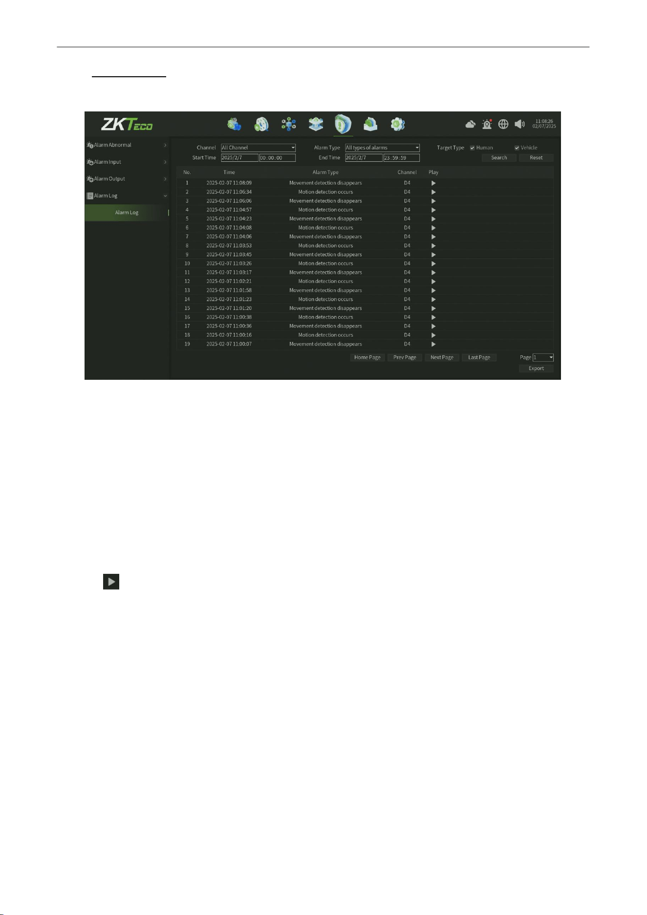
8.4.
Alarm Log
The Alarm Log interface,you can Seach the different alarm event log in this interface, as shown in figure 8.4.
Figure 8.1 Alarm Log Interface
Steps:
1.
Select the Channel for Alarm Log Search.
2.
Select the
Alarm Type,
Such as
All types of alarms
,
Video loss alarm occurs
.
3.
Set the
Start Time
and
End Time
.
4.
Select the Targrt Type : Human ,Vehicle Type optional.
5.
Click Search button to find records and you can view the record on the right window.
6.
Click Reset button can back to the default parameter of this interface.
7.
Click button can online view the record file.
8.
Click Export button can export the Alarm data(Note need plug the USB disk)
Network Video Recorder
User
Manual
P a g e
|
59
Copyright©2025 ZKTECO CO., LTD. All rights reserved.
9.
Storage
Manage
9.1.
Disk Manage
9.1.1.
Disk Configuration
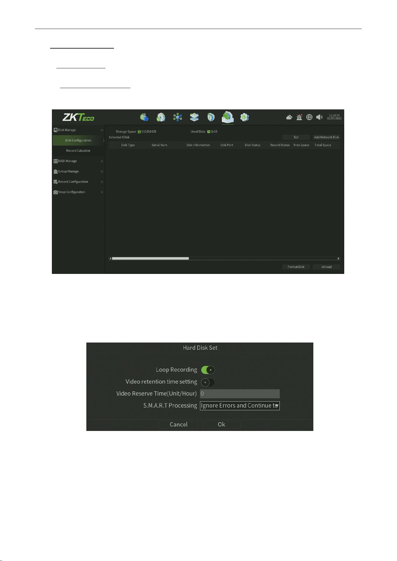
The Disk Config interface,you can view the disk status and set the disk configuration, as shown in figure 9.1.1.1.
Figure 9.1.1.1 Disk Config
Parameter:
1.
Storage Space : Display the total space and used sapce.
2.
Used Slot : Display the total slot count and used slot count.
3.
Set :
Set disk storage mode and stragety ,as shown in figure 9.1.1.2.
Figure 9.1.1.2 Disk Set
Loop Recording :
One click enable Loop Recording configuration.
Video retention time setting : One click enable the setting of video retention.
Video Reserve Time : After enable the video retention time setting option,you can set the specific reserve time of
video retention.
S.M.A.R.T Processing :
Set the smart process of the storage abnormal status.
Network Video Recorder
User
Manual
P a g e
|
60
Copyright©2025 ZKTECO CO., LTD. All rights reserved.
4.
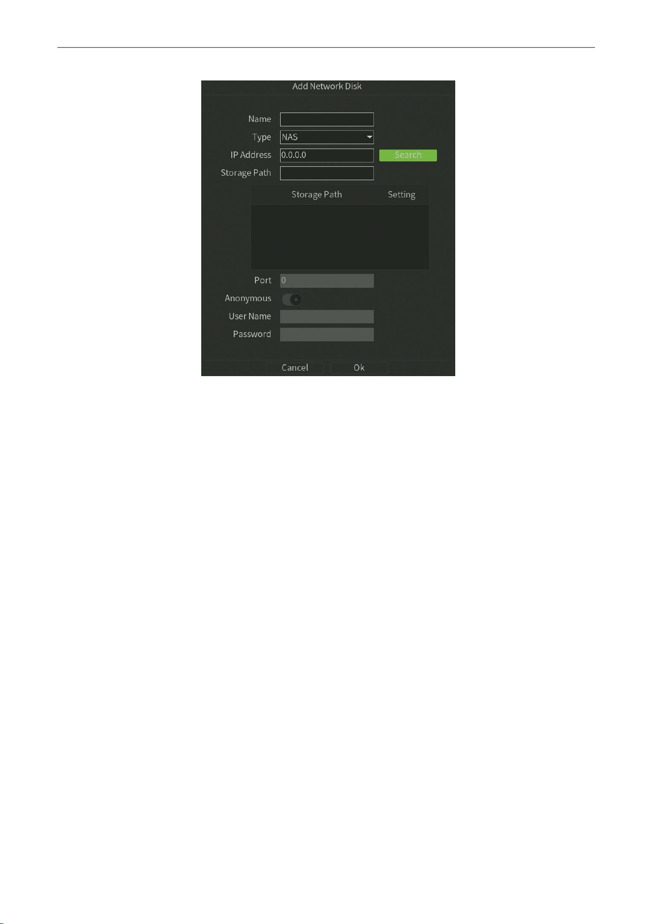
Add network disk : Manaully add the network disk ,such NAS server or IPSAN server,as shown in figure 9.1.1.3.
Figure 9.1.1.3 Add network disk
Name : Customize the network disk name.
Type : Select the network disk type (NAS and IPSAN optionally).
IP Address :
Enter into the network disk server ip address,also you can click the serach button to search the network
disk server which in the same local network and one-click get the server information .
Storage Path :
Set and select the directory of folders to store in.
Port :
Automatiacally get the server port.
Anonymous : One click enable the anonymous configuration.
User Name :
Enter the network disk server user name.
Password : Enter the network disk server password.
5.
Disk Type : Display the disk type information.
6.
Serial Num :
Display the disk Serial number information.
7.
Disk Information : Display the disk basic information.
8.
Disk Port :
Display the disk port information.
9.
Disk Status :
Display the disk status information.
10.
Record Status : Display the record status information.
11.
Free Space : Display the disk free space information.
12.
Total Space :
Display the disk total space information.
13.
Format Disk : Select the Hard disks,and then click the Format Disk button to format the corresponding disk ( note:
the first time plug the disk need to do the format disk operation ) .
14.
Unload :
Select the Hard disks,and then click the Unload button to unload the corresponding disk
Network Video Recorder
User
Manual
P a g e
|
61
Copyright©2025 ZKTECO CO., LTD. All rights reserved.
9.1.2.
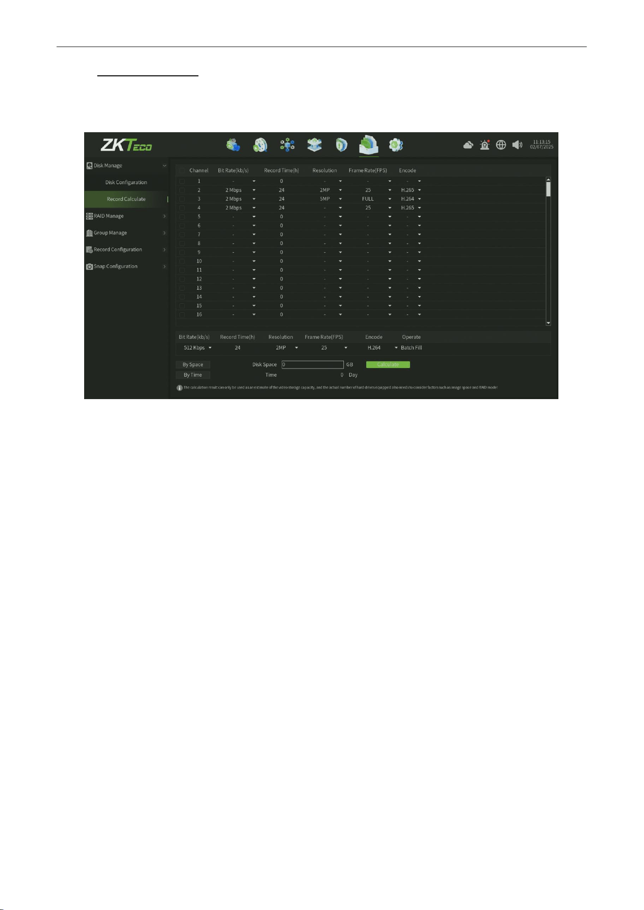
Record Calculate
The Record Calculate interface,display the total channel bitrate,record time,resolution,frame rate and encode format
information. you can calculate the record space in this interface , as shown in figure 9.1.2.1.
Figure 9.1.2.1 Record Calculate
Parameter:
1.
By Space :
Calculate the time can storage on the base of disk space.
2.
By Time : Calculate the disk space on the base of the time you wanna storage .
3.
Calculate :
One click to calculate the value by space mode or by time mode.
Note:
The calculation result can only be used as an estimate of the video storage capacity,and the actual number of hard drives
equipped also needs to consider factors such as image space and RAlD mode!
Network Video Recorder
User
Manual
P a g e
|
62
Copyright©2025 ZKTECO CO., LTD. All rights reserved.
9.2.
RAID Manage
9.2.1.
Disk RAID
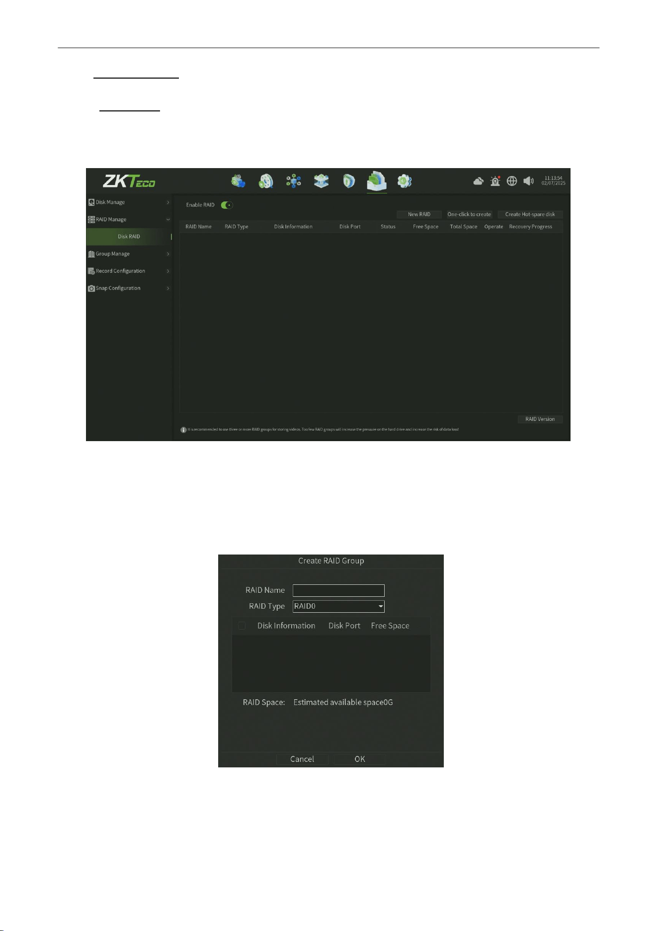
The Disk RAID interface,you can view the Disk RAID group status and set the disk RAID configuration, as shown in figure
9.2.1.1.
Figure 9.2.1.1 Disk RAID
Parameter:
1.
Enable RAID : One click enable the Disk RAID configuration,will make the device reboot.
2.
New RAID :
Create a new RAID group,and you can set the specofic RAID type and parameter ,as shown in figure
9.2.1.2.
Figure 9.2.1.2 Create RAID Group
RAID Name :
Customize the RAID group name.
RAID Type : Select the RAID type (RAID0,RAID1,RAID5,RAID6,RAID10 optionally ).
Disk Information :
Select the disks according to the RAID type to combine the RAID group.
Network Video Recorder
User
Manual
P a g e
|
63
Copyright©2025 ZKTECO CO., LTD. All rights reserved.
3.
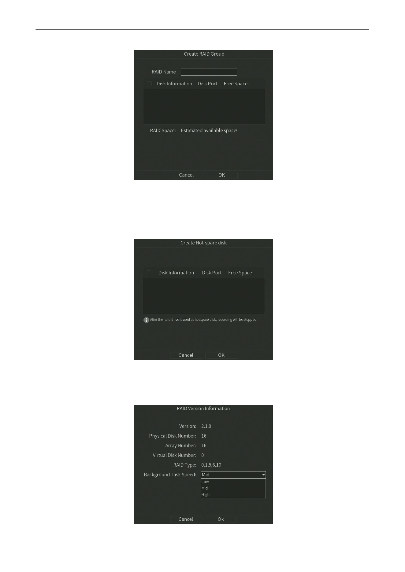
Once Create RAID : Once create a new RAID group ,as shown in figure 9.2.1.3.
Figure 9.2.1.3 Once Create RAID
RAID Name : Customize the RAID group name.
Disk Information : Select the disks according to the RAID type to combine the RAID group.
4.
Create Hot-Spare Disk :
Once create a new Hot-backup disk ,as shown in figure 9.2.1.4.
Figure 9.2.1.4 Create Hot-backup Disk
Disk Information :
Select the disks according to the RAID type to combine the RAID group.
5.
RAID Version : Display the RAID Version information,as shown in figure 9.2.1.5.
Figure 9.2.1.5 RAID Version
Network Video Recorder
User
Manual
P a g e
|
64
Copyright©2025 ZKTECO CO., LTD. All rights reserved.
9.3.
Group Manage
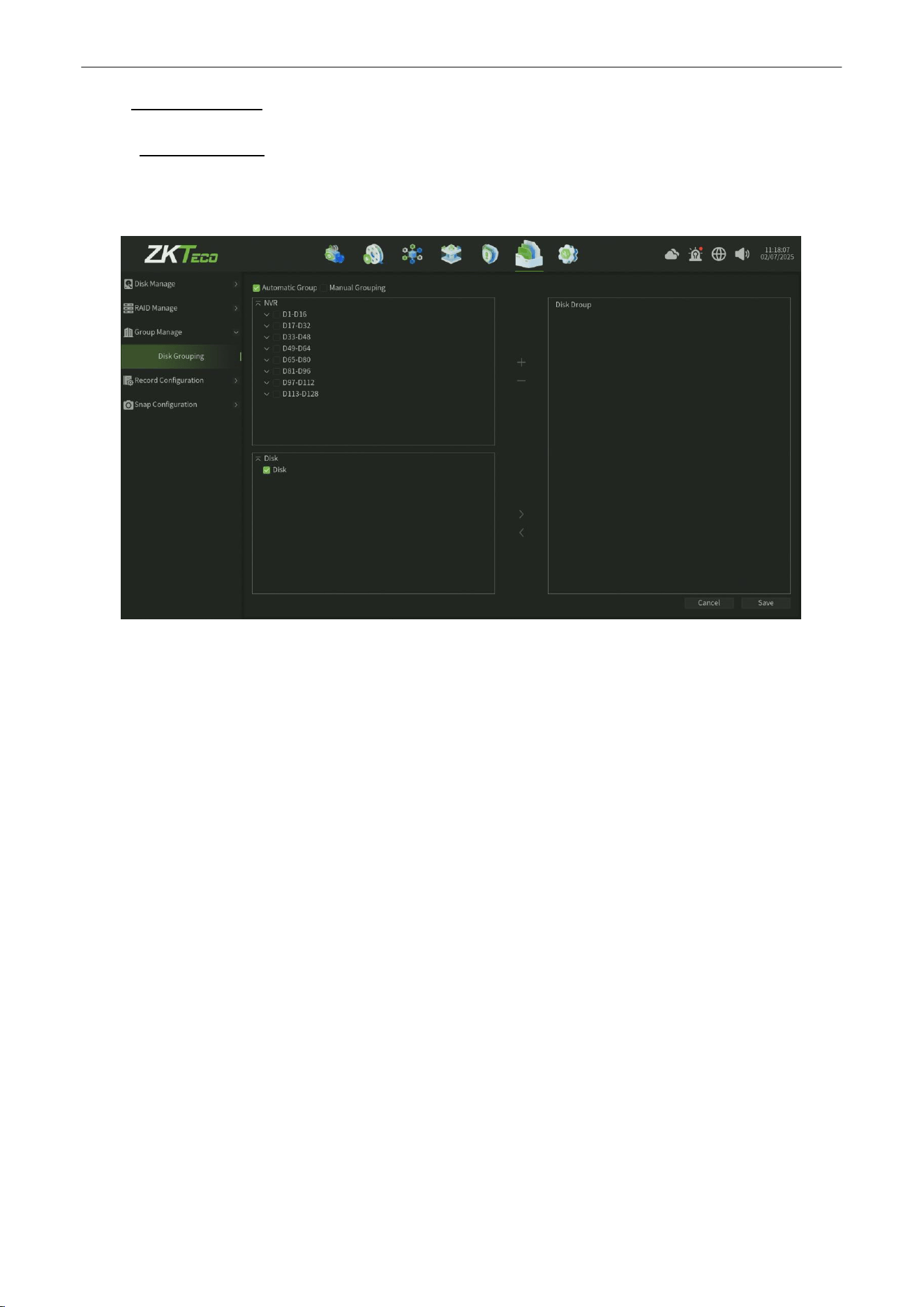
9.3.1.
Disk Grouping
The Disk Grouping interface,you can view the Disk grouping status and manaully or automatic set the disk gouping
configuration, as shown in figure 9.3.1.1.
Figure 9.3.1.1 Disk Grouping
Parameter:
1.
Automatic Group : When you check this option,it will automatic distribute channels to the disk in a group.
2.
Manaul grouping :
When you check this option,you need manaully to create a group then add a disk to this
group ,finally select channels in this group( suggestion that one disk be distribted 12-14 channels will be better ).
3.
Click Save button to save the settings.
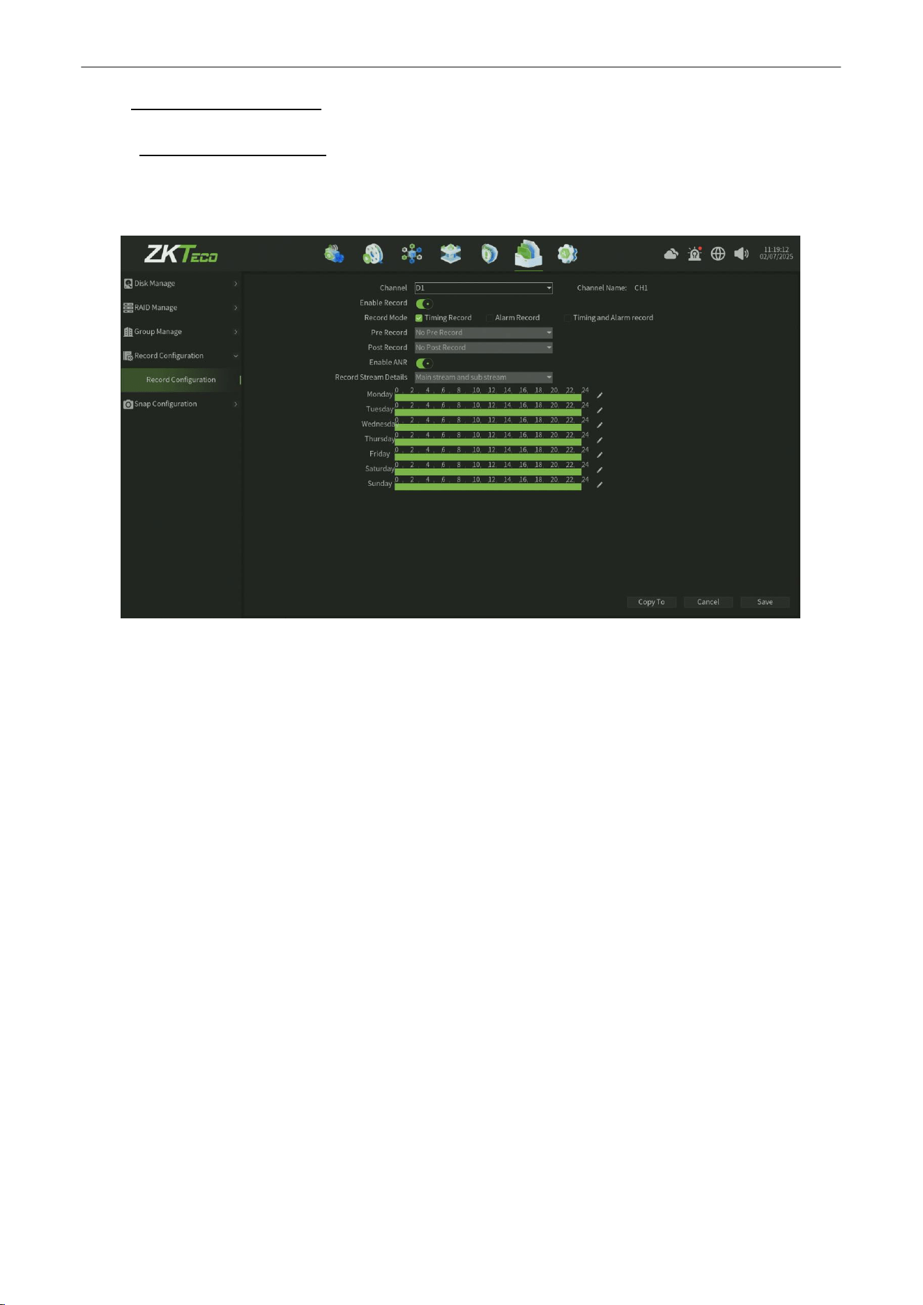
Network Video Recorder
User
Manual
P a g e
|
65
Copyright©2025 ZKTECO CO., LTD. All rights reserved.
9.4.
Record Configuration
9.4.1.
Record Configuration
The Record Configuration interface,you can set the record plan and record format configuration, as shown in figure
9.4.1.1.
Figure 9.4.1.1 Record Config
Parameter:
1. Channel :
Select the channel.
2.
Enable Record : Check to enable the Channel record.
3.
Record Mode :
Select the record mode (Time recording,Alarm recording,Time andAlarm recording three modes
optionally).
4.
Pre Record : After check the Alarm recording or Time and Alarm recording mode,you can set the Pre Record time
parameter.
5.
Post Record : After check the Alarm recording or Time and Alarm recording mode,you canset the Post Record time
parameter.
6.
Enable ANR :
When enable ANRinterface , the channel record file will recover storage in disk after the camera revover
the network connect with NVR.
7.
Record Stream Details :
The default record stream value is Main Stream and Sub Stream, cannot be modify.
8.
Schedule :
You can set the record schedule time on the schedule form.
9.
Copy to: Click the copy to button and select the specific or allchannels to copy the record configuration.
10.
Click Save button to save the settings.
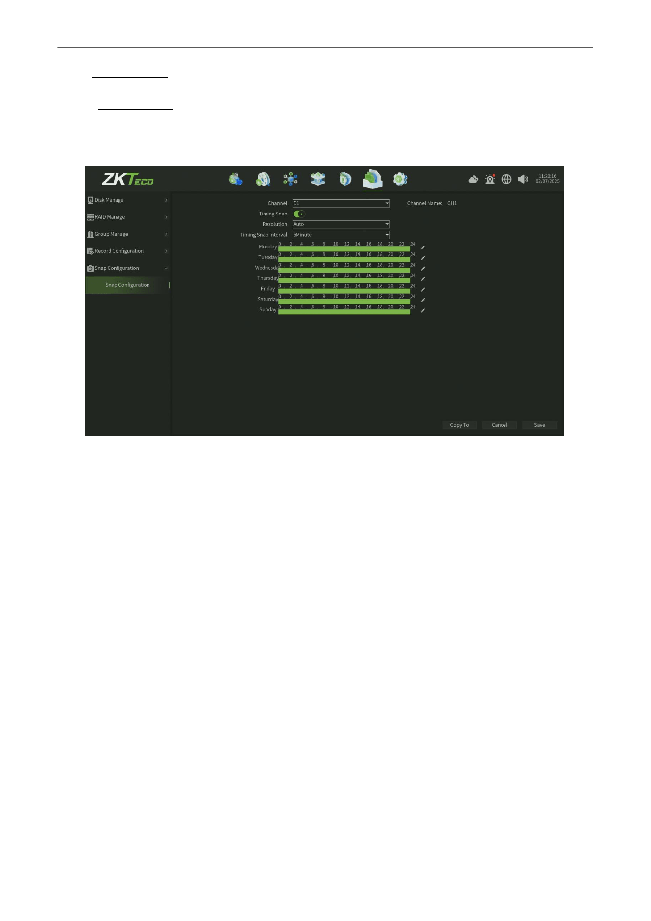
Network Video Recorder
User
Manual
P a g e
|
66
Copyright©2025 ZKTECO CO., LTD. All rights reserved.
9.5.
Snap Config
9.5.1.
Snap Config
The Snap Config interface,you can set the Timing Snap plan and Snap image format configuration, as shown in figure
9.5.1.1.
Figure 9.5.1.1 Snap Config
Parameter:
1. Channel :
Select the channel.
2.
Timing Snap : Check to enable the Channel Timing Snap.
3.
Resolution:
Set the snap image reolution,default value is auto.
4.
Timing Snap Interval : Set the Timing Snap interval time,default value is 5 minutes.
5.
Schedule : You can set the record schedule time on the schedule form.
6.
Copy to:
Click the copy to button and select the specific or all channels to copy the record configuration.
7.
Click Save button to save the settings.
Network Video Recorder
User
Manual
P a g e
|
67
Copyright©2025 ZKTECO CO., LTD. All rights reserved.
10.
System
Manage
Click icon,enter into the system manage interface,this part includes four parts altogether, note the following
instructions,as shown in figure 10.1.
Figure 10.1 System Manage Interface
10.1.
System
Configuration
This modelincludes five parts altogether ( System Setting,TimeSetting,Preview Setting,System Setting, System
Information,Security Setting ),as shown in figure 10.1.
Figure 10.1 System Configuration Interface
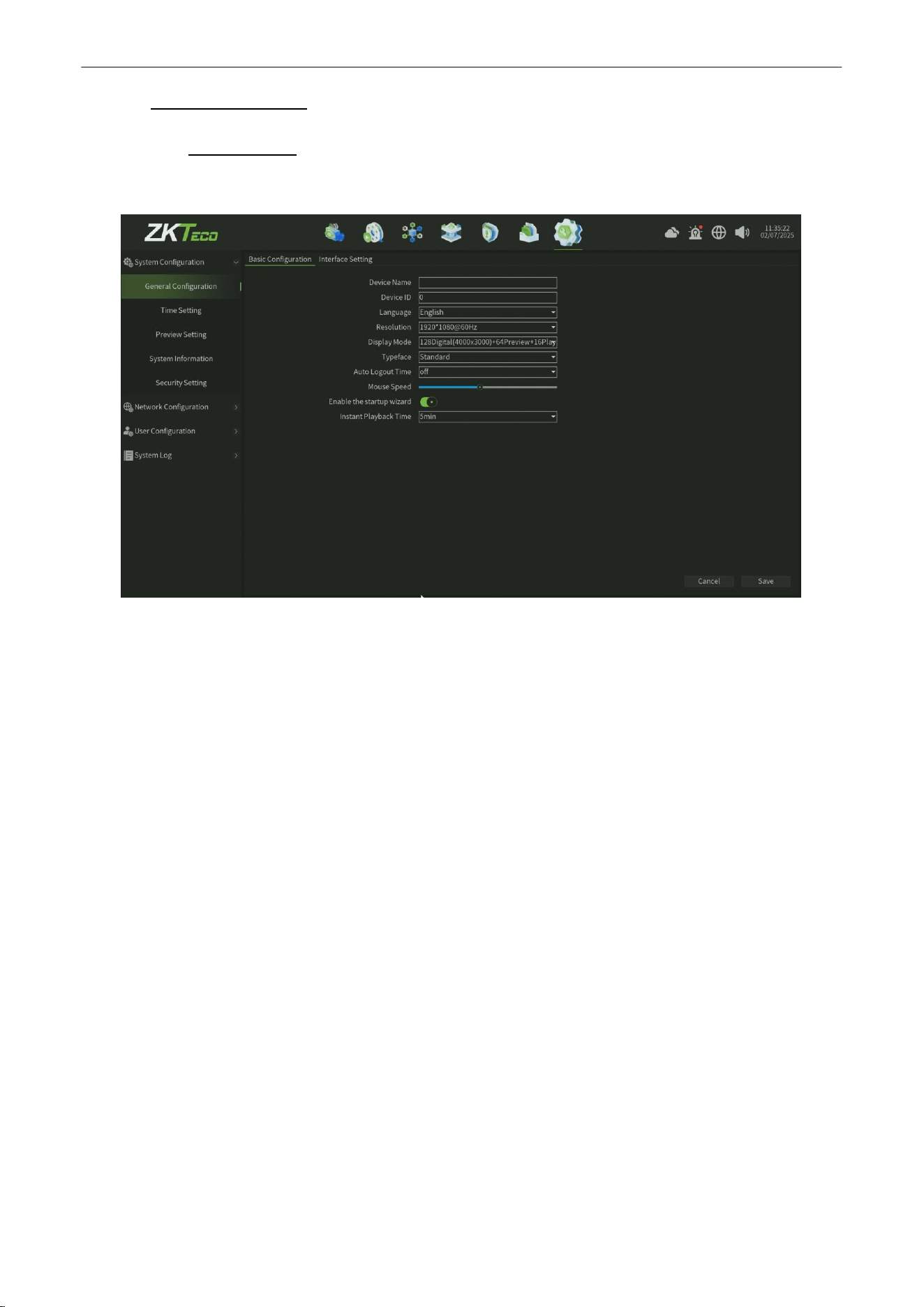
Network Video Recorder
User
Manual
P a g e
|
68
Copyright©2025 ZKTECO CO., LTD. All rights reserved.
10.1.1.
System Setting
10.1.1.1.
Basic Config
The System Basic Parameter Setting interface, as shown in figure 10.1.1.1.
Figure 10.1.1.1 Basic Setting Interface
Parameter:
1.
Device Name :
Edit device name.
2.
Device ID : Display the device id.
3.
Language :
Set the Language.
4.
Resolution : Set NVR support resolution and frequency.
5.
Show Mode:There are different display modes,the preview interface device list refresh in time after modify
successfully.
6.
Typeface : Set the Typeface for NVR.
7.
Auto Logout Time :
Set the Auto Logout Time for NVR.
8.
Mouse Speed : Adjust the speed of the mouse, it come into effect immediately.
9.
Start the startup wizard : Enable the StartUp wized fuction.
10.
Real Playback Time : Set the Real Playback Time for NVR.
11. Save
: Click Save button to save the setting.
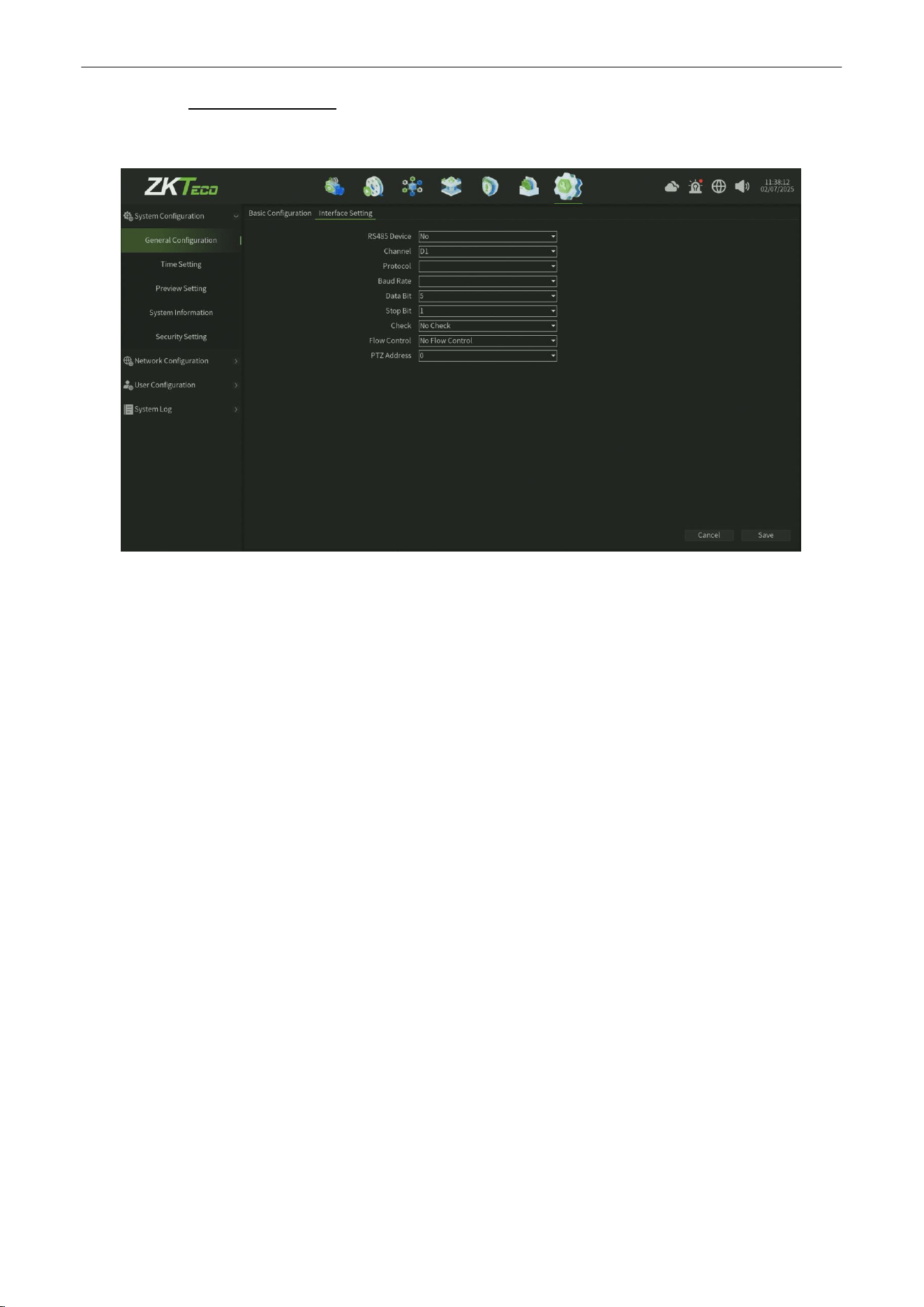
Network Video Recorder
User
Manual
P a g e
|
69
Copyright©2025 ZKTECO CO., LTD. All rights reserved.
10.1.1.2.
Interface Setting
The System Interface Setting interface, as shown in figure 10.1.1.2.
Figure 10.1.1.2 Basic Setting Interface
Parameter:
1.
RS485 Device :
There are three RS485 device typeoptions ( No, PTZ Control, RS485 Keyboard ), you can select the one of
options and devicewill reboot ,after rebbotyou can configthe corresponding setting infomation.
2.
Channel :
Select the Channel for configuration.
3.
Protocol : There are two PTZ protocol options ( pelco P and pelco D), you can selectthe one of options and modify the
settings.
4.
BAUD Rate: Set the Baud Rate for correspongding ptz protocol.
5.
Data Bit :
Set the Data Bit for correspongding ptz protocol.
6.
Stop Bit : Set the Stop Bit for correspongding ptz protocol.
7.
Check :
There are three Parity mode ( No Check , Odd Check and Even-Parity Check ), you can select the one of optionsfor
corresponding ptz protocol.
8.
Flow Control :
There are threeFlow Control mode ( No Flow Control, Soft Flow Control andHard Flow Control ), you can
selectthe one of options for corresponding ptz protocol..
9.
PTZ Address :
Select the PTZ Address ( up to 255 value)..
10. Save
: Click Save button to save the setting.
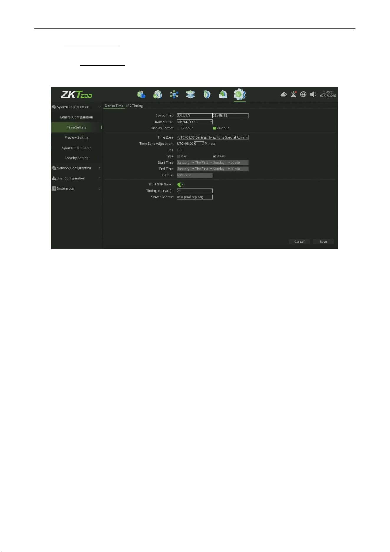
Network Video Recorder
User
Manual
P a g e
|
70
Copyright©2025 ZKTECO CO., LTD. All rights reserved.
10.1.2.
Time Setting
10.1.2.1.
Device Time
The Device Time Setting Interface , as shown in figure 10.1.2.1.
Figure 10.1.2.1 Device Time Setting Interface
Parameter:
1.
Device time:
Can manually modify the device time, set the time, click
Modify
, then save time.
2.
Data Format: Set the data format.
3.
Time zone:
Switch time zones, the page will pop up a new date and time, there is daylight saving time function
part time zone, the time zone is with functions of fine-tuning.
4.
SummerTime:
Enable Summer Time, just need to finish setting the start and end time.
5.
Start NTP Server : Enable/Disable NTP (the device needs to access network).
6.
Save
: Click Save button to save the setting.
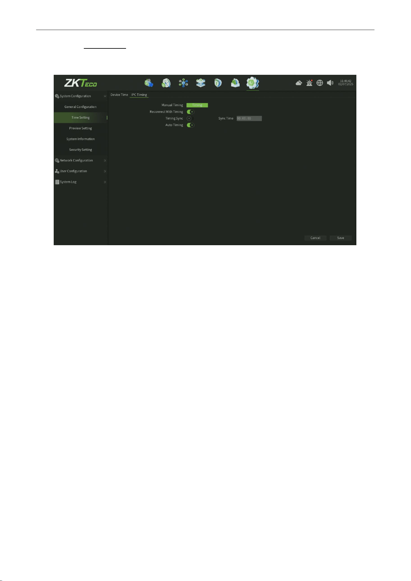
Network Video Recorder
User
Manual
P a g e
|
71
Copyright©2025 ZKTECO CO., LTD. All rights reserved.
10.1.2.2.
IPC Timing
The IPC Timing Setting Interface , as shown in figure 10.1.2.2.
Figure 10.1.2.2 IPC Timing Setting Interface
Parameter:
1.
Manual Timing: Click Manual Timing button, adjust the IPC time as same as device time.
2.
Auto Timing:
Enable the auto timing, the IPC will be timing when it is different to the device time.
3.
Reconnect with Time : Enable the reconnect timing, the IPC will be timing after reconnect to device.
4.
TimingSync:EnabletheTimingsync,theIPCwillbetimingonthetimeyousetting.
5. Save
: Click Save button to save the setting.
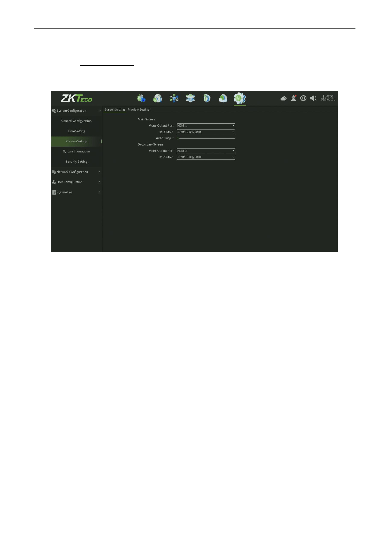
Network Video Recorder
User
Manual
P a g e
|
72
Copyright©2025 ZKTECO CO., LTD. All rights reserved.
10.1.3.
Preview Setting
10.1.3.1.
Screen Setting
The Screen Setting Interface , as shown in figure 10.1.3.1.
Figure 10.1.3.1 Screen Setting Interface
Parameter:
Main Screen : The Main Screen setting information
1.
Video Output Port : Select the HDMI 1 or VGA 1 output port ,then you can configure the screen parameters.
2.
Resolution :
Select the Resolution for the Main Screen display.
3.
AudioOutput :
Adjust the Audio Output value for Main Screen.
Secondary Screen : The Secondary Screen setting information
(It can be configured only under the
premise of connecting the secondary screen)
1.
Video Output Port : Select the HDMI 1 or VGA 1 output port ,then you can configure the screen parameters.
2.
Resolution :
Select the Resolution for the Secondary Screen display.
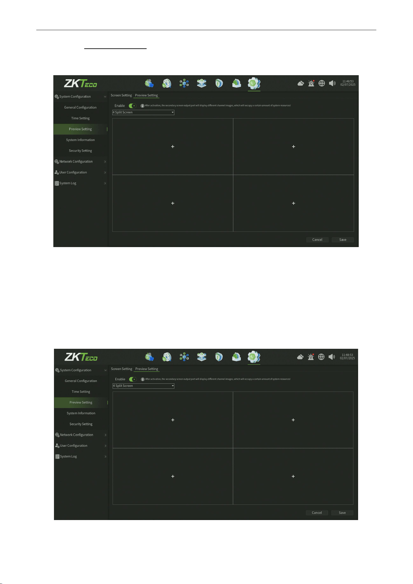
Network Video Recorder
User
Manual
P a g e
|
73
Copyright©2025 ZKTECO CO., LTD. All rights reserved.
10.1.3.2.
Preview Setting
The Preview Setting Interface , as shown in figure 10.1.3.2.1.
Figure 10.1.3.2.1 Preview Setting Interface
Warn:
The parameters you have set will only take effect after restarting.
1.
Enable : enable the Preview setting,After activation,the secondary screen output port will display different channel
images,which will occupy a certain amount of system resources!
Setting
After reataring , you can set the preview screen mode as shown in figure 10.1.3.2.2.
Figure 10.1.3.2.2 Preview Setting
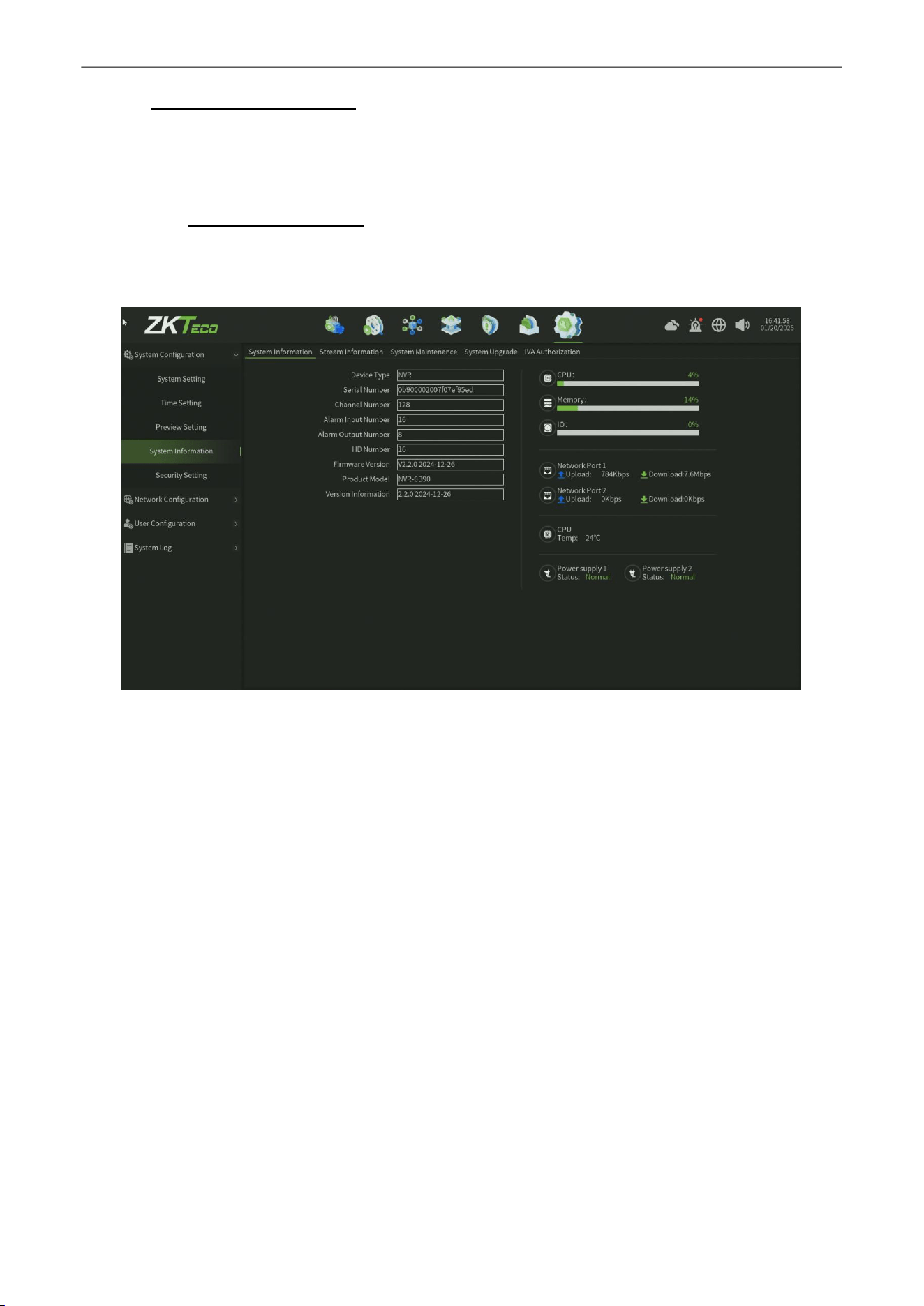
Network Video Recorder
User
Manual
P a g e
|
74
Copyright©2025 ZKTECO CO., LTD. All rights reserved.
10.1.4.
System Information
Can view the device System information,
S
tream information,System Maintenance,System upgrade and
IVA
Authorization.
10.1.4.1.
System Information
Device System information interface, as shown in figure 10.1.4.1, You can view the basic system information of device
and a visual data window on the right side of the page.
Figure 10.1.4.1 SystemInformation
Parameter:
1.
Device Type :
The defalut device type value is NVR.
2.
Serial Number : Display the device Serial Number,this number is unique for device ,is important for check
somthing like authorization.
3.
Channel Number : Display the Max channel number of device addding.
4.
Alarm input Number : Display the alarm input number of device.
5.
Alarm output Number :
Display the alarm output number of device.
6.
HD Number :
Display the Max HDD number of device compatibility.
7.
Firmware Version : Display the firmware version of device.
8.
Product Model :
Display the device model.
9.
Version Information : Display the version information of device.
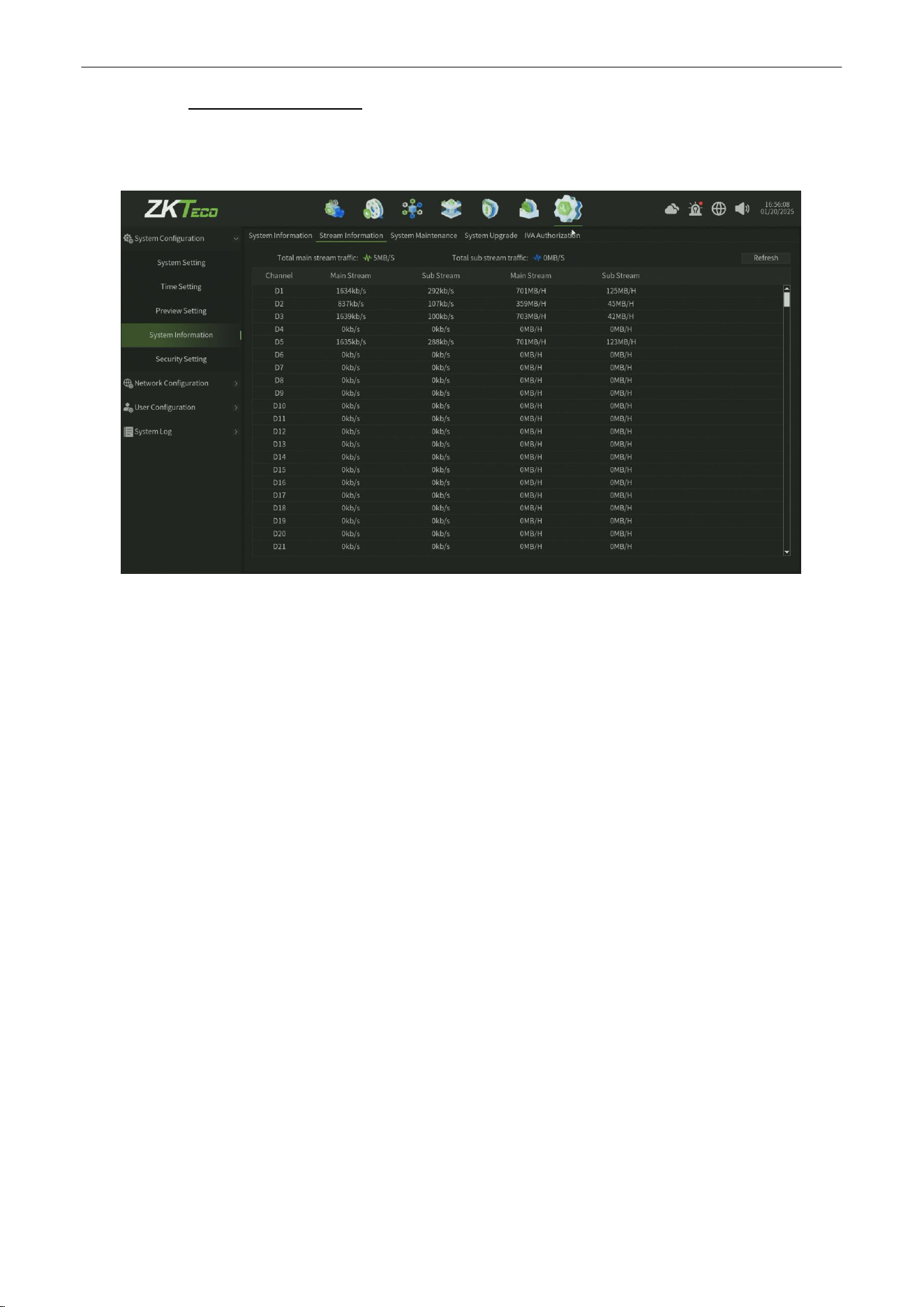
Network Video Recorder
User
Manual
P a g e
|
75
Copyright©2025 ZKTECO CO., LTD. All rights reserved.
10.1.4.2.
Stream Information
Device Stream information interface, as shown in figure 10.1.4.2, You can view theTotal main stream traffic and total
substream traffic information of device.
Figure 10.1.4.2 StreamInformation
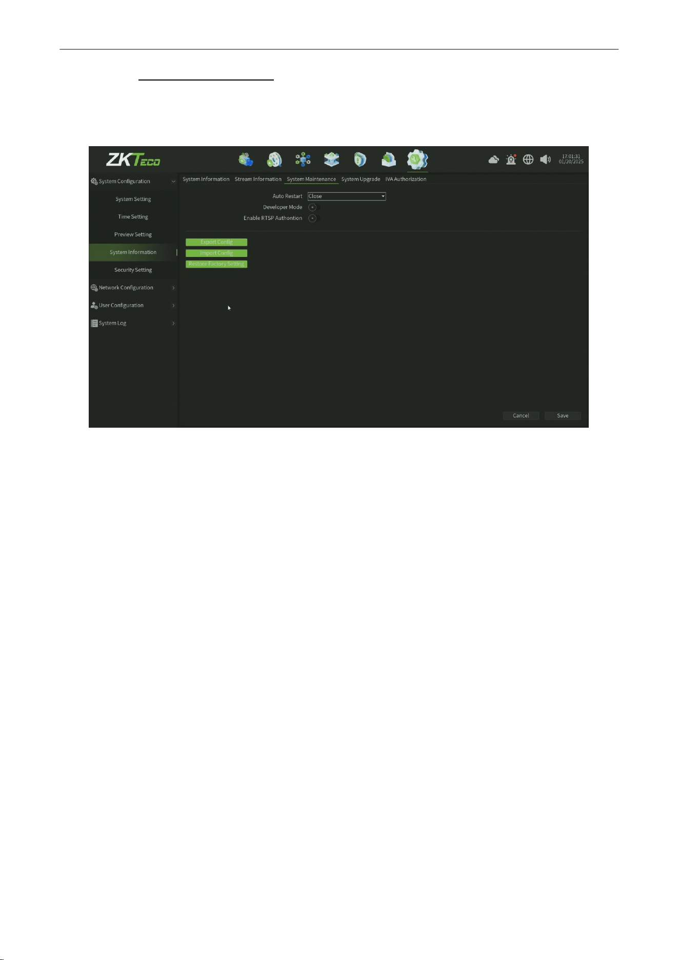
Network Video Recorder
User
Manual
P a g e
|
76
Copyright©2025 ZKTECO CO., LTD. All rights reserved.
10.1.4.3.
System Maintenance
Canset the maintenance mode ,developer mode and RTSP Authontion, as shownin figure10.1.4.3. You can
select the maintenance modein this interface.(ThedefaultmodeisClose).
Figure 10.1.4.3 System Maintenance
Parameter:
1.
Auto Restart :
When enable the maintenance function,you can select ONCE ,Every Day ,Weekly and set
corresponding time for auto Restarting.
2.
Develpoer Mode: When enable the developer option,that can enter into device back-end server by Telnet service.
3.
Enable RTSP Authontion :
When enable the RTSP Authontion option,the third-party platform or tool pull the
video stream by RTSP stream address need account authontion.
4.
Export Config :
You can export the device configuration information,the file can be annother device migration
configuration information by export config file.
5.
Import Config : You can migration configuration information by import config file from the annother device.
6.
Restore Factory Setting : You can restore the device for some parts or all configuration.
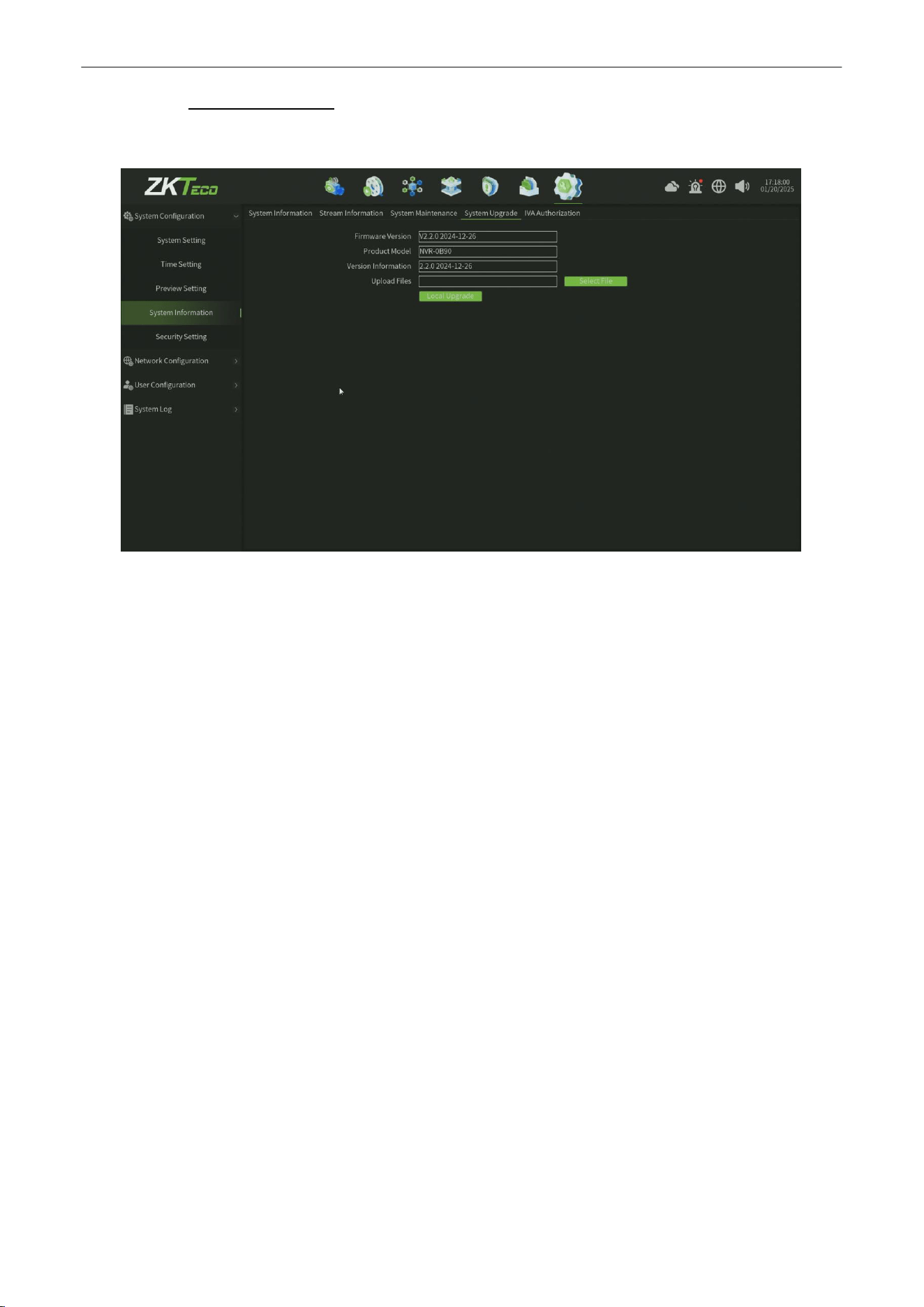
Network Video Recorder
User
Manual
P a g e
|
77
Copyright©2025 ZKTECO CO., LTD. All rights reserved.
10.1.4.4.
System Upgrade
The System upgrade interface, as showninfigure10.1.4.4.
Figure 10.1.4.4 System Upgrade
Steps:
1.
Loacl Upgrade : Click Select File, and then click local upgrade, the system will automatically restart
after
upgrading.
2.
After upgrading :
you will view the new version information of Firmware version,product Model and
Version information.
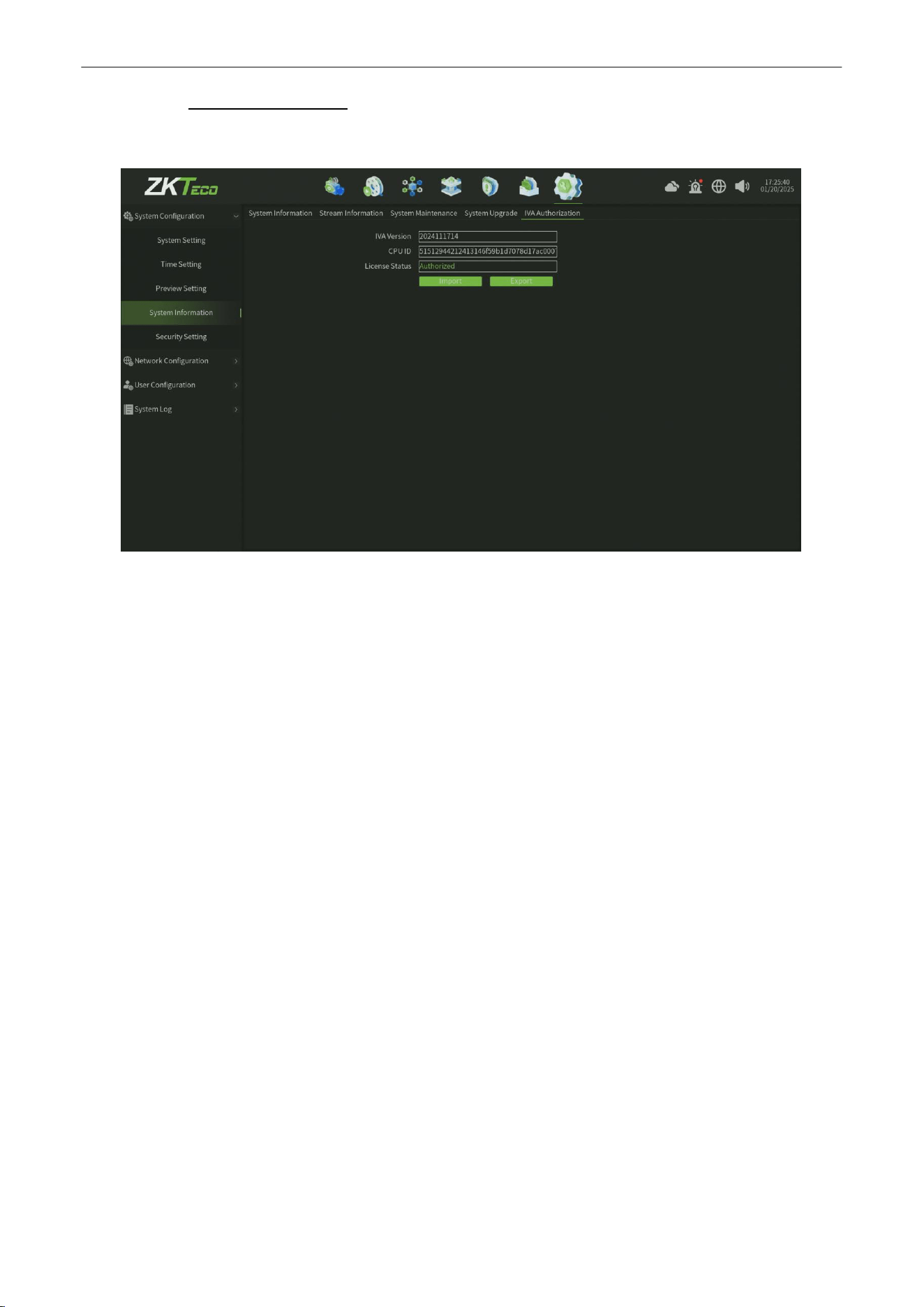
Network Video Recorder
User
Manual
P a g e
|
78
Copyright©2025 ZKTECO CO., LTD. All rights reserved.
10.1.4.5.
IVA Authorization
The IVA Authorization interface, as shown in figure 10.1.4.5.
Figure 10.1.4.5 IVA Authorization
Steps:
1.
Click Import, and then select the authorization file, the system will automatically restart
after importing.
2.
Also after authorization,you can export the authorization file.
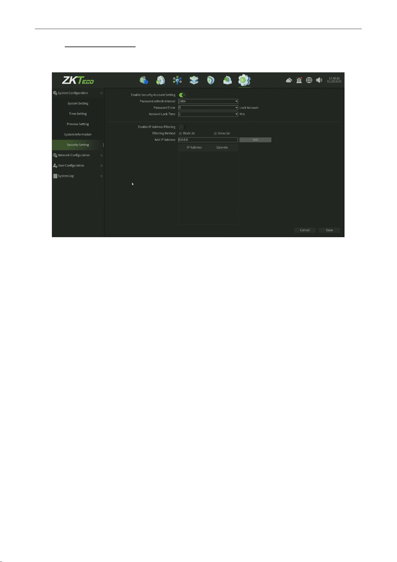
Network Video Recorder
User
Manual
P a g e
|
79
Copyright©2025 ZKTECO CO., LTD. All rights reserved.
10.1.5.
Security Setting
You can configure the Security Setting information,as shown in figure 10.1.5
.
Figure 10.1.5 Security Setting
Parameter:
1.
Enable Security Account Setting : After enable the account setting, you can configure the account setting.
•
Password refresh interval:
You can set this value between 1 to 5 mins.
• Password Error: You can set the errpr time between 5 to10 times before Locking Account.
• Account Lock Time: You can set the lock time in 1,5,10,15,30,60 mins.
2.
Enable IP Address Filter : You can add the ip address in block list and allow list.
•
Filtering Method :
There are two options ( Block List and Allow List) you can select.
•
Add IP Address : You can add the ip address for different filtering list.
3.
Save
:
Click Save button to save the setting.
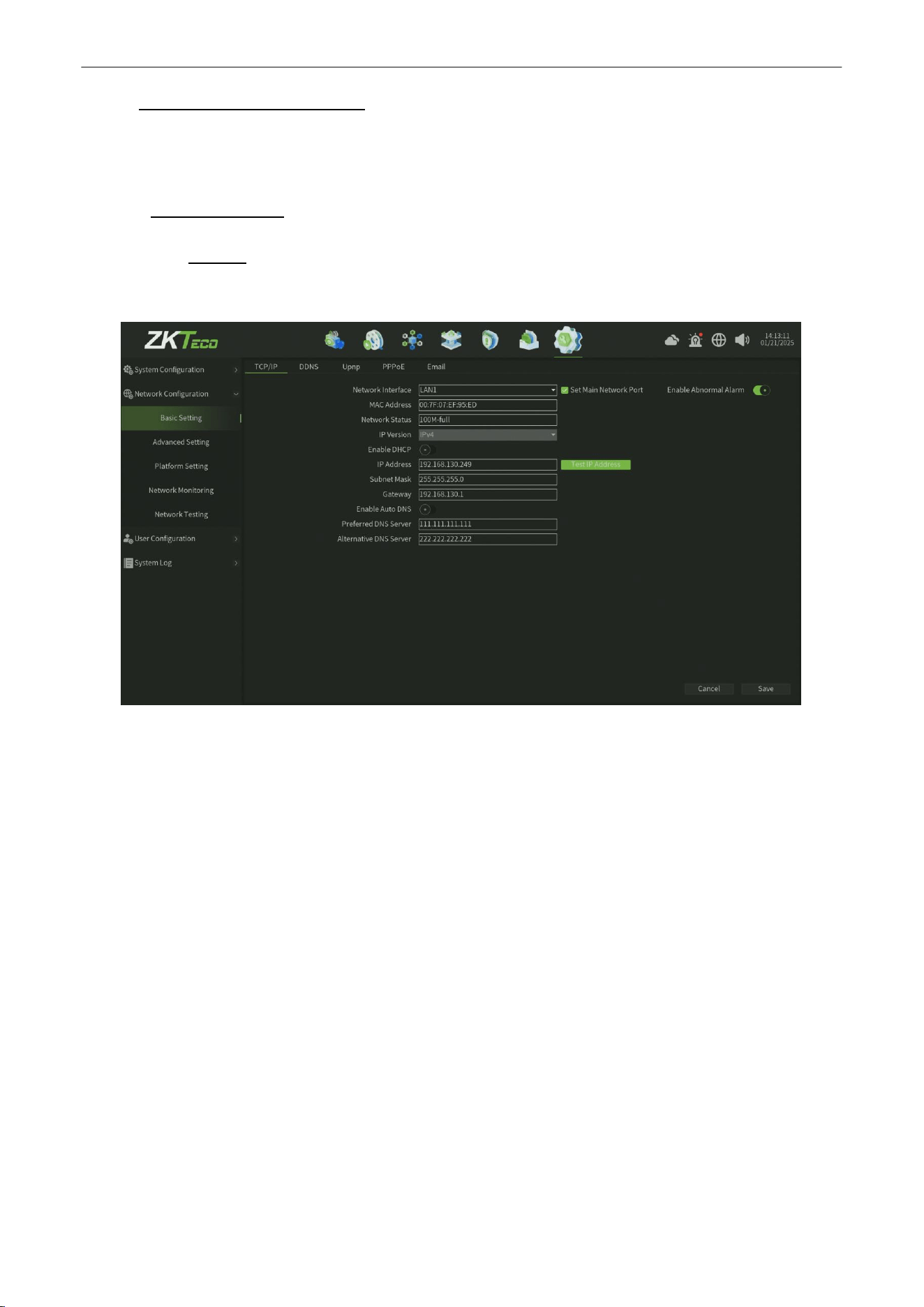
Network Video Recorder
User
Manual
P a g e
|
80
Copyright©2025 ZKTECO CO., LTD. All rights reserved.
10.2.
Network
Configuration
This model includes five parts altogether ( Basic Setting,Advanced Setting,Platform Setting,Network Monitoring,
Network Testing ).
10.2.1.
Basic Setting
10.2.1.1.
TCP/IP
The Network TCP/IP Parameter Setting interface, as shown in figure 10.2.1.1.
Figure 10.2.1.1 TCP/IP Service
Parameter:
1.
Network Interface :
According to the need can choose a different network card type.
2.
MAC Address : Show the physical address of the current network interface, unchangeable.
3.
Network Status :
Show the corresponding to network card bandwidth.
4.
IP Version : Show the IP protocol version,default value is IPV4.
5.
Enable DHCP :
When open it, IP/mask/the gateway cannot be set, if the current DHCP is effective, then it will obtain
new IP/mask/gateway the router assigned (remote login need to use the new IP address), if it doesn't take effect,
IP/mask/gateway will still show the previous address (can use the old IP address to remotely login equipment).
6.
IP Address : Set the IP address, the default IP of the network card 1 is 192.168.1.188, the default IP of the network
card 2 is 192.168.2.188.
7.
Subnet Mask:
Set the subnet mask.
8.
Gateway: Set the gateway address.
9.
Enable Auto DNS :
One click enable the auto dns service.
10.
Preferred DNS Server : Set the Preferred DNS Server ip address.
11.
Alternative DNS Server : Set the Alternative DNS Server ip address.
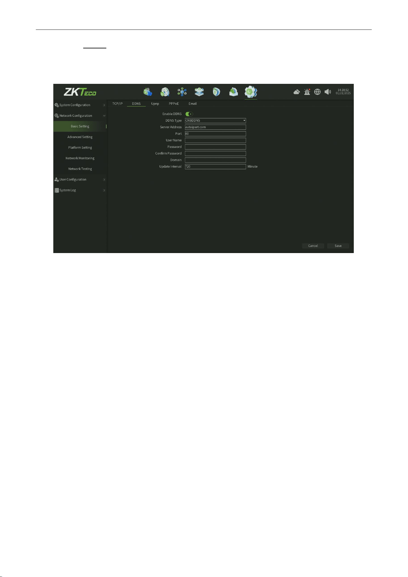
Network Video Recorder
User
Manual
P a g e
|
81
Copyright©2025 ZKTECO CO., LTD. All rights reserved.
10.2.1.2.
DDNS
The default is disable status, each set column cannot be set, it needs to switch to the "Enable DDNS" status, as shown in
figure 10.2.1.2, note that, this function need to ensure that device can normal access network when using.
Figure 10.2.1.2 DDNS Service
Parameter:
1.
Enable DDNS :
One click to enable DDNS service.
2.
DDNS Type : There are 11 types of the defaulted list.
3.
Server Address : Each server type is corresponding to the existing default server domain name;
4.
Port :
Each server type is corresponding to the existing default port.
5.
User Name : Manually enter the correct user name.
6.
Password :
Manually enter the correct password.
7.
Confirm Password : Enter the correct password again.
8.
Domain :
Manually enter the correct domain name (After the function is OK, you can use the domain name remote
access device).
9.
Update Interval : Set the update interval time.
10. Save
:
Click Save button to save the setting.
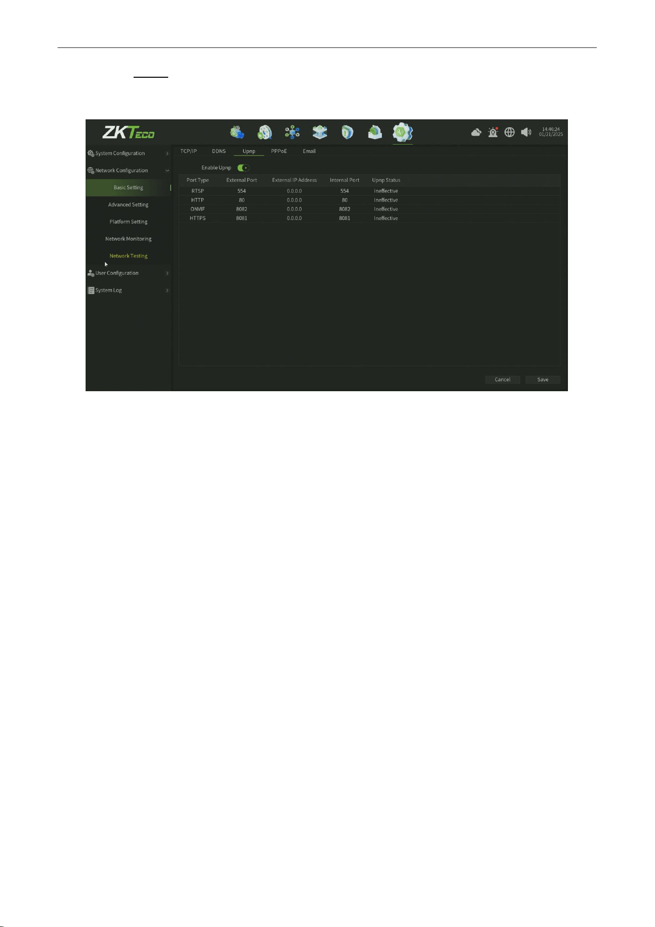
Network Video Recorder
User
Manual
P a g e
|
82
Copyright©2025 ZKTECO CO., LTD. All rights reserved.
10.2.1.3.
Upnp
The Network Upnp Service Setting interface, as shown in figure 10.2.1.3.
Figure 10.2.1.3 Upnp Service
Parameter:
1.
Port Type :
Display the different protocol service type.
2.
Exteral Port : You can set the corresponding export port.
3.
Exteral Address : Display the exteral address.
4.
Interal Port :
Display the Interal Port.
5.
Upnp Status :
Display the Upnp servicestatus.
6. Save
:
Click Save button to save the setting.
Note :
Defaulted RTSP , HTTP, HTTPS and ONVIF port numbers are respectively 554, 80, 8081 and 8082, port numbers can be
modified (modifying the internal port need to restart the device to take effect ), UPnP status is defaulted to ineffective
state, it will obtain the external IP address after take effect.
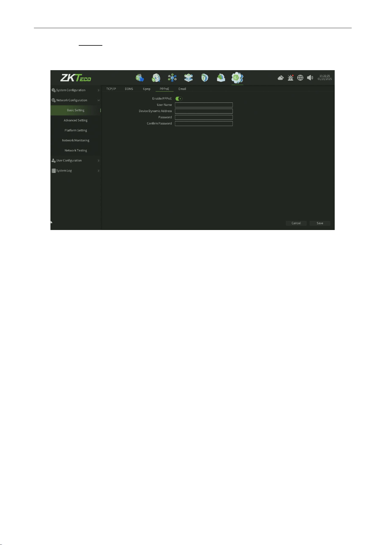
Network Video Recorder
User
Manual
P a g e
|
83
Copyright©2025 ZKTECO CO., LTD. All rights reserved.
10.2.1.4.
PPPoE
The Network PPPoE Service Setting interface, as shown in figure 10.2.1.4.
Figure 10.2.1.4 Email Service
Parameter:
1.
Enable PPPoE :
One click to enabel the PPPoE service.
2.
User Name : Enter the PPPoE user name.
3.
Device Dynamic Address : set the Device Dynamic Address.
4.
Password :
Enter the PPPoE user name.
5.
Confirm Password :
Enter the correct password again.
6. Save
:
Click Save button to save the setting.
Note :
Need to fill in the correct PPPoE user name and password, if the network connect, can obtain the dynamic
address of
thedevice.
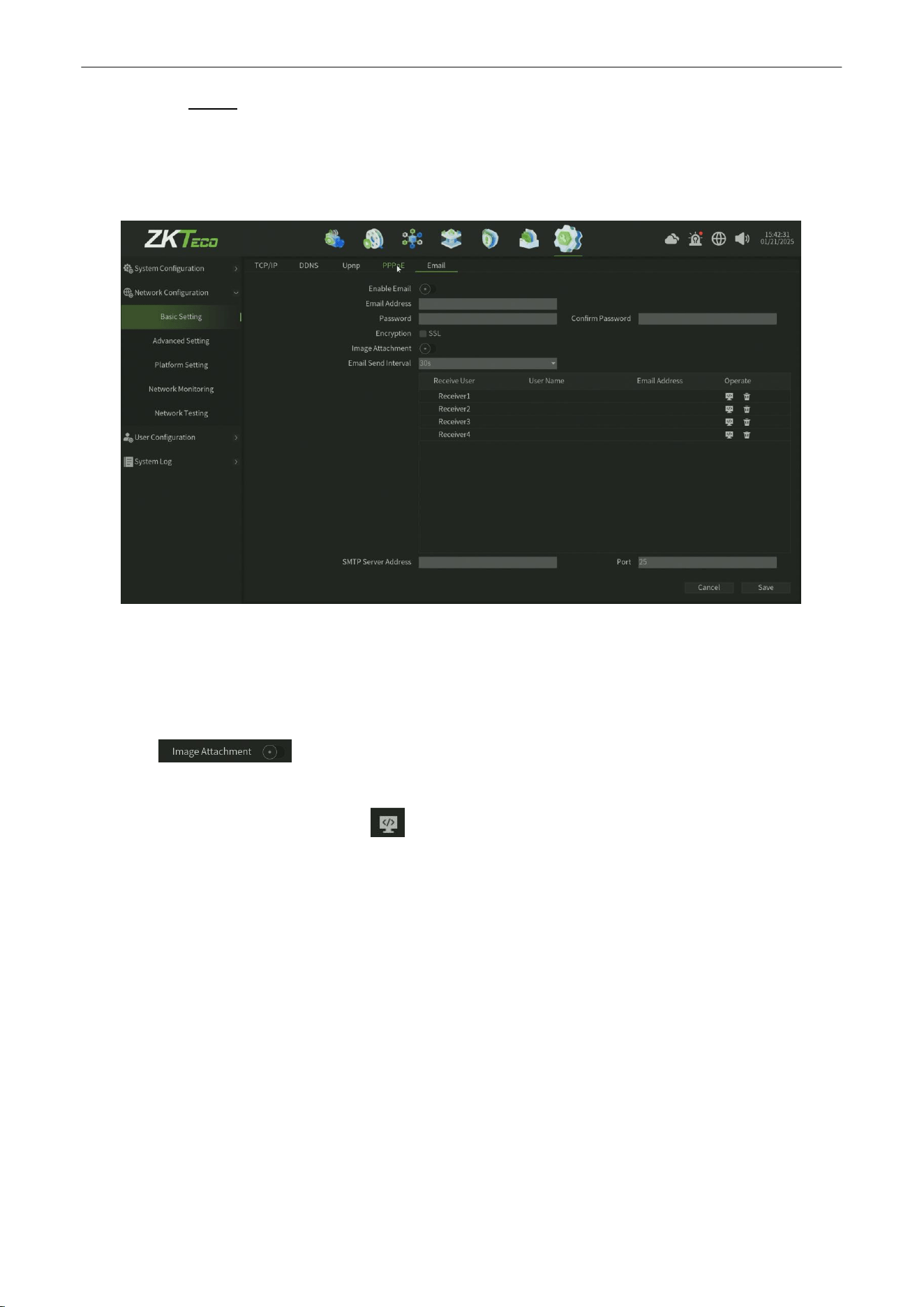
Network Video Recorder
User
Manual
P a g e
|
84
Copyright©2025 ZKTECO CO., LTD. All rights reserved.
10.2.1.5.
Email
The settings in this page is used with "Email Linkage" in the "Linkage Setting ", the sender email address and password,
the recipient email address, SMTP server address and port information need to input correctly in the corresponding field
according to the requirements of the format, here are other additional features on the page, as shown in figure 11.4.
Figure 10.2.1.5 Email Service
Steps :
1.
Fill in the multiple recipient mailbox, the sender email address will send E-mail to multiple recipients’ mailbox at
the same time.
2.
Check function, the mail the recipient received in his mailbox is with attachments, the
attachment content is linkage capture file of the corresponding channel (zip format).
3.
Click the "test mail" corresponding field icon, Let the sender mailbox to send mail to the recipient's
mailbox, the success or failure will pop-up tips.
Note :
Use Email linkage function need to ensure a good network environment, then the device can smoothly access external
network.
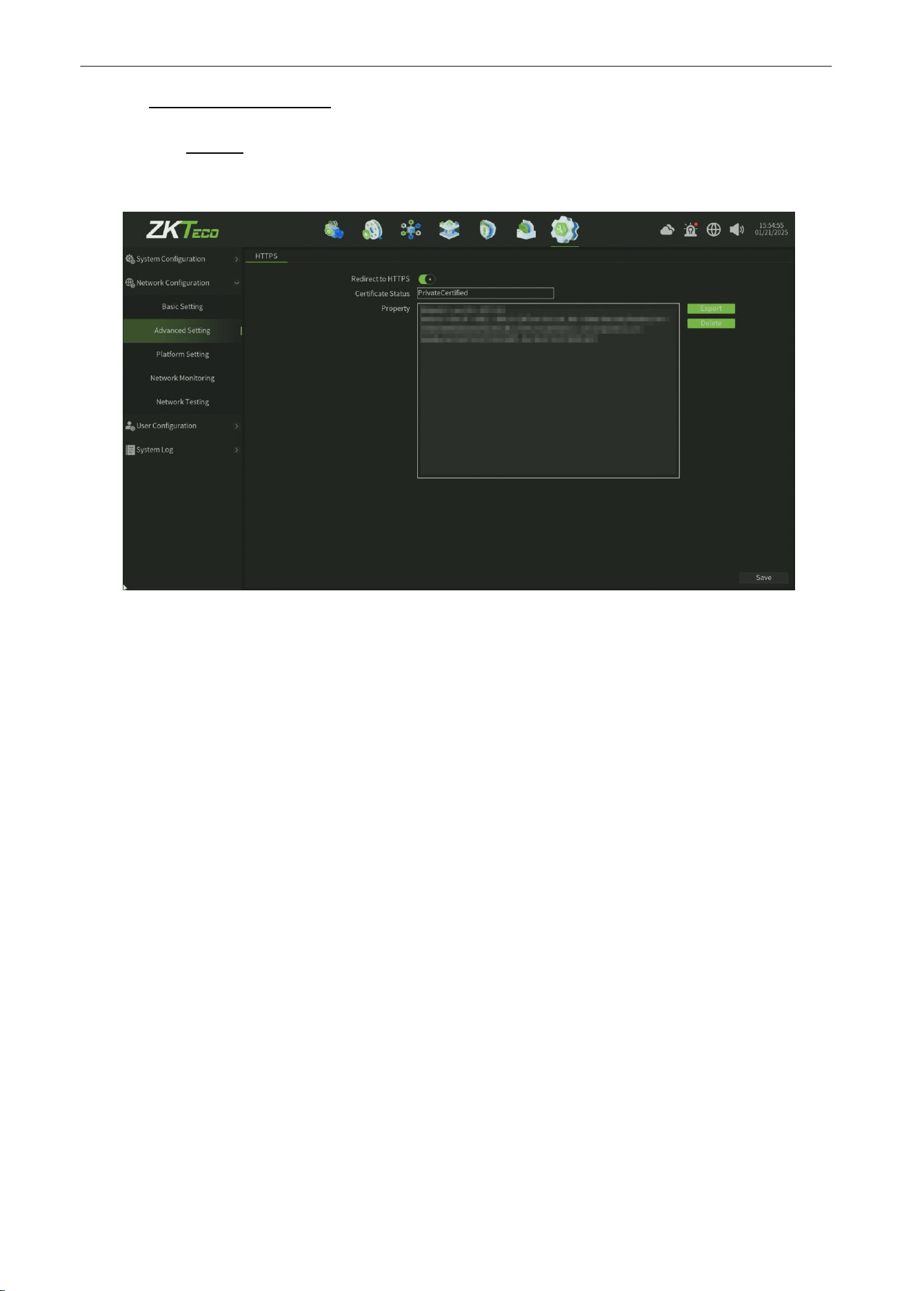
Network Video Recorder
User
Manual
P a g e
|
85
Copyright©2025 ZKTECO CO., LTD. All rights reserved.
10.2.2.
Advanced Setting
10.2.2.1.
HTTPS
The Network HTTPS Service Setting interface, as shown in figure 10.2.2.1.
Figure 10.2.2.1 HTTPS Service
Parameter:
1.
Redirect to HTTPS :
One click to enabel the HTTPS service and redirect the HTTP service to HTTPS.
2.
Certificate Status : Display the HTTPS certificate status.
3.
Property :
Display the HTTPS certificate property.
4.
Export : One click to export the certificate file.
5.
Delete : One click to delete the certificate Property.
6. Save
:
Click Save button to save the setting.
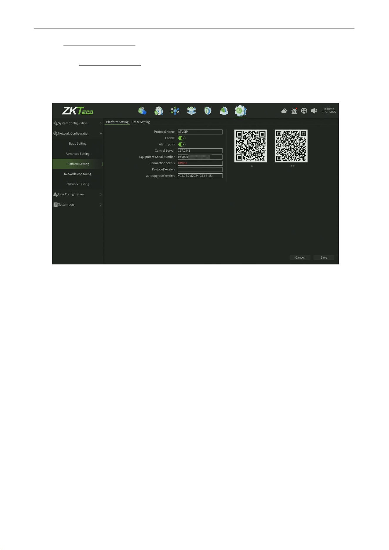
Network Video Recorder
User
Manual
P a g e
|
86
Copyright©2025 ZKTECO CO., LTD. All rights reserved.
10.2.3.
Platform Setting
10.2.3.1.
Platform Setting
The Platform Setting interface, as shown in figure 10.2.3.1,Defaulted to enable P2P and Web Server protocol (Support
the device remotely login).
Figure 10.2.3.1 Platform Setting
Parameter:
1.
Protocol Name :
Default value is ATVSIP.
2.
Enable : One click to Enable P2P service (Only enable the p2p interface on device,this service also need device
could access public network).
3.
Central Server :
Default Central Server is local host,value 127.0.0.1.
4.
Protocol Version : Display the Protocol version.
5.
Autoupgrade Version : Display the current P2P service version.
Steps :
1.
Using mobile phone scan the APP QR code to download and install the Mobile Application.
2.
Register and log in the application.
3.
Scan the ID QR code in the application.
4.
Enter the device user name and password.
5.
After connect success,then you can preview and manage the device in the application.
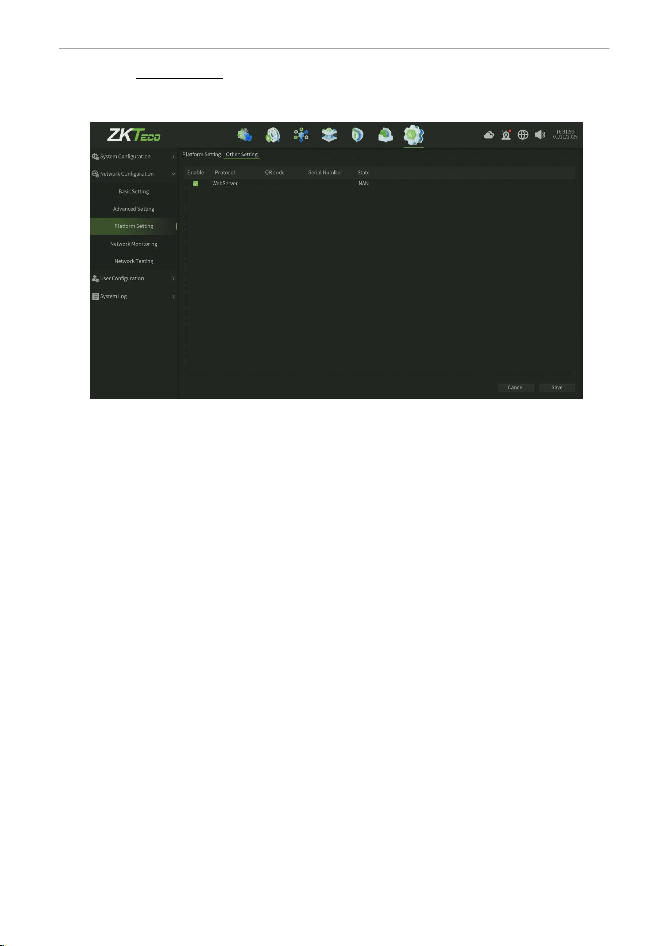
Network Video Recorder
User
Manual
P a g e
|
87
Copyright©2025 ZKTECO CO., LTD. All rights reserved.
10.2.3.2.
Other Setting
The Platform Other Setting interface, as shown in figure 10.2.3.2.
Figure 10.2.3.2 Platform Other Setting
Note:
Other services enable according to the need. Note that, enable/disable parts of service need to restart the device.
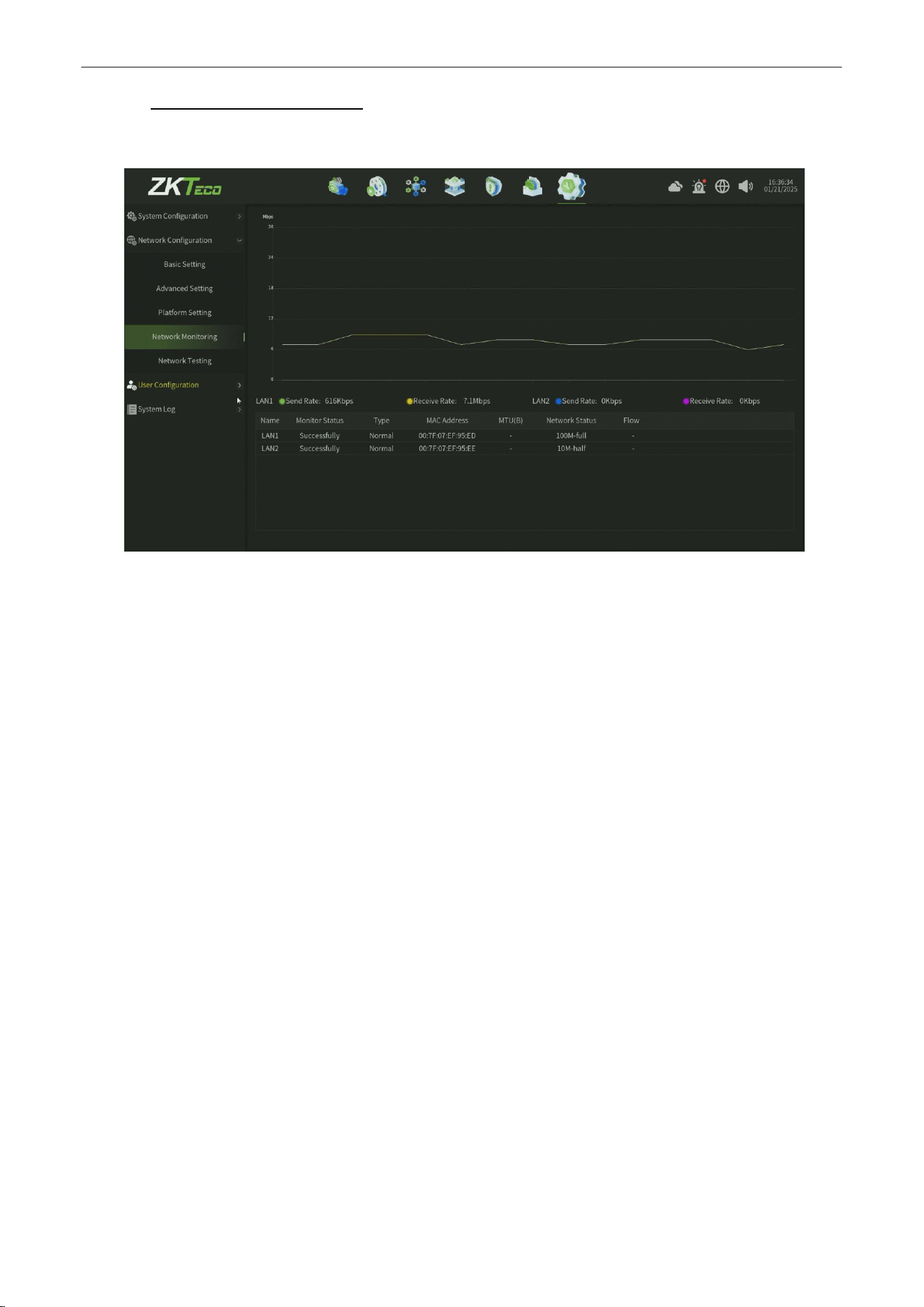
Network Video Recorder
User
Manual
P a g e
|
88
Copyright©2025 ZKTECO CO., LTD. All rights reserved.
10.2.4.
Network Monitoring
As shown in figure 10.2.4, can monitor the network traffic of the current device.
Figure 10.2.4 Network Monitoring
Note:
Real time monitor and display the network flow data for each network card.
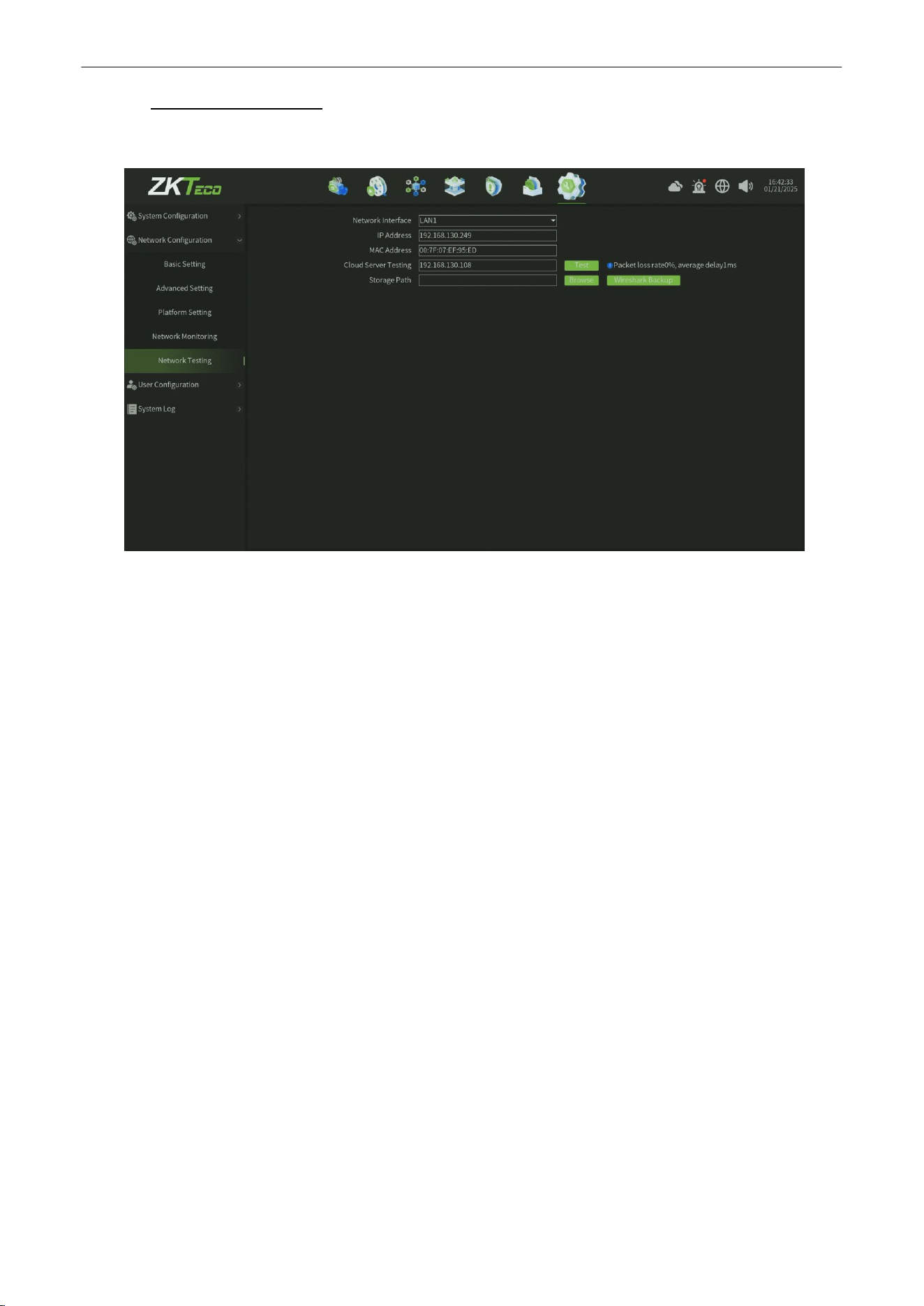
Network Video Recorder
User
Manual
P a g e
|
89
Copyright©2025 ZKTECO CO., LTD. All rights reserved.
10.2.5.
Network Testing
The Network Testing interface, as shown in figure 10.2.5.
Figure 10.2.5 Network Testing
Parameter:
1.
Network Interface:
Select the network card ( LAN1 or LAN2 ).
2.
IP Address : Display the device current ip address.
3.
MAC Address : Display the device mac address.
4.
Cloud Server Testing :
Enter into the target ip address or domain,then click test button,will get a response to
judge the network connectivity status.
5.
Storage Path : Click browse, set up storage paths, click Wireshark backup, then complete the
backup.
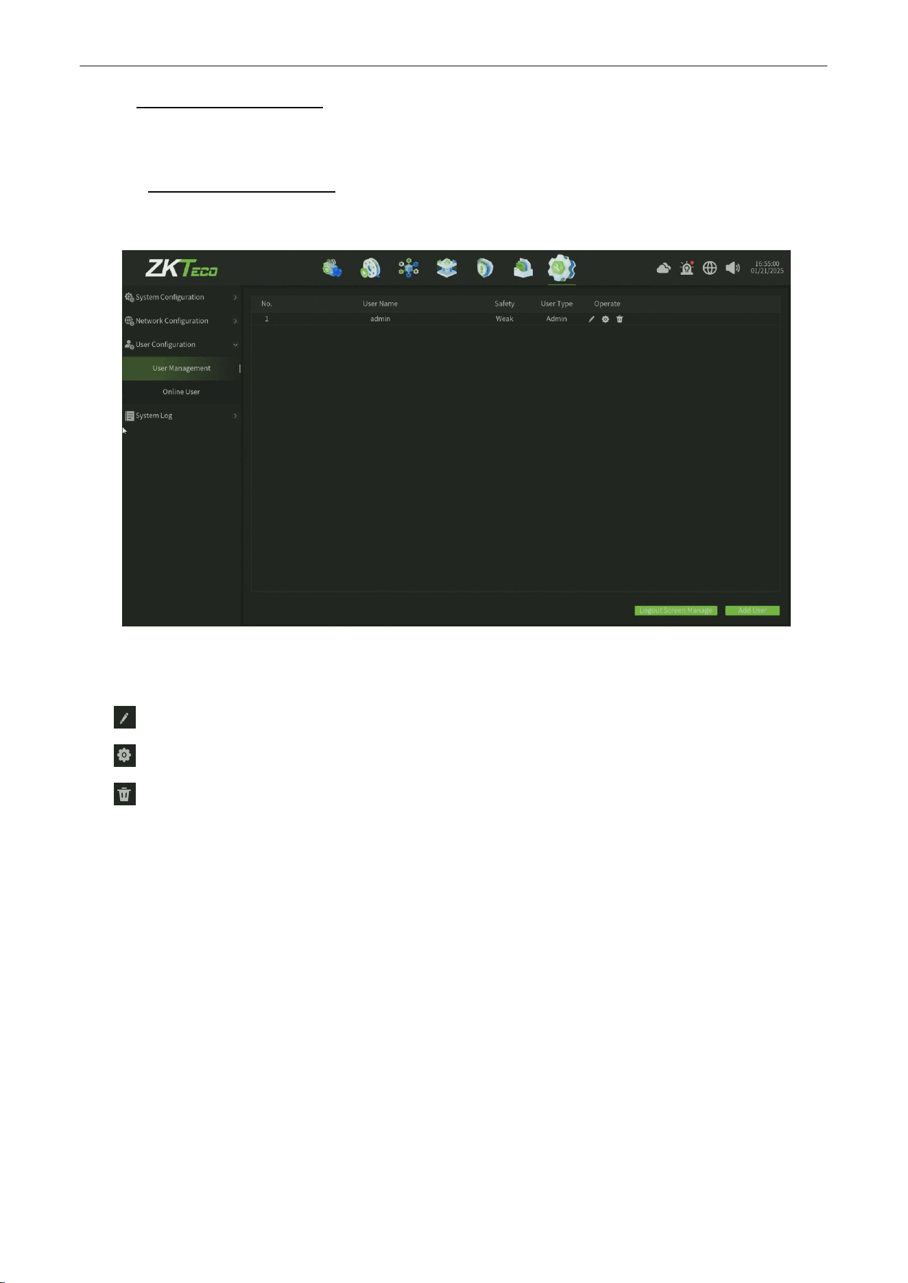
Network Video Recorder
User
Manual
P a g e
|
90
Copyright©2025 ZKTECO CO., LTD. All rights reserved.
10.3.
User
Configuration
This model includes two parts altogether ( User Management , Online User ).
10.3.1.
User Management
The User Management interface, as shown in figure 10.3.1.
Figure 10.3.1 User Management
Parameter:
1.
:
Edit button,click this button can edit the user rights.
2.
:
Config button,click this button can get and modify the user information,as shown in figure 10.3.1.1.
3.
:
Delete button,click this button can delete the user ( can not delete administrator ).
4.
Logout Screen Manage : Click this button,then select the channel which you want displat and preview when the
user logout,as shown in figure 10.3.1.2.
5.
Add user :
Click this button, then enter into the user information to add a new user,as shown in figure 10.3.1.3.
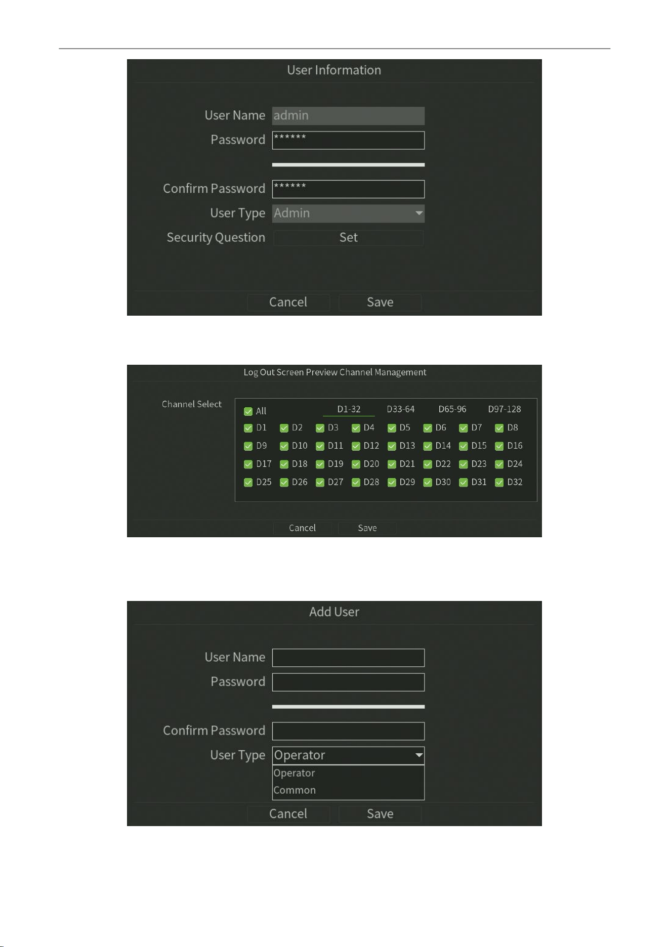
Network Video Recorder
User
Manual
P a g e
|
91
Copyright©2025 ZKTECO CO., LTD. All rights reserved.
Figure 10.3.1.1 User Configuration
Figure 10.3.1.2 Logout Screen Preview Channel Management
Figure 10.3.1.3 Add User

Network Video Recorder
User
Manual
P a g e
|
92
Copyright©2025 ZKTECO CO., LTD. All rights reserved.
10.3.2.
Online User
The Online User interface, as shown in figure 10.3.2.
Figure 10.3.2 Online User
Note:
Display the Online User information in this page,Click Refresh can refresh the online user list infomation.
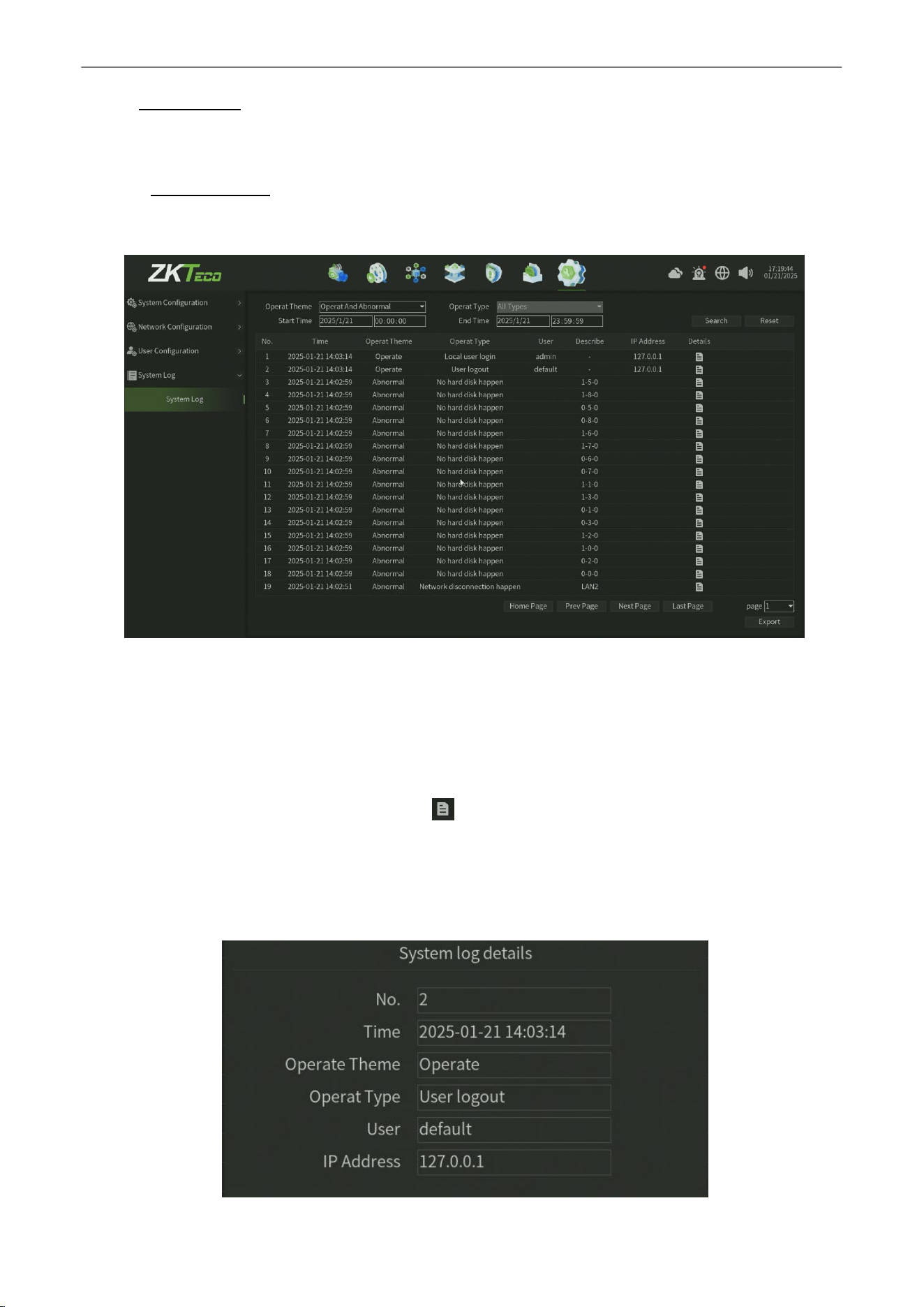
Network Video Recorder
User
Manual
P a g e
|
93
Copyright©2025 ZKTECO CO., LTD. All rights reserved.
10.4.
System Log
This model includes only one part ( System Log ).
10.4.1.
System Log
The System Log interface, as shown in figure 10.4.1.
Figure 10.4.1 System Log
Steps:
1.
Select the Operat Theme for System Log Search.
2.
Select the
Operat Type,
Such as
User Logout
,
Restart
.
3.
Set the Start Time andEnd Time.
4.
Click Search button to find logs and you can click
button to
view the detail on the pop window,as shown in
figure 10.4.1.1.
5.
Click Reset button can back to the default parameter of this interface.
6.
Click Export button can export the Alarm data(Note need plug the USB disk).
Figure 10.4.1.1 System Log Detail Information