boschdiagnostics.com
SMT500 Leak Detector
Operating Instructions

en
|
2
|
Operating Instructions |
SMT500 Leak Detector
SP01501467 | REV A | 4.2021
Bosch Automotive Service Solutions Inc
Safety Precautions
BEFORE OPERATING THIS TOOL, ALL OPERATORS SHOULD
READ AND UNDERSTAND THIS DOCUMENT AND FOLLOW
ALL SAFETY WARNINGS AND INSTRUCTIONS.
KEEP THESE INSTRUCTIONS WITH THE TOOL FOR FUTURE
REFERENCE. IF YOU HAVE ANY QUESTIONS, CONTACT YOUR
BOSCH REPRESENTATIVE OR DISTRIBUTOR.
DANGER
When an engine is operating, keep the service area well
ventilated or attach a building exhaust removal system to the
engine exhaust system. Engines produce carbon monoxide, an
odorless, poisonous gas that causes slower reaction time and
can lead to death or serious personal injury.
WARNING:
• All diagnostic work should be performed with the engine off
• Do not leave a vehicle unattended while equipment is
connected or operating
• Operates on a 12-volt battery: connect to battery (+) and
chassis ground (-)
• Vapor chamber can become hot. Do not lift or carry by
vapor chamber
• Do not perform tests near a source of spark of ignition
• When working with the fuel system, work in a well-venti-
lated area
• Always wear the appropriate safety protection
• Wear OSHA standard eyewear and protective gloves
when using this equipment
• When working with hydraulic or fuel lines, be careful
that liquids under pressure do not escape and create a
dangerous condition. Use adequate ventilation and make
sure there are no sparks or possibility of sparks that may
ignite any vapor.
• Wear an American National Standards Institute (ANSI) Z87.1
approved eye shield when testing or repairing vehicles.
• Objects propelled by whirling engine components or
pressurized liquids escaping may cause personal injury.
• Set the parking brake and block the wheels before test-
ing or repairing a vehicle. It is especially important to
block the wheels on front-wheel drive vehicles because
the parking brake does not hold the drive wheels.
• Do not drive the vehicle and operate the software at the
same time.
• Maintain adequate clearance around moving components
or belts during testing.
• Moving components and belts can catch loose clothing,
body parts, or test equipment and cause serious personal
injury or tool damage.
• Automotive batteries contain sulfuric acid and produce
explosive gases that can result in serious injury due to
ignition of gases. Keep lit cigarettes, sparks, ames, and
other ignition sources away from the battery at all times.
• Refer to the service manual for the vehicle being ser-
viced. Adhere to all diagnostic procedures and precau-
tions. Failure to do so could result in personal injury or
otherwise unneeded repairs.
• Use only specially designed replacement parts (brake
hoses and lines) for ABS equipped vehicles.
• After bleeding the brake system, check the brake pedal
for excessive travel or a ”spongy” feel. Bleed again if
either condition is present.
• When installing transmitting devices (Citizen Band radio,
telephone, etc) on ABS-equipped vehicles, do not locate
the antenna near the ABS control unit or any other con-
trol unit.
• This equipment has been tested and found to comply with
the limits for a Class B digital device, pursuant to Part 15
of the FCC Rules. These limits are designed to provide
reasonable protection against harmful interference in a
residential installation. This equipment generates and
radiates radio frequency energy and, if not installed and
used in accordance with the instructions, may cause harm-
ful interference to radio communications.
• Do not operate the tool with a damaged cord or connector.
Replace damaged cords and connectors immediately.
• Do not expose tool to rain, moisture, or snow.
• Verify that cords are located where they will not be
stepped on, tripped over, or otherwise become a safety
hazard or subjected to damage or stress.
• Do not store or leave your tool near a heat source such as
a radiator, replace, stove, electric heater, or other heat-
generating appliance or otherwise expose it to tempera-
tures in excess of 60ºC (140ºF). When heated to excessive
temperatures, battery cells could explode or vent, causing
personal injury or risk of re.
CAUTION:
• Do not place the tool on the distributor of a vehicle.
Strong electromagnetic interference can damage the tool.
• Never disconnect or reconnect any electrical connec-
tor while the ignition is on. Powertrain Control Module
(PCM) damage may result.
SP01501467 | REV A | 4.2021
Bosch Automotive Service Solutions Inc
SMT500 Leak Detector
|
Operating Instructions
|
3
|
en
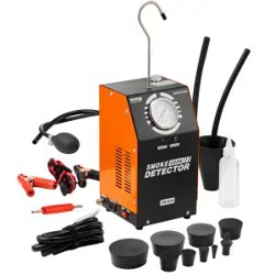
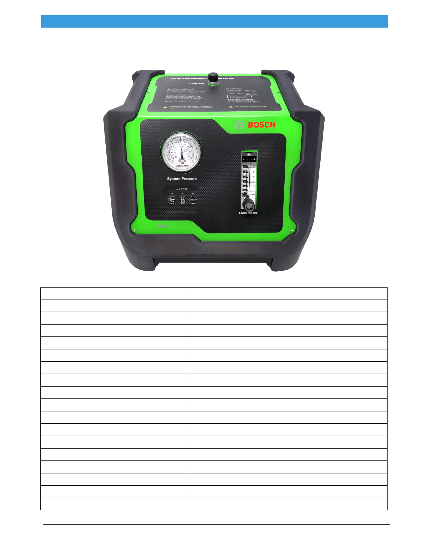
Specications
L x W x H 8 in. x 10 in.x 12.5 in. (20 cm x 25 cm x 33 cm)
Weight 10.3 lb (4.5 kg)
Shipping weight 18 lb (8 kg)
Power supply 12 volts DC; input power supply 11.5–14 VDC
Power consumption 8 amps
Output pressure 0.47 PSI / 13.0 in. H20 / 0.032 BAR
Operating temperature 30°F to 115°F (-1°C to 46°C)
Operating humidity No restrictions
Operating altitude No restrictions
Vapor output hose 10 ft (3 m)
Power supply cables 10 ft (3 m)
Operating modes Vapor test cycle/Air only test cycle
Pressure Supply Onboard micro air compressor
Micro-compressor duty cycle 100%
Housing material High-impact PC/ABS polycarbonate
Vapor chamber material Billet aluminum
Vapor chamber assembly Bolted
Vapor chamber warranty Lifetime
en
|
4
|
Operating Instructions |
SMT500 Leak Detector
SP01501467 | REV A | 4.2021
Bosch Automotive Service Solutions Inc
Reference Guide
1
2
3
7
6
5
4
1. Compound pressure gauge
• Indicates amount of pressure or vacuum
• Allows for decay/leak down test to confirm
repair is 100% complete
2. Flow meter
• Measures leak size as small as 0.010-in.
3. Flow control knob
• Open flow control valve to allow vapor/
pressure into the system
• Close flow control valve to lock out system
for pressure decay testing
4. Reset button
• Used for service functions only
5. Air-only test button
• Begins 5-minute air-only cycle to test
without vapor
• Blue light indicates onboard
microcompressor is generating air-only
6. Vapor test button
• Begins 5-minute vapor cycle
• Red light indicates vapor cycle
• Push again to stop testing
7. Power indicator light
• Green light indicates adequate power
8
9
10
11
8. Fluid fill port
• Turn counter clockwise to remove
dipstick
9. External gas input
• 1/4-in. NPT threaded port
• Connects external compressed gas
(inert gases such as nitrogen or CO2)
10. Battery power cables
• Connects to 12-Volt DC battery(+) and
chassis ground(-)
11. Vapor output hose
SP01501467 | REV A | 4.2021
Bosch Automotive Service Solutions Inc
SMT500 Leak Detector
|
Operating Instructions
|
5
|
en
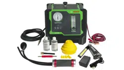
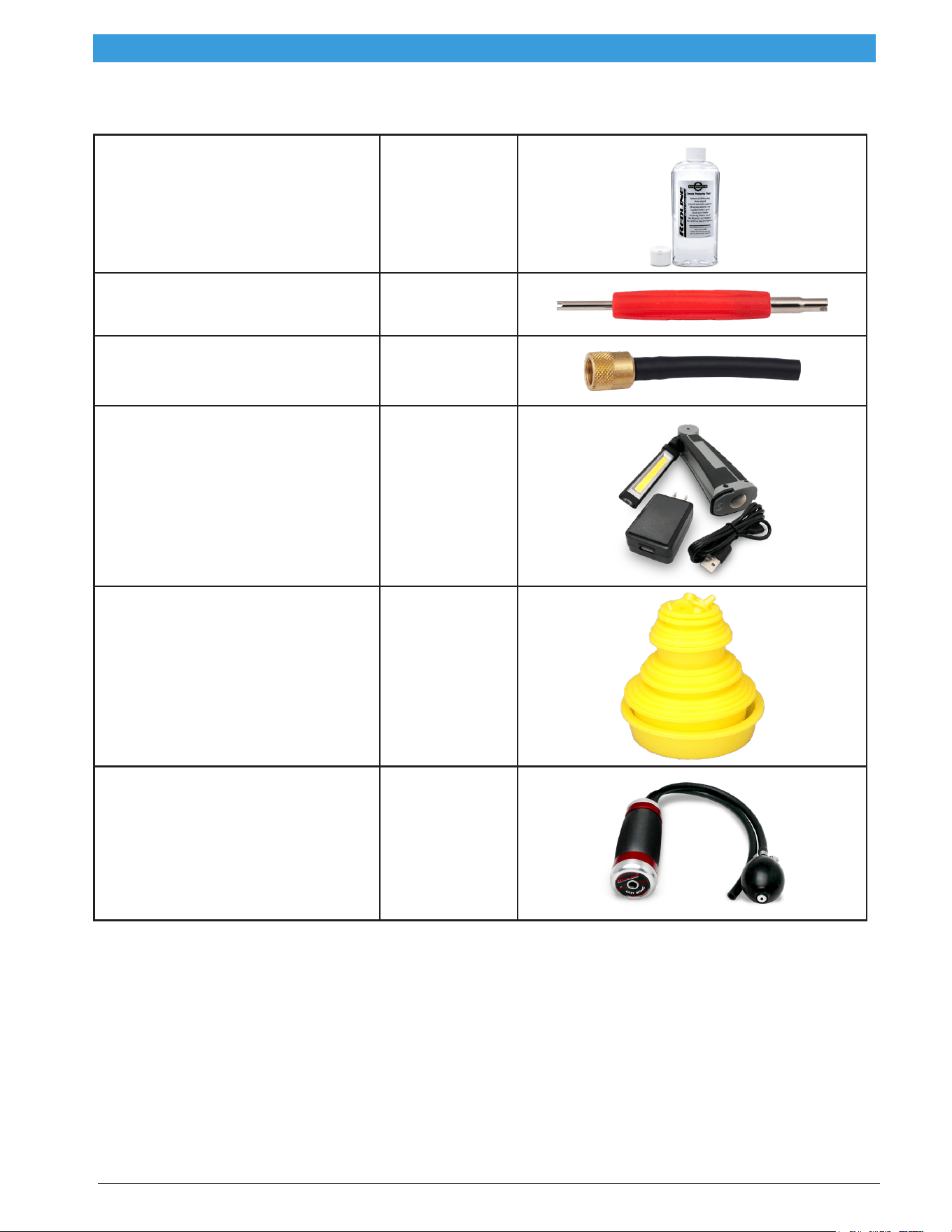
Accessories
OEM-Approved Vapor-
Producing Fluid
169500005
Vapor-producing uid will perform over
1,000 typical tests (500+ per bottle)
IMPORTANT: Contains no dye/contami-
nants
Schrader Valve Removal Tool 6522-5
EVAP Service Port Adapter 6522-4
Daylight Spectrum LED
Cordless Light
SMT-01
Bright white beam nds even the tiniest
wisps of vapor under the hood or chassis
Cap Plug Kit 6522-6
Seals a variety of openings to pressurize
system for testing
Easy INTAKE™ SMT-02
Award-winning Easy INTAKE™ is an
inflatable block off bladder with a
pressurized vapor pass-through that
allows technicians to test an entire
intake or exhaust system quickly and
easily
en
|
6
|
Operating Instructions |
SMT500 Leak Detector
SP01501467 | REV A | 4.2021
Bosch Automotive Service Solutions Inc
Setup
FILL/ADD VAPOR PRODUCING FLUID
1. Remove uid ll dipstick.
2. Pour vapor producing uid into uid ll port
until uid level is near top of the ll line on
the dipstick.
3. Replace uid ll dipstick
Do not overll.
Notes:
• First time ll requires approx. 2 oz (60 ml).
• Check uid level every 75–100 tests.
• Never use dyes, solvents, or other contaminants
in intake or exhaust systems. They may coat and/
or harm critical sensors and catalysts.
• Fill uid to maximum ll line on dipstick.
CONNECT TO POWER
This machine runs on a fully-charged 12-volt
battery.
1. Connect red lead (+) to battery’s positive
terminal.
2. Connect black lead (-) to chassis ground.
Do not connect to battery charger.
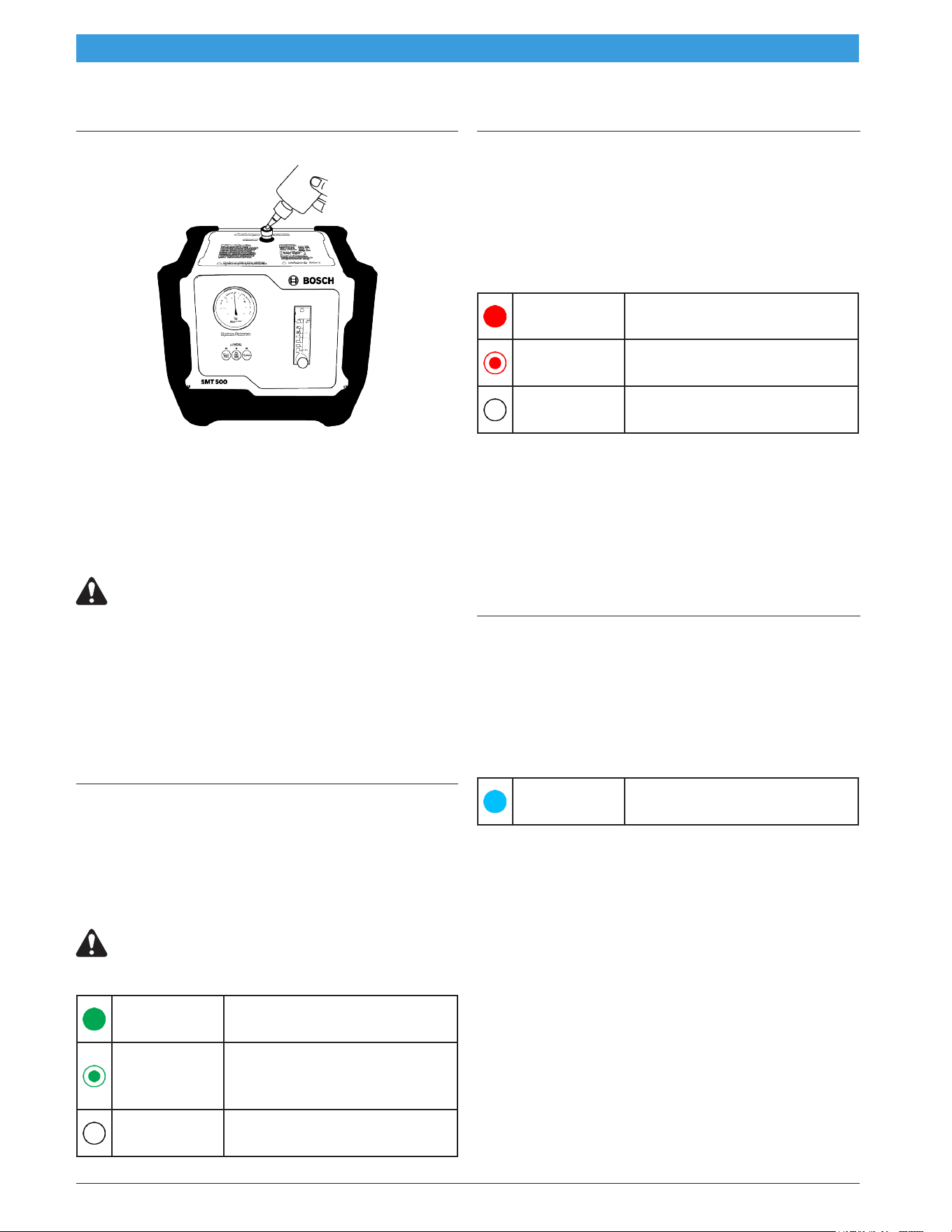
Power indicator light:
Solid green
light
Machine has adequate
power
Flashing
green light
Improper power; supplied
voltage is too high or too
low
No light
No power. See
Troubleshooting
Testing for Leaks
TESTING WITH SMOKE
1. Connect vapor output hose to system that
is to be tested. See Diagnostics section for
more detail.
2. Push vapor test button to begin a 5-minute
vapor cycle
Vapor indicator light:
Solid red
light
Vapor is being generated
Flashing
red light
See Troubleshooting
No light
No vapor is being
generated
3. Turn Flow Control Knob counter-clockwise
to release smoke / pressure
Note: Flow meter indicates ow and measures
leak size.
4. Use provided Halogen Inspection Light to
locate leaks
5. Perform repair(s) as needed
TESTING WITH AIR-ONLY
1. Connect vapor output hose to system that
is to be tested. See Diagnostics section for
more detail.
2. Push air-only test button to begin a 5-minute
vapor cycle.
Air-only indicator light:
Solid blue
light
Machine has adequate
power
3. Turn ow control knob counter-clockwise to
release pressure.
Note: Flow meter indicates ow and measures
leak.

SP01501467 | REV A | 4.2021
Bosch Automotive Service Solutions Inc
SMT500 Leak Detector
|
Operating Instructions
|
7
|
en
Verify Repairs
PERFORM DECAY / LEAK DOWN TEST
1. Pressurize the sealed system.
2. Lock out system by turning ow control knob
clockwise to the fully closed position.
OBSERVE PRESSURE GAUGE FOR DECAY
Pressure
holds
No leaks; repair complete
Pressure
decreases
Leak(s) exist; repair
necessary
NOTE: Not all systems are designed to be 100%
sealed.
Diagnostics
Intake System and Vacuum Leaks
This procedure will locate leaks in vacuum lines
as well as manifolds, EGR valves, oil seals,
gaskets, solenoids, o-rings, ducting, throttle
shafts, diaphragms, canisters, and more.
Note: For best results, test in a draft-free area.
1. Remove the air lter housing from ducting.
2. If the vehicle has a round inlet tube from the
air lter, place the cone adapter into the duct
toward the engine.
3. Put the vapor supply hose into cone adapter
to introduce vapor into the system.
4. Use daylight spectrum LED cordless light to
locate leaks.
Alternative method:
1. Select an appropriate vacuum line to access
the vacuum system (i.e. a brake booster
supply line before the check valve).
2. Seal all system openings.
• Air Intake must be sealed to prevent vapor
from leaking back through the intake.
• To seal the intake, use cap plugs, a latex
glove, or plastic wrap around the filter.
3. Put vapor output hose into cone adapter to
introduce vapor into the system.
4. Use daylight spectrum LED cordless light to
locate leaks.
EVAP Leaks
Leaks in the EVAP system, or fuel vapor recovery
system, are frequently the cause for check
engine lights. Using a diagnostic leak detector,
these leaks can now be quickly diagnosed and
repaired, making them protable services for
repair facilities.
1. To access the EVAP service port, remove the
green cap.
2. Remove Schrader valve using the Schrader
valve removal tool.
Note: Schrader valve has left-handed threads;
turn clockwise to remove.
3. Connect the EVAP service port adapter to
the service port.
4. Use a scan tool to close the vent solenoid
to close EVAP system from atmosphere. (If
vent solenoid does not close, intermittent
solenoid may have failed.)

en
|
8
|
Operating Instructions |
SMT500 Leak Detector
SP01501467 | REV A | 4.2021
Bosch Automotive Service Solutions Inc
5. Input vapor into the system through adapter.
6. Remove the fuel cap until dense vapor is
exiting the ller neck.
7. Replace the fuel cap and continue pumping
vapor into the system.
8. As the system lls with vapor and the system
pressure equalizes, observe the ow meter
and pressure gauge.
9. When pressure gauge reaches its maximum
pressure, the ow meter will indicate leak size.
Note: Flow meter will drop to zero if there are no
leaks.
10. Use the daylight spectrum LED cordless light
to inspect under the hood and trace the
route of the EVAP system on the underside
of the vehicle for leaks.
11. Repair the system as needed.
After all repairs have been made, retest the
system using the decay or leak down testing
method with air only.
12. Input air into EVAP system until fully
pressurized.
13. Lock out system by turning the ow control
knob to the fully closed position.
If leaks are repaired properly, system will hold
pressure.
If pressure decays or leaks exist, repeat above
procedures until all repairs are complete.
Exhaust Leaks
This test is most effective when exhaust system
is cold; thermal expansion may cause small leaks
to seal.
1. Insert Easy INTAKE™ into the end of the
tailpipe. If the vehicle has dual exhaust with
cross over system, plug the other tailpipe to
seal the system.
2. Put vapor output hose into Easy INTAKE™ to
introduce vapor into the system.
Note: A hot catalytic converter may consume
some of the smoke.
All testing is performed with the engine off.
Under-Dashboard Leaks
Many vehicles have a common vacuum line,
leading from the engine compartment through
the rewall, under the dashboard.
This line supplies vacuum to climate control
functions and other vacuum-operated systems.
1. Disconnect the vacuum line, under the hood,
at its source.
2. Input vapor into the vacuum line.
3. Observe the ow meter and pressure gauge
while changing the climate controls from
heat to vent, to defrost, etc.
Note: Change in the ow meter or pressure gauge
reading will indicate which system is leaking.
4. Set the climate control to the leaking system.
5. Use the daylight spectrum LED cordless light
to locate under-dash leaks.
Central locking system leak inspection is
performed in the same manner.
Activate control solenoids while introducing
vapor into the system.

SP01501467 | REV A | 4.2021
Bosch Automotive Service Solutions Inc
SMT500 Leak Detector
|
Operating Instructions
|
9
|
en
Maintenance
Check Fluid Level
1. Remove uid-ll plug from uid ll port.
2. Pour OEM-approved vapor agent into uid-
ll port until uid level is near top of the
uid-ll port.
3. Replace uid-ll plug.
Check uid level every 75–100 tests.
Clean Flow Meter
1. Disconnect air supply and power from the
machine.
2. Remove the ow meter’s top plug.
3. Invert the machine to remove ow meter ball.
4. Apply isopropyl/rubbing alcohol to a long
cotton swab to clean ow meter tube.
5. Use a dry cotton swab to dry ow meter tube.
6. Wipe ow meter ball clean with dry cloth.
Do not use alcohol / cleaners on ow
meter ball.
7. Reinstall the ow meter ball and the top plug.
Drain Vapor Hose
1. Elevate the machine
2. Allow the entire vapor hose to hang
downward.
3. Place a container beneath the nozzle to
capture uid.
Draining the vapor hose takes approximately 5
minutes.

en
|
10
|
Operating Instructions |
SMT500 Leak Detector
SP01501467 | REV A | 4.2021
Bosch Automotive Service Solutions Inc
Troubleshooting
Problem Solution
No green light
• Check polarity
• Ensure 12-volt battery is fully charged
• Reconnect power cables
Green light ashing
• Power supply must be between 11.5 and 14 VDC
• Connect to a fully charged 12-volt battery
• Never use battery charger as power source
Amber or red light ashing
• Open circuit/internal component
• Contact technical support
No air ow
• Open the ow control valve
• Ensure hoses are not kinked or pushed into machine
Insufcient vapor
• Check uid level
• Open the ow control valve
• Ensure hoses are not kinked or pushed into machine
Flow meter ball sticking
• Tap face of ow meter
• If problem persists, clean ow meter
Gauge bouncing or ow meter
bouncing
Drain vapor hose
High pressure reading Ensure hoses are not kinked or pushed into machine

SP01501467 | REV A | 4.2021
Bosch Automotive Service Solutions Inc
SMT500 Leak Detector
|
Operating Instructions
|
11
|
en
Notes

Bosch
Automotive Service Solutions Inc
Customer Service: 800-321-4889 Option 4, then 2
www.boschdiagnostics.com
SP01501467 | REV A | 4.2021