


SAVE THESE INSTRUCTIONS
This manual contains important safety and operating instructions.
Read all instructions and follow them with use of this product.
TABLE OF CONTENTS
Safety Guidelines P.4
Safety Information P.5
Product Speciÿcations P.3
Key Parts Diagram P.9
Glossary of Terms P.10
Assembly Instructions P.10
P.11 Operating Instructions
Maintenance P.15
Troubleshooting P.16
Warranty P.17
2 – English

Model No.
Operating Pressure
Fastener Type
Fastener Range
Magazine Capacity
Air Consumption
Air Inlet
Weighted sound impulse power leve
Emission sound pressure level
Weight
AT161002
70-120 psi
18 gauge staples
3/8 in. to 1-1/2 in.
105 staples
0.053 ft°/cycle at 100 psi
1/4 in. NPT
105.1 dBA
95.9 dBA
3.0 lbs.
l
PRODUCT SPECIFICATIONS
APPLICATIONS
You may use this tool for the purposes listed below:
• Finish and Trim (Interior and Exterior)
• Floor Underlayment
• Cabinet Work
• Casebacks
• Furniture
• Light Trim Moldings
• Fascia and Sofÿts
• Drawers
• Staircases
• Carpet installation
• Mirror and Picture Frames
• Crafts
• Lattice
3 – English
SAFETY GUIDELINES
Important Safety Information
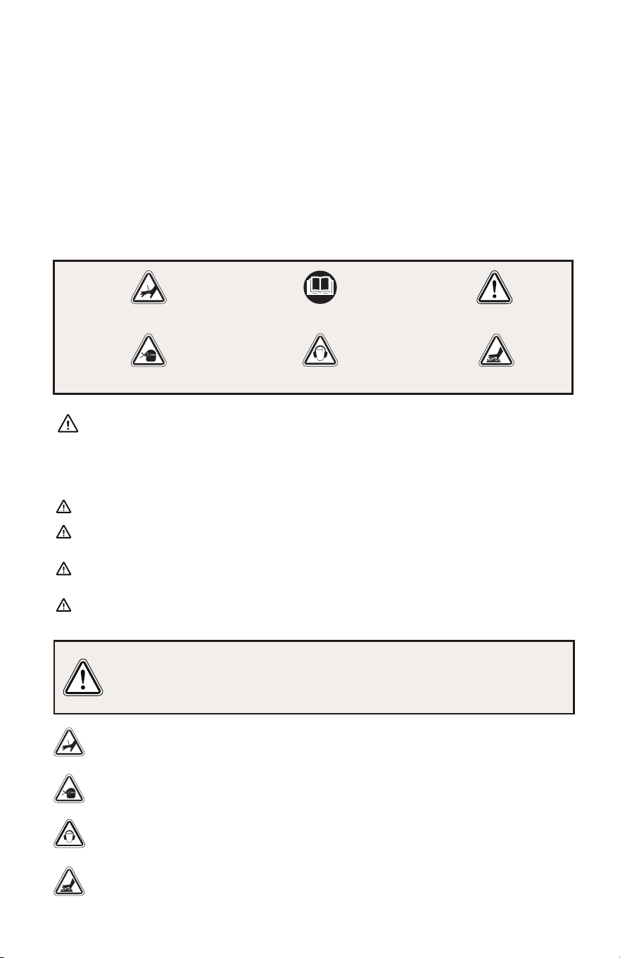
Safety Symbols and Meanings
indicates a hazard which, if not avoided, will result in death or serious injury.
indicates a hazard which, if not avoided, could result in death or
serious injury.
addresses practices not related to personal injury.
moderate injury.
indicates a hazard which, if not avoided, could result in minor or
DANGER
WARNING
CAUTION
NOTICE
The manufacturer cannot possibly anticipate every possible circumstance that might involve
a hazard. The warnings in this manual, and the tags and decals afÿxed to the
unit are, therefore, not all-inclusive. If you use a procedure, work method, or operating
technique that the manufacturer does not speciÿcally recommend, you must satisfy yourself
that it is safe for you and others. You must also make sure that the procedure, work
method, or operating technique that you choose does not render the compressor unsafe.
The safety alert symbol indicates a potential hazard to personal injury. A signal word
(DANGER, WARNING, or CAUTION) is used with the alert symbol to designate a degree or
level of hazard seriousness. A safety symbol may be used to represent the type of hazard.
The signal word NOTICE is used to address practices not related to personal injury.
Always wear hearing protection when using a tool. Failure to do so may result in
hearing loss.
DO NOT OPERATE THIS UNIT BEFORE YOU READ AND UNDERSTAND THIS
INSTRUCTION MANUAL FOR SAFETY, OPERATION, AND MAINTENANCE
INSTRUCTIONS.
Hot tool surfaces could result in serious injury. Allow tool to cool before touching.
Risk of serious eye injury. Always wear ANSI Z87.1 approved safety glasses when
using a tool. Do not spray any part of the body.
4 – English
WarningKeep Hands Away Operator's Manual
Hearing
Keep hands and body away from the discharge area of the tool.
Flying Objects Hot Surface

SAVE THESE INSTRUCTIONS WORK AREA
READ AND UNDERSTAND TOOL LABELS AND MANUAL. Failure to follow
warnings could result in DEATH or SERIOUS INJURY.
• Keep your work area clean and well lit. Cluttered benches and dark areas invite accidents.
• Do not operate power tools in explosive atmospheres, such as in the presence of
ammable liquids, gases, or dust. Power tools create sparks which may ignite the dust
or fumes.
• Keep bystanders, children, and visitors away while operating a power tool. Distractions
can cause you to lose control.
PERSONAL SAFETY
TOOL USE AND CARE
• Eye protection which conforms to ANSI speciÿcations and provides protection against
ying particles both from the FRONT and SIDE should ALWAYS be worn by the
operator and others in the work area when loading, operating or servicing this tool.
Eye protection is required to guard against ying fasteners and debris, which could
cause severe eye injury.
• The employer and/or user must ensure that proper eye protection is worn. We
recommend Wide Vision Safety Mask for use over eyeglasses or standard safety
glasses that provide protection against ying particles both from the front and side.
Always wear eye protection with side shields marked to comply with ANSI Z87.1.
• Additional safety protection will be required in some environments. For example, the
working area may include exposure to noise level which can lead to hearing damage.
The employer and user must ensure that any necessary hearing protection is provided
and used by the operator and others in the work area. Some environments will require
the use of head protection equipment. When required, the employer and user must
ensure that head protection conforming to ANSI Z89.1-1997 is used.
• Stay alert, watch what you are doing and use common sense when operating a power
tool. Do not use tool while tired or under the inuence of drugs, alcohol, or medication.
A moment of inattention while operating power tools may result in serious personal
injury.
• Dress properly. Do not wear loose clothing or jewelry. Contain long hair. Keep your
hair, clothing, and gloves away from moving parts. Loose clothes, jewelry, or long hair
can be caught in moving parts.
• Keep ÿngers away from trigger when not driving fasteners to avoid accidental ÿring.
• Do not overreach. Keep proper footing and balance at all times. Proper footing and
balance enables better control of the tool in unexpected situations.
• Use safety equipment. Always wear eye protection. Dust mask, nonskid safety shoes,
hard hat, or hearing protection must be used for appropriate conditions.
• Do not use on a ladder or unstable support. Stable footing on a solid surface enables
better control of the tool in unexpected situations.
• Do not force tool. Use the correct tool for your application. The correct tool will do the
job better and safer at the rate for which it is designed.
• Do not use tool if trigger does not actuate properly. Any tool that cannot be controlled
with the trigger is dangerous and must be repaired.
SAFETY INFORMATION
5 – English

6 – English
• Check operation of the workpiece contact mechanism frequently. Do not use the tool if
the workpiece contact mechanism is not working correctly as accidental driving of a 、
fastener may result. Do not interfere with the proper operation of the workpiece
contact mechanism.
• Store idle tools out of the reach of children and other untrained persons. Tools are
dangerous in the hands of untrained users.
• Maintain tools with care. Follow maintenance instructions. Properly maintained tools
are easier to control.
• Check for misalignment or binding of moving parts, breakage of parts, and any other
condition that may affect the tool’s operation. If damaged, have the tool serviced
before using. Many accidents are caused by poorly maintained tools.
• Use only fasteners that are recommended for your model.
• Keep the tool and its handle dry, clean and free from oil and grease. Always use a
clean cloth when cleaning. Never use brake uids, gasoline, petroleum-based
products, or any strong solvents to clean your tool. Following this rule will reduce the
risk of loss of control and deterioration of the enclosure plastic.
SERVICE
• Tool service must be performed only by qualiÿed repair personnel. Service or
maintenance performed by unqualiÿed personnel may result in a risk of injury.
• When servicing a tool, use only identical replacement parts. Follow instructions in the
Maintenance section of this manual. Use of unauthorized parts or failure to follow
Maintenance instructions may create a risk of injury.
• Know your pneumatic tool. Read operator’s manual carefully. Learn its applications
and limitations, as well as the speciÿc potential hazards related to this tool. Following
this rule will reduce the risk of electric shock, ÿre, or serious injury.
• Always wear eye protection with side shields marked to comply with ANSI Z87.1.
Failure to do so could result in objects being thrown into your eyes resulting in
possible serious injury.
• Protect your lungs. Wear a face or dust mask if the operation is dusty. Following this
rule will reduce the risk of serious personal injury.
• Protect your hearing. Wear hearing protection during extended periods of operation.
Following this rule will reduce the risk of serious personal injury.
• Make sure the hose is free of obstructions or snags. Entangled or snarled hoses can
cause loss of balance or footing and may become damaged.
• Use the tool only for its intended use. Do not discharge fasteners into open air.
• Use the pneumatic tool only for the purpose for which it was designed.
• Use only the fasteners recommended for this tool. Use of the wrong fasteners could
result in poor fastener feeding, jammed fasteners, and nails leaving the tool at erratic
angles. If fasteners are not feeding smoothly and properly, discontinue their use
immediately. Jammed and improperly feeding fasteners could result in serious
personal injury.
• Never use this tool in a manner that could cause a fastener to be directed toward
anything other than the workpiece.
• Do not use the tool as a hammer.
• Always carry the tool by the handle. Never carry the tool by the air hose.

7 – English
OPERATION
• Always assume that the tool contains fasteners.
• Do not carry the tool from place to place holding the trigger. Accidental discharge
could result.
• Always handle the tool with care:
a. Respect the tool as a working implement.
b. Never engage in horseplay.
c. Never pull the trigger unless nose is directed toward the work.
d. Keep others a safe distance from the tool while tool is in operation as accidental
actuation may occur, possibly causing injury.
• Choice of triggering method is important. Check manual for triggering options.
• Pneumatic tools are designed for single-hand use. Do not hold the tool by the front of
the magazine. Do not put hands, head, or other parts of your body near the bottom of
the magazine where the fastener exits the tool, as serious personal injury could result.
• Do not point the tool toward yourself or anyone whether it contains fasteners or not.
• Do not actuate the tool unless you intend to drive a fastener into the workpiece.
• Always ensure that the workpiece contact is fully positioned above the workpiece.
Positioning the workpiece contact only partially above the workpiece could cause the
fastener to miss the workpiece completely and result in serious personal injury.
• Do not drive fasteners near edge of material. The workpiece may split causing the
fastener to ricochet, injuring you or a co-worker. Be aware that the fastener may follow
the grain of the wood, causing it to protrude unexpectedly from the side of the work
material.
• Keep hands and body parts clear of immediate work area. Hold workpiece with clamps
when necessary to keep hands and body out of potential harm. Be sure the workpiece
is properly secured before pressing the nailer against the material. The workpiece
contact may cause the work material to shift unexpectedly.
• Keep face and body parts away from back of the tool cap when working in restricted
areas. Sudden recoil can result in impact to the body, especially when nailing into hard
or dense material.
• During normal use the tool will recoil immediately after driving a fastener. This is a
normal function of the tool. Do not attempt to prevent the recoil by holding the nailer
against the work. Restriction to the recoil can result in a second fastener being driven
from the nailer. Grip the handle ÿrmly, let the tool do the work and do not place second
hand on top of tool or near exhaust at any time. Failure to heed this warning can result
in serious personal injury.
• Do not drive fasteners on top of other fasteners or with the tool at an overly steep
angle as this may cause deection of fasteners which could cause injury.
• Do not drive fasteners close to the edge of the workpiece as the wood may split,
allowing the fastener to be deected possibly causing injury.
• Do not alter or modify this tool from the original design or function without approval
from the manufacturer.
• Always be aware that misuse and improper handling of this tool can cause injury to
yourself and others.
• Never clamp or tape the trigger or workpiece contact in an actuated position.
• Never leave a tool unattended with the air hose attached.
• Do not operate this tool if it does not contain a legible warning label.
• Do not continue to use a tool that leaks air or does not function properly.
8 – English
AIR SUPPLY AND CONNECTIONS
• Do not use oxygen, combustible gases or bottled gases as a power source for this tool
as tool will explode, possibly causing injury or death.
• Do not use with an air compressor which can potentially exceed 200 psi as tool may
burst, possibly causing injury.
• The connector on the tool must not hold pressure when air supply is disconnected. If
an incorrect ÿtting is used, the tool can remain charged with air after disconnecting
and thus will be able to drive a fastener even after the air line is disconnected, possibly
causing injury.
• Always disconnect air supply:
a. Before making adjustments
b. When servicing the tool
c. When clearing a jam
d. When tool is not in use
e. When moving to a different work area, as accidental actuation may occur, possibly
causing injury.
• Do not load the tool with fasteners when any one of the operating controls is activated.
When loading tool:
• Never place a hand or any part of body in fastener discharge area of tool.
• Never point tool at anyone.
• Do not pull the trigger or depress the workpiece contact as accidental actuation may
occur, possibly causing injury.
• Refer to them frequently and use them to instruct others who may use this tool. If you
loan someone this tool, loan them these instructions also.
Do not use this product if it is not completely assembled or if any parts
appear to be missing or damaged. Use of a product that is not properly and
completely assembled or with damaged or missing parts could result in
serious personal injury.
LOADING TOOL
SAVE THESE INSTRUCTIONS
ASSEMBLY
WARNING:
Do not use any attachments or accessories not recommended by the
manufacturer of this tool. The use of attachments or accessories not recommended can
result in serious personal injury.
9 – English
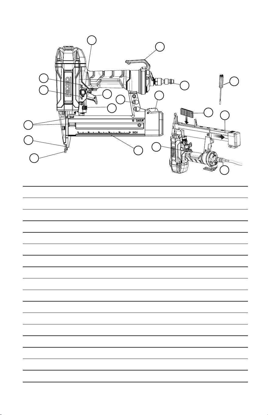
KEY PARTS DIAGRAM
E.
D.
B.
A.
H.
I.
J.
F.
G.
C.
K.
N.
O.
P.
L.
M.
Q.
G
D
B
M
E
L
N
Q
F
H
O
P
I
A
J
K
E
C
Actuation mode selector
Quick connect swivel connector
Belt hook
Latch
Bottom-loading magazine
Depth-of-drive adjustment
Workpiece contact with no-mar pad
NOSE
Reload indicator
Selectable trigger
No-mar pad storage
Air hose connector (not included)
Staples (not included)
Actuation mode selector (depress to allow selector to rotate)
Single sequential actuation
Contact actuation
Screwdriver (not included)

10 – English
GLOSSARY OF TERMS
Activate (operating controls)
To move an operating control so that it is in a position that allows the tool to be actuated
or that satisÿes one requirement for the tool to be actuated.
Actuate (tool)
To cause movement of the tool component(s) intended to drive a fastener.
Actuation system
The use of a trigger, workpiece contact, and/or other operating control, separately or in
some combination or sequence, to actuate the tool.
• Single sequential actuation
An actuation system in which there is more than one operating control and the
operating controls must be activated in a speciÿc sequence to actuate the
tool. Additional actuation can occur when a speciÿc operating control, other
than a workpiece contact, is released and re-activated.
• Contact actuation
An actuation system in which there is more than one operating control and the
operating controls can be activated in any sequence to actuate the tool.
Additional actuation can occur when any operating control is released and
re-activated.
Air inlet port
In an air tool, the opening to which the compressed air supply is connected, usually by
means of a threaded ÿtting.
Fastener
A staple, pin, brad, nail, or other fastening device which is designed and
manufactured for use in the tools within the scope of this standard.
Jam
An obstruction in the feed or drive areas of the tool.
Maximum air pressure
The maximum allowable pressure of the compressed air, as speciÿed by the manufactur-
er, for operating a tool.
Operating control
A control that separately, or as part of an actuation system, can cause the actuation of a
tool.
Trigger
A tool operating control activated by a tool operator’s ÿngers.
Workpiece
The intended object into which a fastener is to be driven by a tool.
Workpiece contact
An operating control element or assembly on the tool intended to be activated by the
material to be fastened.
PREPARING THE TOOL FOR USE
This is an oil-free tool, therefore lubrication is not required. However, the occasional
addition of air tool lubrication into the air ÿtting on the tool will not adversely affect
performance or harm the tool.
Before connecting the tool, check the air compressor gauge to be sure it is functioning
within the proper range of 70-120 psi.
NO-MAR PAD
The no-mar pad attached to the workpiece contact
helps prevent marring and denting when working
with softer woods.
BELT HOOK
The hook will rotate to either side of the tool and can be used to hang the tool from a
belt when disconnected and not in use.
Do not use oxygen, combustible gases or bottled gases as a power
source for this tool. The tool will explode and cause death or serious injury.
DANGER:
WARNING: Do not allow familiarity with tools to make you careless. Remember
that a careless fraction of a second is sufÿcient to inict severe injury.
WARNING: Disconnect the tool from the air supply before removing or replacing
the no-mar pad. Failure to do so could result in serious personal injury.
The no-mar pad can be removed by pulling it down and away from the workpiece
contact. To replace the no-mar pad, ÿt it into place over the workpiece contact and
push up at the back to reseat.
On-board storage for the no-mar pad is located on the magazine of the tool. Two extra
no-mar pads are provided in the on-board storage area.
WARNING: Disconnect the tool from the air supply before leaving the work area,
moving the tool to another location, or handing the tool to another person. Failure to
do so could result in serious personal injury.
WARNING: Always wear eye protection with side shields marked to comply with
ANSI Z87.1. Failure to do so could result in objects being thrown into your eyes
resulting in possible serious injury.
WARNING: Disconnect the tool from the air supply before leaving the work area,
moving the tool to another location, or handing the tool to another person. Failure
to do so could result in serious personal injury.
WARNING: Do not use any attachments or accessories not recommended by the
manufacturer of this product. The use of attachments or accessories not recommended
can result in serious personal injury.
WARNING: Always wear eye protection. Eye protection does not ÿt all operators
in the same way. Make sure the eye protection chosen has side shields or provides
protection from ying debris both from the front and sides.
11 – English
OPERATION
G
H
K
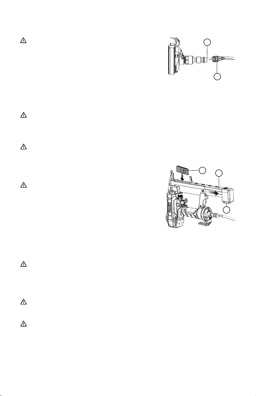
CONNECTING THE TOOL TO AN AIR SUPPLY
12 – English
This tool is designed to operate on clean, dry
compressed air at regulated pressures between
70 and 120 psi . The correct air pressure is the
lowest pressure that will do the job.
Do not use oxygen, combustible
gases or bottled gases as a power source for this tool.
The tool will explode and cause death or serious injury.
DANGER:
WARNING:
Always use a coupling that discharges all the compressed air in the
tool at the time the ÿtting or hose coupling is disconnected. Using a coupling that does
not discharge the compressed air could cause unintended operation and serious
personal injury.
WARNING: Do not climb rigging or scaffolding while carrying a tool that is
connected to an air hose. Doing so could result in serious personal injury. Connect the
tool to the air supply with a 1/4 in. female quick connector.
LOADING THE TOOL WITH STAPLES
• Connect the tool to the air supply.
• While holding the tool upside down and with the nose
pointed away from you, depress the latch located at
the rear of the magazine and slide the magazine open.
WARNING: The tool’s driving mechanism may
cycle when the tool is ÿrst connected to the air
supply. Always connect the tool to a pressurized
air supply before loading fasteners to prevent injury
from unintended cycling. Always make sure the
tool’s magazine is empty at the beginning of each
work session, before connecting to an air supply.
DRY-FIRE LOCKOUT
The dry-ÿre lockout feature keeps the tool from operating when fasteners are low in the
magazine to prevent missing fasteners in the nail pattern and extend tool life.
WARNING: Keep the tool pointed away from yourself and others when loading
staples. Failure to do so could result in possible serious personal injury.
• Drop a strip of staples into the magazine. Be sure to insert the staples crown ÿrst so
that the open end points away from the magazine.
• Push the magazine cover closed until it securely snaps into place.
WARNING: Use only the staples recommended for use with this tool (refer to the
Fastener Guide). The use of any other staples can result in tool malfunction, leading
to serious injuries.
WARNING: Never load staples with the workpiece contact or trigger activated.
Doing so could result in possible serious personal injury.
B
L
M
E
D
NOTE: Air pressure that is higher than 120 PSI may damage the tool. The tool and
air hose must have a hose coupling that allows all pressure to be removed from the tool
when the coupling is disconnected.
13 – English
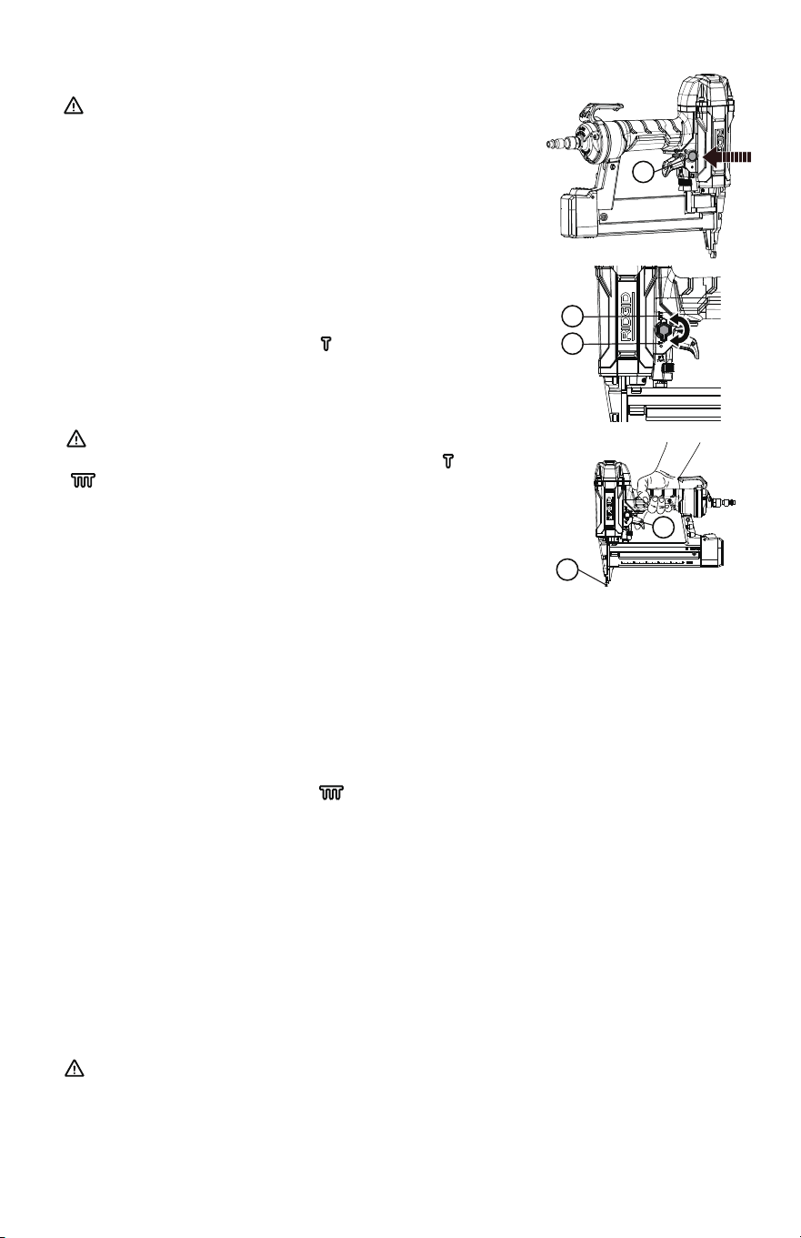
USING THE SELECTABLE TRIGGER
SINGLE SEQUENTIAL ACTUATION MODE
CONTACT ACTUATION MODE
• Reconnect the tool to the air supply.
• Grip the tool ÿrmly to maintain control. Position the
nose of the tool onto the work surface.
• Push the tool against the work surface to depress the workpiece contact.
• Squeeze the trigger to drive a fastener.
• Allow the tool to recoil away from the work surface as the fastener is driven.
• Always remove your ÿnger from the trigger when the desired number of staples has
been driven.
WARNING: Never wedge or hold back the workpiece
contact mechanism during operation of the tool. Doing
so could result in possible serious injury. This tool is shipped
from the factory with a selectable trigger set in the Single
Sequential Actuation mode. The selectable trigger can also
be set for Contact Actuation mode.
WARNING: During normal use the tool will recoil immediately after driving a
fastener. This is a normal function of the tool. Do not attempt to prevent the recoil by
holding the tool against the work. Restriction to the recoil can result in a second
fastener being driven from the tool. Grip the handle ÿrmly, let the tool do the work, and
do not place second hand on top of tool or near exhaust at any time. Failure to heed
this warning can result in serious personal injury.
N
J
G
P
O
Single sequential actuation provides the most accurate
fastener placement.
• Disconnect the tool from the air supply.
• Depress the actuation mode selector.
• Rotate the selector to Position ( ).
• Release the actuation mode selector.
WARNING: The nailer will not function properly if the
selector is not securely seated in either position ( ) or
( ). Always assure the selector is seated properly to avoid
an unexpected fastener discharge and possible serious
personal injury.
Contact actuation allows very fast repetitive fastener placement.
• Disconnect the tool from the air supply.
• Depress the actuation mode selector.
• Rotate the selector to Position ( ).
• Release the actuation mode selector.
NOTE: In Contact Actuation Mode, the tool may also be operated by depressing the
workpiece contact against the surface and squeezing the trigger.
NOTE: The actuation mode selector is spring loaded and held
in position by locking tab to prevent movement during operation.
NOTE: The actuation mode selector is spring loaded and held in position by locking tab to
prevent movement during operation.
• Reconnect the tool to the air supply.
• Grip the tool ÿrmly to maintain control.
• Squeeze and hold the trigger. Push the tool against the work surface to depress the
workpiece contact and drive a fastener.
• Allow the tool to recoil away from the work surface as the fastener is driven.
• Always remove your ÿnger from the trigger when the desired number of staples has
been driven.
14 – English
SETTING THE AIR PRESSURE
DEPTH-OF-DRIVE ADJUSTMENT
The amount of air pressure required will depend on the size of the fastener and the
workpiece material.
Begin testing the depth of drive by driving a test fastener into the same type of
workpiece material used for the actual job.
Drive a test fastener with the air pressure set at 90-95 psi. Raise or lower the air pressure
to ÿnd the lowest setting that will perform the job with consistent results.
It may be possible to achieve the desired depth with air pressure adjustments alone. If
ÿner adjustments are needed, use the depth of drive adjustment on the tool.
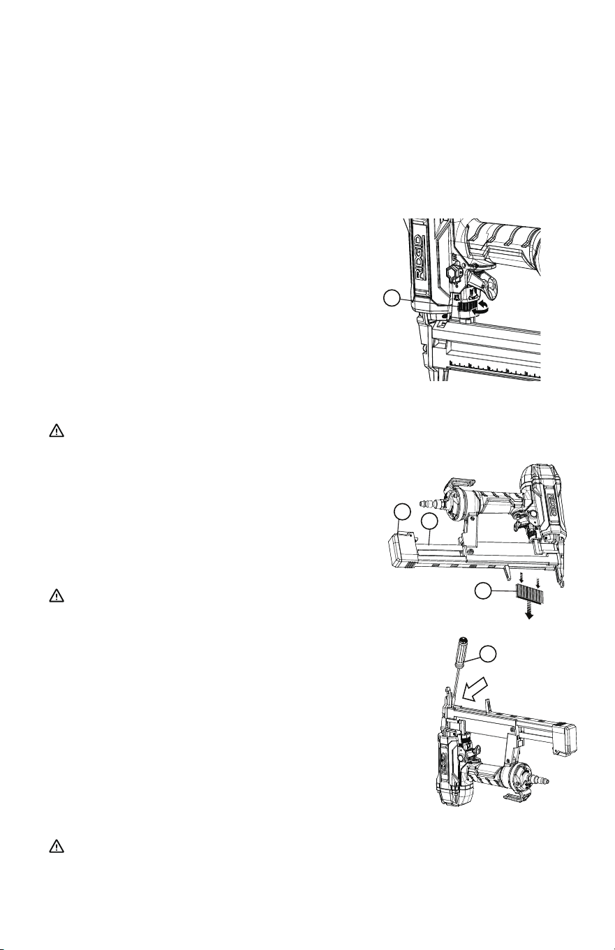
The driving depth of the staple may be adjusted. It is
advisable to test the depth on a scrap workpiece to
determine the required depth for the application.
To determine depth-of-drive, ÿrst adjust the air
pressure and drive a test staple. To achieve the desired
depth, use the depth-of-drive adjustment on the tool.
• Disconnect the tool from the air supply.
• Turn the depth selector left or right to change the
driving depth.
• Reconnect the tool to the air supply.
• Drive a test staple after each adjustment until the
desired depth is set.
WARNING: Disconnect the tool from the air supply before removing staples or
clearing a jammed fastener. Failure to do so could result in serious personal injury.
REMOVING STAPLES FROM THE TOOL
• Disconnect the tool from the air supply.
• While holding the tool upside down, depress the latch
located at the rear of the magazine and slide the
magazine open.
• Rotate the tool to the normal operating position,
allowing the staple strip to drop out of the magazine.
WARNING: Disconnect the tool from the air supply
before removing staples. Failure to do so could result
in serious personal injury.
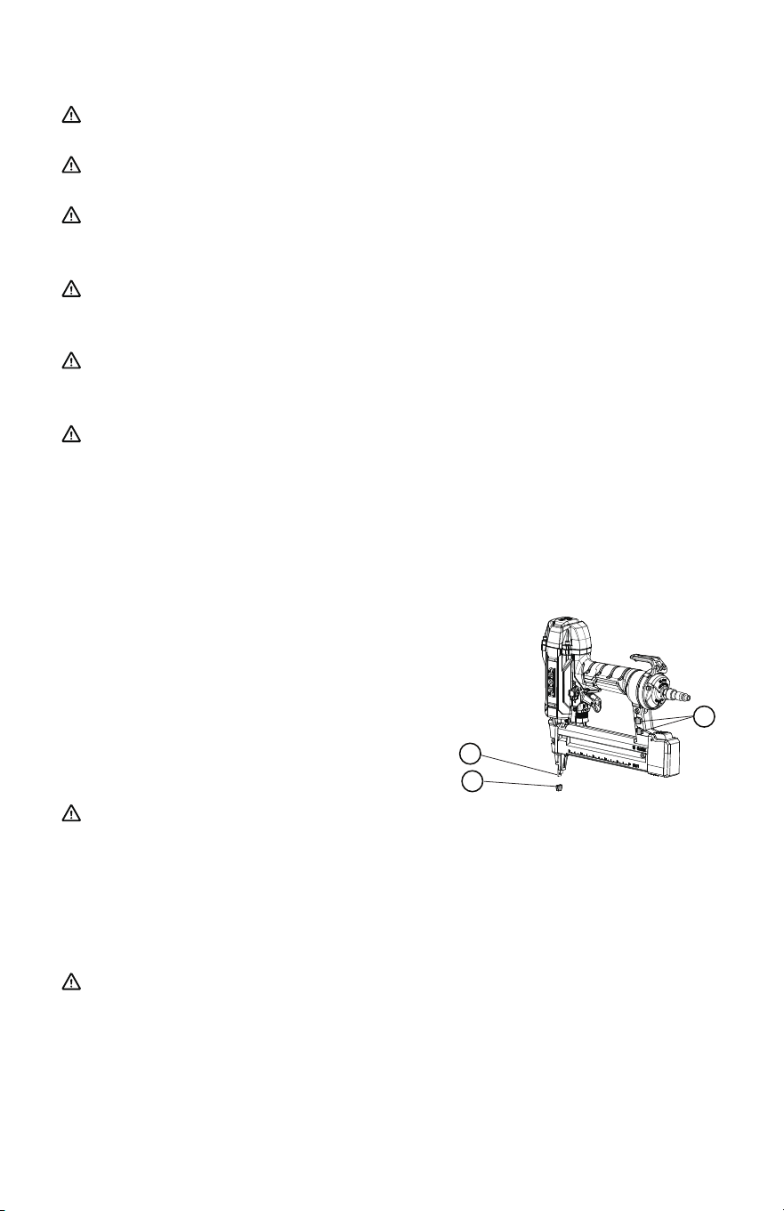
CLEARING A JAMMED FASTENER
If a fastener becomes jammed in the tool, disconnect
the air hose and keep the tool pointed away from
you while clearing the jam.
• Open the magazine and remove the fasteners from the tool.
• Insert a at blade screwdriver into the driving
mechanism and push the driver mechanism back,
freeing the fastener jam.
• Remove the bent fastener.
• Reconnect the tool to the air supply.
• Reinsert fasteners and close the magazine.
WARNING: Disconnect the tool from the air supply before clearing a jammed
fastener. Failure to do so could result in serious personal injury.
D
E
M
Q
F

15 – English
MAINTENANCE
GENERAL MAINTENANCE
Avoid using solvents when cleaning plastic parts. Most plastics are susceptible to
damage from various types of commercial solvents and may be damaged by their use.
Use clean cloths to remove dirt, dust, oil, grease, etc.
LUBRICATION
The cylinder, o-ring, and piston ring in this tool are lubricated with a sufÿcient amount of
high grade lubricant for the life of the unit under normal operating conditions. Therefore,
no further lubrication is required.
COLD WEATHER OPERATION
For cold weather operation, near and below freezing, the moisture in the air line may
freeze and prevent tool operation. We recommend the use of air tool lubricant or
permanent antifreeze (ethylene glycol) as a cold weather lubricant.
NOTICE: Do not store tools in a cold weather environment to prevent frost or ice
formation on the tools’ operating valves and mechanisms that could cause tool failure.
NOTE: Some commercial air line drying liquids are harmful to O-rings and seals. Do not
use these low temperature air dryers without checking compatibility.
AIR SUPPLY PRESSURE AND VOLUME
Air volume is as important as air pressure. The air volume supplied to the tool may be
inadequate because of undersize ÿttings and hoses, or from the effects of dirt and water
in the system. Restricted air ow will prevent the tool from receiving an adequate volume
of air, even though the pressure reading is high. The results will be a slow operation or
reduced driving power. Before evaluating tool problems for these symptoms, trace the air
supply from the tool to the supply source for restrictive connectors, low points
containing water and anything else that would prevent full volume ow of air to the tool.
REQUIRED DAILY CHECKLIST
With the dry-re lockout disengaged, perform the steps below:
• Disconnect the air supply from the tool and remove all fasteners.
• Check all screws, nuts, bolts, and pins on the tool. If any of these are loose, they must
be tightened with the appropriate size wrench.
• If your tool is equipped with a dry-ÿre lockout mechanism, then you will need to
disengage this feature by opening the magazine slightly or retracting the bypass pusher.
WARNING: When servicing use only identical RIDGID replacement parts. Use of
any other parts may create a hazard or cause product damage.
WARNING: Always wear eye protection with side shields marked to comply with
ANSI Z87.1. Failure to do so could result in objects being thrown into your eyes
resulting in possible serious injury.
WARNING: Disconnect the tool from the air supply before performing maintenance.
Failure to do so could result in serious personal injury.
WARNING: Do not at any time let brake uids, gasoline, petroleum-based products,
penetrating oils, etc., come in contact with plastic parts. Chemicals can damage,
weaken or destroy plastic which may result in serious personal injury.
• Press the workpiece contact against a workpiece to ensure that it moves smoothly.
• With the workpiece contact depressed, pull the trigger. The trigger should move
smoothly, without binding.
• Select sequential actuation mode ( ).
• While the tool is not loaded, connect the appropriate air supply (at 70 PSI) to the tool.
• Begin inspection:
a. Without pulling the trigger, press the workpiece contact against a workpiece several
times. The tool must not actuate.

16 – English
TROUBLESHOOTING
2. Worn or damaged O-rings
or seals
1. Loose screws 1. Tighten screws
2. Install Overhaul Kit
2. Worn or damaged O-rings
or bumper
1. Loose screws 1. Tighten screws
2. Install Overhaul Kit
1. Inadequate air supply
2. Inadequate lubrication
3. Worn or damaged O-rings
or bumper
1. Verify adequate air supply
2. Lubricate tool
3. Install Overhaul Kit
1. Incorrect fasteners
2. Damaged fasteners
3. Loose magazine
4. Dirty magazine
5. Worn or damaged driver
1. Verify that fasteners are the
correct size
2. Replace fasteners
3. Tighten screws
4. Clean magazine
5. Install Driver Maintenance Kit
Air leak near
the top of the
tool or in the
trigger area
Air leak near
the bottom
of the tool
Tool does
nothing or
operates
sluggishly
Tool jams
frequently
PROBLEM POSSIBLE CAUSE CORRECTIVE ACTION
This product has a 90-Day Satisfaction Guarantee Policy,
as well as a Three-year Limited Warranty.
For Warranty and Policy details, please go to REGISTER.RIDGIDAIR.COM
or call (toll free) 1 (866) 874-3443.
b. With the workpiece contact not engaged on the workpiece, point the tool down and
away in a safe direction and pull the trigger several times. Hold the trigger in this
position for a minimum of 5 seconds. The tool must not actuate.
c. Press the workpiece contact ÿrmly against the workpiece and pull the trigger. The
tool must actuate.
d. With the workpiece contact still depressed, release the trigger. The driver must return
to its up position.
• Select contact actuation mode ( ).
• Begin inspection:
a. With the workpiece contact not engaged on the workpiece, point the tool down and
away. Pull the trigger. The tool must not actuate.
b. Fully depress the trigger and push the workpiece contact against a workpiece. The
tool must actuate.
• Disconnect the air supply from the tool.
• If the tool successfully meets all the requirements in this checklist, it is ready for use.
Set the trigger on the tool to operate in the manner that best ÿts your application.
• Set the depth of drive according to the Depth of Drive Adjustment section in this
manual. Repeat this checklist before using the tool each day, or if the tool is dropped
or damaged in any way.

17 – English
(b) reviewing and completing the Warranty Claim Form.
(c) The Manufacturer will provide free replacement parts for the RIDGID® Pneumatic
Tools, which may be shipped to the owner's address.
However, the Manufacturer will have no warranty obligations with respect to a returned
RIDGID® Pneumatic Tools, including but not limited to costs of return shipping to
owner, if the Manufacturer determines, in its sole discretion after examination of the
returned RIDGID® Pneumatic Tools, that this 3-Year Limited Warranty does not apply to
the RIDGID® Pneumatic Tools for any of the reasons set
forth in the What is Not Covered Section above.
Service Communications
All 3-Year Limited Warranty communications should be directed to the Manufacturer by
calling toll-free 1 (866) 874-3443.
RIDGID Pneumatic Tools 3-Year Limited Warranty
What is Covered?
The 3-Year Limited Warranty is only applicable to the original purchaser and may not be
transferred. These programs only cover wear and tear or failure of the tool arising under
normal usage and proper maintenance. They do not cover any malfunction, failure or
defect resulting from misuse, abuse, neglect, alteration or modiÿcation of the product.
Any damage or malfunction inicted upon the tool by the user or other external sources,
or any failure to comply with the warnings and instructions in the operator’s manual is
not covered.
What is Not Covered?
The 3-Year Limited Warranty is only applicable to the original purchaser and may not be
transferred. These programs only cover wear and tear or failure of the tool arising under
normal usage and proper maintenance. They do not cover any malfunction, failure or
defect resulting from misuse, abuse, neglect, alteration or modiÿcation of the product.
Any damage or malfunction inicted upon the tool by the user or other external sources,
or any failure to comply with the warnings and instructions in the operator’s manual is
not covered.
How to Obtain Replacement Parts
If you believe the RIDGID® 6 Pneumatic Tools may not be operating as intended, you
may contact the Manufacturer at 1 (866) 874-3443 or REGISTER.RIDGIDAIR.COM
The Manufacturer’s warranty obligations are conditioned on the owner:
(a) notifying by calling the number above during the Warranty Period and providing a
description of the alleged failure with corresponding images.

18 – English
Additional Limitations
EXCEPT AS OTHERWISE STATED IN THIS LIMITED WARRANTY, THE MANUFACTURER
DISCLAIMS ALL WARRANTIES, EXPRESS, IMPLIED, OR STATUTORY, INCLUDING BUT
NOT LIMITED TO THE IMPLIED WARRANTIES OF MERCHANTABILITY AND FITNESS
FOR A PARTICULAR PURPOSE, TO THE MAXIMUM EXTENT PERMITTED BY
APPLICABLE LAW. THE MANUFACTURER ALSO LIMITS THE DURATION OF ANY
IMPLIED WARRANTIES TO THE SAME DURATION AS THIS LIMITED WARRANTY.
IN ADDITION TO THE WARRANTY DISCLAIMERS ABOVE, THE MANUFACTURER
SHALL NOT BE LIABLE FOR ANY CONSEQUENTIAL, INCIDENTAL, EXEMPLARY, OR
SPECIAL DAMAGES,
INCLUDING LOST PROFITS, ARISING FROM OR RELATING TO THIS LIMITED
WARRANTY OR THE PRODUCT. THE MANUFACTURER’S TOTAL CUMULATIVE
LIABILITY ARISING FROM OR RELATED TO THIS LIMITED WARRANTY OR THE
PRODUCT SHALL NOT EXCEED THE AMOUNT ACTUALLY PAID FOR THE PRODUCT
BY THE ORIGINAL PURCHASER.
STATE OR NON-U.S. LAW: SOME STATES AND/OR NON-U.S. JURISDICTIONS DO
NOT ALLOW LIMITATIONS ON HOW LONG AN IMPLIED WARRANTY LASTS OR
EXCLUSIONS/LIMITATIONS ON INCIDENTAL OR CONSEQUENTIAL DAMAGES, SO
THE ABOVE LIMITATIONS MAY NOT APPLY TO YOU. THIS WARRANTY GIVES YOU
SPECIFIC LEGAL RIGHTS, AND YOU MAY ALSO HAVE OTHER RIGHTS WHICH VARY
FROM STATE TO STATE OR FROM JURISDICTION TO JURISDICTION. THE
DISCLAIMERS, EXCLUSIONS, AND LIMITATIONS OF LIABILITY UNDER THIS LIMITED
WARRANTY WILL NOT APPLY TO THE EXTENT PROHIBITED BY APPLICABLE LAW.
