Save This Manual
for
Future Reference
Two-Stage
Snow
Blower
Operator's Manual
MODEL NUMBER
D 1005487565
D 1005425223
D 1005425207
SERIAL
NUMBER
PURCHASE
DATE
Both model number and serial
number may be found on the
main label.
You
should record
both
of
them in a safe place
for
future
use.
FOR
YOUR
SAFETY
READ
AND
UNDERSTAND
THE
ENTIRE
MANUAL
BEFORE
OPERATING
MACHINE
~>
BILl
.
~~
3D
INTERACTIVE INSTRUCTIONS
0
~
FOR
THIS
PRODUCT
CAN
BE
FOUND
ON
DOWNLOAD
THE
FREE
APP
~
Your new LEGEND FORCE snow blower offers quality
construction,
and
is
easy and safe
to
operate.
With
proper
use
and
care,
it
is
designed
to
give you many years
of
dependable service.
Prepare
to
experience the durability
to
take on any
job
with
the
ease,
portability,
and
convenience
of
your new
snow blower!
3D INTERACTIVE INSTRUCTION
:>
Bl
LT~
FOR
THIS
PRODUCT
CAN
BE
FOUND
ON
TABLE
OF
CONTENTS
Introduction 1 Adjustment
Specifications
3
Operation
Symbols
4 Maintenance
Safety
5
Service
Unpacking
the Container
7
Storage
Contents
Supplied
8
Troubleshooting
Assembly
9
Parts
Diagram
Know
Your
Machine 12
Parts
List
1 I
Introduction
DOWNLOAD
THE
FREE
APP
~
15
17
19
19
23
24
26
29
Carefully
read
through
this
entire
operator's
manual
before
using
your
new
unit.
Pay
attention
to
all
cautions
and
warnings.
This
unit
is
a gasoline engine driven snow blower.
It
is
perfect
for
tackling heavy snowfall - easily able
to
cut
through snow
in
excess
of
a
foot
or
more.
It
is
easy
and
safe
to
operate.
With
proper
use
and
care,
it
should give
you many years
of
dependable service.
ENGINE
MANUAL
The
Engine
Manufacturer
is
responsible
for
all
engine-
related
issues
with
regards
to
performance,
power
rating, specifications, warranty
and
service.
Please
refer
to the
Engine
Manufacturer's owner/operator's
manual,
packed
separately with your unit,
for
more information.
EMISSION
CONTROL
SYSTEM
This equipment
or
its engine may include exhaust
and
evaporative
emission
control
system
components
required
to
meet
U.S.
Environmental Protection Agency
(EPA)
and/or California
Air
Resources Board (CARB)
regulations. Tampering
with
emission
controls
and
components by
unauthorized
personnel may
result
in severe fines
or
penalties. Emission
controls
and
components can
only
be
adjusted by
an
authorized
engine manufacturer's service center.
CALIFORNIA PROPOSITION 65 WARNING
This product
can
expose
you
to
chemicals including
lead
and gasoline engine exhaust, which are known
to
the
State of California to
cause
cancer,
and
lead
and
carbon
monoxide, which are known
to
the State
of
California to
cause
birth defects
or
other reproductive harm. For more
information
go
to
www.
P65Warnings.ca.gov.
ENVIRONMENTAL
Recycle
unwanted
materials
instead
of
disposing
of
them
as
waste.
All
tools,
hoses,
and
packaging
should
be
taken
to
the
local
recycling
center
and
disposed
of
in
an
environmentally
safe
way.
Two-Stage
Snow
Blower » Operator's Manual
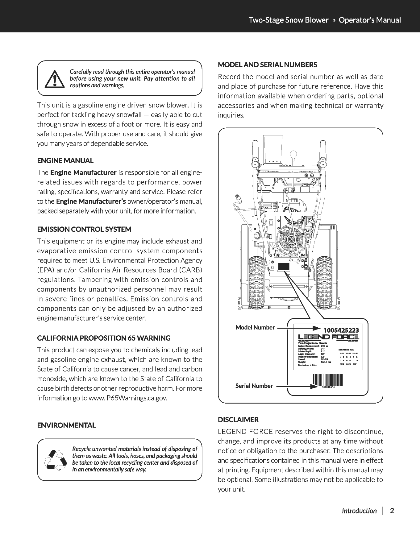
MODEL AND
SERIAL
NUMBERS
Record
the
model and serial
number
as
well
as
date
and place
of
purchase
for
future
reference. Have this
information
available when
ordering
parts, optional
accessories and when making technical
or
warranty
inquiries.
Model Number
-~==•:-
1
~
0
~
0
~
5
~
4
~
25
;.
2
;:
2
~
3
~
b,.=§.G:NDF~
......,..
__
En!&lnel*placement:
208cc
a-IIIJ
Width:
24"
lnt.ke~pth:
21"
Aqii'DIImeter:
:12"
lm.-I
...
DIIIm.tw:
:12"
Speed:
6F+2R
WeiCht:
1.56.51bs
DISCLAIMER
LEGEND FORCE reserves
the
right
to
discontinue,
change, and improve its products at any time
without
notice
or
obligation
to
the purchaser. The descriptions
and
specifications contained
in
this manual were
in
effect
at printing. Equipment described within this manual
may
be
optional.
Some
illustrations
may
not
be
applicable to
your unit.
Introduction
I 2
SUPPORT
Have
questions
about
your
LEGEND FORCE
equipment? Call
us
at 1-844-927-3629.
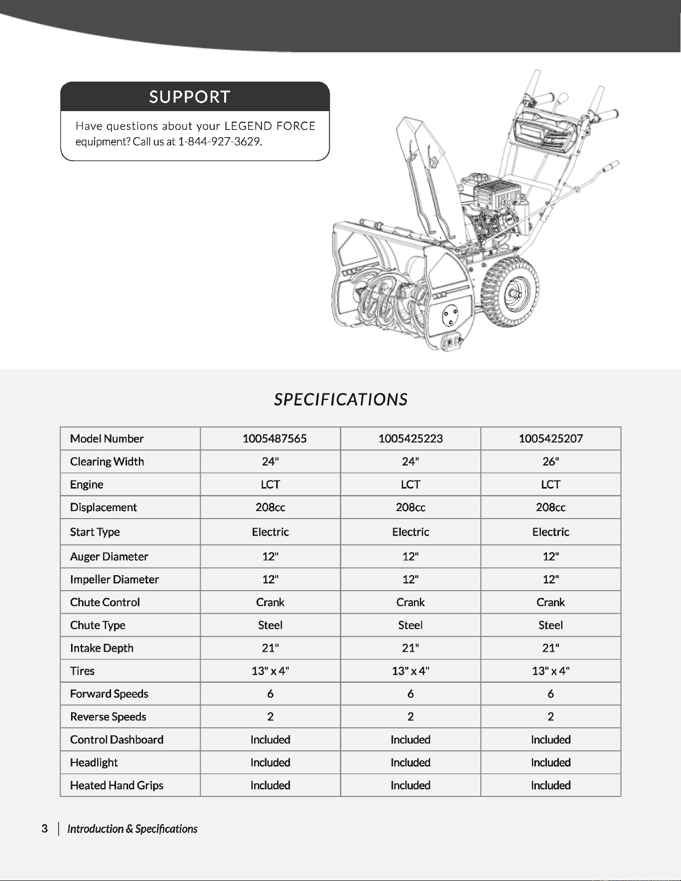
SPEC
IF
I
CAT/
0
NS
Model Number
Clearing
Width
Engine
Displacement
Start Type
Auger Diameter
Impeller Diamet
Chute Control
er
Chute Type
Intake Depth
Tires
Forward Speeds
Reverse Speeds
Control Dashboa rd
Headlight
Heated Hand Gr
ips
3 I Introduction &
Specifications
1 0054875
24"
LCT
208cc
Electric
12"
12"
Crank
Steel
21"
13"x4"
6
2
Included
Included
Included
65
10
054252
24"
LCT
208cc
Electric
12"
12"
Crank
Steel
21"
13"x4"
6
2
Included
Included
Included
23
10
054252
07
-
26"
LCT
208cc
Electric
12"
12"
Crank
Steel
21"
13"x4"
6
2
Included
Included
Included
Two-Stage
Snow
Blower » Operator's Manual
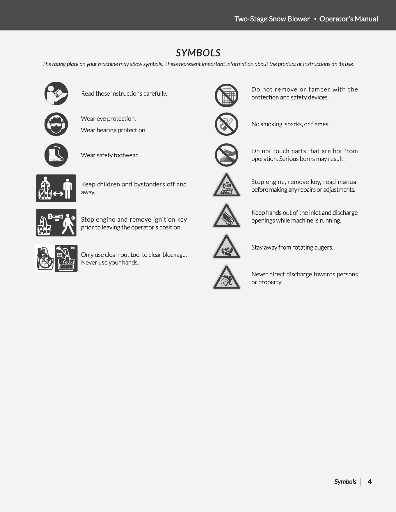
SYMBOLS
The
rating plate
on
your
machine
may
show
symbols.
These
represent
important information about
the
product
or
instructions
on
its
use.
~
e
~
Read
these instructions carefully.
Wear
eye
protection.
Wear hearing protection.
Wear safety footwear.
Keep
children
and bystanders
off
and
away.
Stop
engine
and
remove
ignition
key
prior
to
leaving the operator's position.
Only
use
clean-out tool
to
clear blockage.
Never
use
your hands.
Do
not
remove
or
tamper
with
the
protection
and
safety devices.
No smoking, sparks,
or
flames.
Do
not
touch
parts
that
are
hot
from
operation. Serious burns may result.
Stop engine, remove
key,
read manual
before making
any
repairs
or
adjustments.
Keep
hands
out
of
the inlet
and
discharge
openings while machine
is
running.
Stay away from rotating augers.
Never direct discharge towards persons
or
property.
Symbols
I 4
SAFETY
GENERAL
SAFETY
RULES
UNDERSTAND
YOUR
MACHINE
Read
this manual
and
labels affixed
to
the machine
to
understand
its limitations
and
potential hazards.
Be
thoroughly
familiar
with
the
controls
and
their
proper
operation. Know
how
to
stop
the
machine and disengage
the
controls quickly.
Make sure
to
read
and
understand all the instructions
and
safety
precautions
as
outlined in
the
Engine Manufacturer's manual
packed separately
with
your unit. Do not attempt
to
operate the
machine until you fully understand how
to
properly operate
and
maintain the engine
and
how
to
avoid accidental injuries and/or
property
damage.
If
the unit
is
to
be
used
by someone other than original purchaser
or
loaned, rented,
or
sold, always provide this manual
and
any
needed safety training before operation. The user
can
prevent
and is responsible
for
accidents
or
injuries
that
may occur
to
themselves, other people,
and
property.
Do
not
force
the
machine. Use
the
correct
machine
for
your
application. The correct machine will do the job more efficiently
and
safer at the rate
it
was
designed.
PERSONAL
SAFETY
Do not permit children
to
operate this machine at any time.
Keep children, pets, and
other
people
not
using
the
unit
away
from the
work
area.
Be
alert
and
shut
off
unit
if
anyone enters
work
area.
Keep
children under the watchful care
of
a responsible
adult.
Do
not
operate the machine while under the influence
of
drugs,
alcohol,
or
any medication
that
could affect your ability
to
use
it
properly.
Dress properly. Wear heavy long pants, boots,
and
gloves. Do not
wear loose clothing, short pants,
or
jewelry
of
any kind. Secure
long hair
so
it
is above shoulder level. Keep your hair, clothing,
and gloves away
from
moving parts. Loose clothes, jewelry,
or
long hair
can
be
caught in moving parts.
Protect eyes, face, and head
from
objects
that
may
be
thrown
from the unit. Always wear safety goggles
or
safety
glasses
with
side shields when operating.
5 I Safety
Wear appropriate hearing protection.
Always keep hands
and
feet away from all moving parts during
operation. Moving parts
can
cut or crush body parts.
Always keep hands
and
feet away from all pinch points.
Do
not touch parts that might be hot from operation. Allow parts
to
cool
before attempting
to
maintain, adjust, or
service.
Stay alert, watch
what
you are doing, and use common sense
when operating the machine.
Do
not
overreach. Do
not
operate
the
machine while barefoot
or
when wearing sandals
or
similar lightweight footwear. Wear
protective
footwear
that
will
protect
your
feet
and improve
your
footing
on
slippery
surfaces. Keep
proper
footing
and
balance at all times. This enables better control
of
the machine in
unexpected situations.
INSPECT
YOUR
MACHINE
Check your machine before starting it.
Keep
guards in place
and
in
working
order. Make sure all nuts, bolts, etc., are securely
tightened.
Never operate the machine when
it
is
in need
of
repair
or
is in
poor mechanical condition. Replace damaged, missing,
or
failed
parts before using it. Check
for
fuel leaks. Keep the machine in
safe working condition.
Do not
use
the machine
if
the engine's switch
does
not turn
it
on
or
off. Any gasoline powered machine
that
can't
be
controlled
with
the engine switch
is
dangerous
and
must
be
replaced.
Regularly check
to
see
that
keys and adjusting wrenches are
removed from the machine area before starting it. A wrench
or
a key
that
is
left attached
to
a rotating part
of
the machine may
result in personal injury.
Avoid accidental starting.
Be
sure the engine's switch
is
off
before
transporting
the
machine
or
performing
any maintenance
or
service on the unit. Transporting
or
performing maintenance
or
service on a machine with its switch on invites accidents.
If
the
machine should
start
to
vibrate
abnormally,
stop
the
engine (motor)
and
check immediately
for
the
cause.
Vibration
is
generally a warning sign
of
trouble.
ENGINE
SAFETY
This machine is equipped
with
an
internal combustion engine.
Do not
use
on
or
near any unimproved, forest covered,
or
brush
covered land unless the exhaust system
is
equipped
with
a spark
arrester meeting applicable local, state,
or
federal laws.
In
the
state
of
California, a spark
arrester
is required by law.
Other
states have similar laws. A spark arrester,
if
used,
must
be
maintained in effective working order by the operator.
Never
start
or
run the engine inside a closed area. The exhaust
fumes are dangerous, containing carbon monoxide,
an
odorless
and
deadly
gas.
Operate
this
unit
only
in a
well-ventilated
outdoor area.
Do
not
tamper
with
the engine
to
run
it
at
excessive
speeds.
The
maximum engine speed is preset by
the
manufacturer
and is
within safety limits.
See
engine manual.
Keep a Class B
fire
extinguisher on hand when operating
this
snow blower in
dry
areas
as
a precautionary measure.
FUEL
SAFETY
Fuel
is
highly flammable, and
its
vapors can explode
if
ignited.
Take
precautions when using
to
reduce
the
chance
of
serious
personal injury.
When
refilling
or
draining
the
fuel tank, use
an
approved fuel
storage container while in a clean, well-ventilated outdoor area.
Do
not
smoke,
or
allow sparks, open flames,
or
other
sources
of
ignition near
the
area
while
adding fuel
or
operating
the
unit.
Never fill the fuel tank indoors.
Two-Stage Snow Blower » Operator's Manual
Keep grounded conductive objects, such
as
tools, away
from
exposed, live electrical parts
and
connections
to
avoid sparking
or
arcing. These events could ignite fumes
or
vapors.
Always stop the engine
and
allow
it
to
cool before filling the fuel
tank. Never remove the cap
of
the fuel tank
or
add
fuel while the
engine
is
running
or
when the engine
is
hot. Do not operate the
machine
with
known leaks in the fuel system.
Loosen
the fuel tank
cap
slowly
to
relieve any pressure in the tank.
Never overfill
the
fuel tank. Fill the
tank
to
no more than
1/2"
below the bottom
of
the filler neck
to
provide space
for
expansion
as
the heat
of
the engine
can
cause
fuel
to
expand.
Replace
all
fuel tank
and
container
caps
securely
and
wipe up spilled
fuel. Never operate the unit without the fuel
cap
securely in
place.
Avoid creating a source
of
ignition
for
spilled fuel.
If
fuel
is
spilled,
do
not
attempt
to
start
the engine
but
move the machine away
from the area
of
spillage
and
avoid creating any source
of
ignition
until fuel vapors have dissipated.
When fuel
is
spilled on yourself
or
your clothes, wash
your
skin
and
change clothes immediately.
Store fuel in containers specifically designed and approved
for
this purpose.
Store fuel in a cool, well-ventilated area, safely away from sparks,
open flames,
or
other
sources
of
ignition.
Never
store
fuel
or
a machine
with
fuel
in
the
tank
inside a
building where fumes may reach a spark, open flame,
or
any
other
source
of
ignition, such
as
a
water
heater, furnace,
or
clothes
dryer. Allow the engine
to
cool before storing in any enclosure.
SPECIFIC
SAFETY
RULES
Do not operate
without
wearing adequate
winter
outer garments.
Do not
use
the machine
on
a roof.
Do
not
run the engine indoors, except when starting the engine
and
for
transporting the snow
thrower
in
or
out
of
the building.
Open
the outside doors; exhaust fumes are dangerous.
Always check overhead and side clearances
carefully
before
operation.
Always
be
aware
of
traffic
when
operating
along
streets
or
curbs.
Thoroughly inspect the area
to
be
worked. Keep the working area
clean
and
free
of
toys, doormats, newspapers, sleds, boards, wires
and
other
foreign objects, which could
be
tripped over
or
thrown
by the auger/impeller. Check
for
weak spots on docks, ramps
or
floors.
Plan
your
snow-throwing
pattern
to
avoid discharge
toward
people
or
areas where property damage
can
occur.
Do
not
operate
near
drop-offs,
ditches,
or
embankments.
Machine
can
suddenly
turn
over
if
a wheel
is
over the edge
of
a
cliff
or
ditch,
or
if
an
edge
caves
in.
Keep all bystanders, children, and pets
at
least 75
feet
(23m)
away.
If
you are approached, stop the
unit
immediately.
Use
a grounded three-wire extension cord
and
receptacle
for
all
machines
with
electric start engines.
Safety I 6
Check clutch
and
brake operation frequently. Adjust and service
as
required. All motion
of
drive wheels
and
auger/impeller must
stop quickly when control levers are released.
Let engine and machine adjust
to
outdoor
temperature before
starting
to
clear snow.
Stay alert
for
hidden hazards
or
traffic.
Do
not
overload machine capacity by attempting
to
clear snow at
too fast
of
a rate.
Do not
throw
snow any higher than necessary.
Adjust
auger housing
height
to
clear gravel
or
crushed
rock
surfaces. Exercise extreme caution when operating.
Exercise caution
to
avoid slipping
or
falling, especially
when
operating in reverse. Never operate machine
at
high
transport
speeds on slippery surfaces. Always look down
and
behind before
and while backing.
Do
not
operate on steep slopes. Do
not
clear snow across
the
face
of
slopes.
Keep
all movement on slopes slow and gradual. Do
not make sudden changes in speed
or
direction.
Use
a slow speed
to
avoid stops
or
shifts
on slopes. Avoid
starting
or
stopping
on a slope. Do
not
park machine on a slope unless absolutely
necessary. When parking on a slope, always block the wheels.
Disengage power
to
the auger/impeller when transporting
or
not
in
use.
Disengage all control levers
and
stop engine before you leave the
operating position (behind
the
handles).
Wait
until
the
auger/
impeller comes
to
a complete stop before unclogging the chute
assembly, making any adjustments,
or
inspections.
Hand
contact
with
the
rotating
impeller
inside
the
discharge
chute
is
the most common cause
of
injury
associated
with
snow
throwers. Do
not
unclog chute assembly while engine
is
running.
Shut
off
engine
and
remain behind handles until all moving parts
have stopped before unclogging. Never
put
your
hand in
the
discharge
or
collector openings. Always use the clean-out
tool
provided
to
unclog the discharge opening.
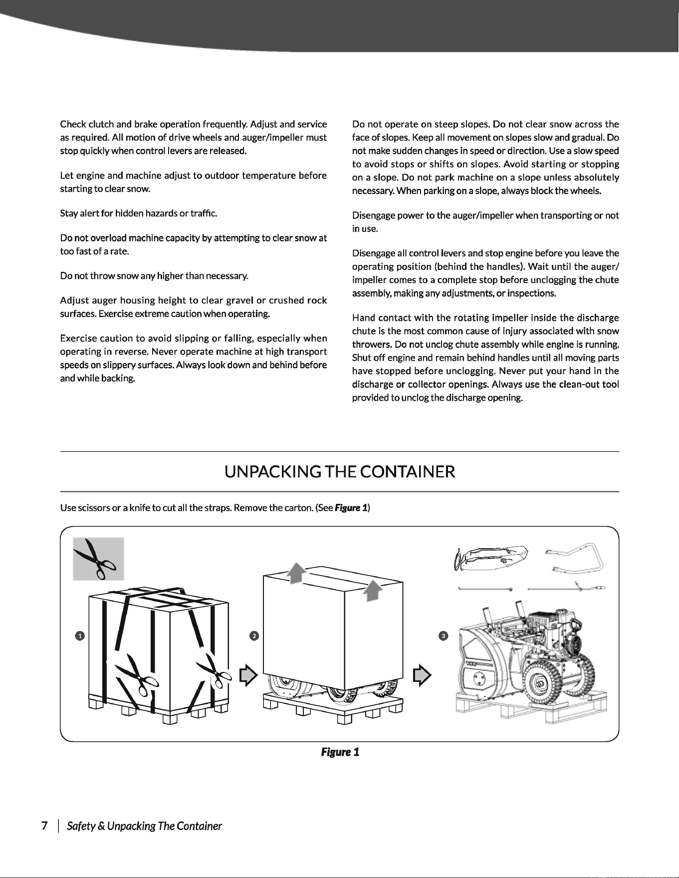
UNPACKING THE CONTAINER
Use
scissors
or
a knife
to
cut all the straps. Remove the carton.
(See
fisure 1)
e
figure1
7 I
Safety
&
Unpacking
The
Container
Two-Stage Snow Blower • Operator's Manual
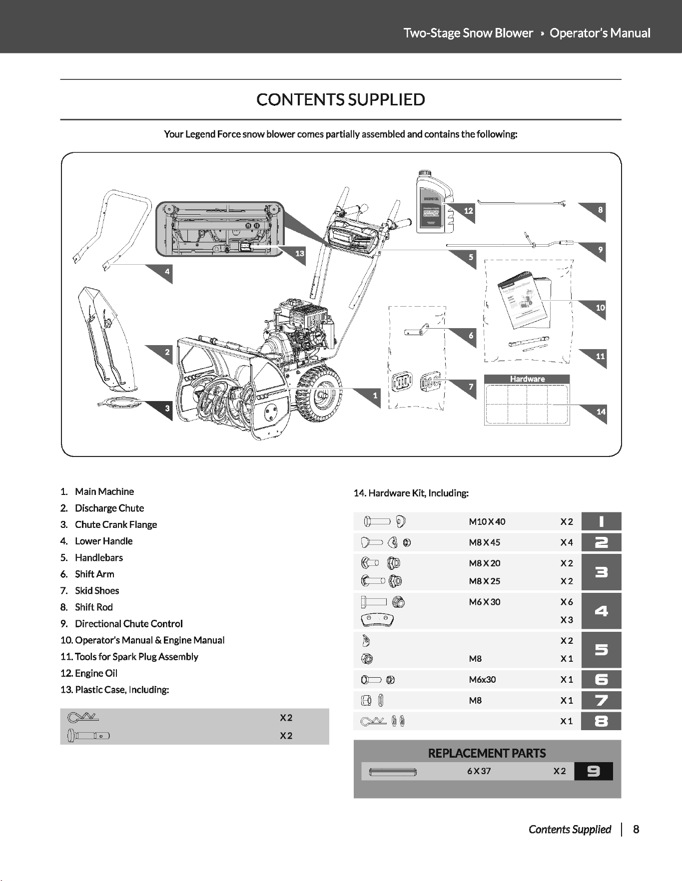
CONTENTS
SUPPLIED
Your
Legend Force
snow
blower
comes
partially
assembled and contains
the
following:
1.
Main
Machine
2.
Discharge
Chute
3.
Chute Crank
Flange
4.
Lower
Handle
5. Handlebars
6.
Shift
Arm
7. Skid Shoes
8.
Shift
Rod
9.
Directional
Chute
Control
10. Operator's Manual & Engine Manual
11. Tools
for
Spark Plug Assembly
12. Engine
Oil
13. Plastic Case, Including:
~
X2
(l)n
[)
0 )
X2
r-------,
I
~·
, '1
rd~-"'<1-·
I
1\
I I
__
....
1!
//
I
I
I
I~
'I
I
I
1!
r'
I
~
~
_/
__
_ _
__
- _ l,
':J
I
I I
't
,
'
~
~
c-i-
~--
.
(
l!!!!!!l
r
g:;!'l~~~~
-,
1!!!!!!·
I
I
~
'
:
::
"44
I
~
----
L
___
JL
___
j
L L - - - - - _ \,) : : :
:1-
-
--c
~
:----........_,..-.-.
~
-
J
l
L_
)
~
14. Hardware Kit, Including:
©===J
~
M10X40
X2
1111
D==
(]\
®
M8X45
X4
1111
~
~
M8X20
X2
II
t=n
~
M8X25
X2
~~
M6X30
X6
II
\!:::!)
X3
~
X2
II
~
M8
Xl
OJ=>
Q}
M6x30
Xl
(8)
00
M8
Xl
~
@@
X1
REPLACEMENT
PARTS
6X37
Contents
Supplied
I 8
ASSEMBLY
This snow blower was partially assembled
at
the factory.
To
assemble
your
machine
follow
the
below instructions.
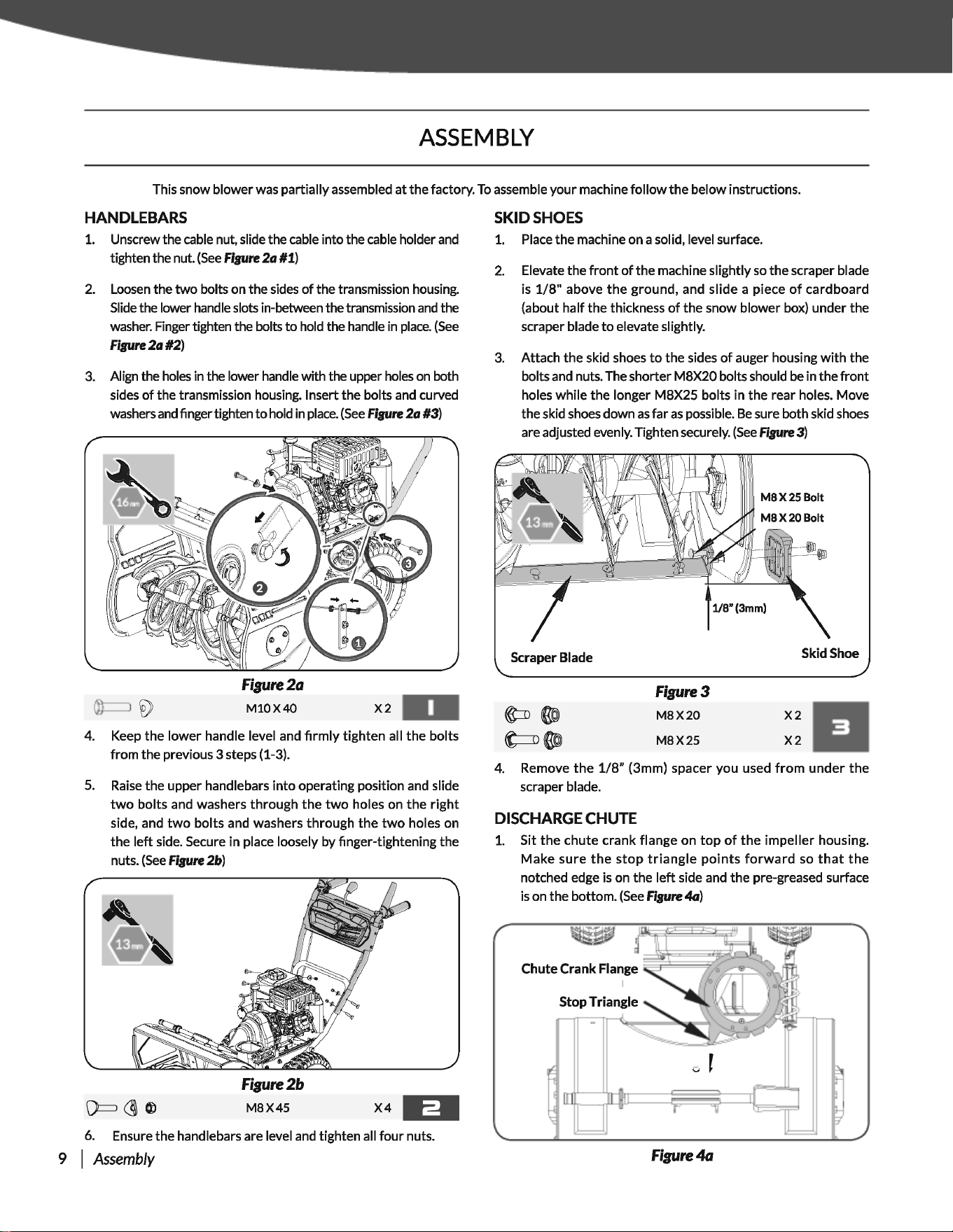
HANDLEBARS
1. Unscrew the cable nut, slide the cable into the cable holder
and
tighten the nut.
(See
Flpre
2a
#1)
2.
Loosen the
two
bolts on the sides
of
the transmission housing.
Slide the lower handle slots in-between the transmission
and
the
washer. Finger tighten the bolts
to
hold the handle in
place.
(See
Fipre
2a
#2)
3.
Align the holes in the lower handle with the upper holes on both
sides
of
the transmission housing. Insert the bolts and curved
washers
and
fmger tighten
to
hold in
place.
(See
Fipre
2a
#3)
4.
Figure2a
M10X40
X2
1111
Keep
the
lower
handle level and
firmly
tighten all
the
bolts
from
the previous 3 steps (1-3).
5.
Raise
the upper handlebars
into
operating position and slide
two
bolts and washers
through
the
two
holes on
the
right
side, and
two
bolts
and washers
through
the
two
holes on
the
left
side. Secure in place loosely by finger-tightening the
nuts.
(See
Figure
2b)
Figure2b
M8X45
X4
------
6.
Ensure
the
handlebars are level and tighten all
four
nuts.
9 I
Assembly
SKID
SHOES
1. Place
the
machine on a solid, level surface.
2.
Elevate the
front
of
the machine slightly
so
the
scraper blade
is
1/8"
above
the
ground,
and slide a piece
of
cardboard
(about half
the
thickness
of
the
snow blower box) under the
scraper blade
to
elevate slightly.
3.
Attach the skid shoes
to
the sides
of
auger housing
with
the
bolts and nuts. The shorter M8X20 bolts should
be
in the
front
holes
while
the
longer M8X25 bolts in the rear holes. Move
the skid shoes down
as
far
as
possible.
Be
sure both skid shoes
are adjusted evenly. Tighten securely.
(See
FiJure
3)
Scraper
Blade
Figure3
M8X20
M8X25
M8X25Bolt
1/8"(3mm)
Skid
Shoe
X2
11
X2
4. Remove
the
1/8"
(3mm) spacer you used
from
under
the
scraper blade.
DISCHARGE
CHUTE
1. Sit
the
chute
crank
flange on
top
of
the
impeller
housing.
Make
sure
the
stop
triangle
points
forward
so
that
the
notched edge is on the
left
side and the pre-greased surface
is on the bottom.
(See
Figure
4a)
Figure4a
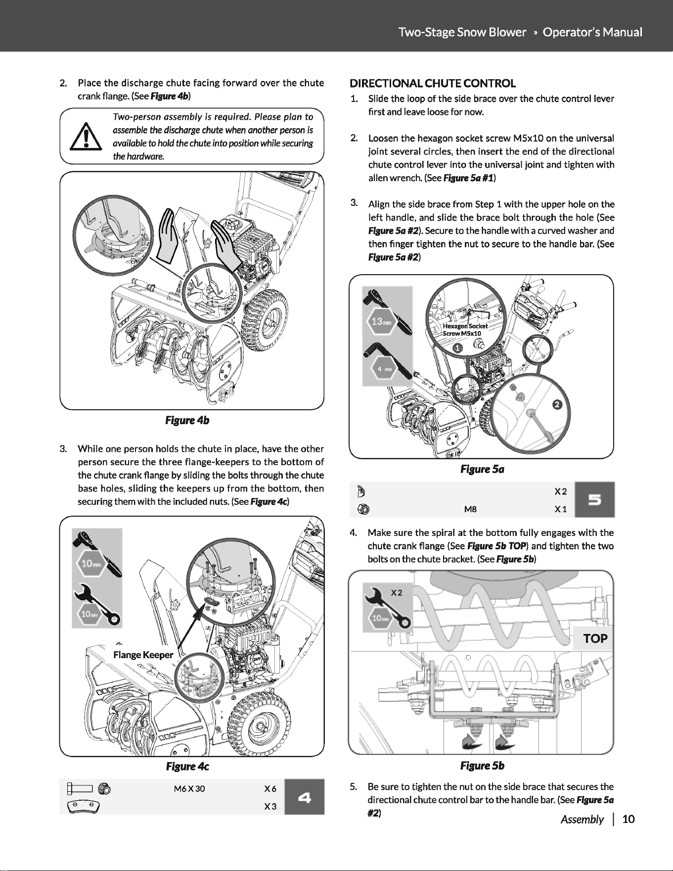
2.
Place
the
discharge chute facing
forward
over
the
chute
crank flange.
(See
Flpre
4b)
Two-person
assembly
is
required.
Please
plan
to
assemble
the
discharge
chute
when
another
person
is
available
to
hold
the
chute
into
position
while
securing
the
hardware.
Figure4b
3.
While one person holds
the
chute in place, have
the
other
person secure
the
three
flange-keepers
to
the
bottom
of
the chute crank flange by sliding the bolts through the chute
base
holes, sliding
the
keepers up
from
the
bottom, then
securing them with the included nuts.
(See
Fipre
4c)
Figure4c
X6
11
X3
M6X30
Two-Stage
Snow
Blower » Operator's Manual
DIRECTIONAL
CHUTE
CONTROL
1.
Slide the loop
of
the side brace over the chute control lever
first
and
leave loose
for
now.
2.
Loosen
the
hexagon socket screw
M5x10
on
the
universal
joint
several circles, then insert
the
end
of
the directional
chute control lever into the universal
joint
and
tighten
with
allen wrench.
(See
Figure
Sa
#1)
3.
Align the side brace from Step 1
with
the upper hole on the
left
handle,
and
slide
the
brace
bolt
through the hole
(See
Fisure
Sa
#2). Secure
to
the handle
with
a curved washer
and
then finger tighten the
nut
to
secure
to
the handle
bar.
(See
Fisure
Sa
#2)
Figure
Sa
MB
X2
11
X1
4.
Make sure the spiral
at
the
bottom
fully
engages
with
the
chute crank flange
(See
Figure
Sb
TOP)
and
tighten the
two
bolts on the chute bracket.
(See
Fisure
Sb)
FigureS&
5.
Be
sure
to
tighten the nut on the side brace
that
secures the
directional chute control bar
to
the handle
bar.
(See
Flpre
Sa
#2)
Assembly
I 10
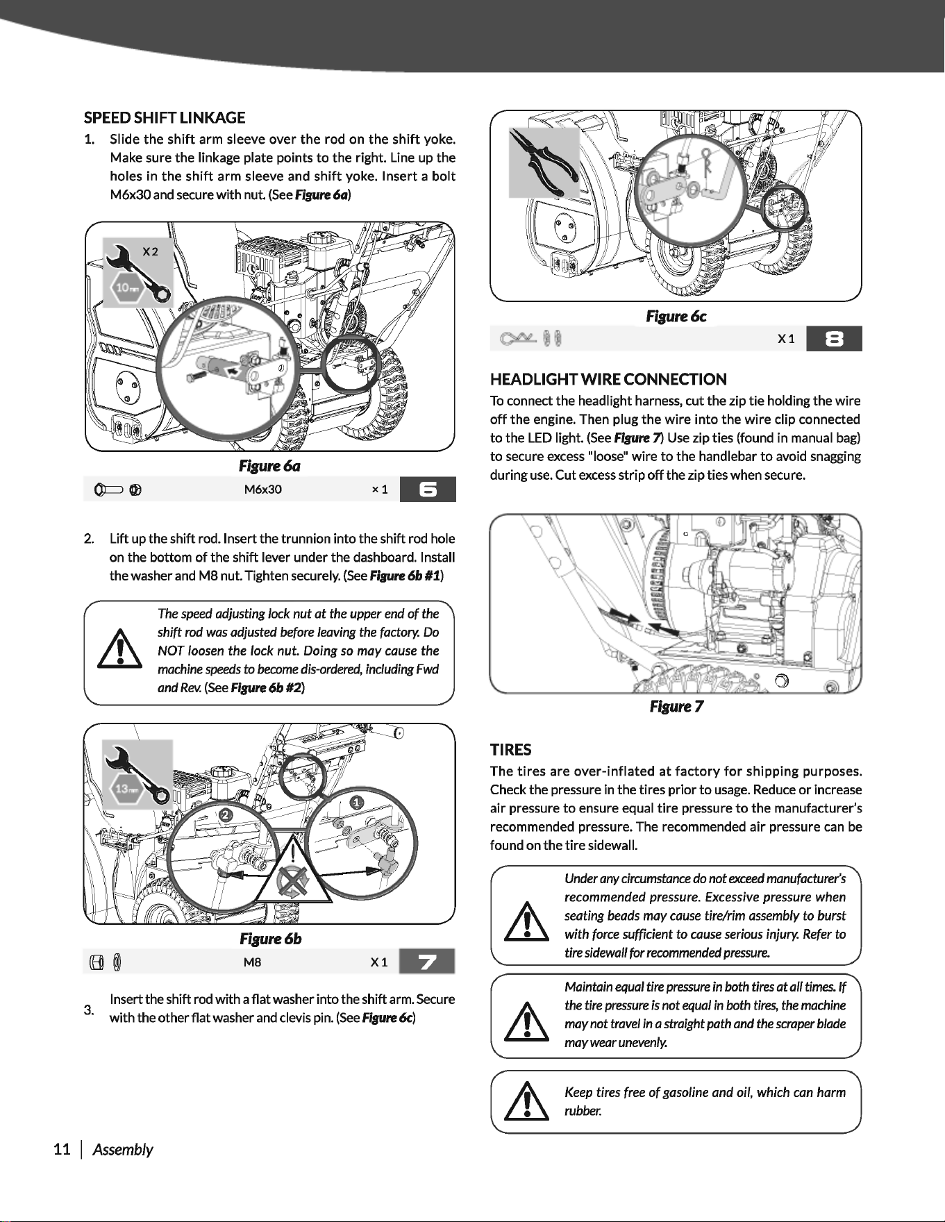
SPEED
SHIFT
LINKAGE
1.
Slide
the
shift
arm sleeve
over
the
rod on
the
shift
yoke.
Make sure
the
linkage plate points
to
the
right. Line up
the
holes in
the
shift
arm sleeve and
shift
yoke.
Insert
a
bolt
M6x30 and secure
with
nut.
(See
Fipre
6G)
Figure6a
M6x30
xl
MfM
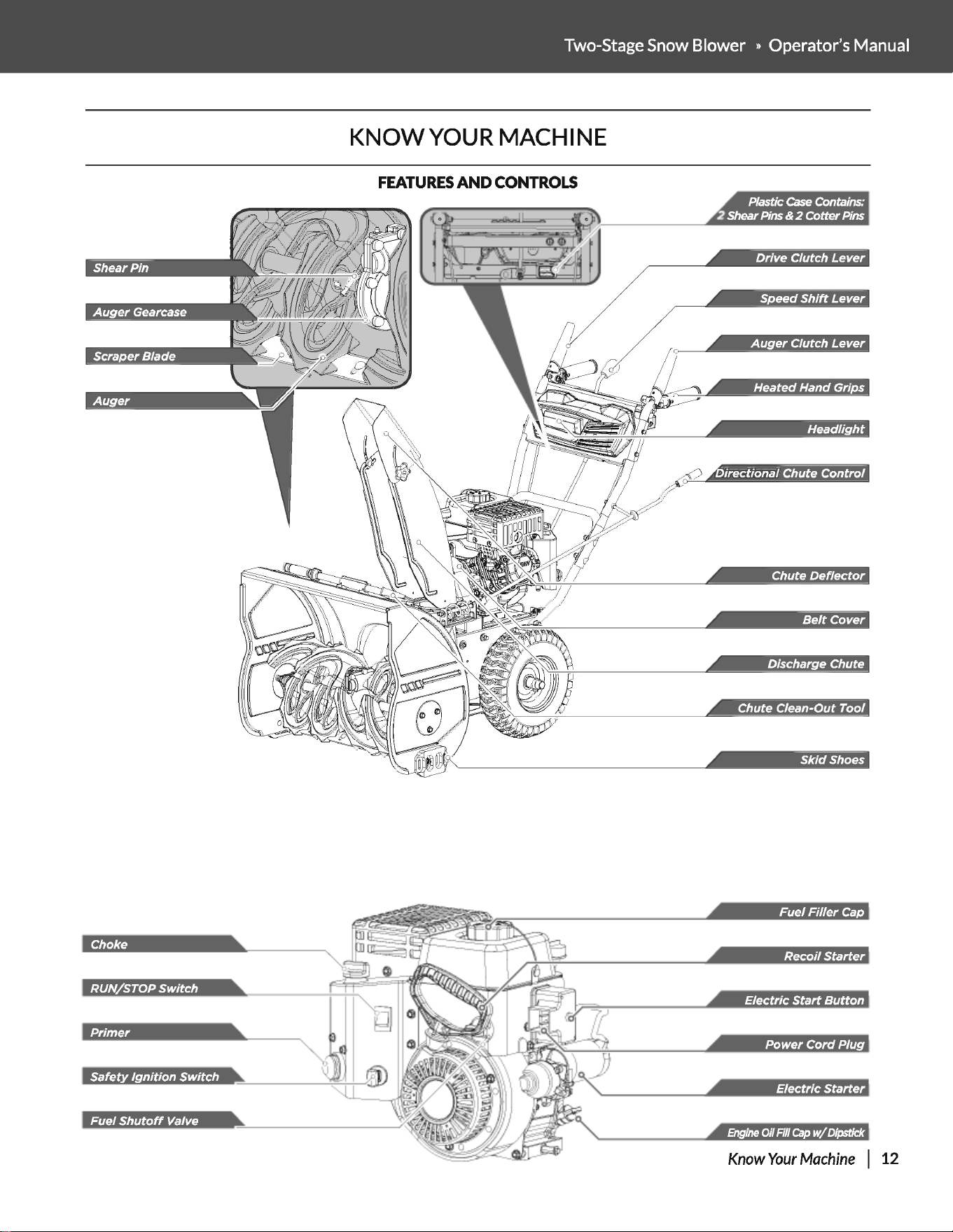
2.
Lift up the shift rod. Insert the trunnion
into
the shift rod hole
on the bottom
of
the shift lever under the dashboard. Install
the washer
and
M8
nut. Tighten securely.
(See
Fipre 6b #1)
The
speed
adjusting lock nut
at
the upper
end
of
the
shift
rod
was
adjusted
before
leaving
the
factory.
Do
NOT
loosen
the lock nut. Doing
so
may
cause
the
machine
speeds
to
become
dis-ordered,
including
Fwd
and
Rev.
(See
fipre
6b #2)
Figure6b
M8
Xl
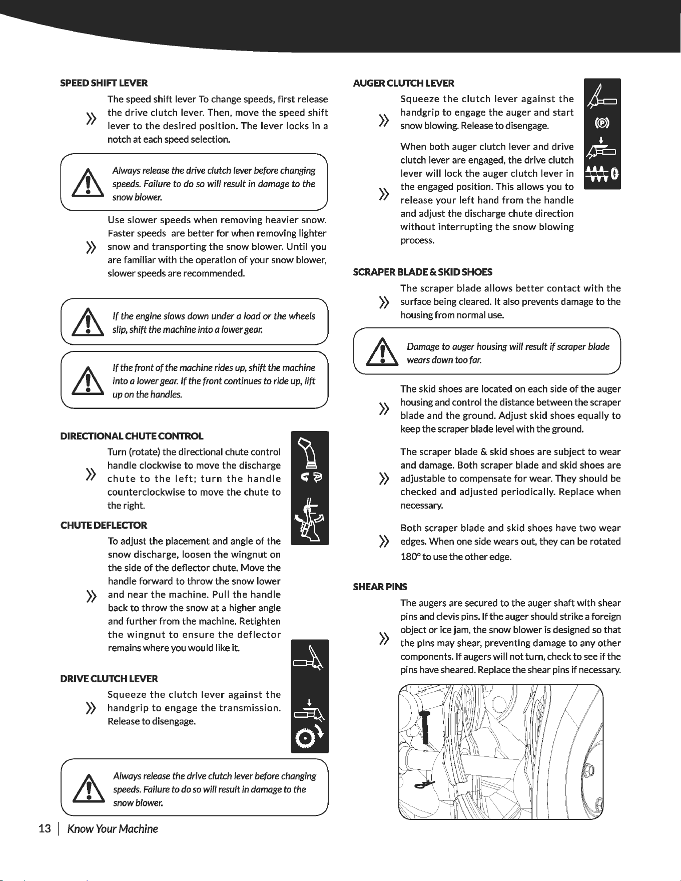
Insert the shift rod
with
a
flat
washer into the shift arm. Secure
3
·
with
the other
flat
washer
and
clevis pin.
(See
fipre
6c)
11 I
Assembly
Figure6c
Xl
•=•
HEADLIGHT WIRE CONNECTION
To
connect the headlight harness, cut the zip
tie
holding the
wire
off
the
engine. Then plug
the
wire
into
the
wire
clip connected
to
the
LED
light.
(See
Figure
7)
Use
zip ties (found in manual
bag)
to
secure
excess
"loose"
wire
to
the handlebar
to
avoid snagging
during
use.
Cut
excess
strip
off
the zip ties when secure.
Figure7
TIRES
The
tires
are
over-inflated
at
factory
for
shipping
purposes.
Check the pressure in the tires
prior
to
usage.
Reduce
or
increase
air
pressure
to
ensure equal
tire
pressure
to
the
manufacturer's
recommended pressure. The recommended
air
pressure
can
be
found on
the
tire
sidewall.
Under
any
circumstance
do
not
exceed
manufacturer's
recommended pressure.
Excessive
pressure when
seating
beads
may
cause
tire/rim
assembly
to burst
with
force
sufficient to
cause
serious
injury.
Refer
to
tire sidewall for
recommended
pressure.
Maintain
equal
tire
pressure
in
both
tires
at
all
times.
If
the
tire
pressure
is
not
equal
in
both
tires,
the
machine
may not travel
in
a straight path
and
the
scraper
blade
may
wear
unevenly.
Keep
tires
free
of
gasoline and oil, which
can
harm
rubber.
Two-Stage Snow Blower » Operator's Manual
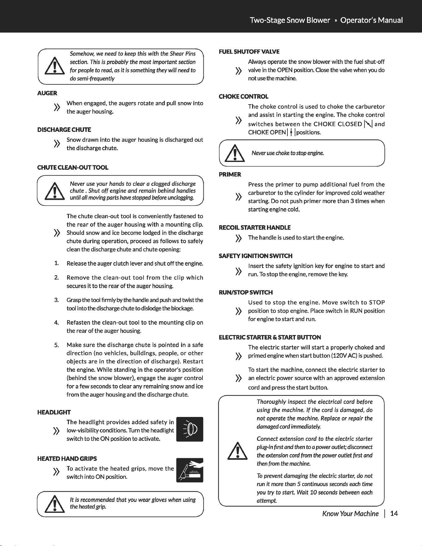
KNOW
YOUR MACHINE
FEATURES
AND
CONTROLS
=
NH§IWt!tJJ!§@i
Headlight
Chute
Deflector
Belt
Cover
Discharge Chute
Chute Clean-Out
Tool
Choke
Recoil
Starter
Primer
Power
Cord
Plug
Safety
Ignition
Switch
Fuel
Shutoff
Valve
Know
Your
Machine
I 12
SPEED
SHIFT
LEVER
The speed shift lever
To
change speeds,
first
release
))
the
drive
clutch lever. Then, move
the
speed
shift
lever
to
the
desired position. The lever locks in a
notch at
each
speed
selection.
Always
release
the
drive clutch
lever
before
changing
speeds.
Failure
to
do
so
will result
in
damage
to
the
snowblower.
Use
slower
speeds when removing heavier snow.
Faster speeds are better
for
when removing lighter
))
snow and transporting
the
snow blower.
Until
you
are familiar
with
the operation
of
your snow blower,
slower speeds are recommended.
If
the
engine
slows
down
under a
load
or
the
wheels
slip,
shift
the
machine
into
a lower
gear.
If
the
front
of
the
machine
rides
up,
shift
the
machine
into
a lower
gear.
If
the
front continues
to
ride
up,
lift
up
on
the
handles.
DIRECTIONAL
CHUTE
CONTROL
»
Turn (rotate) the directional chute control
handle clockwise
to
move
the
discharge
chute
to
the
left;
turn
the
handle
counterclockwise
to
move
the
chute
to
the right.
CHUTE
DEFLECTOR
To
adjust the placement
and
angle
of
the
snow discharge, loosen
the
wingnut
on
the side
of
the deflector chute. Move the
handle forward
to
throw
the snow lower
))
and near
the
machine. Pull
the
handle
back
to
throw
the snow at a higher angle
and
further
from the machine. Retighten
the
wingnut
to
ensure
the
deflector
remains where you would like it.
DRIVE
CLUTCH
LEVER
Squeeze
the
clutch
lever
against
the
))
handgrip
to
engage
the
transmission.
Release
to
disengage.
Always
release
the
drive clutch
lever
before
changing
speeds.
Failure
to
do
so
will result
in
damage
to
the
snowblower.
13 I
Know
Your
Machine
AUGER
CLUTCH
LEVER
»
»
Squeeze
the
clutch
lever
against
the
handgrip
to
engage
the
auger and
start
snow blowing.
Release
to
disengage.
When both auger clutch lever and drive
clutch lever are engaged, the drive clutch
lever
will
lock
the
auger clutch lever in
the engaged position. This allows you
to
release
your
left
hand
from
the
handle
and
adjust the discharge chute direction
without
interrupting
the
snow blowing
process.
SCRAPER
BLADE
&SKID
SHOES
The scraper blade allows
better
contact
with
the
))
surface being cleared.
It
also prevents damage
to
the
housing from normal
use.
~
Damage
to
auger
housing
will result
if
scraper
blade
Lll
wears
down
too
far.
»
The skid shoes are located on
each
side
of
the auger
housing
and
control the distance between the scraper
blade and
the
ground. Adjust skid shoes equally
to
keep the scraper blade level
with
the ground.
The scraper blade
& skid shoes are subject
to
wear
and damage. Both scraper blade and skid shoes are
))
adjustable
to
compensate
for
wear. They should
be
checked and adjusted periodically. Replace when
necessary.
Both scraper blade and skid shoes have
two
wear
))
edges.
When one side wears out, they
can
be
rotated
180°
to
use
the other
edge.
SHEAR
PINS
The augers are secured
to
the auger shaft
with
shear
pins
and
clevis pins.
If
the auger should strike a foreign
\. \. object
or
ice jam, the snow blower
is
designed
so
that
//
the pins may shear, preventing damage
to
any
other
components.
If
augers will
not
turn, check
to
see
if
the
pins
have
sheared.
Replace
the shear pins
if
necessary.
AUGER
Somehow,
we
need
to
keep
this
with
the
Shear
Pins
section.
This
is
probably
the
most
important
section
for
people
to
read,
as
it
is
something
they
will
need
to
do
semi-frequently
))
When engaged,
the
augers rotate and pull snow
into
the auger housing.
DISCHARGE
CHUTE
))
Snow drawn
into
the auger housing
is
discharged
out
the discharge chute.
CHUTE
CLEAN-OUT
TOOL
Never
use
your
hands
to
clear
a
clogged
discharge
chute . Shut off
engine
and
remain
behind
handles
until
all
moving
parts
have
stopped
before
unclogging.
The chute clean-out
tool
is
conveniently fastened
to
the
rear
of
the
auger housing
with
a mounting clip.
))
Should snow and ice become lodged in
the
discharge
chute during operation, proceed
as
follows
to
safely
clean the discharge chute and chute opening:
1.
Release
the auger clutch lever and shut
off
the engine.
2.
Remove
the
clean-out
tool
from
the
clip
which
secures
it
to
the rear
of
the auger housing.
3.
Grasp
the tool firmly by the handle
and
push
and
twist the
tool into the discharge chute
to
dislodge the
blockage.
4. Refasten
the
clean-out
tool
to
the
mounting clip on
the rear
of
the auger housing.
5. Make sure
the
discharge chute is pointed in a safe
direction
(no vehicles, buildings, people,
or
other
objects
are in
the
direction
of
discharge).
Restart
the engine.
While
standing in
the
operator's position
(behind
the
snow blower), engage
the
auger control
for
a
few
seconds
to
clear any remaining snow and ice
from
the
auger housing and
the
discharge chute.
HEADLIGHT
The
headlight
provides added
safety
in
))
low-visibility conditions. Turn the headlight
switch
to
the ON position
to
activate.
HEATED
HAND
GRIPS
E
))
To
activate
the
heated grips, move
the
~
switch into ON position.
1-
It
is
recommended
that
you
wear
gloves
when
using
the
heated
grip.
Two-Stage Snow Blower » Operator's Manual
FUEL
SHUTOFF
VALVE
Always operate the snow blower
with
the fuel shut-off
))
valve
in
the
OPEN
position.
Close
the valve when you do
not
use
the
machine.
CHOKE
CONTROL
The choke
control
is
used
to
choke
the
carburetor
\.\. and assist in
starting
the
engine. The choke control
//
switches
between
the
CHOKE
CLOSED
l'\.1
and
CHOKE OPEN
I f I positions.
&
Never
use
choke
to
stop
engine.
PRIMER
Press
the
primer
to
pump
additional
fuel
from
the
))
carburetor
to
the cylinder
for
improved cold weather
starting. Do
not
push primer more than 3 times when
starting engine cold.
RECOIL
STARTER
HANDLE
))
The handle
is
used
to
start
the
engine.
SAFETY
IGNITION
SWITCH
\.\. Insert
the
safety ignition key
for
engine
to
start
and
//
run.
To
stop the engine, remove the
key.
RUN/STOP
SWITCH
Used
to
stop
the
engine.
Move
switch
to
STOP
))
position
to
stop engine. Place switch in
RUN
position
for
engine
to
start
and run.
ELECTRIC
STARTER
&START
BUTION
The electric
starter
will
start
a properly choked and
))
primed engine when start button (120V
AC)
is
pushed.
To
start
the
machine, connect
the
electric
starter
to
))
an
electric power source
with
an
approved extension
cord and press the
start
button.
Thoroughly
inspect the electrical
cord
before
using
the
machine.
If
the
cord
is
damaged,
do
not
operate
the
machine.
Replace
or
repair
the
damaged
cord
immediately.
Connect extension
cord
to
the electric starter
plug-in
(rrst
and
then
to
a
power
outlet;
disconnect
the
extension
cord
from
the
power
outlet
(rrst
and
then
from
the
machine.
To
prevent
damaging
the
electric
starter,
do
not
run
it
more
than
5
continuous
seconds
each
time
you
try to
start.
Wait
10
seconds
between
each
attempt.
Know
Your
Machine
I
14
ADJUSTMENT
SKID
SHOES
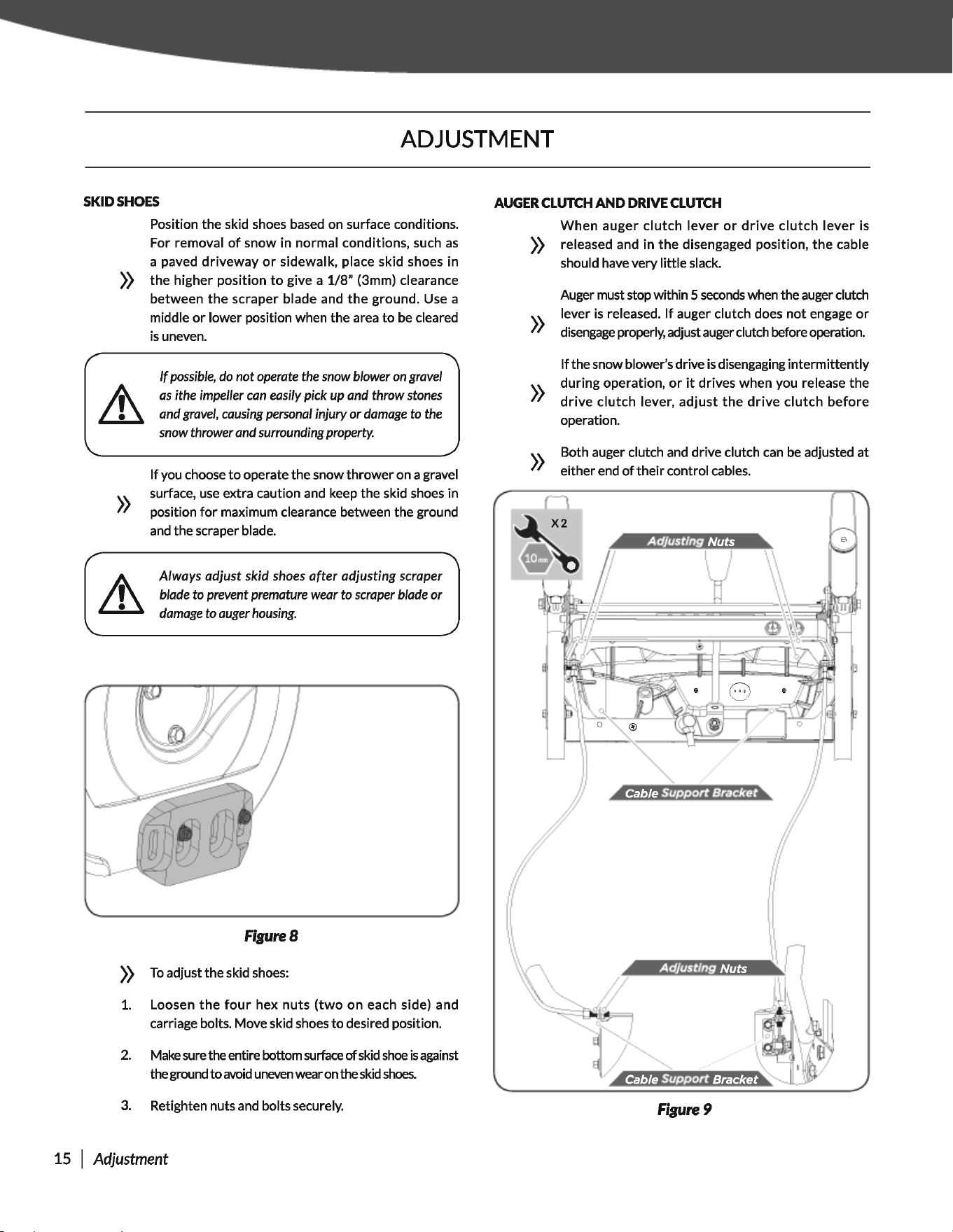
Position the skid shoes based on surface conditions.
For removal
of
snow in normal conditions, such
as
a paved
driveway
or
sidewalk, place skid shoes in
))
the
higher position
to
give a
1/8"
(3mm) clearance
between
the
scraper blade and
the
ground. Use a
middle
or
lower position when the area
to
be
cleared
is
uneven.
»
If
possible, do
not
operate the
snow
blower
on
gravel
as
ithe impeller can easily pick up and
throw
stones
and gravel, causing personal injury
or
damage
to
the
snow
thrower and surrounding property.
If
you choose
to
operate the snow
thrower
on a gravel
surface,
use
extra caution and keep the skid shoes in
position
for
maximum clearance between the ground
and
the scraper blade.
Always
adjust
skid
shoes
after
adjusting
scraper
blade
to
prevent premature wear
to
scraper blade
or
damage
to
auger housing.
FigureS
))
To
adjustthe skid shoes:
1.
Loosen
the
four
hex
nuts
(two
on each side) and
carriage bolts. Move skid shoes
to
desired position.
2.
Make
sure
the entire bottom
surface
of
skid
shoe
is
against
the ground
to
avoid
uneven
wear
on
the
skid
shoes.
3.
Retighten nuts
and
bolts securely.
15 I
Adjustment
AUGER
CLUTCH
AND DRIVE
CLUTCH
When
auger
clutch
lever
or
drive
clutch
lever
is
))
released and in
the
disengaged position,
the
cable
should have very little slack.
»
»
»
Auger must stop within 5
seconds
when the auger clutch
lever
is
released.
If
auger clutch does
not
engage
or
disengage
properly, adjust auger clutch before operation.
If
the snow blower's drive
is
disengaging intermittently
during
operation,
or
it
drives when you release the
drive
clutch
lever,
adjust
the
drive
clutch
before
operation.
Both auger clutch
and
drive clutch
can
be
adjusted
at
either end
of
their
control cables.
Figure9
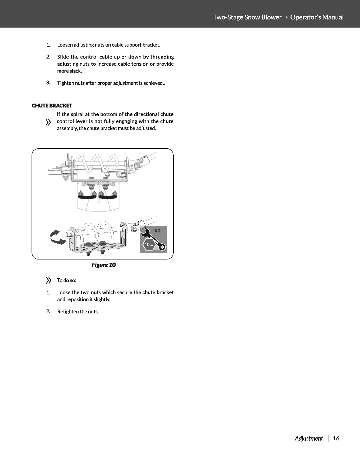
1.
Loosen
adjusting nuts on cable support bracket.
2.
Slide
the
control
cable up
or
down
by
threading
adjusting nuts
to
increase cable tension
or
provide
more slack.
3.
Tighten nuts after proper adjustment
is
achieved
..
CHUTE
BRACKET
If
the
spiral at
the
bottom
of
the
directional chute
))
control
lever is
not
fully
engaging
with
the
chute
assembly,
the chute bracket must
be
adjusted.
Figure
10
))
Todoso:
1.
Loose
the
two
nuts which secure the chute bracket
and
reposition
it
slightly.
2.
Retighten the nuts.
Two-Stage Snow Blower » Operator's Manual
Adjustment
I 16
OPERATION
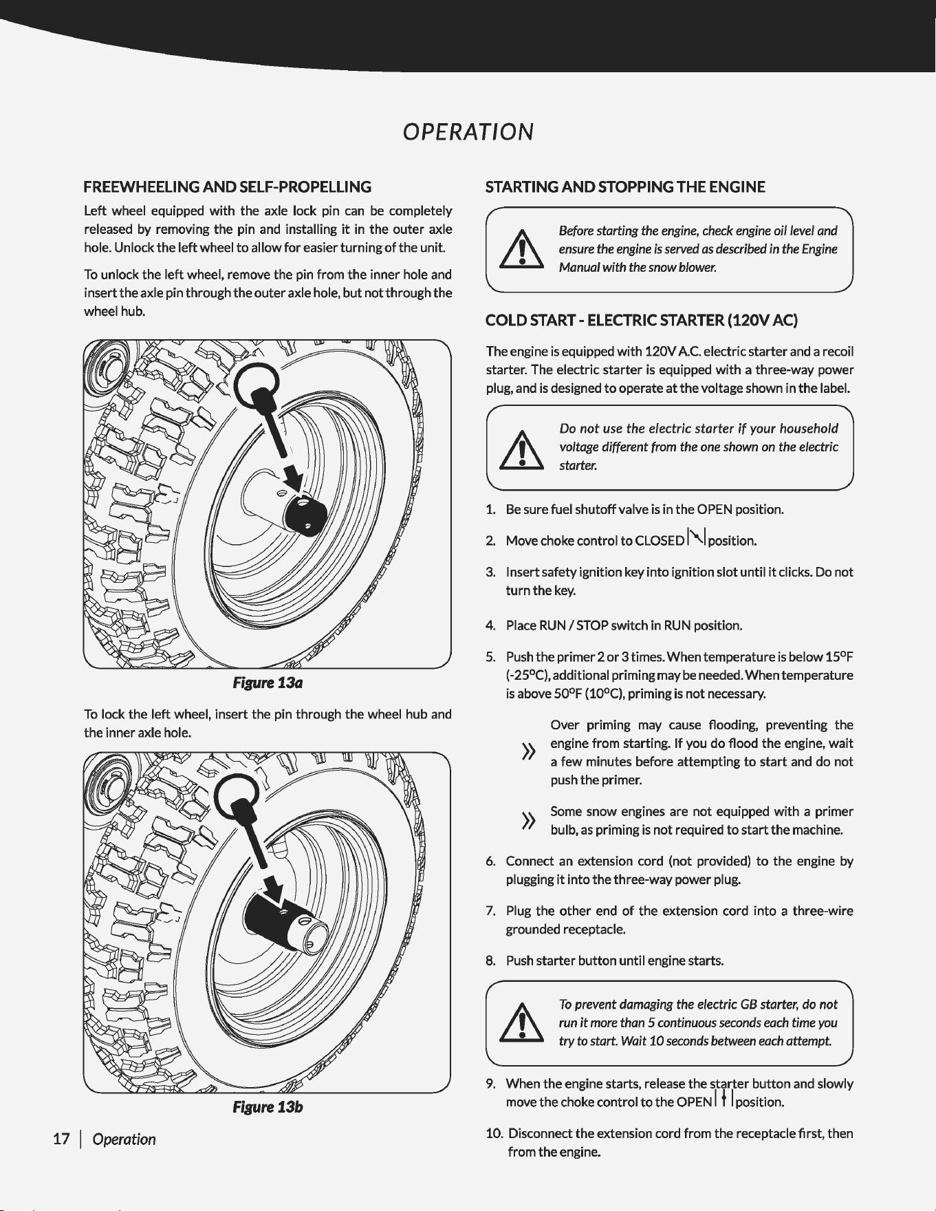
FREEWHEELING
AND
SELF-PROPELLING
Left wheel equipped
with
the axle lock pin
can
be
completely
released by removing the pin
and
installing
it
in the outer axle
hole. Unlock the
left
wheel
to
allow
for
easier turning
of
the unit.
To
unlock the
left
wheel, remove the pin from the inner hole
and
insert the axle pin through the
outer
axle hole,
but
not through the
wheel hub.
Figure
13a
To
lock the
left
wheel, insert the pin through the wheel hub
and
the inner axle hole.
Figure
13b
17 I Operation
STARTING
AND
STOPPING
THE
ENGINE
Before
starting
the
engine,
check
engine
oil
level
and
ensure
the
engine
is
served
as
described
in
the
Engine
Manual
with
the
snow
blower.
COLD
START-
ELECTRIC
STARTER
(120V
AC)
The engine
is
equipped
with
120V
A.C.
electric starter
and
a recoil
starter. The electric starter
is
equipped
with
a three-way power
plug,
and
is
designed
to
operate
at
the voltage shown in the label.
Do
not
use
the electric starter if
your
household
voltage
different
from
the
one
shown
on
the
electric
starter.
1.
Be
sure fuel shutoff valve
is
in the
OPEN
position.
2.
Move choke control
to
CLOSED
1"1
position.
3.
Insert safety ignition key into ignition slot until
it
clicks. Do not
turn
the
key.
4.
Place
RUN
I
STOP
switch in
RUN
position.
5.
Push
the primer 2
or
3 times. When temperature
is
below 15°F
(-25°C), additional priming may
be
needed. When temperature
is
above 50°F (10°C}, priming
is
not necessary.
Over priming may
cause
flooding, preventing the
))
engine from starting.
If
you do flood the engine,
wait
a
few
minutes before attempting
to
start
and
do
not
push
the primer.
))
Some
snow engines are not equipped
with
a primer
bulb,
as
priming
is
not required
to
start the machine.
6.
Connect
an
extension cord (not provided)
to
the engine by
plugging
it
into the three-way power plug.
7.
Plug the
other
end
of
the extension cord into a three-wire
grounded receptacle.
8.
Push
starter button until engine starts.
To
prevent
damaging
the
electric
GB
starter,
do
not
run
it
more
than
5
continuous
seconds
each
time
you
try
to
start.
Wait
10
seconds
between
each
attempt.
9.
When the engine starts, release the starter button
and
slowly
move the choke control
to
the OPEN I f I position.
10. Disconnect the extension cord from the receptacle first, then
from the engine.
COLD
START-
RECOIL
STARTER
1.
Be
sure fuel shutoff valve
is
in the OPEN position.
2.
Place
RUN
I
STOP
switch in
RUN
position.
3.
Rotate choke control
to
CLOSED
l"-1
position.
4.
Push
the primer 2
or
3 times. When temperature
is
below 15°F
(-25°C), additional priming may
be
needed. When temperature
is
above 50°F (10°C), priming
is
not
necessary.
»
Over priming may cause flooding, preventing the
engine from starting.
If
you do flood the engine,
wait
a
few
minutes before attempting
to
start
and do
not
push the primer.
5.
Grasp recoil starter handle and pull rope
out
slowly until
it
pulls harder. Let rope rewind slowly.
6.
Pull rope
with
a rapid continuous full arm stroke. Do
not
allow
starter rope
to
snap back.
7. Repeat steps 5 and 6 until engine starts.
8.
When the engine starts, release the recoil starter handle and
slowly move
the
choke control
to
the OPEN I f I position.
WARM
START
Follow
the
steps above, keeping the choke control in the OPEN I f I
position and do
not
use
primer.
Allow
the engine
to
warm up
for
a
few
minutes, engine
))
will
not
develop full power until
it
has
reached normal
operating temperature.
In snowy and cold conditions, some controls and
moving parts may freeze. Do
not
use
excessive force
))
when
trying
to
operate frozen controls.
If
you have
difficulty operating any control
or
part,
start
the
engine and let
is
run
for
a
few
minutes.
SNOW BLOWING
TIPS
It
is
easier and more efficient
to
remove snow immediately after
it
falls.
Two-Stage Snow Blower » Operator's Manual
The best time
to
remove snow
is
the
early morning.
At
this time
the
snow
is
usually
dry
and
has
not
been exposed
to
the
direct sun
and warming temperatures.
Slightly overlap each successive path
to
ensure all snow will
be
removed.
For large areas,
start
in the middle and
throw
snow
to
each side,
so
snow
is
not
cleared more than once.
For extremely heavy snow, reduce the
width
of
snow removal by
overlapping previous path and moving slowly.
Throw
snow downwind whenever possible.
Keep engine clean and clear
of
snow during
use.
This will help air
flow
and extend engine life.
After
snow-throwing
is
completed, let the engine run
for
a
few
minutes
to
help
dry
off
the moisture on the engine and prevent
moving parts from freezing.
Engage
the auger/impeller
to
clear
any remaining snow from inside the housing. Rotate the discharge
chute
to
prevent
it
from
freezing. Stop the engine,
wait
for
all
moving parts
to
stop, and remove all ice and snow from the snow
thrower.
With
the engine off, pull the recoil starter handle several
times
to
prevent the recoil starter from freezing up.
TRAVELING
To
travel from one
work
area
to
another:
1.
Set
throttle
to
slow
or
part-throttle
position.
2.
Press down on handle bars enough
to
raise
front
of
unit
slightly
off
surface.
3.
Engage
drive clutch
without
engaging auger clutch.
TRANSPORT
Always
shut off
engine,
remove
key,
and
dose
fuel
shut-
off
valve
when
transporting
unit
on
a
truck
or
trailer.
Do
not transport
machine
while
engine
is
running.
Use
extra care when loading
or
unloadingunitontotrailerortruck.
Secure
unit
chassis
to
transport vehicle. Never secure
from
rods
or
linkages
that
could
be
damaged.
Operation I 18
MAINTENANCE
ENGINE
Refer
to
the Engine Operator's Manual.
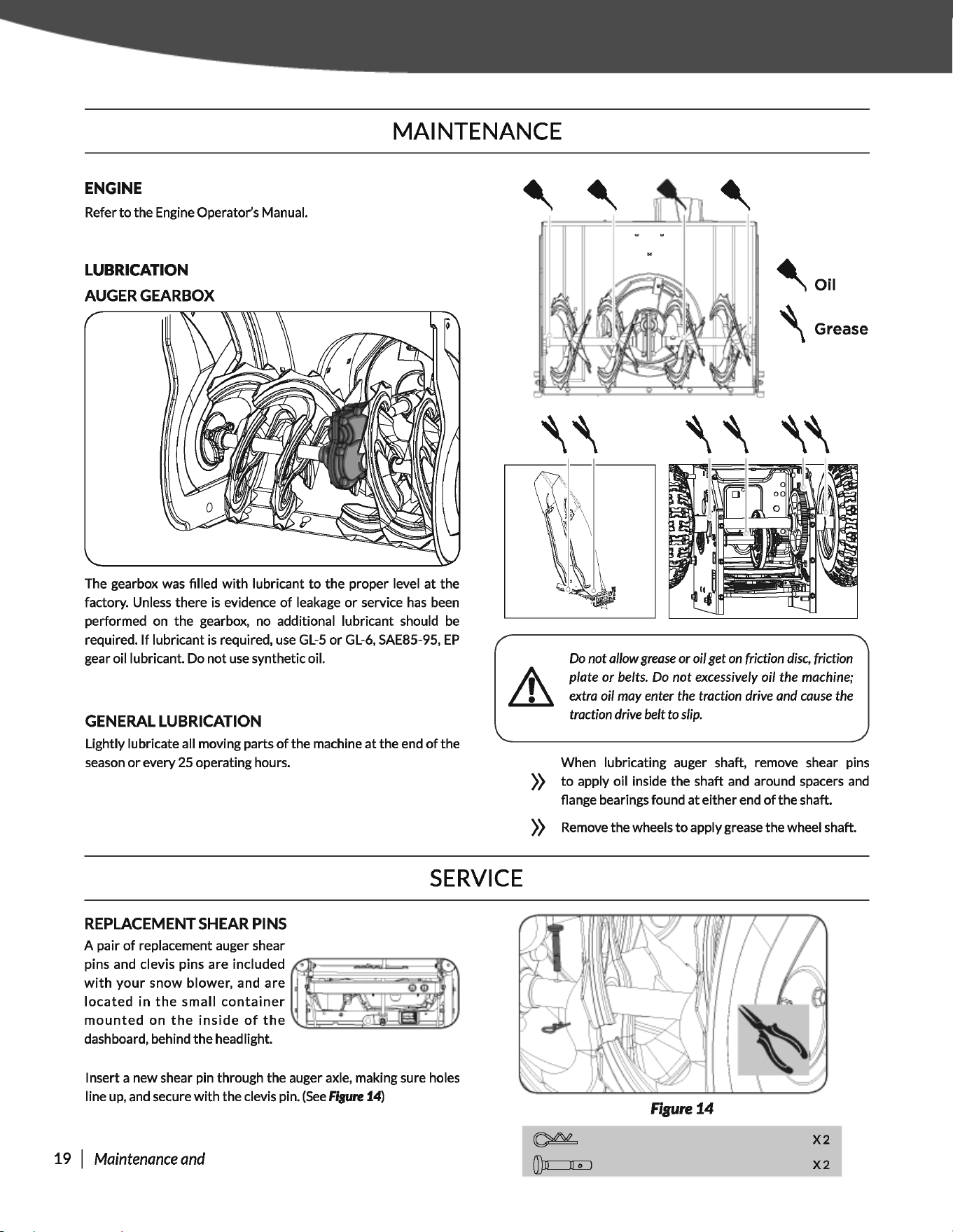
LUBRICATION
AUGER
GEARBOX
The gearbox was filled
with
lubricant
to
the proper level
at
the
factory. Unless there
is
evidence
of
leakage
or
service
has
been
performed on the gearbox, no additional lubricant should
be
required.
If
lubricant
is
required,
use
GL-5
or
GL-6,
SAE85-95,
EP
gear oil lubricant. Do not
use
synthetic oil.
GENERAL
LUBRICATION
Lightly lubricate all moving parts
of
the machine
at
the end
of
the
season
or
every 25 operating hours.
SERVICE
REPLACEMENT
SHEAR
PINS
A pair
of
replacement auger shear
pins and clevis pins are included
~~~~~~i~~~
with
your
snow
blower, and are r f
located
in
the
small
container
mounted
on
the
inside
of
the
dashboard, behind the headlight.
Insert a new shear pin through the auger axle, making sure holes
line
up,
and
secure
with
the clevis pin.
(See
fiBUre
14)
19 I
Maintenance
and
~Oil
'Grease
Do
not
allow
grease
or
oil
get
on
friction
disc,
friction
plate
or
belts.
Do
not
excessively
oil
the
machine;
extra
oil
may
enter
the
traction
drive
and
cause
the
traction
drive
belt
to
slip.
When lubricating auger shaft, remove shear pins
))
to
apply oil inside the shaft
and
around spacers
and
flange bearings found
at
either end
of
the shaft.
))
Remove the wheels
to
apply grease the wheel shaft.
Figure
14
0)11
II
o I
X2
X2
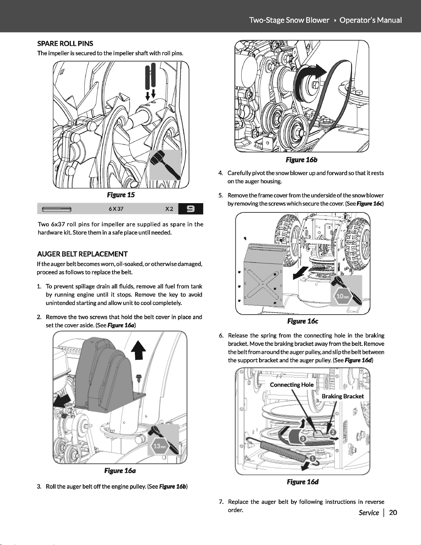
SPARE
ROLL
PINS
The impeller
is
secured
to
the impeller shaft
with
roll pins.
Figure
15
6X37
X2
-=·
Two
6x37
roll
pins
for
impeller
are supplied
as
spare
in
the
hardware kit. Store them in a safe place until needed.
AUGER
BELT
REPLACEMENT
If
the auger belt becomes worn, oil-soaked,
or
otherwise damaged,
proceed
as
follows
to
replace the belt.
1.
To
prevent spillage drain all fluids, remove all fuel from tank
by running engine until
it
stops. Remove the key
to
avoid
unintended starting and allow
unit
to
cool completely.
2.
Remove the
two
screws
that
hold
the
belt cover in place and
set the cover aside.
(See
Figure
16a)
Figure16a
3.
Roll the auger belt
off
the engine pulley.
(See
Figure
16b)
Two-Stage Snow Blower » Operator's Manual
Figure16b
4. Carefully pivot the snow blower up and forward
so
that
it
rests
on the auger housing.
5.
Remove
the frame cover from the underside
of
the snow blower
by removing the screws which secure the cover.
(See
Figure
16c)
Figure16c
6.
Release
the spring from the connecting hole in the braking
bracket. Move the braking bracket away from the belt. Remove
the belt
from
around the auger pulley, and slip
the
belt between
the support bracket and the auger pulley.
(See
Figure
16d)
Figure16d
7.
Replace the auger belt by following instructions in reverse
order.
Service
I
20
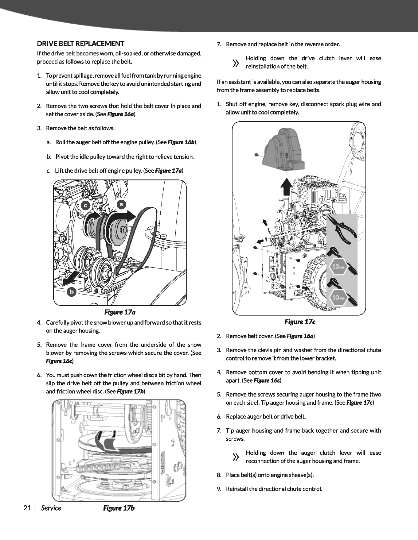
DRIVE
BELT
REPLACEMENT
If
the
drive belt becomes worn, oil-soaked,
or
otherwise damaged,
proceed
as
follows
to
replace the belt.
1.
Topreventspillage,removeallfuelfromtankbyrunningengine
until
it
stops. Remove the key
to
avoid unintended starting and
allow
unit
to
cool completely.
2.
Remove the
two
screws
that
hold
the
belt cover in place and
set the cover aside.
(See
Figure
16a)
3.
Remove
the
belt
as
follows.
a.
Roll the auger belt
off
the engine pulley.
(See
Figure
16b)
b.
Pivot the idle pulley toward the right
to
relieve tension.
c.
Lift the drive belt
off
engine pulley.
(See
Fisure
17a)
Figure
17a
4. Carefully pivot
the
snow blower up and forward
so
that
it
rests
on the auger housing.
5.
Remove the frame cover from the underside
of
the
snow
blower by removing
the
screws which secure the cover.
(See
Fisure
16c)
6.
You
must push down the friction wheel disc a
bit
by hand. Then
slip the drive belt
off
the pulley and between friction wheel
and friction wheel disc.
(See
Fisure
17b)
21 I
Service
Figure
17b
7.
Remove and replace belt in
the
reverse order.
»
Holding down the drive clutch lever will
ease
reinstallation
of
the belt.
If
an
assistant
is
available, you
can
also separate the auger housing
from
the
frame assembly
to
replace belts.
1.
Shut
off
engine, remove
key,
disconnect spark plug
wire
and
allow
unit
to
cool completely.
Figure17c
2.
Remove belt cover.
(See
Fisure
16a)
3.
Remove the clevis pin and washer from
the
directional chute
control
to
remove
it
from the lower bracket.
4. Remove bottom cover
to
avoid bending
it
when tipping
unit
apart.
(See
Fisure
16c)
5.
Remove the screws securing auger housing
to
the
frame (two
on each side). Tip auger housing and frame.
(See
Fisure
17c)
6.
Replace auger belt
or
drive belt.
7.
Tip auger housing and frame back together and secure
with
screws.
))
Holding down the auger clutch lever will
ease
reconnection
of
the auger housing and frame.
8.
Place
belt(s)
onto
engine sheave(s).
9.
Reinstall the directional chute control.
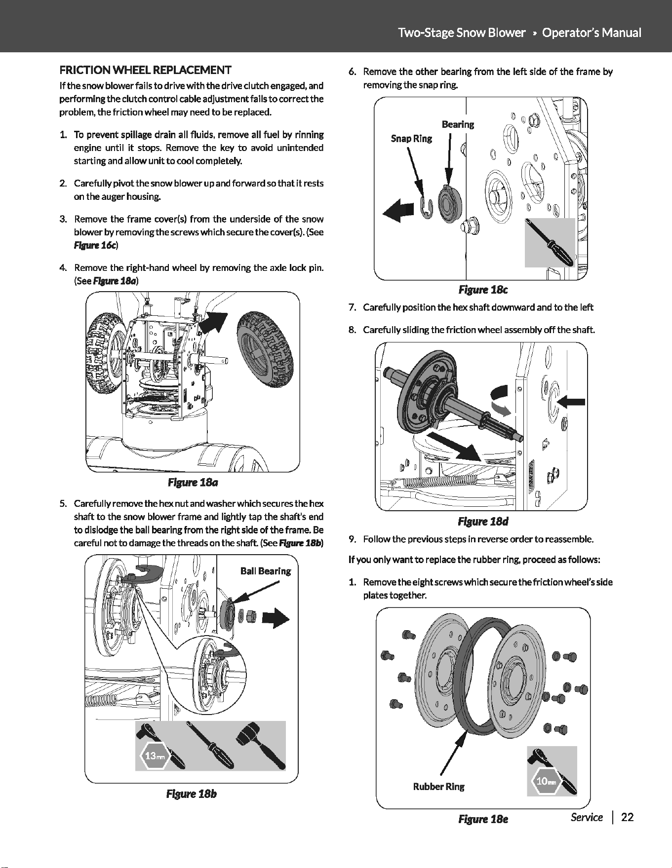
FRICTION WHEEL
REPLACEMENT
If
the
snow
blower
fails
to
drive
with
the drive clutch engaged, and
performing
the
clutch control cable adjustment fails
to
correct
the
problem,
the
friction
wheel may need
to
be replaced.
1.
To
prevent spillage drain all fluids, remove all fuel
by
rinning
engine
until
it
stops. Remove
the
key
to
avoid unintended
starting
and allow
unit
to
cool completely.
2. Carefully
pivot
the
snow
blower
up and
forward
so
that
it
rests
on
the
auger housing.
3. Remove
the
frame cover(s)
from
the
underside
of
the
snow
blower
by removi
ngthe
screws
which
secure
the
cover(s).
(See
flsure16c)
4. Remove
the
right-hand wheel by removing
the
axle lock pin.
(See
ffsure
18G)
Fl,urei8G
5. Carefully remove
the
hex
nut
and washer which secures
the
hex
shaft
to
the
snow blower frame and lightly
tap
the shaft's end
to
dislodge
the
ball bearing
from
the
right
side of
the
frame.
Be
careful
not
to
damage the threads on the
shaft
(See
fJaure
18b)
flsure
1.8b
Two-Stage Snow Blower » Operator's Manual
6. Remove
the
other
bearing
from
the
left
side
of
the
frame by
removing
the
snap ring.
Bearing
f"rgureiBc
7. Carefully position
the
hex
shaft
downward and
to
the
left
8. Carefully sliding the
friction
wheel assembly
off
the
shaft.
flsure
1.8d
9. Follow
the
previous steps
in
reverse
order
to
reassemble.
If
you
only
wantto
replace
the
rubber ring, proceed
as
follows:
1. Remove
the
eight screws which secure
the
friction
wheel's side
plates
together
.
•
•
Rubber
Ring
figure
1.8e
.
..
...
..
Service I
22
2.
Remove the rubber ring from between the plates.
3.
Reassemble the side plates
with
a new rubber ring.
When reassembling the friction wheel assembly, make
sure
that
rubber ring
is
centered
and
seated properly
between the side plates. Tighten
each
screw only
))
one rotation before turning the wheel clockwise and
proceeding
with
the next screw on the
other
side
of
the wheel. Repeat this process several times
to
ensure
the plates are secured
with
equal force between
90N.m(6 ft-lbs)
and
130N.m(9 ft-lbs).
4. Slide the friction wheel assembly back onto the hex shaft. Make
sure the shift lever pin
is
in place in the bearing housing. Follow
the steps above in reverse order
to
reassemble components.
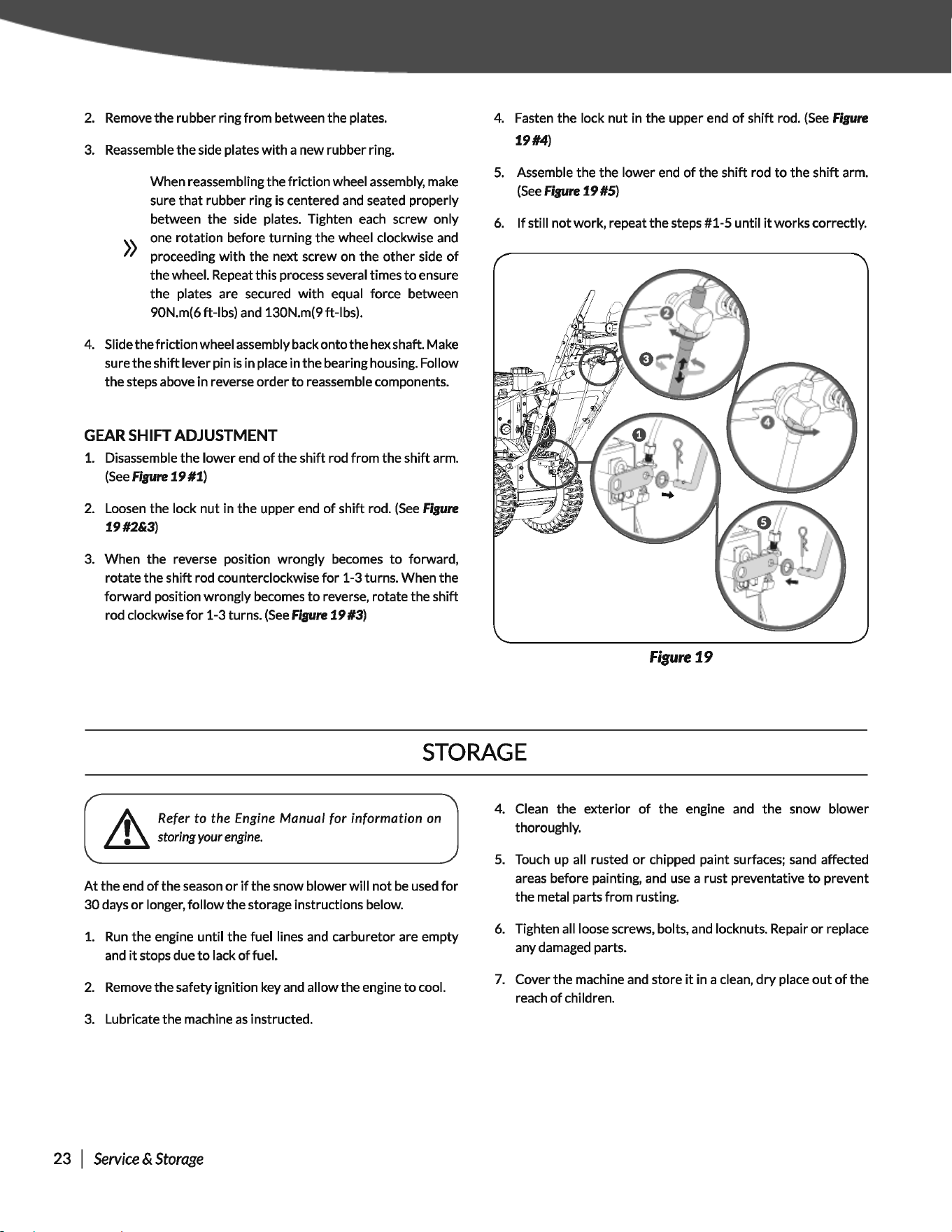
GEARSHIFT ADJUSTMENT
1.
Disassemble the lower end
of
the shift rod from the shift arm.
(See
Figure
19 #1)
2.
Loosen
the lock nut in the upper end
of
shift rod.
(See
Figure
19#2&3)
3.
When the reverse position wrongly becomes
to
forward,
rotate the shift rod counterclockwise
for
1-3 turns. When the
forward position wrongly becomes
to
reverse, rotate the shift
rod clockwise
for
1-3 turns.
(See
Figure
19 #3)
4. Fasten the lock nut in the upper end
of
shift rod.
(See
Figure
19#4)
5.
Assemble the the lower end
of
the shift rod
to
the shift arm.
(See
Figure
19 #5)
6.
If
still not work, repeat the steps #1-5 until
it
works correctly.
Figure
19
STORAGE
~
Ret~r
to the
E~gine
Manual
tor
information
on
~
stormgyour
engme.
At
the end
of
the season
or
if
the snow blower will
not
be
used
for
30
days
or
longer, follow the storage instructions below.
1.
Run
the engine until the fuel lines
and
carburetor are empty
and
it
stops due
to
lack
of
fuel.
2.
Remove the safety ignition key
and
allow the engine
to
cool.
3.
Lubricate the machine
as
instructed.
23 I
Service
&
Storage
4. Clean the exterior
of
the engine
and
the snow blower
thoroughly.
5.
Touch up all rusted
or
chipped paint surfaces;
sand
affected
areas before painting,
and
use
a rust preventative
to
prevent
the metal parts from rusting.
6.
Tighten all loose screws, bolts,
and
locknuts. Repair
or
replace
any damaged parts.
7.
Cover the machine
and
store
it
in a clean,
dry
place
out
of
the
reach
of
children.
Two-Stage Snow Blower » Operator's Manual
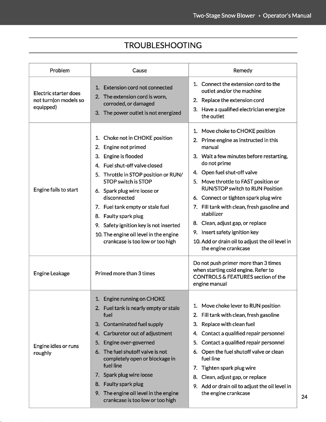
TROUBLESHOOTING
Problem Cause
Remedy
1.
Extension cord
not
connected
1.
Connect
the
extension cord
to
the
Electric
starter
does
outlet
and/or
the
machine
not
turn(on models
so
2.
The extension cord is worn,
2.
Replace
the
extension cord
corroded,
or
damaged
equipped)
3.
Have a qualified electrician energize
3.
The power
outlet
is
not
energized
the
outlet
1.
Move choke
to
CHOKE position
1.
Choke
not
in CHOKE position
2.
Prime engine
as
instructed in this
2.
Engine
not
primed
manual
3.
Engine
is
flooded
3.
Wait
a
few
minutes before restarting,
4.
Fuel
shut-off
valve closed
do
not
prime
5.
Throttle
in
STOP
position
or
RUN/
4.
Open fuel
shut-off
valve
STOP
switch
is
STOP
5.
Move
throttle
to
FAST
position
or
Engine fails
to
start
6.
Spark plug
wire
loose
or
RUN/STOP switch
to
RUN
Position
disconnected
6.
Connect
or
tighten spark plug
wire
7.
Fuel
tank
empty
or
stale fuel
7.
Fill
tank
with
clean, fresh gasoline and
8.
Faulty spark plug
stabilizer
9.
Safety ignition key is
not
inserted
8.
Clean, adjust gap,
or
replace
10. The engine oil level in
the
engine
9.
Insert safety ignition key
crankcase
is
too
low
or
too
high 10. Add
or
drain oil
to
adjust
the
oil level in
the
engine crankcase
Do
not
push
primer
more than 3 times
Engine Leakage Primed more than 3 times
when starting cold engine. Refer
to
CONTROLS &
FEATURES
section
of
the
engine manual
1.
Engine running on CHOKE
2.
Fuel
tank
is nearly
empty
or
stale
1.
Move choke lever
to
RUN
position
fuel
2.
Fill
tank
with
clean, fresh gasoline
3.
Contaminated fuel supply
3.
Replace
with
clean fuel
4.
Carburetor
out
of
adjustment
4.
Contact a qualified repair personnel
Engine idles
or
runs
5.
Engine over-governed
5.
Contact a qualified repair personnel
roughly
6.
The fuel
shutoff
valve
is
not
6.
Open
the
fuel
shutoff
valve
or
clean
completely open
or
blockage in fuel line
fuel line
7.
Tighten spark plug
wire
7.
Spark plug
wire
loose
8.
Clean, adjust gap,
or
replace
8.
Faulty spark plug
9.
Add
or
drain oil
to
adjust
the
oil level in
9.
The engine oil level in
the
engine
the
engine crankcase
crankcase
is
too
low
or
too
high
24
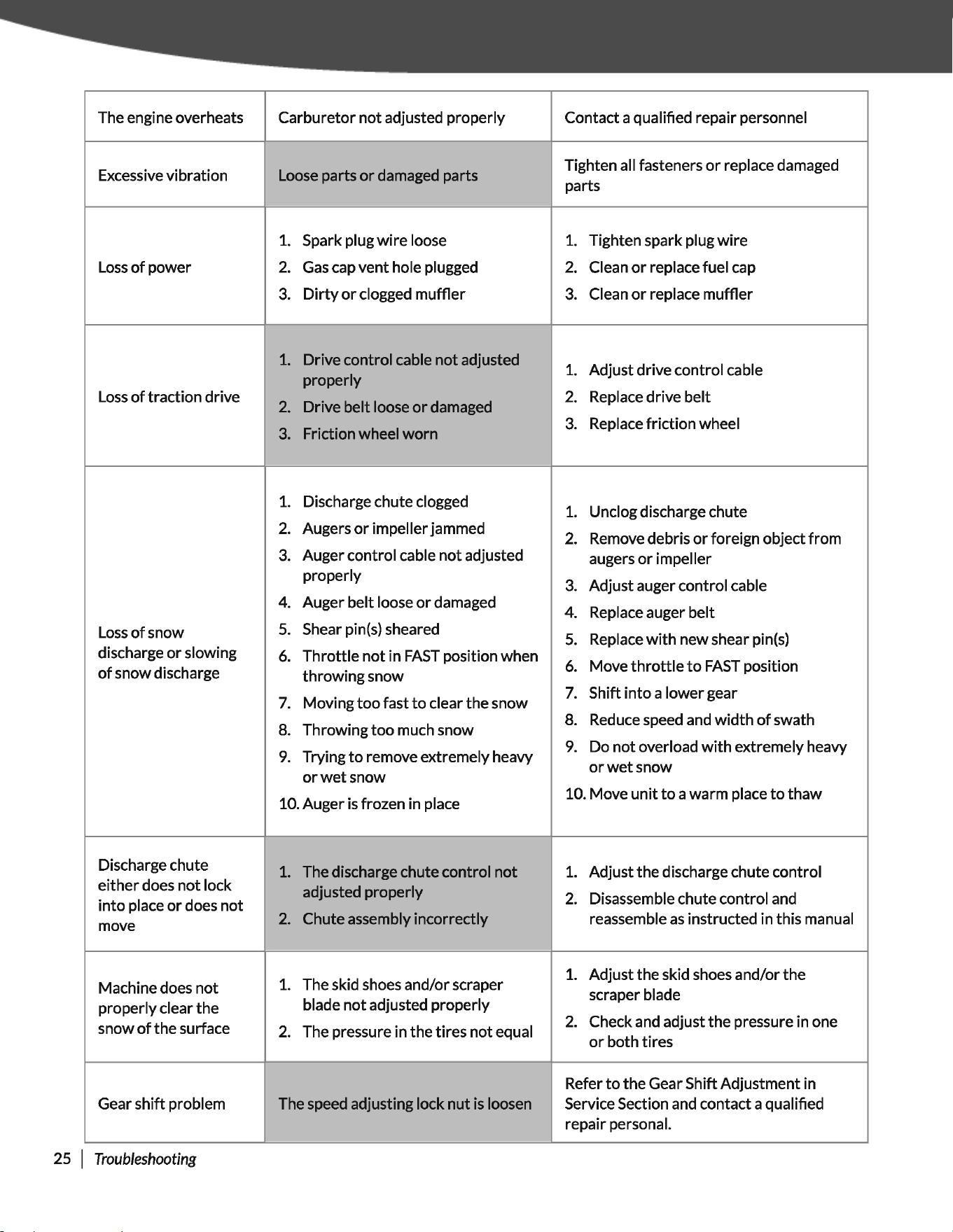
The engine overheats Carburetor
not
adjusted properly Contact a qualified repair personnel
Excessive vibration
Loose parts
or
damaged parts
Tighten all fasteners
or
replace damaged
parts
1.
Spark plug
wire
loose
1.
Tighten spark plug
wire
Loss
of
power
2.
Gas
cap
vent
hole plugged
2.
Clean
or
replace fuel cap
3.
Dirty
or
clogged
muffler
3.
Clean
or
replace muffler
1.
Drive control cable
not
adjusted
1.
Adjust drive control cable
properly
Loss
of
traction drive
2.
Drive belt loose
or
damaged
2.
Replace drive belt
3.
Friction wheel
worn
3.
Replace
friction
wheel
1.
Discharge chute clogged
1.
Unclog discharge chute
2.
Augers
or
impeller jammed
2.
Remove debris
or
foreign object
from
3.
Auger control cable
not
adjusted
augers
or
impeller
properly
3.
Adjust auger control cable
4.
Auger belt loose
or
damaged
4.
Replace auger belt
Loss
of
snow
5.
Shear pin(s) sheared
5.
Replace
with
new shear pin(s)
discharge
or
slowing
6.
Throttle
not
in
FAST
position when
6.
Move
throttle
to
FAST
position
of
snow discharge
throwing
snow
7.
Moving
too
fast
to
clear
the
snow
7.
Shift
into
a
lower
gear
8.
Throwing
too
much snow
8.
Reduce speed and
width
of
swath
9.
Trying
to
remove extremely heavy
9.
Do
not
overload
with
extremely heavy
or
wet
snow
or
wet
snow
10. Auger is frozen in place
10. Move
unit
to
a warm place
to
thaw
Discharge chute
1.
The discharge chute control
not
1.
Adjust
the
discharge chute control
either
does
not
lock
adjusted properly
into
place
or
does
not
2.
Disassemble chute control and
move
2.
Chute assembly incorrectly
reassemble
as
instructed in this manual
1.
The skid shoes and/or scraper
1.
Adjust the skid shoes and/or
the
Machine does
not
scraper blade
properly clear
the
blade
not
adjusted properly
snow
of
the
surface
2.
The pressure in
the
tires
not
equal
2.
Check and adjust
the
pressure in one
or
both tires
Refer
to
the
Gear Shift Adjustment in
Gear
shift
problem The speed adjusting lock
nut
is loosen Service Section and contact a qualified
repair personal.
25 I
Troubleshooting
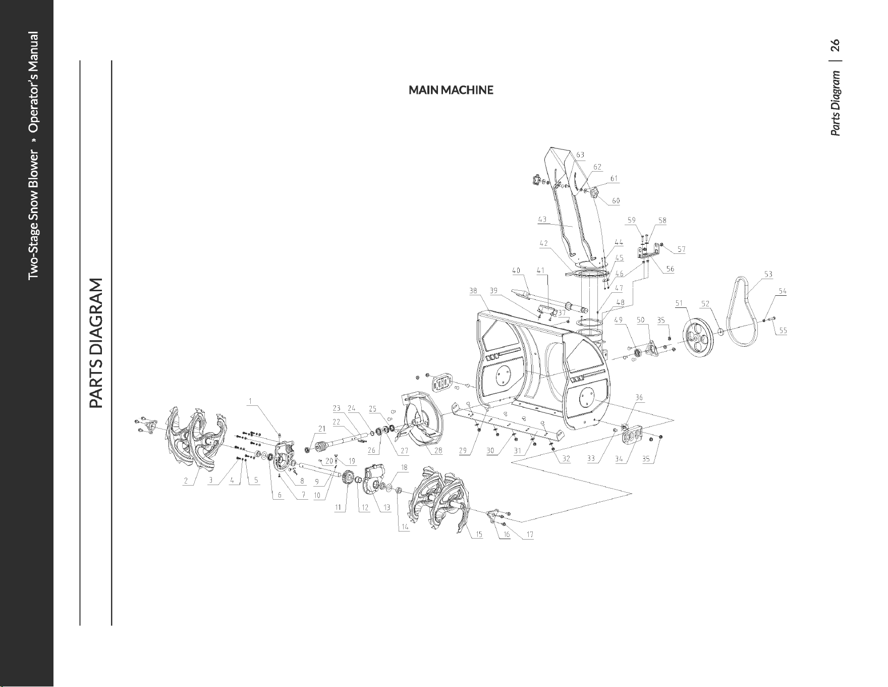
~
~
~
0
(./)
~
~
~
MAIN MACHINE
38
11].
~
~
~----~----~----~>
~~
-
\__1l~
53
-o
N
E
e
.~
a
t
~
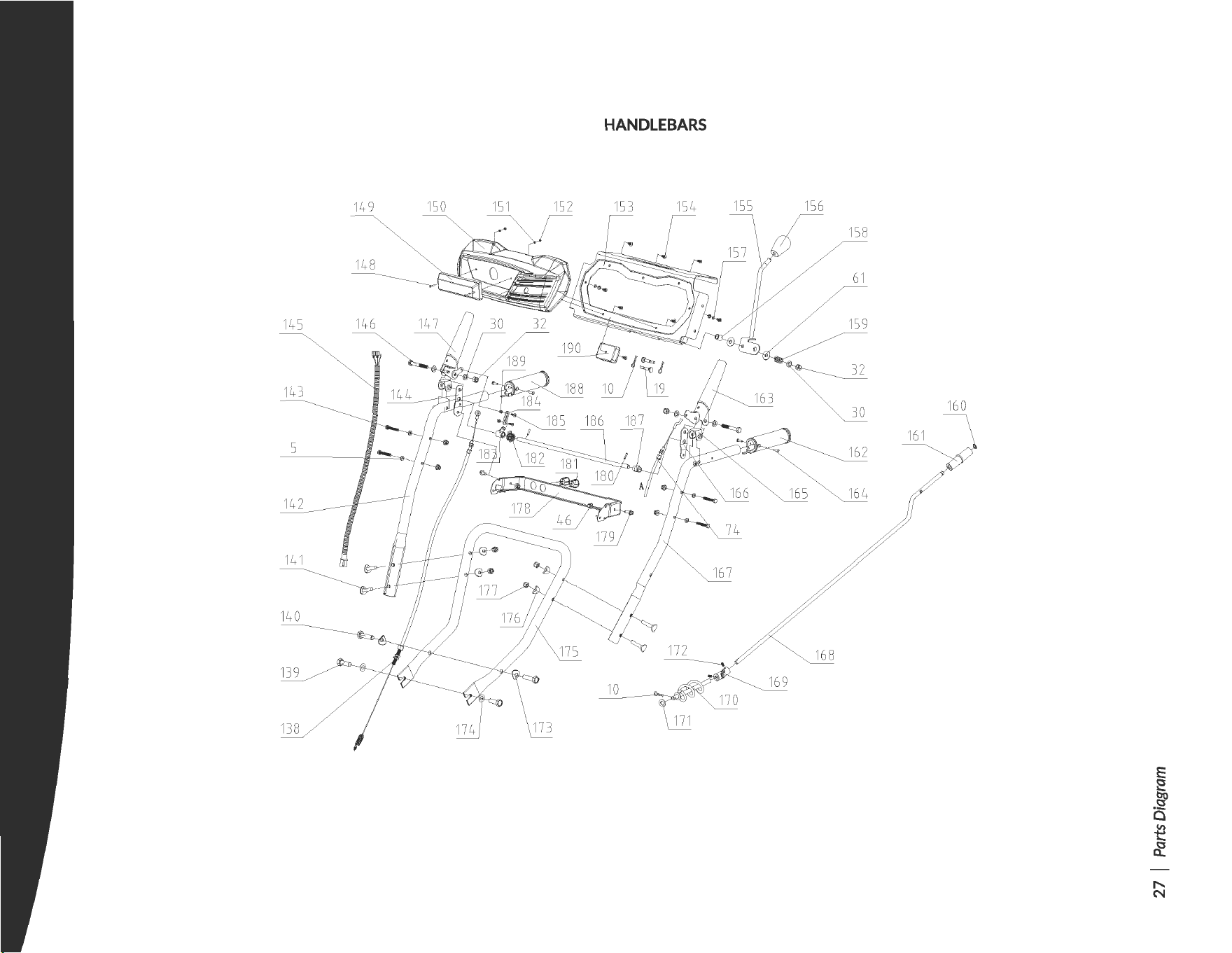
HANDLEBARS
155
145
1
43
5
1
56
160
E
~
~
a
t
~
.......
N
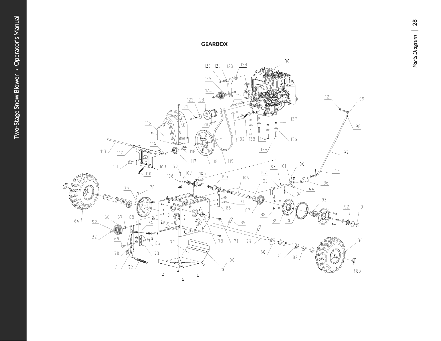
GEARBOX
130
129
12
99
91
co
N
E
e
.~
a
t
~

PARTS
LIST
No.
Description
Qty
No.
Description
Qty
No.
Description
Qty
1
Oil
Seal
M10x1
1
37
Plug 1
73
Auger Idler Mounting Bracket
1
2
Spiral Assembly-Right
1
38 Auger Housing
Assy.
1
74
Auger Belt Tensioning Cable
1
3
FT
Bolt
M6x20
6
39
Screw STS.Sx13
2
75 Big Gear
1
4
Spring
Washer
6
16
40
Chute Clean-Out Tool
1
76
PinA6x35
1
5
Flat Washer 6
17
41 Clean-Out
Tool
Mounting Bracket
1
77
Frame Cover
1
6
Seal
B20x35x7
2 42
Discharge Chute Ring 1
78 Gearbox Main Frame
1
7
ScrewMSxlO
1 43
Discharge Chute 1
79
Wheel Shaft
1
8
Auger Gearcase Housing-Right 1
44
FT
Bolt
M6x30
7
80
Shaft Bushing
2
9
Auger Shaft
1 45
Chute Flange Keeper 3
81 Shaft Spacer
2
10
Clevis
Pin
1.8
7 46
Flange Lock
Nut
M6
13
82 Wahser
3
11
Worm
Wheel
1
47
ScrewMSx6
2
83
Lock
Pin8
2
12 Shaft Sleeve
2 48 Discharge Chute Washer
1
84
Left Wheel ( Black)
1
13 Auger Gearcase Housing-Left
1
49
Ball Bearing 6203-2RS
1
I
85
Pin6x36
2
14
Washer
2
50
Bearing Housing 1
86
Auger Cable Holder
1
15
Spiral Assembly-Left
1
51 Auger Pulley 1
87
ShiftArm
1
16
Bearing Box
2
52 Big Flat Washer 8 1
88
FT
Bolt
M6x10
8
17
Screw ST8x16
6
53 Auger Belt 4LXP960 1
89
Friction Wheel Side Plate
2
18
Big Washer
2
54
Spring Washer 8 1
90
Rubber Ring
1
19 ShearPin
2
55
BoltM8x25
1
91
SnapRing15 3
20
Half Round Key Sx7.5x19
1
56
Rotating
Mount
Seat
1
92
Ball Bearing 60203-2RSn
2
21
Ball
Bearing6001-2RS
1
57
Bushing
2
93 Friction Wheel Hub
1
22
Roll
Pin6x37
2 58 Flat Washer 6
2
94
Clevis
Pin
2
1
23
Impeller Shaft
1
59
FT
Bolt M6x25
3
95 Thick Lock
Nut
M6
1
24
Washer
1
60
Chute Deflector Lock Knob 1
96 Sleeve
1
25
Seal
B20x35x7
1
61 Flat Washer 8
4
97 Gear Shifting Lever
1
26
Ball Bearing61904-2RS
1
62
Lock Washer
2
98
NutM10
1
27 Thrust Bearing 51104
1
63
BoltM8x20
1
99 SpinAxis
1
28
Impeller Assembly
1
64
Right Wheel ( Black)
1
100
Screw
M6x16
10
29 Bolt M8x16
5 65 Flat Washer 8 8
101 Fork Bracket
1
30
Flat Washer 8
13
66 Auger Idler 1
102 Fork Assembly
1
31
Shave
Plate
1
67
Spacer
1
103 Circlip 35
1
32 Lock
Nut
M8
10 68
FT
Bolt
M8x35
1
104
HexShaft
1
33 Bolt
M8x20
5
69
Pivot Bolt
1
105 Circlip
40
2
34
SkidShoe
2
70
Screw
M8x16
12
106
Cable Support Bracket
1
35
Hex. Flange
Nut
M8
7 71 Auger Idler Bracket
1
107
Cable Roller
1
36 Bolt M8x25
2 72 Extension Spring
1
108 Roller Bushing
1
29
I
PARTS
LIST

Two-Stage Snow Blower » Operator's Manual
No.
Description
Qty No.
Description
Qty
No.
Description
Qty
109 Driven Pulley Bracket
1
145
Output
Wire
(Light+
Heated
Grip)
1
181 Switch 2
110 Friction Wheel Retaining Spring
1 146 Bolt M8x60 2
182
Shaft
Torsional
Spring
1
111 Flange Lock
Nut
M16
1 147 Drive Clutch Lever (Right) 1
183 Interlock Raker 1
112
Locating
Knot
2 148 Screw M3x20 2
184
Connecting
Rod
1
113 Locating Shaft
1 149
LED
Light 1
185 Screw M4x12 2
114 Lock
Nut
M10
2 150 Dashboard 1
186 Interlock Shaft 1
115 Engine Belt Cover
1 151 Flat Washer 3 2
187 Interlock
Cam
1
116 Driven Pulley Hub
1 152 Thick Lock
Nut
M3
2
188 Heated Handle Grip- Right
1
117 Ball Bearing 6006-2RS
1 153 Dashboard Seat Weldment 1
189 Lock
Nut
M4
1
118 Engine Pulley
1 154 Screw 4.8x10 7
190 Plastic Box 1
119 Drive Belt 1 155
Speed
Shift Lever 1
120 Key 6x6x45 1 156
Speed
Shift Lever Grip 1
121 Spring Washer
10
1 157 Washer 5 4
122 Washer 1
158 Bushing
1
123 Belt Pulley
1
159 Return Pressure Spring
1
124 Drive Clutch Idler 1
160 Circlip
10
1
125 Bushing
1 161 Chute Crank Lever Knob 1
126 Bolt 5/16-24unf
1
162 Heated Handle Grip- Left
1
127 Drive Clutch Idler Bracket 1 163 Auger Clutch Lever ( Left) 1
128
FT
Bolt M8x30 1 164 Rivet 4x16 4
129
Spacer
1 165 Handle Spacer 2
130 Engine
1
166
Operation Handle Connecting
1
Plate- Left
131 Bolt 5/16-24unf 2
167 Operation Handlebar- Left
1
132 Belt Blocker 1
168 Chute Crank Lever 1
133 Extension Spring 1
169 Universal Joint 1
134
Jam
Nut
5/16-24unf 1
170 Spiral Weldment
1
135
FT
Bolt M8x35 4
171 Washer
10
1
136 Flat Washer
10
7
172 Screw M5x10 2
137 Flange Lock
Nut
M8
4
173 Arc Washer
10
6
138 Friction Wheel Cable 1
174 Washer
10
2
139FT
Bolt M10x20 2
175 LowerHandle 1
140
FT
Bolt M10x40 2
176 Arc Washer 8 4
141 Bolt M8x45 4
177 Thick Lock
Nut
M8
4
142 Operation Handlebar- Right 1
178
Dashboard Support Plate
143
FT
Bolt M6x40 1
Weldment
1
144
Operation Handle Connecting
1
179 Screw M6x12 2
Plate- Right
180 Elastic Cylindrical
Pin
3x16 2
PARTS
LIST
I 30

t>
BI[J
®
~~
3D INTERACTIVE INSTRUCTIONS
0
~
F 0 R T H I s p R 0 D u c T c A N B E F 0 u N D 0 N
DOWNLOAD
THE
FREE
APP
~
1-844-927-3629
