ELECTRIC START
2-STAGE SNOW BLOWER
Instruction Manual
MODEL SB24E
IMPORTANT: Your new tool has been engineered and manufactured to WEN’s highest standards for dependability,
ease of operation, and operator safety. When properly cared for, this product will supply you years of rugged,
trouble-free performance. Pay close attention to the rules for safe operation, warnings, and cautions. If you use
your tool properly and for its intended purpose, you will enjoy years of safe, reliable service.
NEED HELP? CONTACT US!
Have product questions? Need technical support? Please feel free to contact us:
TECHSUPPOR[email protected]1-800-232-1195 (M-F 8AM-5PM CST)
For replacement parts and the most up-to-date instruction manuals, visit WENPRODUCTS.COM
EPA III CERTIFIED

2
CONTENTS
WELCOME 3
Specifications ................................................................................................... 3
Introduction ..................................................................................................... 4
SAFETY 5
Safety Information ........................................................................................... 5
Snow Blower Safety Warnings ......................................................................... 6
Electrical Information ....................................................................................... 9
BEFORE OPERATING 9
Unpacking & Transportation ............................................................................ 9
Know Your Snow Blower................................................................................ 11
Assembly & Adjustments ............................................................................... 12
Snow Blower Preparation ............................................................................... 15
OPERATION & MAINTENANCE 18
Starting Your Snow Blower .............................................................................18
Operation ....................................................................................................... 20
Adjustments ................................................................................................... 22
Maintenance ................................................................................................... 23
Troubleshooting Guide ................................................................................... 29
Exploded View & Parts List ............................................................................ 31
Warranty Statement ....................................................................................... 43
To purchase accessories for your tool, visit WENPRODUCTS.COM
Magnetic Oil Dipstick (Model No. 55201), 100-Foot Extension Cord (Model No. PC1123),
50-Foot Extension Cord (Model No. PC5124), High-Altitude Kit (Part No. SB24E-HA).

SPECIFICATIONS
Model Number SB24E
Stages 2-Stage
Maximum Clearing Width 24 inches
Maximum Clearing Height 21 inches
Tire Size 13 x 4.10 - 6
Recommended Tire Pressure 20 - 24 PSI (137.9 - 165 kPa)
Wheel Valve Type Schrader
Speeds 4 Forward, 2 Reverse
Chute Range of Motion 190 degrees
Weight 172 lbs
Product Dimensions 52.5 x 25.65 x 43.9 inches
3
Engine Type
4-Stroke, OHV, Single-Cylinder with
forced-air cooling system
Engine Displacement 212cc
Fuel Tank Capacity 0.58 gallons (2.19 L)
Oil Capacity 20.3 fl. oz (0.6 L)
Runtime up to 2.75 hours
Lubrication System Splash Lubrication
Spark Plug Type Torch F7RTC (NGK BPR7ES)
Spark Plug Gap 0.7 - 0.8 mm (0.028 - 0.031 inches)
Spark Plug Torque
18.5 – 22 ft-lb (25 – 30 Nm), or ½
– ¾ turn after gasket contacts spark
plug hole
Electric Start 120VAC, 11A, Onboard Receptacle
ENGINE
SNOW BLOWER
4
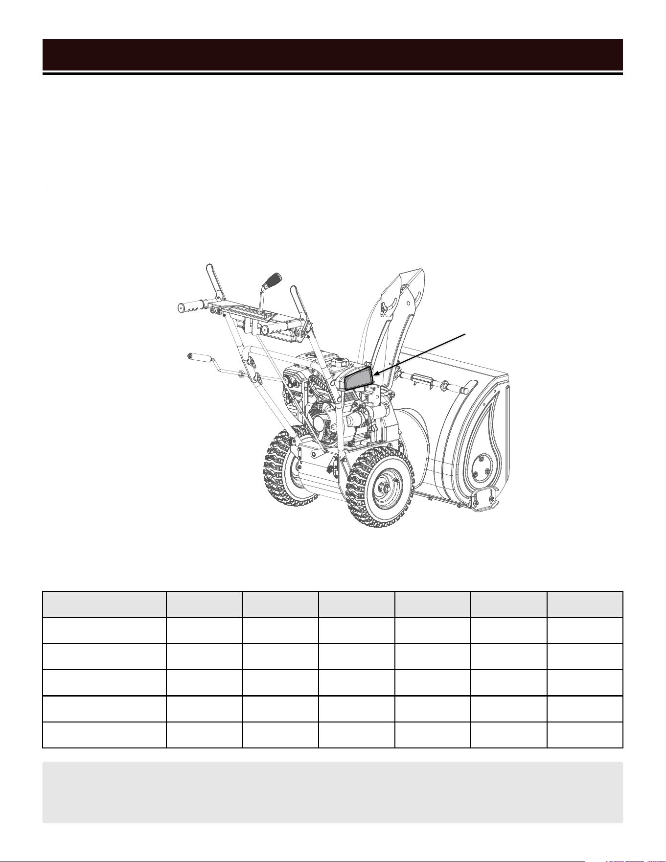
INTRODUCTION
Thanks for purchasing the WEN snow blower. Refer to the illustration below for the location of the serial number
on the side of the gas tank. Record the snow blower information in the spaces provided below. If assistance for
information or service is required, please contact customer service by calling 1-800-232-1195, M-F 8-5 CST; you
will be asked to provide the following snow blower information when calling.
Snow Blower Model Number: SB24E
Date of Purchase: ______________________________________________
Purchased From: _______________________________________________
Serial Number: ________________________________________________
TO MAXIMIZE THE LIFESPAN OF YOUR SNOW BLOWER: We recommend running your snow blower at least
once a month for 20 to 30 minutes. Start the snow blower according to the instructions and plug a small load
in to make sure the outlet is producing electricity.
SERVICE RECORD
Record the service dates of your snow blower in the chart below. Please perform maintenance checks and opera-
tions according to this manual. Refer to "Maintenance" on page 23.
Service Record Date Date Date Date Date Date
Change Oil
Change Spark Plug
Drain Fuel Tank
Check Tires
Clean Spark Arrestor
Serial
Number

5
SAFETY INFORMATION
WARNING: Before operating the snow blower, make sure to read all safety warnings and all instructions.
Failure to follow the warnings and instructions may result in electric shock, fire or serious injury.
SAFETY INTRODUCTION
Safety is a combination of common sense, staying alert, and knowing how your tool works. This manual contains
important information regarding the snow blower’s potential safety concerns, as well as preparation, operation,
and maintenance instructions. Before operating this snow blower, be sure to read and observe all warnings and
instructions both on the snow blower labels and in this instruction manual. Failure to follow all instructions listed
below may result in personal injury.
NOTE: The following safety information is not meant to cover all possible conditions and situations that may occur.
WEN reserves the right to change this product and specifications at any time without prior notice.
At WEN, we are continuously improving our products. If you find that your tool does not exactly match this manual,
please visit wenproducts.com for the most up-to-date manual or contact customer service at 1-800-232-1195,
M-F 8-5 CST.
Keep this manual available to all users during the entire life of the tool and review it frequently to maximize
safety for both yourself and others.
SAVE THESE SAFETY INSTRUCTIONS.
SAFETY SYMBOLS
The purpose of following safety symbols is to attract your attention to possible dangers. The safety symbols, and
their explanations, deserve your careful attention and understanding. The safety warnings do not by themselves
eliminate any danger. The instructions or warnings they give are not substitutes for proper accident prevention
measures.
NOTICE REGARDING EMISSIONS
Engines that are certified to comply with U.S. EPA emission regulations for SORE (Small Off Road Equipment), are
certified to operate on regular unleaded gasoline, and may include the following emission control systems: (EM)
Engine Modifications and (TWC) Three-Way Catalyst (if so equipped).
QUESTIONS? PROBLEMS?
In order to answer questions and solve problems in the most efficient and speedy manner, contact customer
service at 1-800-232-1195, M-F 8-5 CST or email [email protected].
DANGER: indicates a hazard, which, if not avoided, will result in death or serious injury.
WARNING: indicates a hazard, which, if not avoided, could result in death or serious injury.
CAUTION: indicates a hazard, which, if not avoided, might result in minor or moderate injury.
CAUTION: when used without the alert symbol, indicates a situation that could result in damage to the machine.

6
SNOW BLOWER SAFETY WARNINGS
DANGER: CARBON MONOXIDE
Using a snow blower indoors CAN KILL YOU IN MINUTES. Snow blower exhaust contains carbon monoxide
(CO). This is a poison gas you cannot see or smell. If you can smell the snow blower exhaust, you are breathing
CO. But even if you cannot smell the exhaust, you could be breathing CO.
NEVER use a snow blower inside homes, garages, crawl spaces, or other partially enclosed areas. Deadly
levels of carbon monoxide can build up in these areas. Using a fan or opening windows and doors does NOT
supply enough fresh air. ONLY use a snow blower outside and far away from windows, doors, and vents. These
openings can pull in snow blower exhaust.
Even if you use a snow blower correctly, CO may leak into the home. ALWAYS use a battery-powered or battery-
backup CO alarm in the home. If you start to feel sick, dizzy, or weak after the snow blower has been running,
move to fresh air RIGHT AWAY. See a doctor. You may have carbon monoxide poisoning.
WARNING: RISK OF EXPLOSION. HIGHLY FLAMMABLE: This snow blower may emit highly flammable
and explosive gasoline vapors, which can cause severe burns or even death, if ignited. A nearby open flame can
lead to explosion even if not directly in contact with gasoline.
• Do not operate near open flame, heat, or any other ignition source. Do not smoke near the snow blower.
• Always operate on a firm, level surface.
• Always turn snow blower off before refueling. Allow the snow blower to cool for at least 2 minutes before
removing fuel cap. Loosen cap slowly to relieve pressure in tank.
• Do not overfill fuel tank. Gasoline may expand during operation. Do not fill to the top of the tank. Allow for
expansion. Always check for spilled fuel before operating.
• If fuel spills, move the snow blower at least 30 feet away from the spill and wipe clean any spilled fuel before
starting the engine.
• Empty fuel tank before storing or transporting the snow blower.
CALIFORNIA PROPOSITION 65 WARNING: This product contains chemicals and produces exhaust known
to the State of California to cause cancer, birth defects and other reproductive harm.

7
SNOW BLOWER SAFETY WARNINGS
OPERATING ENVIRONMENT
1. Using a snow blower indoors can kill you in min-
utes. Only use a snow blower outside and far away from
windows, doors and vents.
2. Do not smoke near the snow blower.
3. Do not operate near open flame, heat, or flamma-
ble materials. This snow blower may emit highly flam-
mable and explosive gasoline vapors, which can cause
severe burns or even death if ignited. A nearby open
flame can lead to an explosion even if it isn’t directly in
contact with gasoline.
4. Thoroughly inspect the area where the snow blower
is to be used. Remove all doormats, newspapers, sleds,
boards, wires, extension cords, or any other foreign ob-
jects. Such objects pose a tripping hazard, or could be
thrown by the auger.
5. Maintain distance between the snow blower and
bystanders. Keep at least 75 feet away from bystand-
ers, pets, children, etc. Stop the machine if anyone en-
ters this area.
6. Thrown objects can cause serious personal injury.
Plan your snowblowing pattern to avoid discharge of
material towards roads, bystanders, windows, walls,
cars, etc.
7. Exercise caution to avoid slipping or falling, es-
pecially when operating in reverse. Wear appropriate
footwear.
8. Wear appropriate clothing for the weather condi-
tions. Wear ANSI Z87.1-approved eye protection, with
side shields, at all times. Do not wear jewelry, long
scarves, or loose clothing – these can become entan-
gled in moving parts. Wear hearing protection.
TRAINING
1. Read, understand, and follow all instructions on
your snow blower’s labels, as well as those contained
in this manual, before attempting to assemble, oper-
ate, maintain, or otherwise use your machine. Keep this
manual in a safe place and refer to it regularly. Ensure all
users of the machine are properly trained.
2. Familiarize yourself with all controls and their
proper operation. Know how to stop the machine and
disengage the controls quickly.
3. Do not allow children under 14 years old, or any
non-qualified person, to operate the machine. All op-
erators must be properly trained in the safe use of this
machine and follow all instructions on the machine and
in this manual. Children 14 years or older should be su-
pervised by a trained adult.
SNOW BLOWER PREPARATION
1. Do not overfill fuel tank, as gasoline may expand
during operation. Do not fill to the very top of the tank.
Leave room for gasoline expansion. Always check for
spilled fuel before operating.
2. If any part of the snow blower is broken, damaged,
or defective, make sure it is repaired or replaced be-
fore operation. Service should only be performed by a
qualified technician.
3. Never modify the snow blower in any way. Modi-
fying or using the machine for any other purpose for
which it is not designed may result in serious injuries,
machine damage and voiding of the warranty.
4. If using the electric start function, ensure the exten-
sion cord is rated for outdoor use. Use only a grounded
three-wire extension cord and receptacle. A GFCI outlet
is recommended to maximize safety.
Snow blower safety warnings continue
on the next page.
WARNING! Do not let comfort or familiarity with the product replace strict adherence to product safety
rules. Failure to follow the safety instructions may result in serious personal injury.

8 9
5. If using the electric start function, ensure the ex-
tension cord is of the proper gauge. Refer to the exten-
sion cord chart on p. 9 for the recommended gauge and
length of extension cord.
6. Disengage all control levers before starting the en-
gine.
7. Do not make any adjustments to the machine while
the engine is running.
8. Let the machine warm up for 1 – 2 minutes before
starting to clear snow.
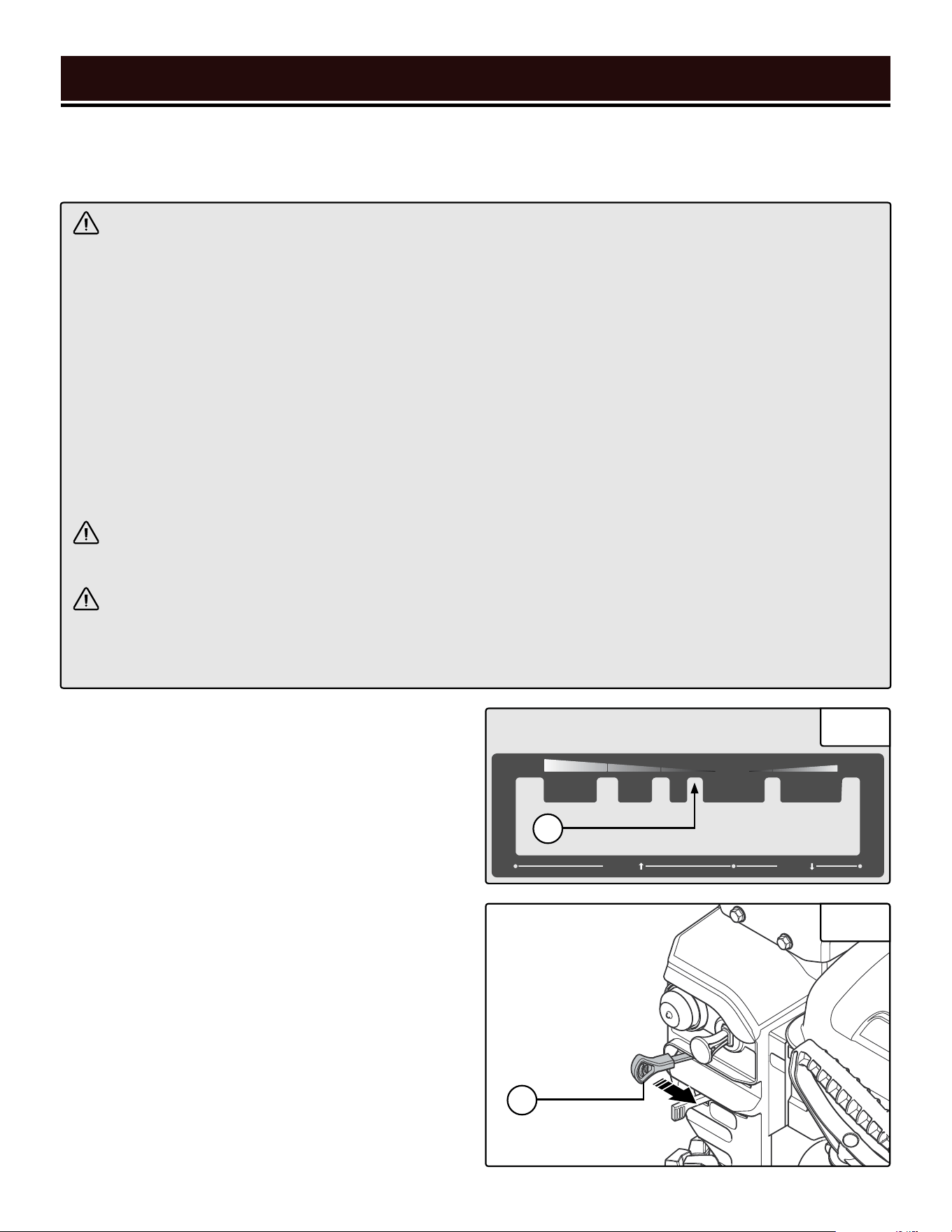
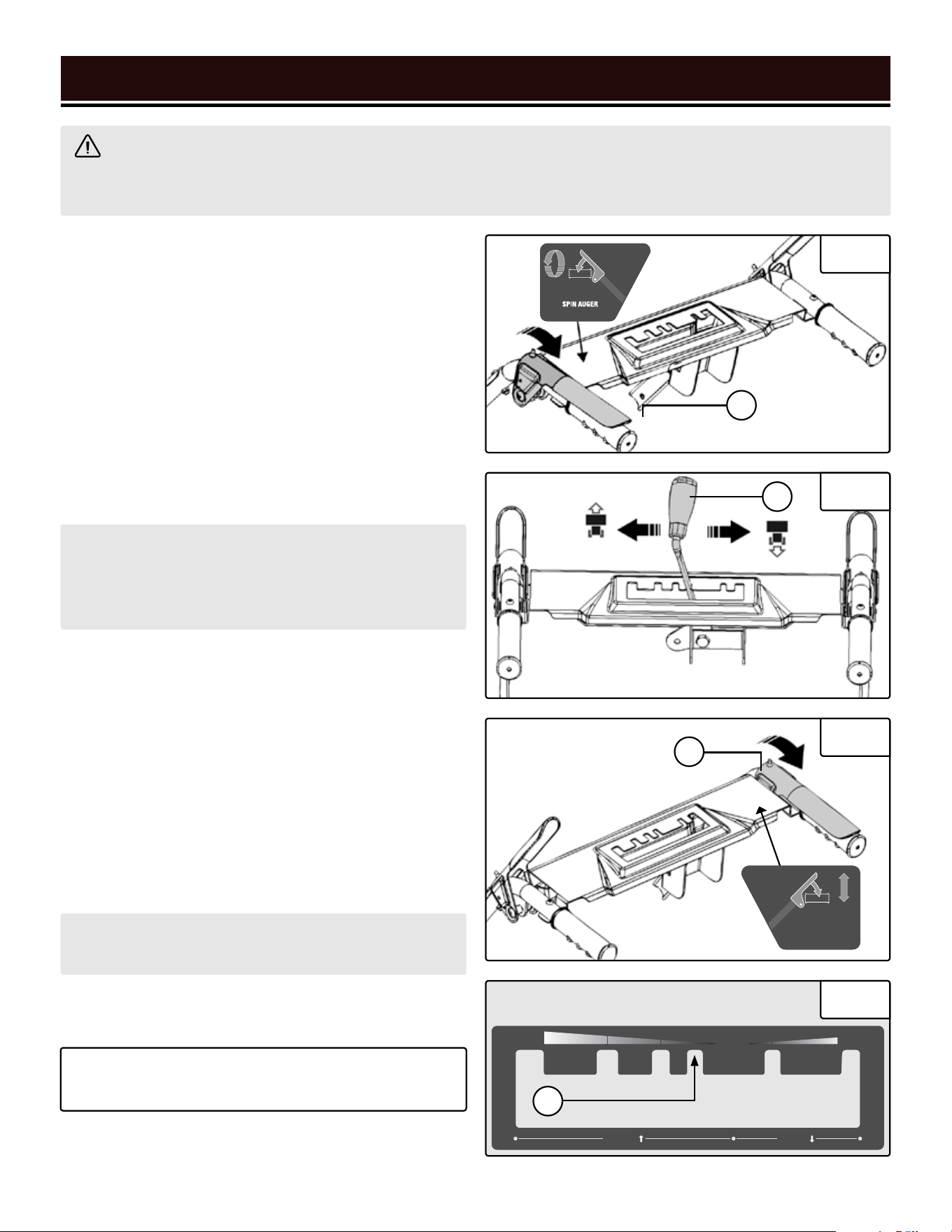
SNOW BLOWER OPERATION
1. Only use the snow blower for its intended purpos-
es. Modifying or using the snow blower for operations
for which it was not designed may cause hazards and
personal injury.
2. Do not touch hot parts. This snow blower produces
heat when running. Temperatures near exhaust can ex-
ceed 150ºF (65ºC). Allow snow blower to cool down
after use before touching engine or areas of the snow
blower that become hot during use.
3. Snow blowers vibrate in normal use. During and af-
ter the use of the snow blower, inspect the snow blower
for damage resulting from vibration.
4. Always turn snow blower off before refueling. Allow
snow blower to cool for at least 2 minutes before re-
moving fuel cap. Loosen cap slowly to relieve pressure
in tank.
5. Remove the engine key from the engine when the
engine is not running. Store it in a safe place out of the
reach of children.
6. Empty fuel tank before storing or transporting the
snow blower. Do not store snow blower or gasoline
near furnaces, water heaters, or any other appliances
that produce heat or have automatic ignitions. Store the
snow blower and fuel away from sparks, open flames,
pilot lights, heat and other sources of ignition.
7. Do not operate the machine under the influence of
alcohol, drugs, or other substances that could cause
lack of awareness.
8. Always wash hands after handling machine.
9. Never direct discharge at anyone, even if you think
it will be really funny.
10. Never put hands, feet, or other beloved body parts
near rotating parts, inside the auger housing, or into
the chute assembly, even if the engine is not running.
Use the included clean-out tool to clear out clogs.
11. Do not modify or bypass any safety devices. Keep
them in good working order.
12. Exercise extra caution when operating on, or
crossing, gravel or crushed-rock surfaces. Adjust the
skid plates and scraper bar appropriately when gravel or
crushed-rock surfaces are involved.
13. Do not operate on steep slopes (exceeding 15º in-
clination).
14. Do not overload the machine. Let it work at the
pace for which it was designed.
15. Disengage the auger lever when transporting the
product, or not clearing snow.
16. Operate only in good-visibility conditions. Keep
sure footing and a firm grip on the handles. Walk –
never run.
SNOW BLOWER SAFETY WARNINGS
WARNING! Do not operate the power tool until you have read and understood the following instructions
and the warning labels.
8
CAUTION: Misuse of this snow blower can damage
it or shorten its lifespan.
NOTE: This manual cannot possibly cover all situa-
tions that could occur. Always use common sense
and good judgment when operating the machine.
8 99
ELECTRICAL INFORMATION
AMPERAGE
REQUIRED GAUGE FOR EXTENSION CORDS
25 ft. 50 ft. 100 ft. 150 ft.
11A 16 gauge 16 gauge 14 gauge 12 gauge
GUIDELINES AND RECOMMENDATIONS FOR EXTENSION CORDS
When using an extension cord, be sure to use one heavy enough to carry the current your product will draw. An
undersized cord will cause a drop in line voltage resulting in loss of power and overheating. The table below shows
the correct size to be used according to cord length and ampere rating. When in doubt, use a heavier cord. The
smaller the gauge number, the heavier the cord. NOTE: "Amperage" below refers to the current that the starter mo-
tor draws.
1. Examine extension cord before use. Make sure your extension cord is properly wired and in good condition.
Always replace a damaged extension cord or have it repaired by a qualified person before using it.
2. Do not abuse extension cord. Do not pull on cord to disconnect from receptacle; always disconnect by pulling
on plug. Disconnect the extension cord from the receptacle before disconnecting the product from the extension
cord. Protect your extension cords from sharp objects, excessive heat and damp/wet areas.
3. Use a separate electrical circuit for your tool. This circuit must not be less than a 12-gauge wire and should
be protected with a 15A time-delayed fuse. Before connecting the motor to the power line, make sure the switch
is in the OFF position and the electric current is rated the same as the current stamped on the motor nameplate.
Running at a lower voltage will damage the motor.
TIP: WEN offers 12-gauge, outdoor-rated, grounded three-wire extension cords in 50-foot and 100-foot lengths
(Model No's. PC1123 & PC5124), available for purchase at wenproducts.com.
UNPACKING
With the help of a friend or trustworthy foe, carefully remove the snow blower from the packaging and place it on
a sturdy, flat surface. Make sure to take out all contents and accessories. Do not discard the packaging until every-
thing is removed. Check the packing list on the next page to make sure you have all of the parts and accessories.
If any part is missing or broken, please contact our customer service at 1-800-232-1195 (M-F 8-5 CST), or email
TRANSPORTING
To prevent fuel spillage when transporting, be sure to perform the following steps:
UNPACKING & TRANSPORTATION
WARNING! Do not plug in or turn on the tool until it is fully assembled according to the instructions. Failure
to follow the safety instructions may result in serious personal injury.
1. Tighten the fuel cap and turn the fuel valve to the
OFF position.
2. Remove the engine key and store it in a safe place.
3. Drain the fuel tank if possible. Refer to "Draining
The Fuel Tank" on page 27.
4. Keep the snow blower upright. Never place the
snow blower on its side or upside down - doing
so could damage the internal components of the
engine and make it difficult to start.
10
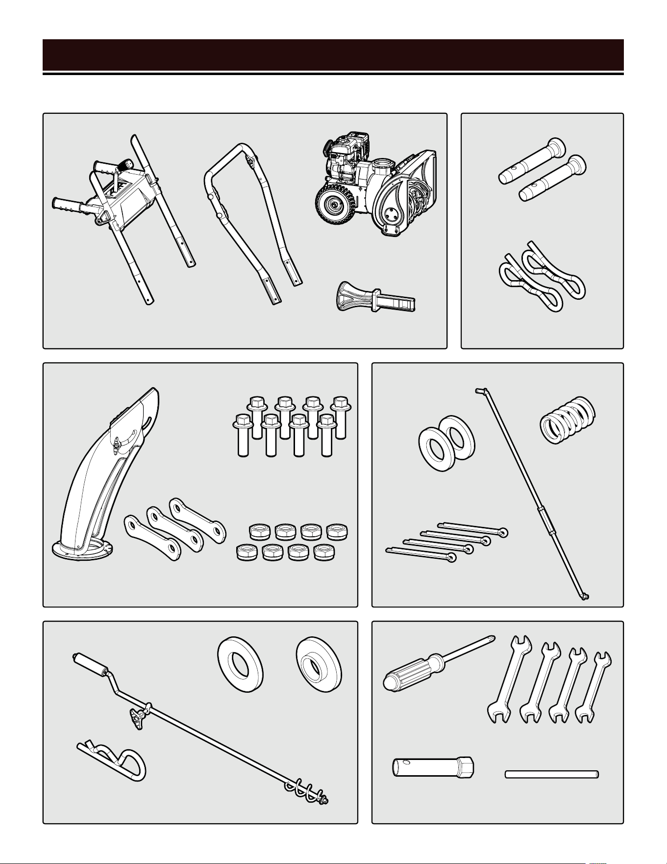
PACKING LIST
UNPACKING & TRANSPORTATION
Pre-Assembled
Chute Components Shift Lever Components
ToolsChute Rotator Components
Spare Parts
Upper Handle
Assembly (1)
Lower Handle
Assembly (1)
Flat Cotter Pin
(4 total - 2 spare)
8mm
Washer (2)
10mm
Washer (1)
Rotator
Seat (1)
Screwdriver
(1)
Open-End
Wrenches (4)
Chute
(1)
R Cotter Pin (1)
Chute Rotator (1)
M6x12 Bolt
(8 total - 2 spare)
Positioning
Plate (3)
Spring (1)
Rod
(1)
M6 Locking Nut
(8 total - 2 spare)
Snow Blower (1)
Engine Key (1)
Shear Pin (2)
Bowtie Clip (2)
Spark Plug
Wrench (1)
Spark Plug Wrench
Handle (1)
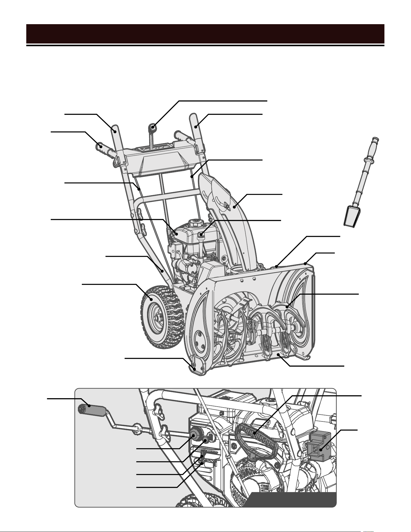
KNOW YOUR SNOW BLOWER
11
TOOL PURPOSE
Snow blowers allow you to clear snow quickly and efficiently. Refer to the following diagrams to become familiar-
ized with all the parts and controls of your snow blower. The components will be referred to later in the manual for
assembly and operation instructions.
Engine
Skid Plate
Auger Housing
Electric
Start Port
Recoil
Start Handle
Clearing Tool
Drive Lever
Chute
Rotator
Primer Button
Engine Key
Choke/Throttle
Fuel Switch
Handle
Scraper Bar
Auger Lever
Auger Cable
Shift Lever
Drive Cable
Lower Handle Assembly
Wheel
Chute
Oil Fill
Augers
User Controls Close-Up
12
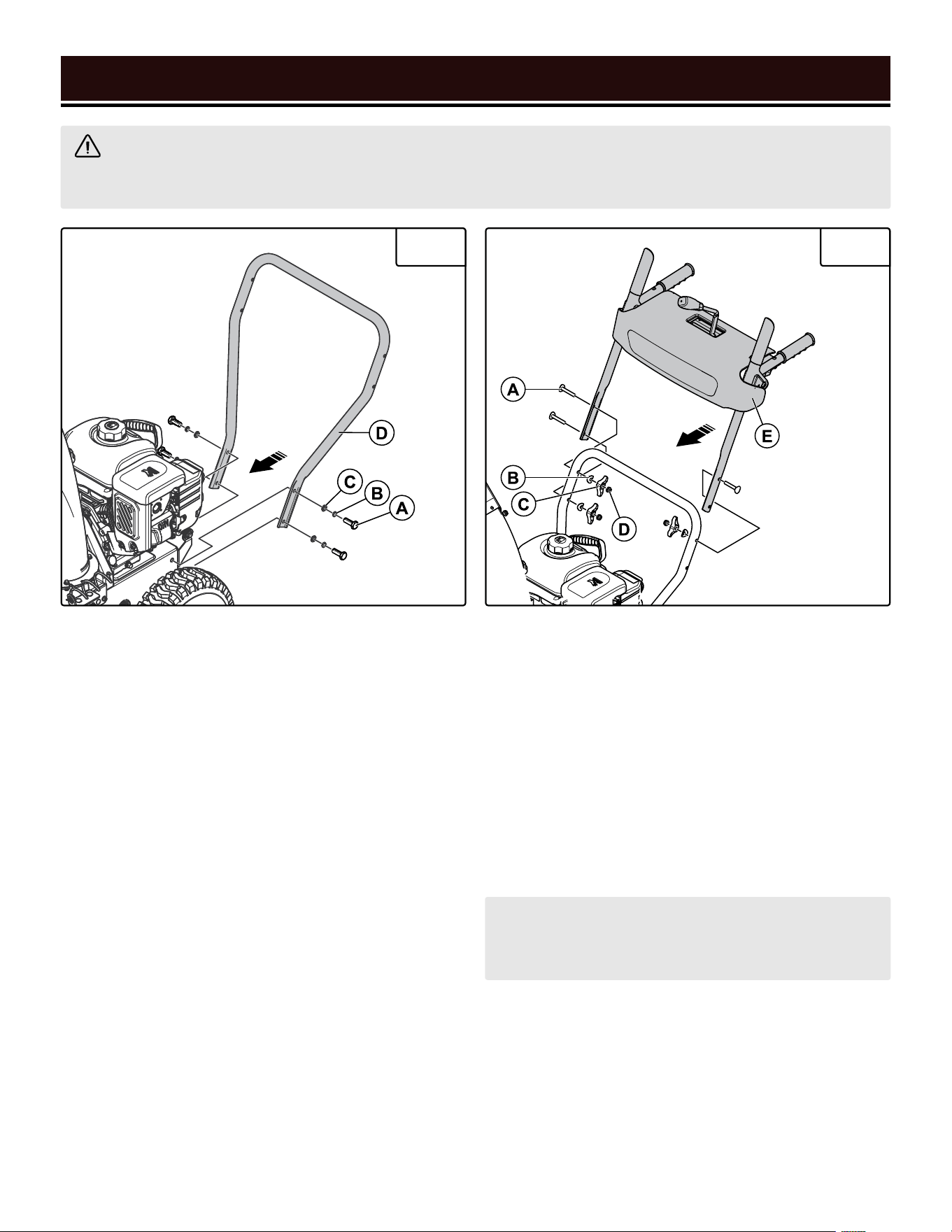
ASSEMBLY & ADJUSTMENTS
INSTALLING THE LOWER HANDLE (FIG. 1)
1. Remove the four M8x25 hex-head bolts (A), lock
washers (B), and flat washers (C) from the machine
casing.
2. Align the four holes on the lower handle (D) with the
holes on the machine casing.
3. Use the bolts and washers to secure the lower handle
to the casing.
WARNING! Do not plug in or turn on the tool until it is fully assembled according to the instructions. Read
through and become familiarized with the following procedures of handling and adjusting your tool. Failure to
follow the safety instructions may result in serious personal injury.
Fig. 1 Fig. 2
NOTE: Ensure that two knobs are installed on the
left side, and one on the right side (upper hole), as
shown.
INSTALLING THE UPPER HANDLE (FIG. 2)
To install the upper handle onto the lower handle, you
will need to used the pre-installed knobs on the lower
handle.
1. Remove the three M8x50 bolts (A), bent washers (B),
and knobs (C), and nuts (D) from the lower handle as-
sembly.
2. Use the bolts, bent washers, knobs, and nuts to se-
cure the upper handle assembly (E) to the lower handle
assembly, as shown.
13
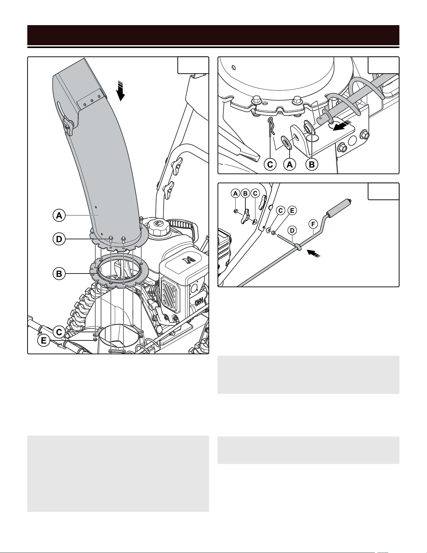
ASSEMBLY & ADJUSTMENTS
Fig. 3 Fig. 4
Fig. 5
INSTALLING THE CHUTE (FIG. 3)
1. Place the chute assembly (A) onto the rotator ring (B)
on the impellar housing.
2. Use the three positioning plates (C), six M6x12 bolts
(D), and six M6 locking nuts (E) to secure the chute as-
sembly to the rotator ring (B).
NOTE: Do not over-tighten the lock nuts, or the chute
will not be able to rotate. Rotate the chute assembly
by hand; if you find that the chute is difficult to ro-
tate, slightly loosen the lock nuts. Make adjustments
as necessary until the chute rotates freely, but does
not wobble, on the housing. It should be securely
mounted.
NOTE: Ensure that the spiral vanes on the chute ro-
tator handle assembly rest in the notches on the side
of the chute base.
NOTE: Adjust the nut on the eye bolt, if necessary, to
make it easier to assemble.
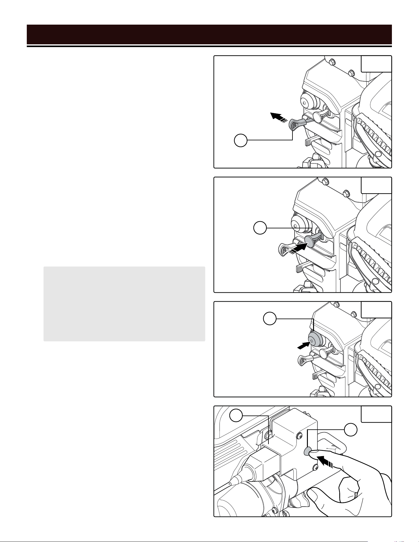
INSTALLING THE CHUTE ROTATOR HANDLE
ASSEMBLY (FIG. 4 & FIG. 5)
1. Assemble the front end of the chute rotator as shown
in Fig. 4, using the 10mm washers (A/B) and cotter pin
(C). Bend back the ends of the cotter pin to secure it.
2. Assemble the rear end of the chute rotator (F) as
shown in Fig. 5, using the bolt (A), knob (B), bent
washers (C), eye bolt (D), and nut (E).
3. Check that rotating the chute rotator handle causes
the chute to rotate. Adjust mounting nuts if necessary,
see "INSTALLING THE CHUTE (Fig. 3)" on page 13.
14
ASSEMBLY & ADJUSTMENTS
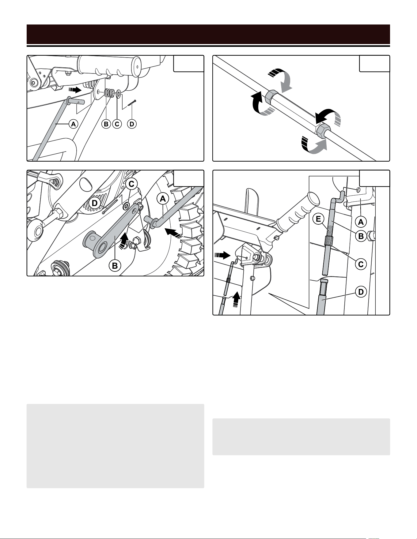
INSTALLING THE DRIVE CONTROL ROD
(FIG. 6, FIG. 7 & FIG. 8)
1. Refer to Fig. 6 for this step. Install the long end of the
drive control rod (A) into the hole on the shift lever. Se-
cure it using the spring (B), flat washer (C), and cotter
pin (D). Bend back the ends of the cotter pin to secure it.
2. Refer to Fig. 7 for this step. Pull up the transmission
connector plate (B) and install the short end of the drive
control rod (A) into the hole on the connector plate. Se-
cure it using the flat washer (C) and cotter pin (D). Bend
back the ends of the cotter pin to secure it.
INSTALLING THE CABLES (FIG. 9)
See page 11 for the proper location of the cables.
1. Remove the two cable screw bolts (B) from the ca-
bles (D).
2. Attach the cable screw bolts to the holes on the in-
sides of the left and right handles (A).
3. Attach the cable bottle screw (D) to the cable screw
bolts (B).
Fig. 6 Fig. 8
Fig. 9 Fig. 7
NOTE: If necessary, the drive control rod’s length can
be adjusted. The length has been set at the factory
and should not require further adjustment; however,
if you find it is absolutely necessary, loosen the hex
nuts, adjust the bottle screw appropriately, and then
tighten the hex nuts, see Fig. 9. For proper speed
control, the bottle screw should be adjusted back to
its original position (marked on the threads).
NOTE: Do not twist the cables themselves. Hold
the cable itself steady while turning the cable bottle
screw to attach it to the cable screw bolt.
4. Adjust the position of the brass locking nuts (C) until
they are aligned with the mark on the cable screw bolt
threads (E).
5. Adjust the position of the cable bottle screws until
they are flush against the brass locking nuts.
15
SNOW BLOWER PREPARATION
The following section describes the necessary steps to prepare the snow blower for use. If you are unsure about
how to perform any of the steps please call 1-800-232-1195 (M-F 8-5 CST) for customer service. Failure to per-
form these steps properly can damage the snow blower or shorten its life.
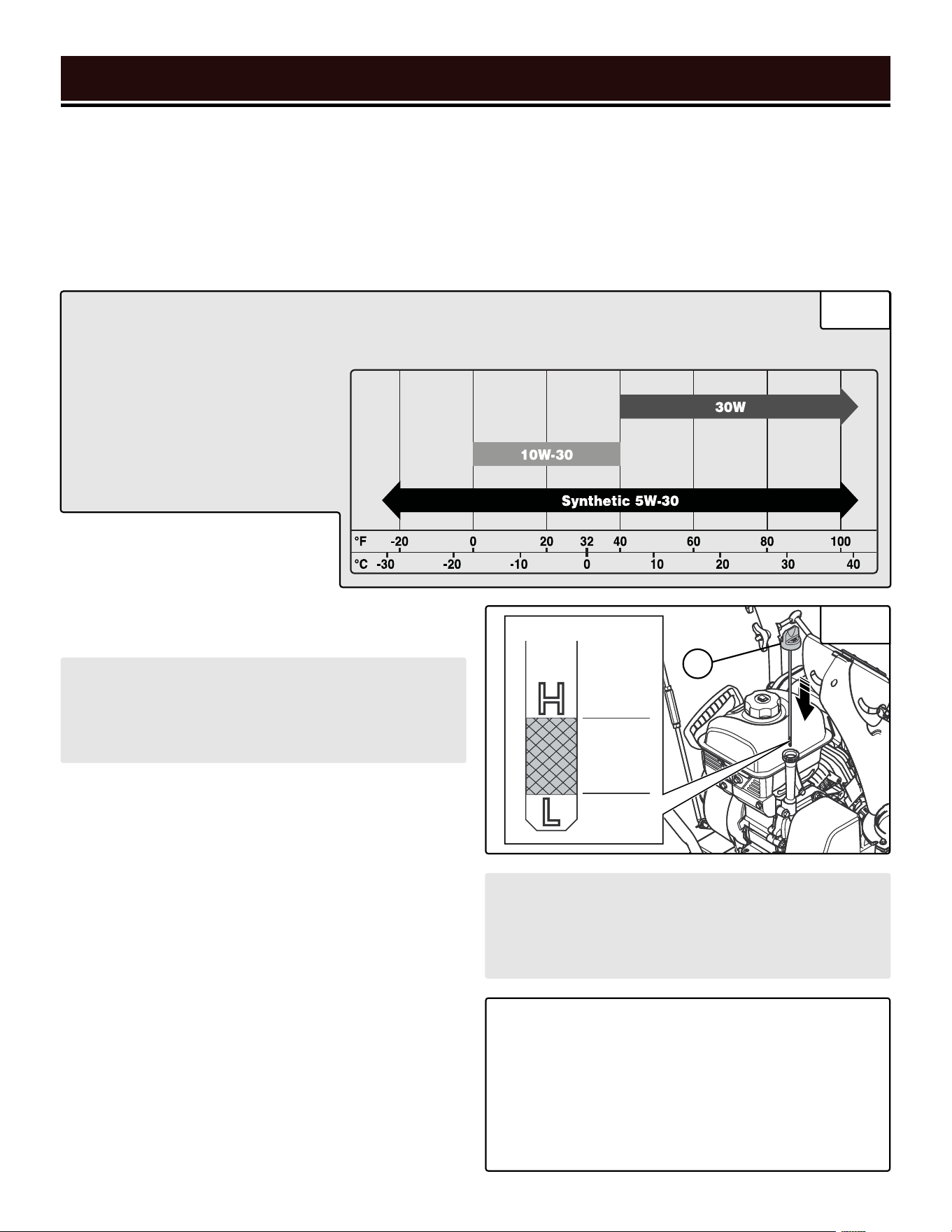
STEP 1 - ADD/CHECK OIL (FIG. 10 & FIG. 11)
The user must add the proper amount of oil before operating the snow blower for the first time. The oil capacity of
the engine crankcase is 20.3 fl. oz. (0.6 L).
• 30W Engine Oil
Temperatures above 40°F.
• 10W-30 Engine Oil
Temperatures between 0°F - 40°F.
• Synthetic 5W-30 Engine Oil
All temperature ranges.
ENGINE OIL RECOMMENDATIONS - Select good quality detergent oil bearing the American Petroleum Institute
(API) service classifications SJ, SL, or SM (synthetic oils may be used). Select the SAE viscosity grade of oil
that matches the expected operating temperature. For general use (above 40° F), we recommend using 30W engine oil.
Good
Oil
Level
CAUTION! Keep the snow blower level. Tilting the
snow blower to assist in filling will cause oil to flow
into the wrong areas of the engine and cause dam-
age.
CAUTION! For subsequent operation, the oil level
should be checked before each use, or after every
8 hours of operation. Follow the instructions on the
next page to check the oil level.
TO ADD OIL:
1. Place the snow blower on a level
surface. Make sure the engine is OFF
before adding or checking oil.
3. Using an oil funnel or appropriate dispenser, slowly
add oil into the oil fill, being careful not to overfill the
unit. Use the dipstick to check the oil level as you fill the
tank. The oil should reach the section between the up-
per (H) and lower (L) level. Reinstall the oil dipstick and
firmly tighten it. Wipe clean any spilled oil.
TO CHECK OIL LEVEL (before every subsequent start):
1. Place the snow blower on a level surface. Make sure
the engine is OFF before adding or checking oil.
2. Remove and wipe the dipstick (A) with a clean rag.
3. Insert the dipstick into the oil fill without screwing it
in. Remove the dipstick to check the oil mark.
4. If the oil mark does not reach the section between
the upper (H) and lower (L) mark on the dipstick, slow-
ly add oil until the oil mark reaches this section.
Fig. 10
Fig. 11
TIP: Your WEN snow blower is compatible with the
WEN 55201 Magnetic Oil Dipstick (not included),
available for purchase at wenproducts.com. The
dipstick’s industrial-strength magnetic tip will col-
lect metal shavings from your snow blower’s oil
tank to help preserve the engine and extend your
snow blower’s lifespan.
2. Unscrew the oil dipstick (A) from the engine.
A
1716
STEP 2 - ADD/CHECK FUEL (FIG. 12)
WARNING: RISK OF EXPLOSION. HIGHLY FLAMMABLE: This snow blower may emit highly flammable
and explosive gasoline vapors, which can cause severe burns or even death, if ignited. A nearby open flame can
lead to explosion even if not directly in contact with gasoline.
• Do not operate near open flame, heat, or any other ignition source. Do not smoke near the snow blower.
• Always operate on a firm, level surface.
• Always turn the snow blower off before refueling. Allow the snow blower to cool for at least 2 minutes be-
fore removing fuel cap. Loosen cap slowly to relieve pressure in tank.
• Do not overfill fuel tank. Gasoline may expand during operation. Do not fill to the top of the tank. Allow for
expansion. Always check for spilled fuel before operating.
• If fuel spills, move the snow blower at least 30 feet away from the spill and wipe clean any spilled fuel before
starting the engine.
• Empty fuel tank before storing or transporting the snow blower.
ONLY use fresh (within 30 days from purchase), lead-
free gasoline with a minimum of 87 octane rating. The
snow blower performs best with ethanol-free gasoline.
DO NOT use gasoline with over 10% ethanol.
The capacity of the fuel tank is 0.58 gallons. Do not mix
oil with gasoline.
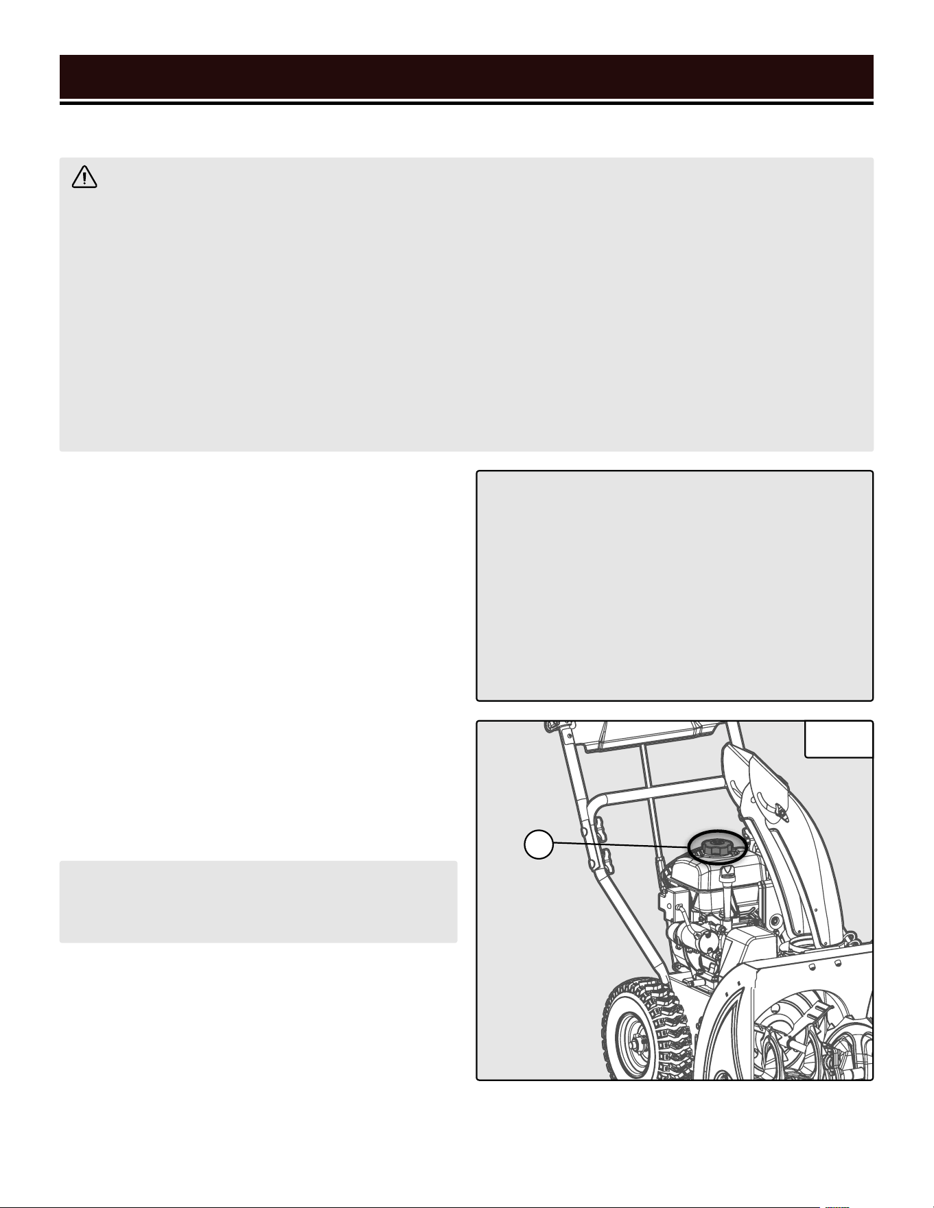
TO ADD GASOLINE:
1. Place the snow blower on a level surface. Make sure
the engine is OFF before adding or checking the fuel.
2. Unscrew the fuel cap (A) and set it aside. The fuel cap
may be tight and hard to unscrew.
3. Slowly add unleaded gasoline to the fuel tank. Be
careful not to overfill. Reinstall fuel cap and wipe clean
any spilled gasoline with a dry cloth.
IMPORTANT:
• Avoid getting dirt or water into the fuel tank.
• Keep gasoline away from sparks, open flames,
pilot lights, heat, and other sources of ignition.
• Gasoline can age in the tank and make starting
difficult. Never store the snow blower for more
than 2 months with fuel in the tank.
• Never use an oil/gasoline mixture.
• Never use old gasoline.
SNOW BLOWER PREPARATION
NOTE: Do not fill the fuel tank to the very top. If you
do so, gasoline will expand and spill during use,
even with the fuel cap in place.
Fig. 12
TO CHECK GAS LEVEL (before every subsequent start):
1. Before starting the snow blower, check to see if there
is sufficient fuel inside the tank.
2. If the tank is empty or low, add gasoline to the gas
tank. See above section, "To Add Gasoline".
A
1716
SNOW BLOWER PREPARATION
Fig. 13
Fig. 14
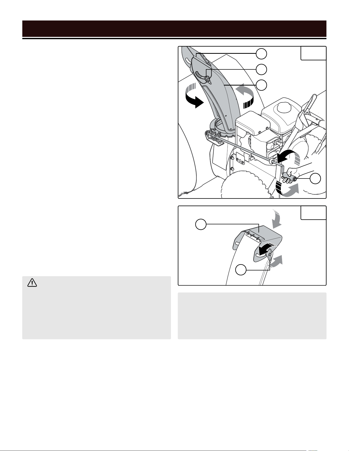
STEP 3 - ADJUST THE CHUTE & DEFLECTOR
PLATE (FIG. 13 & FIG. 14)
The direction in which snow is ejected is controlled
by the chute rotator handle (D). Turn the chute rotator
handle to adjust the position of the chute (C).
The angle at which snow is ejected (and therefore how
far it is ejected) is controlled by the chute deflector plate
(A). Loosen the two knobs (B) on the side of the de-
flector plate and adjust the plate’s position. Tighten the
knobs.
HIGH ALTITUDE OPERATION ABOVE 3000
FEET
The fuel system on this snow blower may be affected by
operation at high altitudes. Proper operation can be en-
sured by installing an altitude kit at altitudes higher than
3000 feet above sea level. At elevations above 8000
feet, the engine may experience a decrease in perfor-
mance, even with the proper altitude kit. Operating this
snow blower without said kit may increase the engine’s
emissions and decrease both fuel economy and perfor-
mance.
You can order the kit at wenproducts.com by searching
part SB24E-HA. This kit should be installed by a quali-
fied mechanic. Refer to the instructions included with
your altitude kit for more information about installation.
WARNING! To prevent serious injury from
fire, follow the kit installation procedures in a well-
ventilated area away from ignition sources. If the
engine is hot from use, shut the engine off and wait
for it to cool before proceeding. Do not smoke near
the snow blower. Warranty will be void if adjustments
are not made for high altitude use.
CAUTION! UNINSTALL the high altitude kit when op-
erating at altitudes below 3000 feet. Engines with the
high-altitude kit installed operated at lower altitudes
could cause severe engine damage and affect emis-
sions compliance.
After completing the above preparation, the snow blower is ready to be started.
D
A
A
B
B
C
1918
Before starting the snow blower, make sure you have read and performed the steps in the “Snow Blower Prepara-
tion” section of this manual, pages 15-17. If you are unsure about how to perform any of the steps in this manual
please call 1-800-232-1195 (M-F 8-5 CST) for customer service.
STARTING YOUR SNOW BLOWER
DANGER: CARBON MONOXIDE
Using a snow blower indoors CAN KILL YOU IN MINUTES. Snow blower exhaust contains carbon monoxide
(CO). This is a poison gas you cannot see or smell. If you can smell the snow blower exhaust, you are breathing
CO. But even if you cannot smell the exhaust, you could be breathing CO.
NEVER use a snow blower inside homes, garages, crawl spaces, or other partially enclosed areas. Deadly
levels of carbon monoxide can build up in these areas. Using a fan or opening windows and doors does NOT
supply enough fresh air. ONLY use a snow blower outside and far away from windows, doors, and vents. These
openings can pull in snow blower exhaust.
Even if you use a snow blower correctly, CO may leak into the home. ALWAYS use a battery-powered or battery-
backup CO alarm in the home. If you start to feel sick, dizzy, or weak after the snow blower has been running,
move to fresh air RIGHT AWAY. See a doctor. You may have carbon monoxide poisoning.
WARNING: The exhaust from this product contains chemicals known to the State of California to cause
cancer, birth defects, or other reproductive harm.
WARNING: Do not operate snow blower near open flame or flammable materials This snow blower may
emit highly flammable and explosive gasoline vapors, which can cause severe burns or even death if ignited.
A nearby open flame can lead to explosion even if it isn’t directly in contact with gasoline. Do not smoke near
the snow blower.
BEFORE STARTING YOUR SNOW BLOWER
1. Verify that the snow blower is outside on a level sur-
face with at least 2 feet of clearance on all sides.
2. Check that there is a sufficient level of oil in the crank-
case. Add oil if necessary, see "Step 1 - Add/Check Oil
(Fig. 10 & Fig. 11)" on page 15.
3. Check that there is a sufficient level of gasoline in the
fuel tank. Add fuel if necessary, see "Step 2 - Add/Check
Fuel (Fig. 12)" on page 16.
4. Check that the chute and deflector plate are pointing
in the desired direction. Adjust the chute and deflector
if necessary, see "Step 3 - Adjust The Chute & Deflector
Plate (Fig. 13 & Fig. 14)" on page 17.
STARTING THE SNOW BLOWER
1. Release the lever (right side). Put the shift lever in the
low, forward position (Fig. 15 - A).
2. Push the fuel switch (Fig. 16 - A) to the ON position.
FORWARD
REVERSE
FASTFAST SLOW
Fig. 15
Fig. 16
A
A
1918
STARTING YOUR SNOW BLOWER
STARTING THE SNOW BLOWER - CONTINUED
3. Push the choke lever (Fig. 17 - A) to the CLOSED/
START position.
4. Insert the engine key (Fig. 18 - A) fully into the key
slot (RUN position).
5. Push the primer bulb (Fig. 19 - A) 3 times. This helps
the engine start more easily in lower temperatures.
6. Follow step A for electric start, or B for recoil start.
A. For electric start:
i. Connect an extension cord to the electric start
port (Fig. 20 - A) above the starter motor. See
"Electrical Information" on page 9 for extension
cord guidelines.
ii. Press and hold the start button on the electric
start box for 5 seconds (Fig. 20 - B).
iii. If the engine does not start, wait 5 - 10 seconds,
then try again. Check that the adjustments in steps
1 - 5 have been performed properly.
Fig. 17
A
Fig. 18
A
Fig. 19
A
Fig. 20
B
A
CAUTION! Do not try to start the engine more
than 10 times. If after 10 times the engine does
not start, wait 40 minutes before trying again.
If problems persist, consult the troubleshoot-
ing guide on p. 29. If the steps in the guide do
not resolve the problem, call customer service
at 1-800-232-1195, M - F, 8 - 5 CST.
iv. Once the engine has started, slowly return the
choke lever all the way to the OPEN/RUN position.
v. Disconnect the extension cord from the wall re-
ceptacle, then from the electric start box.
B. For recoil start:
i. Pull on the recoil starter handle (see page 11 for
loaction) slowly until a slight resistance is felt, then
pull quickly to start the engine. Return cord gently
into the recoil starter. Never allow the cord to snap
back. If engine fails to start, repeat this step.
i. Once the engine has started, slowly return the
choke lever all the way to the OPEN/RUN position.
7. Allow the engine to run for 30 - 60 seconds before
beginning to clear snow.
CONTROLS
1. Squeeze the auger lever (Fig. 21 - A) to spin the auger
and throw snow. To adjust the position of the chute and
chute deflector plate, see "Step 3 - Adjust The Chute &
Deflector Plate (Fig. 13 & Fig. 14)" on page 17.
2. The direction and speed of the snow blower’s motion
is controlled by the shift lever (Fig. 22 - A). There are
four speed settings in forward (towards the left) and
two in reverse (towards the right).
3. Squeeze the drive lever (Fig. 23 - A) to allow the
wheels to spin and move the snow blower.
OPERATION
WARNING! Do not plug in or turn on the tool until it is fully assembled according to the instructions. Read
through and become familiarized with the following procedures of handling and adjusting your tool. Failure to
follow the safety instructions may result in serious personal injury.
20
TURNING THE SNOW BLOWER OFF
1. Release the auger and drive levers.
2. Put the shift lever in the low, forward position (Fig.
24 - A).
3. Run the auger for 30 - 60 seconds to clear out any
remaining snow inside the auger housing or chute, then
release the auger lever.
4. Turn the fuel lever to OFF. This burns the fuel out of
the carburetor and prolongs engine life.
Fig. 21
A
Fig. 22
A
A
Fig. 23
CAUTION! Always disengage the drive engagement
handle before changing speeds! Failure to perform
this step could lead to clutch or transmission dam-
age and will void the warranty.
NOTE: To shut down the engine immediately, pull the
engine key out.
TIP: turn the chute through its full range of motion a
couple of times to prevent ice buildup.
FORWARD
REVERSE
FASTFAST SLOW
Fig. 24
A
5. Remove the engine key. Store it in a safe place out of
the reach of children.
MOVE
FORWARD/BACKWARDS
21
OPERATION
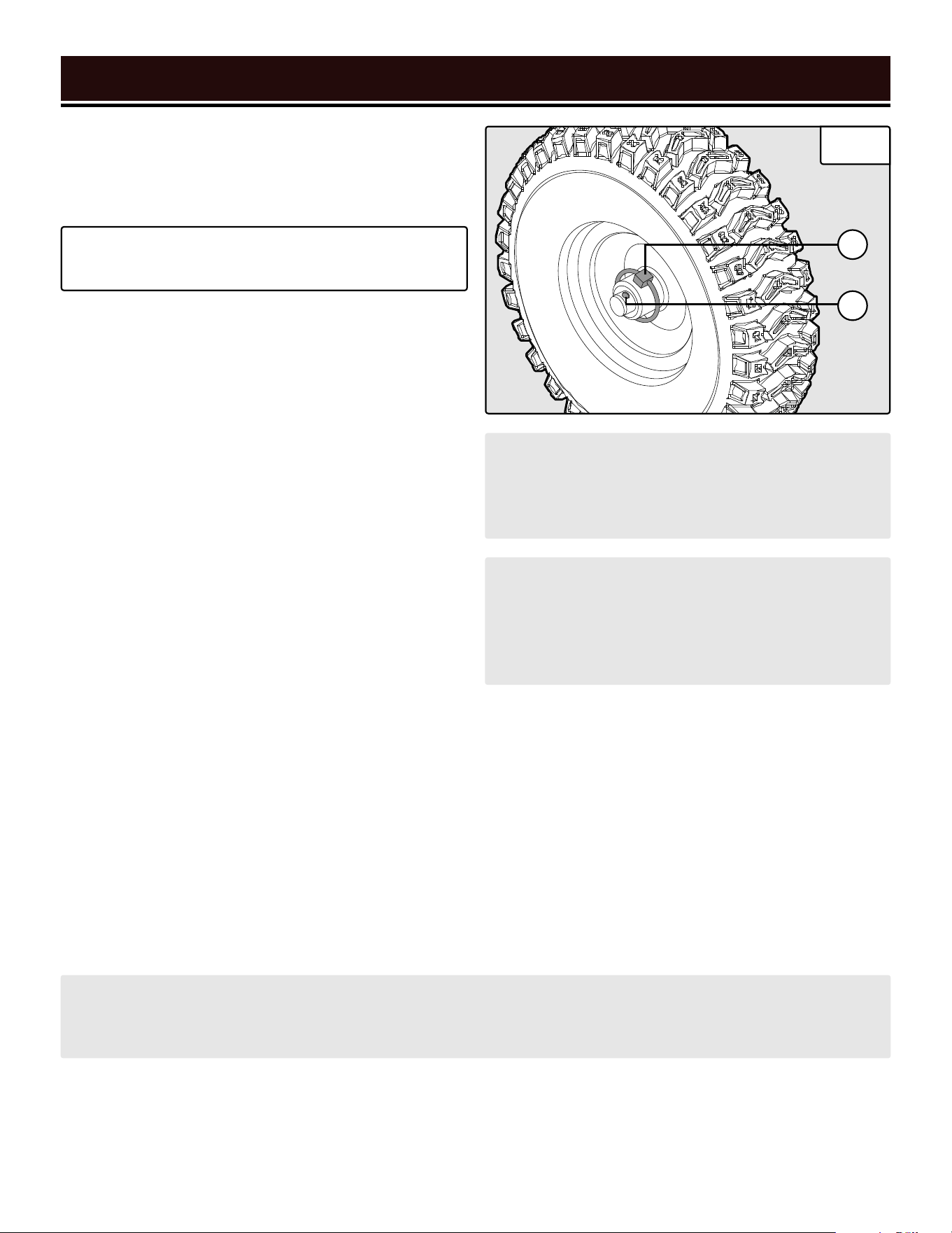
ADJUSTING WHEELS FOR TURNS (FIG. 25)
Your snow blower is capable of making tight turns when
snow blowing. To do this, adjust the click pins as in-
structed below.
Fig. 25
A
B
CAUTION! Use extra care when engaging the drive
system. If a wheel is disengaged, it will rotate in-
dependently of the axle, and the snow blower will
tend to pull toward that side when the drive system
is engaged (since it is only driving the other wheel).
NOTE: the auger blades are mounted to their shaft with shear pins that are designed to break if a foreign object
enters the auger housing. This is to prevent machine damage and operator or bystander injury. For information
on replacing the shear pins, see "Replacing Shear Pins (Fig. 27)" on page 24.
WARNING! NEVER run the snow blower without in-
stalling the click pin into the outermost hole of the
axle. Ensure that both click pins are present and ad-
justed appropriately.
TIP: It is best to perform these steps in the comfort
of your garage, before you’ve gone out into the cold.
1. Plan your snow blowing route. If you will be mostly
turning to the left, perform the steps below on the left
wheel; if you will mostly be turning to the right, perform
the steps on the right wheel.
2. Locate the click pin (A) on the axle. Flip the pin’s cir-
cular handle up and remove the click pin from the axle.
3. Insert the click pin into the outermost hole (B) on the
axle and flip the circular handle down. This disengages
the wheel from the axle and allows the wheel to rotate
independently, making turning much easier.
4. To re-engage a wheel with the axle, align the hole on
the hub with the hole on the axle. Insert the click pin
through the hub and the axle. Flip the circular handle
down. The wheel and axle are now re-engaged and will
rotate together.
TIPS FOR EFFECTIVE SNOW BLOWING
• Always run the engine at full throttle.
• Adjust the drive speed to the situation at hand. Let the machine do the work.
• It is easier and more efficient to remove snow immediately after it falls.
• Throw snow downwind whenever possible.
• Don’t use the snow blower early in the morning, if possible. You know how your neighbor Greg is about noise.
• On flat surfaces (such as concrete, asphalt, etc.), adjust the skid plates so that the bottom of the scraper bar
runs along the ground. See"Adjusting The Skid Plates (Fig. 26)" on page 22.
• On uneven surfaces (such as gravel, crushed rock, etc.) raise the scraper bar slightly above the top of the
gravel surface. Ensure that gravel and stones do not enter the auger housing, as they could cause injuries if
they are ejected.
• Clear clogs immediately, see "Clearing Clogs" on page 22.
• If the auger or drive do not engage when the handle is squeezed, release it immediately and turn the engine OFF.
22
OPERATION
ADJUSTMENTS
CLEARING CLOGS
A clearing tool is included with your snow blower and can be mounted in the clasp on the auger housing for easy
access.
1. Turn the engine OFF and wait for all moving parts (wheels, impeller, auger blades, etc.) to stop moving.
2. Use the clearing tool to clear the clog.
3. Replace the clearing tool in the clasp on the auger housing.
ADJUSTING THE SKID PLATES (FIG. 26)
The skid plate setting controls how far above the ground
the scraper bar operates. When operating on concrete,
asphalt, or other smooth surfaces, adjust the skid plate
so that the bottom of the scraper bar rides along the
ground. When operating on gravel, dirt, crushed rock, or
other uneven surfaces, adjust the skid plate so that the
bottom of the scraper bar rides just above the ground,
to prevent debris from entering the auger. Surfaces with
larger, coarser debris (e.g. larger pieces of gravel) re-
quire a more-raised scraper bar. NOTE: The skid plates
are pre-adjusted for smooth surfaces from the factory.
1. Make sure the snow blower is on a smooth, level sur-
face.
2. Place a spacer board on the ground underneath the
scraper bar, between the skid plates (A). The thickness
of the board should be the same as the height you want
to raise the scraper bar to. The skid plates should not
touch the board.
3. Use a wrench to loosen the 2 nuts (B) on each skid
plate. Let each skid plate slide down until it is flat against
the ground.
4. Tighten the nuts and remove the spacer board.
5. Ensure the skid plates are adjusted to the same height
on each side - this will prevent uneven wear.
WARNING! NEVER use your hands to clear a clog! Only use the clearing tool.
4. Run the auger for a few seconds to clear out any remaining snow or ice.
Fig. 26
ADJUSTING THE ENGINE SPEED
For maximum efficacy while snow blowing, we rec-
ommend running the engine at (or near) maximum
throttle. However, if for some reason you need to lower
the engine speed, follow the instructions below.
1. The choke lever is a combination choke/throttle le-
ver. To decrease engine speed, move the choke lever to
the right (past OPEN/RUN). To increase engine speed,
move it back toward OPEN/RUN.
2. The engine speed is at maximum when the choke le-
ver is set to OPEN/RUN.
MAINTENANCE
23
WARNING! Make sure the engine is OFF, the key is removed, all moving parts have stopped, and the snow
blower has cooled down before performing any maintenance. Failure to comply may cause serious injury.
NOTE: Failure to
properly maintain
the snow blower
will void the
warranty.
RECOMMENDED MAINTENANCE SCHEDULE
Proper routine maintenance of the now blower will help prolong the life of the machine. Please perform mainte-
nance checks and operations according to the maintenance schedule below, Table 1. If there are any questions
about the maintenance procedures listed in this manual, please contact customer service at 1-800-232-1195 (M-F
8-5 CST), or email [email protected].
IMPORTANT SNOW BLOWER MAINTENANCE TIPS:
• Drain your carburetor after each use and before storage to prevent it from clogging.
• Do not store the snow blower with fuel inside the tank for more than 2 months -
the fuel will go bad.
• Run the snow blower for 20 to 30 minutes every month to maximize its lifespan.
Recommended
Maintenance Schedule
(Snow Blower)
Every 8
Hours or
Daily
Every 25
Hours
Every 3
Months or 50
Hours
Every 6
Months or
100 Hours
Before Stor-
age
As
Necessary
Tires
Inspect X
Check/Adjust
Pressure
X X X
Impeller &
Auger
Inspect X
Clear X
Shear Pins Replace X
Scraper Bar Replace X
Skid Plates Replace X
Drive & Auger
Cables
Inspect X
Adjust Tension X
Body Clear Snow/Ice X X
Drive Belts
Inspect X
Replace X
Auger Gears Lubricate X
Friction Disc Replace X
Recommended
Maintenance Schedule
(Engine)
Every 8
Hours or
Daily
Every 25
Hours
Every 3
Months or 50
Hours
Every 6
Months or
100 Hours
Before Stor-
age
As
Necessary
Engine Oil
Check Level X
Replace X* X
Spark Plug
Check/Clean/
Regap
X
Carburetor Drain X X
Fuel
Check Level X
Drain X X
Table 1 - Recommended Maintenance Schedule* Clean/change more often under harsh conditions or operating under heavy load.
MAINTENANCE
24
TIRE MAINTENANCE
Inspect the tires after each use for wear and tear. Keep
the tires away from gasoline, oil, and other chemicals,
in order to prevent degradation of the rubber. Avoid
running over stumps, stones, ruts, glass, knives, sea
urchins, porcupines, and other sharp objects that could
damage the tires.
Maintain tire pressure. Recommended tire pressure is
20 - 24 PSI (137.9 – 165 kPa). Use a standard tire pres-
sure gauge to check tire pressure. Keep tire pressure
the same in each tire. Fill tires using a portable air com-
pressor or other compressed air source. The tires are
equipped with a Schrader valve.
WARNING! Any attempt to repair or replace electrical parts on this tool may be hazardous. Servicing of the
tool must be performed by a qualified technician. When servicing, use only identical WEN replacement parts.
Use of other parts may be hazardous or induce product failure.
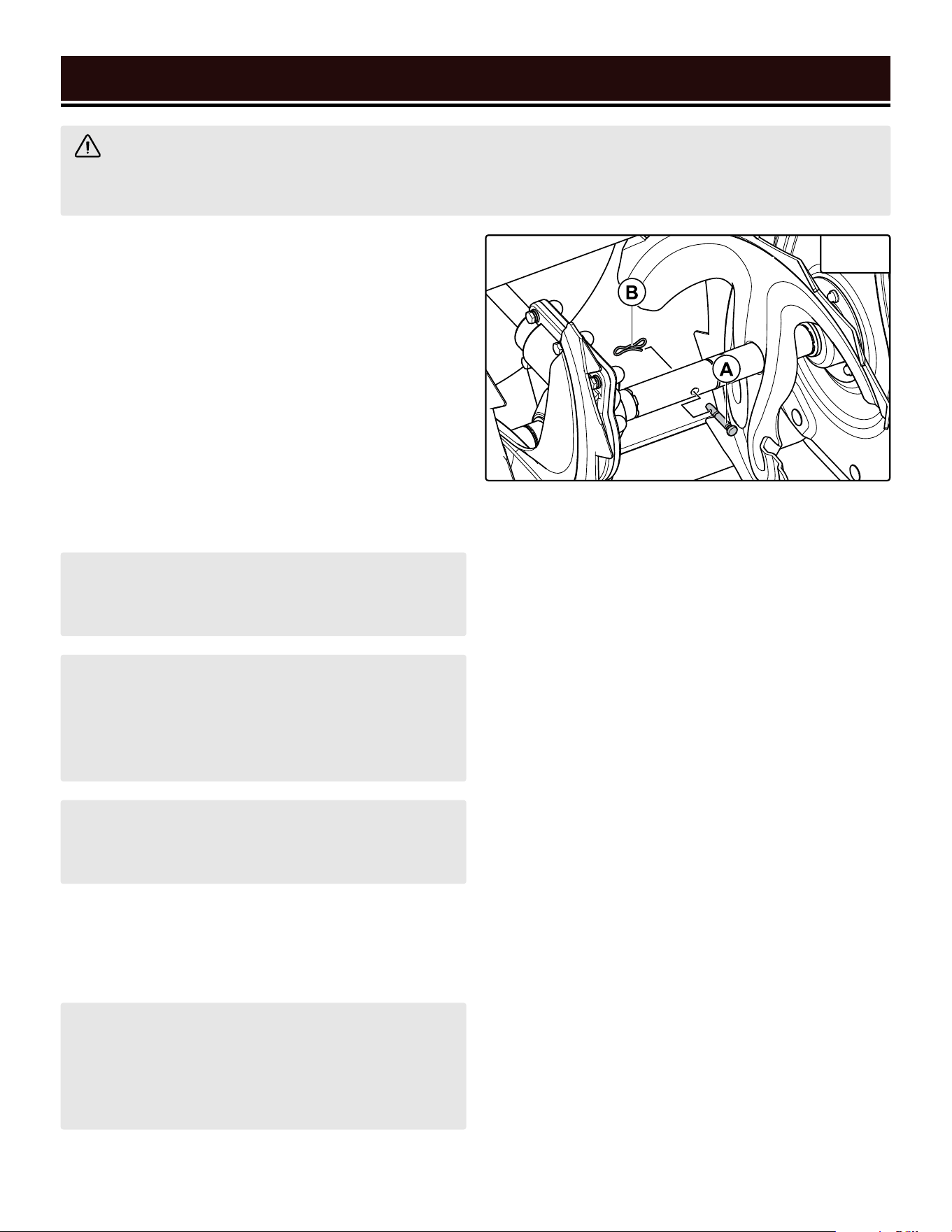
REPLACING SHEAR PINS (FIG. 27)
If a shear pin fails, it has done its job in protecting the
product from damage. Replacement shear pins and
bowtie clips can be ordered from wenproducts.com
(Part No's. SB24E-0208 and SB24E-0209, respective-
ly). Shear pins and bowtie clips are not covered under
the warranty.
To replace the the shear pins, stop the engine and wait
for the auger blades to come to a complete stop. In-
stall a new shear pin (A) and bowtie clip (B). Your snow
blower comes with two spare shear pins and two spare
bowtie clips.
SCRAPER BAR MAINTENANCE
Check the scraper bar (see page 11) for excess wear - if
it has begun to exhibit signs of severe wear, it is time
to replace it. Replacement scraper bars can be ordered
from wenproducts.com (Part No. SB24E-0329). Scrap-
er bars are a wear-out part and are not covered under
the warranty.
To replace the scraper bar, remove the four nuts and
bolts that secure the scraper bar to the auger housing.
Install the new scraper bar and replace the nuts and
bolts. Securely tighten the nuts.
WARNING! Over-inflating a tire could cause it to
burst, causing severe injury. DO NOT INFLATE TIRE
PAST 24 PSI.
CAUTION! When storing your snow blower for the
season, decrease tire pressure to 20 PSI. As spring
arrives, the air in your tires will warm up and expand,
raising the internal tire pressure. If the tire pressure
is not lowered, they could burst.
CAUTION! NEVER use an open flame (such as a
lighter, blowtorch, or flamethrower) to melt snow or
ice. Bring the snow blower to a heated area and let
the snow or ice melt on its own, or use a hairdryer
or heat gun.
NOTE: The tires are tubeless. If the air pressure is
allowed to drop too low, the tire may come off the
rim and need to be re-beaded.
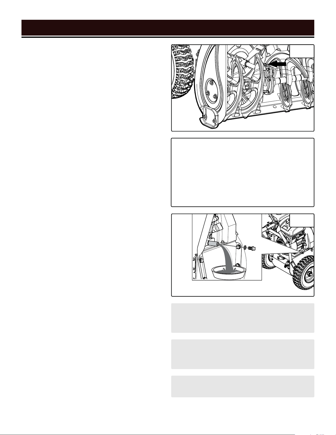
IMPELLER & AUGER MAINTENANCE
Check the impeller and auger for snow, ice, and debris
before and after use. Remove any snow, ice or debris
before storing the snow blower, or starting it.
Fig. 27
MAINTENANCE
25
ADJUSTING CABLE TENSION (FIG. 28)
Over time, the auger and drive engagement cables may
lengthen. To adjust cable tension, adjust the brass lock-
ing nut (C) and then adjust the cable bottle screw (D).
SNOW BLOWER BODY MAINTENANCE
Keep the body of the snow blower clean to prevent im-
proper operation or machine damage from dirt & de-
bris. Inspect all ventilation openings on the snow blow-
er. These must be kept clean and unobstructed.
Wipe down the snow blower’s housing with a damp
cloth and mild detergent. Dry it with a towel.
NOTE: Do not clean the snow blower with water
alone – it will freeze in low temperatures and cause
machine damage. Do not allow soap or water into
the inside of your snow blower.
Fig. 28
Fig. 29
DRIVE BELT MAINTENANCE
Periodically inspect the drive belts according to the
Recommended Maintenance Schedule on page 23.
Remove the two bolts (Fig. 29) that secure the belt cov-
er to the impeller housing. Check the belts for wear and
tear. If they are worn, frayed, stiff, or broken, they will
need to be replaced.
Replacement belts can be ordered at wenproducts.com
(Part No's. SB24E-0324 & SB24E-0606). Belts should
be replaced by an authorized service center. Contact
customer service at 1-800-232-1195, M – F, 8 – 5 CST,
the authorized service center nearest you.
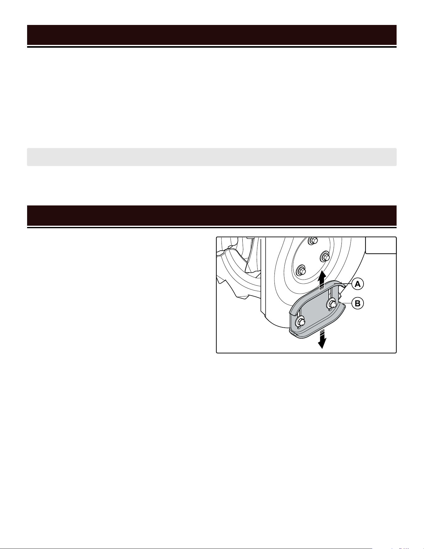
SKID PLATE MAINTENANCE
Check the skid plates for excess wear - if they have
begun to exhibit signs of severe wear, it is time to
replace them. Replacement skid plates can be ordered
from wenproducts.com (Part No. SB24E-0303). Skid
plates are a wear-out part and are not covered under
the warranty.
To replace a skid plate, remove the two nuts and bolts
that secure the skid plate to the auger housing. Install
the new skid plate and replace the nuts and bolts. Se-
curely tighten the nuts.
FRICTION DISC REPLACEMENT
After a long time (>100 hours), the friction disc may
require replacement. The interval of replacement
depends on how hard the machine was run, climate,
etc. Replacement friction discs can be ordered at
wenproducts.com (Part No. SB24E-0508). Friction
discs should be replaced by an authorized service
center. Contact customer service at 1-800-232-1195,
M – F, 8 – 5 CST, or [email protected]
for the location of the authorized service center nearest
you.
MAINTENANCE
26
AUGER GEARBOX LUBRICATION
Lubricate the gearbox according to the Recommended
Maintenance Schedule on page 23. Use a grease gun
to apply 1.25 – 2 oz (35 – 55 g) of extreme-pressure,
NLGI grade 3, automotive bearing or chassis grease to
the grease fitting on the auger gearbox (Fig. 30). The
bearings on your snow blower are permanently lubri-
cated and require no additional lubrication.
CHECKING & CHANGING OIL
Check the oil according to the Recommended Mainte-
nance Schedule on page 23. The oil capacity of the
engine is 20.3 fl. oz. (0.6 L). Add oil when the oil level is
low. For the proper type and weight of oil refer to page
15. This is a critical step for proper engine starting. To
check the oil level and/or add oil, see "Step 1 - Add/
Check Oil (Fig. 10 & Fig. 11)" on page 15.
To change the oil:
1. Run the engine for a few minutes to warm the oil up.
Warm oil flows more easily.
2. Prepare an approved oil-storage container under-
neath the oil drain bolt (Fig. 31). NOTE: to avoid spills
from the carburetor bowl, drain the carburetor (refer
to "Draining The Carburetor" on page 2227) before
draining the oil.
3. Unscrew the oil drain bolt and allow oil to drain from
the engine completely.
4. Reinstall the oil drain bolt and tighten it securely.
Wipe clean any oil spillage.
5. To add new oil, see "Step 1 - Add/Check Oil (Fig. 10 &
Fig. 11)" on page 15.
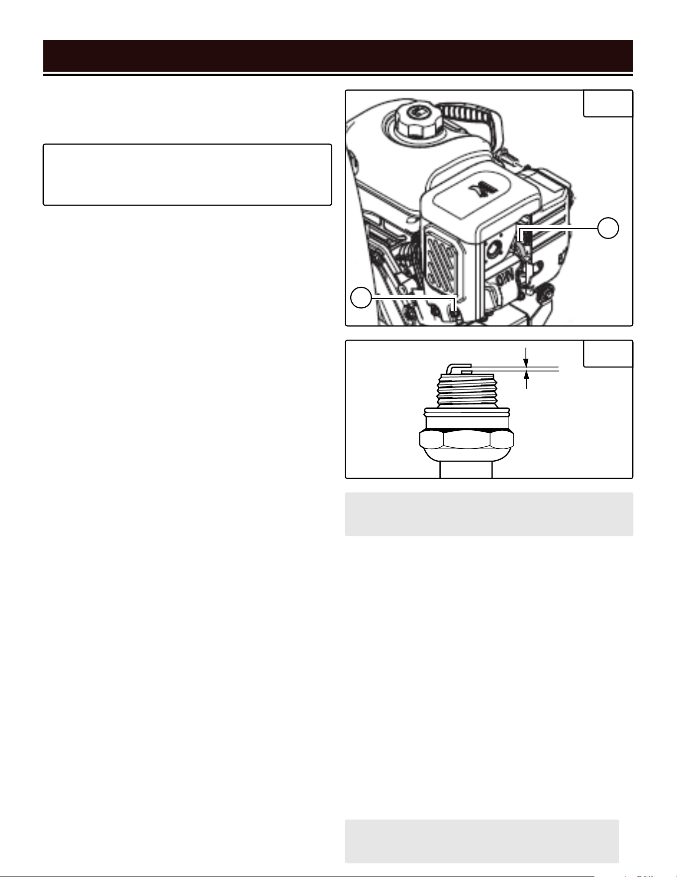
SPARK PLUG MAINTENANCE
Inspect and change the spark plug every 100 hours
of operation (refer to the Recommended Maintenance
Schedule on page 23). The spark plug is important for
proper engine operation. Check the spark plug regularly
to maintain proper engine operation. A good spark plug
should be intact, free of deposits, and properly gapped.
1. Gently pull on the spark plug boot (Fig. 32 - B) to
remove it. Be careful not to tear insulation or wire.
NOTE: Never dispose of used engine oil in the trash
or down a drain. Please call a local recycling center
or auto garage to arrange proper oil disposal.
CAUTION! Never run the engine with low oil, or with
no oil. Doing so will permanently damage the engine
and void the warranty.
CAUTION! Let the muffler cool down completely be-
fore performing spark plug maintenance.
TIP: Your WEN snow blower is compatible with the
WEN 55201 Magnetic Oil Dipstick (not included),
available for purchase at wenproducts.com. The
dipstick’s industrial-strength magnetic tip will col-
lect metal shavings from your snow blower’s oil
tank to help preserve the engine and extend your
snow blower’s lifespan. Remove the oil plug & in-
stall the Magnetic Oil Dipstick.
Fig. 30
Fig. 31
MAINTENANCE
27
2. Use the included spark plug wrench and handle to
unscrew the spark plug from the engine. Remove the
spark plug from the engine.
NOTE: Make sure to drain your carburetor before
storing the snow blower for long periods of time.
CAUTION! Store the emptied gasoline in a suitable
place. Never store fuel for more than 2 months.
TIP: There is limited space for the wrench to turn.
Use both rows of holes in the spark plug wrench to
gain leverage to loosen the plug.
Fig. 32
Fig. 33
3. Visually inspect the spark plug. If it is cracked or
chipped, or if the electrodes are worn or burned, discard
it and replace with a new spark plug. We recommend
replacing it with a Torch F7RTC/NGK BPR7ES spark
plug. These can be purchased from wenproducts.com
by searching part number SB24E-2008.
4. If re-using the spark plug, use a wire brush to clean
any dirt from around the spark plug base, then re-gap
the spark plug.
5. Measure the plug gap with a spark plug gap gauge.
The gap should be 0.7 to 0.8 mm (0.028-0.031 in).
Carefully adjust the gap if necessary. See Fig. 33.
6. Screw the spark plug back into the spark plug hole
using the spark plug wrench. Do not over-tighten spark
plug. Recommended tightening of the spark plug is ½
to ¾ of a turn after the spark plug gasket contacts the
spark plug hole, or 18.5 – 22 ft-lb torque (25 – 30 Nm).
7. Reinstall the spark plug boot over the spark plug.
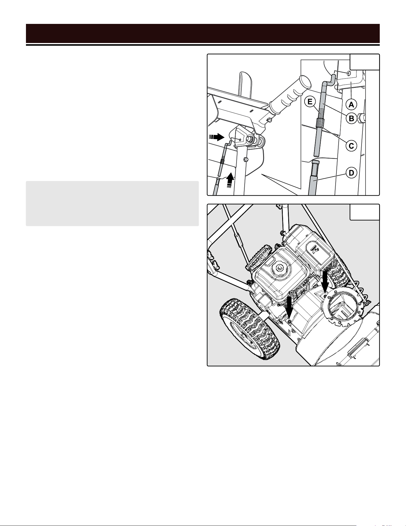
DRAINING THE CARBURETOR
Drain the carburetor after every use and before storing
the snow blower (refer to the Recommended Mainte-
nance Schedule on page 23). Draining the carburetor
can help prevent build-up and blockages caused by
stagnant fuel inside of the carburetor.
1. Prepare an approved gasoline-storage container un-
der the carburetor to collect the drained fuel. Make sure
the fuel valve is turned OFF.
2. The carburetor can be accessed from the left side
of the snow blower, next to the cylinder head cover. To
drain the carburetor, open up the carburetor drain screw
(Fig. 32 - A) with a Phillips-head screwdriver and drain
out any gasoline that has built up inside.
3. Once the fuel has drained, close the drain screw.
A
B
DRAINING THE FUEL TANK
Drain and clean the fuel tank each year, or before storing
the snow blower for longer than two months.
1. Prepare an approved gasoline-storage container un-
der the carburetor. Make sure the fuel valve is turned
OFF.
2. Remove the carburetor drain screw. Set it aside.
3. Turn the fuel valve to ON and let the fuel tank drain
completely This may take a while, depending on how
much gasoline remains in the tank.
4. Once the fuel has drained, replace the drain screw
and turn the fuel valve OFF.
5. Start and run the engine until the fuel runs out. Then,
drain the carburetor.

2828
MAINTENANCE
28
TRANSPORTATION & STORAGE
For transportation information, see "Transporting" on page 9.
WARNING! Avoid direct sunlight inside a vehicle. If the snow blower is left in an enclosed vehicle for many
hours, the high temperature could cause the fuel to vaporize and result in a possible explosion.
WARNING! Store the snow blower upright in a cool and dry location, away from sources of heat, open flames,
sparks or pilot lights.
Shut off the snow blower and allow the unit to cool to room temperature before storing it. NEVER place any type of
storage cover on the snow blower while it is still hot. Do not obstruct any ventilation openings.
Follow the procedures below for properly storing your snow blower. We highly recommend running your snow
blower once a month for 20 to 30 minutes, to ensure it is ready when you need it.
For Short Periods (30 to 60 Days):
• Drain the carburetor. Refer to "Draining The Carburetor" on
page 27.
• Add fuel stabilizer: Follow the suggested portions and
instructions of your preferred stabilizer. Run the engine for
15 to 20 minutes, allowing the fuel stabilizer to mix with the
gasoline and circulate through the carburetor, and then top
off with fuel. Filling the fuel tank full reduces the amount of
air in the tank and helps fight deterioration of fuel.
For Extended Periods (Over 60 Days):
• Drain the fuel tank and carburetor.
Refer to "Draining The Fuel Tank" and
"Draining The Carburetor" on page 27.
• Never store snow blower with fuel in
the tank for more than two months.
• Change the engine oil. Refer to
"Checking & Changing Oil" on page
26.
PRODUCT DISPOSAL
Do not dispose of used snow blower or parts with your household waste. This product contains electrical or elec-
tronic components that should be recycled. Please take this product to your local recycling facility for responsible
disposal to minimize its environmental impact.
Do not dispose of used oil or fuel in the trash or down a drain. Please contact your local recycling center or auto
garage to arrange proper oil/fuel disposal.
Please recycle the packaging and electronic components where facilities exist.

TROUBLESHOOTING GUIDE
292929
PROBLEM POSSIBLE CAUSE SOLUTION
Engine idles roughly or runs
roughly.
1. Choke improperly adjusted. 1. Adjust choke.
2. Fuel line blocked. 2. Clean fuel line.
3. Engine is filled with
contaminated or old fuel.
3. Drain fuel tank and carburetor. Replace with fresh
gasoline (87 octane, 10% ethanol maximum).
4. Bad carburetor.
4. Contact customer service at 1-800-232-1195
M – F 8 – 5 CST for assistance.
Excessive vibration.
1. Loose/damaged augers or
loose part.
1. Tighten all fasteners. Check that auger shear pins
are intact. Replace shear pins if needed.
2. Engine adjustment problem.
2. Contact customer service at 1-800-232-1195
M – F 8 – 5 CST for assistance.
Loss of drive traction, or
slowing of drive speed.
1. Wheel V-belt is worn, is
slipping, or is off the pulley.
1. Check V-belt. Contact customer service at
1-800-232-1195 M – F 8 – 5 CST for assistance.
2. Wheel(s) deflated. 2. Check wheel pressure. Adjust if necessary.
3. Worn friction disc.
3. Contact customer service at 1-800-232-1195
M – F 8 – 5 CST for assistance.
Loss of snow discharge, or
slowing of snow discharge.
1. Chute deflector or chute is
clogged.
1. Shut off engine and clear clog.
2. Auger is blocked. 2. Shut off engine and clear blockage.
3. Broken shear pin. 3. Replace shear pin.
4. Worn friction disc.
4. Contact customer service at 1-800-232-1195
M – F 8 – 5 CST for assistance.
Chute difficult to move.
1. Snow or ice is blocking chute
rotation.
1. Clear snow or ice.
2. Mounting nuts too tight. 2. Loosen mounting nuts.
Product turns to one side or
leans to one side.
1. Uneven tire pressure.
1. Check tire pressure on both sides and adjust tire
pressure until they are equal.
2. Tire lock pin disengaged from
wheel axle on one side.
2. Ensure both tire lock pins go through the tires
and the wheel axle.
3. Uneven skid plate adjustment. 3. Adjust skid plates height.
WARNING! Stop using the tool immediately if any of the following problems occur. Repairs and replacements
should only be performed by an authorized technician. For any questions, please contact our customer service
at (800) 232-1195, M-F 8-5 CST or email us at [email protected].
Troubleshooting guide continues on the next page.

TROUBLESHOOTING GUIDE
30
PROBLEM POSSIBLE CAUSE SOLUTION
Engine will not start.
1. Engine key not inserted. 1. Insert engine key fully.
2. Not enough gasoline in tank. 2. Fill tank.
3. Fuel valve is OFF. 3. Turn fuel valve to ON.
4. Choke is set to OPEN / RUN
(cold engine).
4. Set choke to CLOSED / START.
5. Choke is set to CLOSED /
START (warm engine).
5. Set choke to OPEN / RUN.
6. Primer bulb was not pushed. 6. Push primer bulb.
7. Engine is flooded.
7. Wait 5 minutes. DO NOT prime engine. Restart
engine with choke in CLOSED / START position.
8. Engine is filled with
contaminated or old fuel.
8. Drain fuel tank and carburetor. Replace with fresh
gasoline (87 octane, 10% ethanol maximum).
9. Carburetor is air-locked.
9. Turn fuel valve to OFF. Remove bolt from bottom
of carburetor. Remove carburetor bowl and allow
float to reset. Replace bowl and re-install bolt.
10. Spark plug boot
disconnected.
10. Connect spark plug boot to spark plug.
11. Spark plug dirty or broken. 11. Examine spark plug. Clean or replace as needed.
12. Electric start: power cord not
connected.
12. Connect power cord.
13. Electric start: no line voltage. 13. Check line voltage at power source.
14. Electric start: power cord
gauge too low or power cord
too long.
14. Refer to chart on p. 9 for recommended power
cord length and gauge.
15. Faulty ignition coil.
15. Contact customer service at 1-800-232-1195
M – F 8 – 5 CST for assistance.
16. Electric start: faulty starter
motor or control box.
16. Contact customer service at 1-800-232-1195
M – F 8 – 5 CST for assistance.
Decreased power.
1. Too much snow being blown.
1. Decrease forward speed. Blow a narrower path
through the snow.
2. Fuel tank cap covered in snow
or ice.
2. Clean fuel tank cap.
3. Muffler dirty or clogged.
3. Shut off engine and wait for it to cool down.
Clean muffler.
4. Improper cable length. 4. Adjust cable length or replace cable.
5. Carburetor air intake is
blocked.
5. Check and clear carburetor.

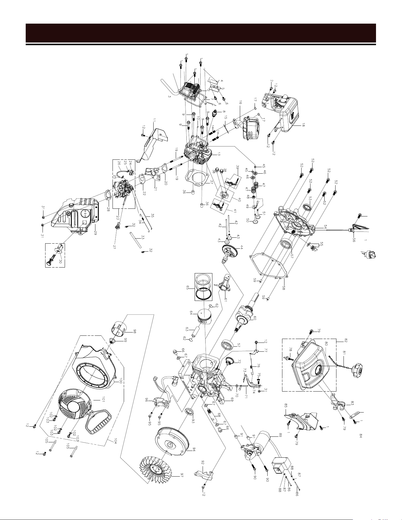
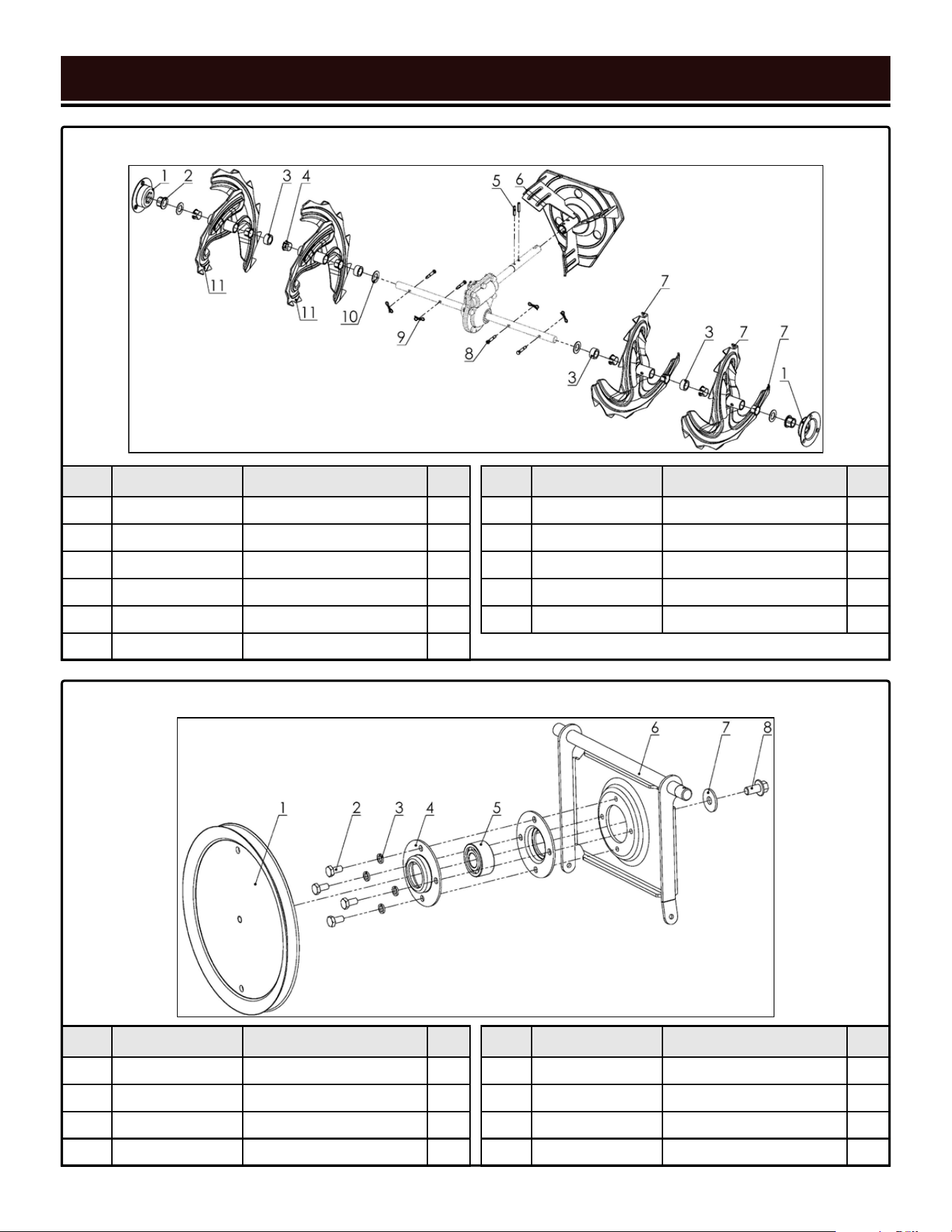
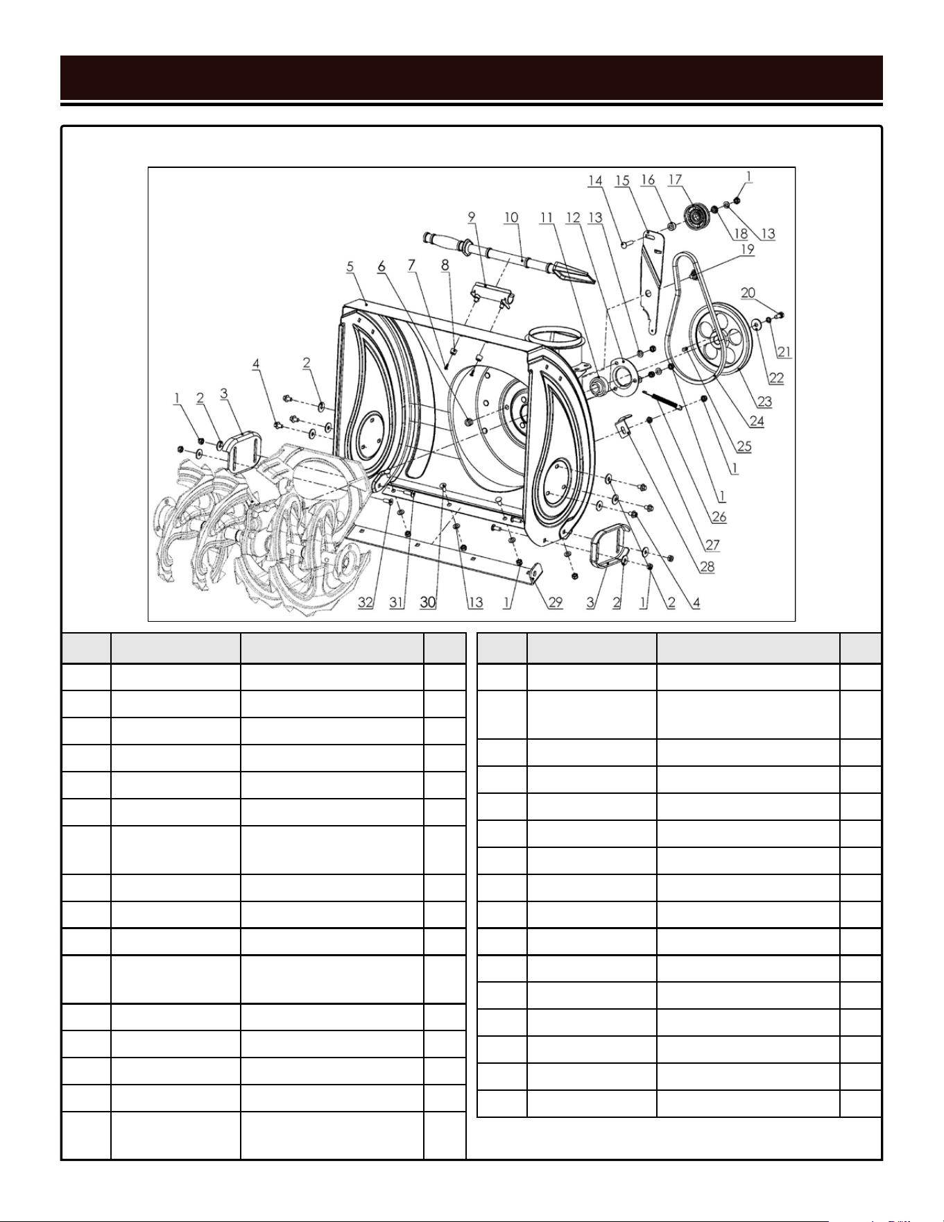
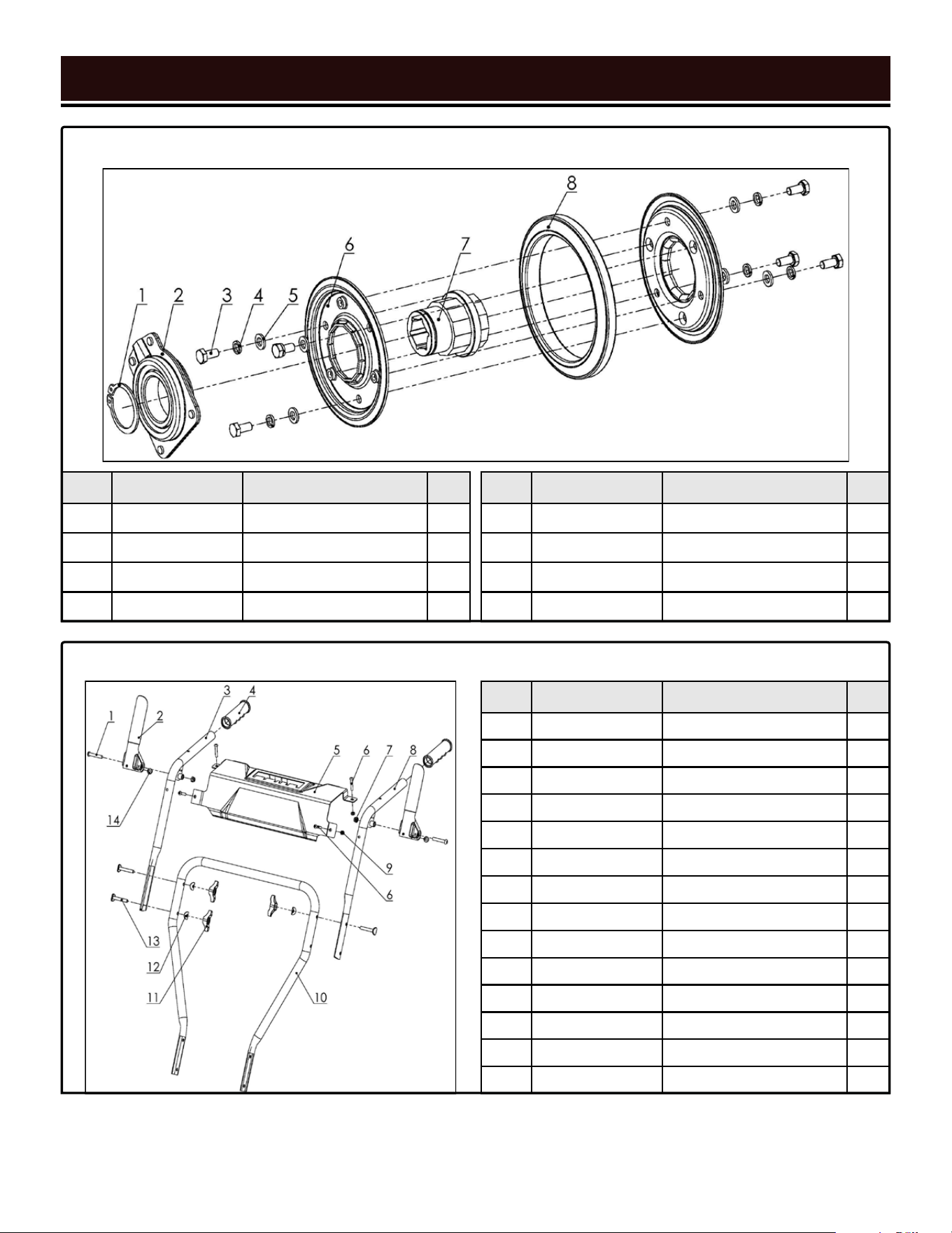
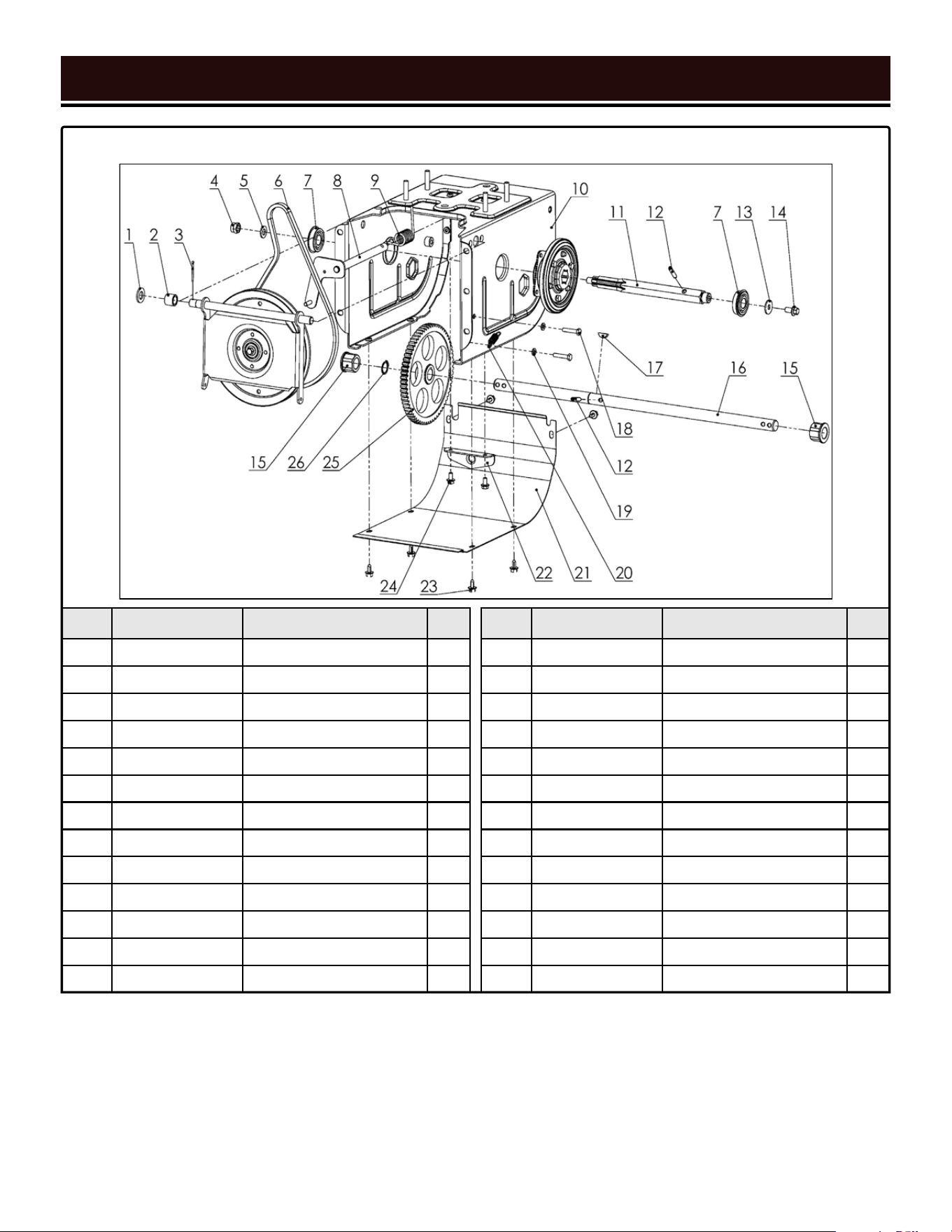
EXPLODED VIEW & PARTS LIST
3131
ENGINE PARTS LIST
No. Part No. Description Qty.
1 SB24E-2001 Flange Bolt, M6x20 8
2 SB24E-2002 Cylinder Head Cover 1
3 SB24E-2003 Breather Tube 1
4 SB24E-2004 Gasket, Breather Valve 1
5 SB24E-2005 Breather Valve 1
6 SB24E-2006 Hex Bolt, M5x8 2
7 SB24E-2007
Gasket, Cylinder Head
Cover
1
8 SB24E-2008
Spark Plug (Torch F7RTC/
NGK BPR7ES)
1
9 SB24E-2009 Flange Bolt, M8x60 4
10 SB24E-2010 Pin, 4mm x 8mm 1
11 SB24E-2011 Shroud 1
12 SB24E-2012 Flange Bolt, M6x12 8
13 SB24E-2013 Cylinder Head 1
14 SB24E-2014 Stud Bolt, M8x34 2
15 SB24E-2015 Gasket, Muffler 1
16 SB24E-2016 Muffler 1
17 SB24E-2017 Flange Nut, M8 2
18 SB24E-2018 Muffler Cover 1
19 SB24E-2019 Stud Bolt, M6x96 2
20 SB24E-2020 Gasket, Insulator 1
21 SB24E-2021 Insulator 1
22 SB24E-2022 Gasket, Carburetor 1
23 SB24E-2023 Carburetor Assembly 1
24 SB24E-2024 Primer Bulb 1
25 SB24E-2025 Tube Clip, 6.5mm 2
26 SB24E-2026 Primer Hose 1
27 SB24E-2027 Choke Lever 1
28 SB24E-2028 Gasket, Carburetor Cover 1
29 SB24E-2029 Air Filter 1
30 SB24E-2030 Engine Switch Assembly 1
31 SB24E-2031 Flange Nut, M6 3
No. Part No. Description Qty.
32 SB24E-2032 Tube Clip, 8.5mm 2
33 SB24E-2033 Fuel Tube 1
34 SB24E-2034 Governor Rod Spring 1
35 SB24E-2035 Governor Rod 1
36 SB24E-2036 Dowel Pin, 10mm x 16mm 2
37 SB24E-2037 Gasket, Cylinder Head 1
38 SB24E-2038 Flange Bolt, M8x32 2
39 SB24E-2039
Rocker Arm Assembly,
Exhaust
1
40 SB24E-2040 Rocker Arm Mount 1
41 SB24E-2041
Rocker Arm Assembly,
Intake
1
42 SB24E-2042 Push Rod 2
43 SB24E-2043 Valve Lifter 2
44 SB24E-2044 Camshaft Assembly 1
45 SB24E-2045 Valve Adjustment Nut 2
46 SB24E-2046 Valve Spring Retainer 2
47 SB24E-2047 Valve Spring 2
48 SB24E-2048 Valve Stem Seal 1
49 SB24E-2049 Guide Plate 1
50 SB24E-2050 Intake Valve 1
51 SB24E-2051 Exhaust Valve 1
52 SB24E-2052 Flange Bolt, M8x32 6
53 SB24E-2053 Oil Seal 1
54 SB24E-2054 Crankcase Cover 1
55 SB24E-2055 Oil Cap Assembly 1
56 SB24E-2056 Oil Dipstick Assembly 1
57 SB24E-2057 Ball Bearing, 6205 2
58 SB24E-2058 Gasket, Crankcase Cover 1
59 SB24E-2059 Dowel Pin, 8mm x 12mm 2
60 SB24E-2060 Crankshaft Assembly 1
61 SB24E-2061 Connecting Rod Assembly 1
62 SB24E-2062 Piston Pin Clip 2
NOTE: Replacement parts can be purchased from wenproducts.com, or by calling our customer service at
(800) 232-1195, M-F 8-5 CST. Parts and accessories that wear down over the course of normal use are not
covered by the two-year warranty.

EXPLODED VIEW & PARTS LIST
32
No. Part No. Description Qty.
63 SB24E-2063 Piston Pin 1
64 SB24E-2064 Piston 1
65 SB24E-2065 Piston Ring Set 1
66 SB24E-2066 Drain Bolt, M10x15 2
67 SB24E-2067 Flat Washer, 10mm 3
68 SB24E-2068 Drain Extension Tube 1
69 SB24E-2069 Crankcase 1
70 SB24E-2070 Flat Washer, 6mm 1
71 SB24E-2071 Governor Shaft 1
72 SB24E-2072 Governor Gear Assembly 1
73 SB24E-2073 Locking Pin 1
74 SB24E-2074 Governor Arm 1
75 SB24E-2075 T-Bolt, M6x20 1
76 SB24E-2076 Governor Arm Spring 1
77 SB24E-2077 Control Bracket Assembly 1
78 SB24E-2078 Fuel Tank Filter 1
79 SB24E-2079 Flange Bolt, M6x16 3
80 SB24E-2080 Fuel Tank 1
81 SB24E-2081 Fuel Tank Cap Assembly 1
82 SB24E-2082 Fuel Tank Assembly 1
83 SB24E-2083
Control Box Mounting
Bracket
1
84 SB24E-2084 Clip 1
85 SB24E-2085 Engine Cover 1
86 SB24E-2086 Screw, M4x55 2
87 SB24E-2087 Spring Washer, 4mm 2
88 SB24E-2088 Flat Washer, 4mm 1
89 SB24E-2089 Starter Motor 1
90 SB24E-2090 Flange Bolt, M6x30 2
91 SB24E-2091 Dowel Pin, 8mm x 10mm 2
92 SB24E-2092 Shroud 1
93 SB24E-2093 Oil Seal 1
94 SB24E-2094 Flywheel 1
95 SB24E-2095 Flange Bolt, M6x22 2
96 SB24E-2096 Ignition Coil 1
97 SB24E-2097 Fan 1
No. Part No. Description Qty.
98 SB24E-2098 Starter Pulley 1
99 SB24E-2099 Flange Nut, M14-1.5 1
100 SB24E-2100 Recoil Starter Housing 1
101 SB24E-2101 Recoil Starter 1
102 SB24E-2102 Flat Washer, 6mm 1
103 SB24E-2103 Flange Bolt, M6x8 1
104 SB24E-2104
Recoil Starter
Subassembly
1
105 SB24E-2105 Double-Flange Bolt, M6x12 2
ENGINE PARTS LIST - CONTINUED
EXPLODED VIEW & PARTS LIST
33
ENGINE EXPLODED VIEW
No. Part No. Description Qty.
1-1 SB24E-0101 Bolt, M6x20 6
1-2 SB24E-0102 Bolt, M6x25 1
1-3 SB24E-0103 Spring Washer, 6mm 7
1-4 SB24E-0104 Flat Washer, 6mm 7
1-5 SB24E-0105 Washer, 10mm 1
1-6 SB24E-0106 Grease Fitting, M10-1.0 1
1-7 SB24E-0107 Ball Bearing, 61904-2Z 1
1-8 SB24E-0108 Flat Washer, 20mm 1
1-9 SB24E-0109 Bearing, 51104 1
1-10 SB24E-0110 Oil Seal 1
No. Part No. Description Qty.
1-11 SB24E-0111 Worm Gearshaft 1
1-12 SB24E-0112 Ball Bearing, 16001-2Z 1
1-13 SB24E-0113 Worm Gear 1
1-14 SB24E-0114 Oil Seal 2
1-15 SB24E-0115 Left Housing 1
1-16 SB24E-0116 Woodruff Key 1
1-17 SB24E-0117 Auger Shaft 1
1-18 SB24E-0118 Right Housing 1
1-19 SB24E-0119 Bolt, M5x8 1
EXPLODED VIEW & PARTS LIST
34
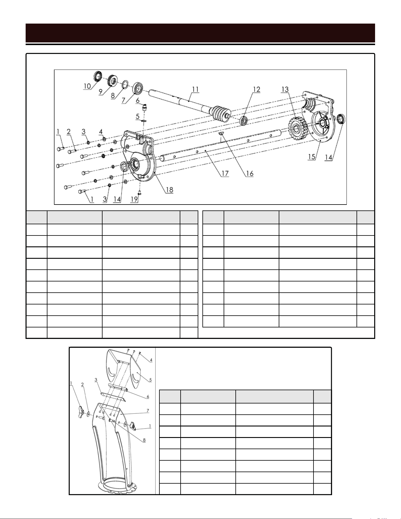
ASSEMBLY 1 - WORM HOUSING
No. Part No. Description Qty.
2-1 SB24E-0711 Knob 2
2-2 SB24E-0302 Flat Washer, 8mm 2
2-3 SB24E-1203 Chute Hinge Gasket 1
2-4 SB24E-1204 Bolt, M4x12 7
2-5 SB24E-1205 Chute Deflector Plate 1
2-6 SB24E-1206 Hinge 1
2-7 SB24E-1207 Chute 1
2-8 SB24E-1208 Bolt, M8x25 2
ASSEMBLY 2 - CHUTE
No. Part No. Description Qty.
3-1 SB24E-0201 Shaft Cover 2
3-2 SB24E-0202 Shaft Bushing 2
3-3 SB24E-0203 Fixed Bushing 4
3-4 SB24E-0204 Adjustsble Bushing 8
3-5 SB24E-0205 Pin, 6mm x 35mm 2
3-6 SB24E-0206 Impeller 1
No. Part No. Description Qty.
3-7 SB24E-0207 Left Auger 2
3-8 SB24E-0208 Shear Pin 4
3-9 SB24E-0209 Bowtie Clip 4
3-10 SB24E-0210 Flat Washer, 19.5mm 4
3-11 SB24E-0211 Right Auger 2
EXPLODED VIEW & PARTS LIST
35
ASSEMBLY 3 - AUGER
No. Part No. Description Qty.
4-1 SB24E-0401 Driven Pulley 1
4-2 SB24E-0402 Bolt, M6x12 4
4-3 SB24E-0403 Spring Washer, 6mm 4
4-4 SB24E-0404 Driven Pulley Bearing Seat 2
No. Part No. Description Qty.
4-5 SB24E-0405 Bearing, 3202-2RS 1
4-6 SB24E-0406 Driven Pulley Bracket 1
4-7 SB24E-0302 Flat Washer, 8mm 1
4-8 SB24E-0408 Bolt, M8x16 1
ASSEMBLY 4 - DRIVE PULLEY
EXPLODED VIEW & PARTS LIST
36
No. Part No. Description Qty.
5-1 SB24E-0301 Nut, M8 13
5-2 SB24E-0302 Flat Washer, 8mm 10
5-3 SB24E-0303 Skid 2
5-4 SB24E-0304 Bolt, M8x12 6
5-5 SB24E-0305 Auger Housing 1
5-6 SB24E-0306 Nut, M10 1
5-7 SB24E-0307
Self-Tapping Screw,
ST4.2x12
2
5-8 SB24E-0308 Bushing 2
5-9 SB24E-0309 Shovel Bracket 1
5-10 SB24E-0310 Shovel 1
5-11 SB24E-0311
Radial-Insert Ball Bearing,
UC204
1
5-12 SB24E-0312 Bearing Seat 1
5-13 SB24E-0313 Flat Washer, 8mm 4
5-14 SB24E-0314 Bolt, M8x35 1
5-15 SB24E-0315 Belt Tensioner Bracket 1
5-16 SB24E-0316
Long Tension Pulley
Bushing
1
No. Part No. Description Qty.
5-17 SB24E-0317 Belt Tension Pulley 1
5-18 SB24E-0318
Short Tension Pulley
Bushing
1
5-19 SB24E-0319 Bolt, M10x14 1
5-20 SB24E-0320 Bolt, M8x20 1
5-21 SB24E-0321 Spring Washer, 8mm 1
5-22 SB24E-0322 Flat Washer, 8mm 1
5-23 SB24E-0323 Auger Pulley 1
5-24 SB24E-0324 Auger Belt (4LXA822E) 1
5-25 SB24E-0325 Key 1
5-26 SB24E-0326 Tension Pulley Spring 1
5-27 SB24E-0327 Nut, M8 1
5-28 SB24E-0328 Belt Tension Bracket 1
5-29 SB24E-0329 Scraper 1
5-30 SB24E-0330 Bolt, M8x16 4
5-31 SB24E-0331 Bolt, M8x25 2
5-32 SB24E-0332 Bolt, M8x20 2
ASSEMBLY 5 - AUGER HOUSING
EXPLODED VIEW & PARTS LIST
37
No. Part No. Description Qty.
6-1
SB24E-0501 Circlip 1
6-2
SB24E-0502 Shifting Fork Cover 1
6-3
SB24E-0503 Bolt, M6x12 6
6-4
SB24E-0504 Spring Washer, 6mm 6
No. Part No. Description Qty.
7-1 SB24E-0701 Bolt, M8x45 2
7-2 SB24E-0702 Clutch Lever 2
7-3 SB24E-0703 Right Handle 1
7-4 SB24E-0704 Grip 2
7-5 SB24E-0705B Panel 1
7-6 SB24E-0706 Bolt, M6x35 4
7-7 SB24E-0707 Nut, M8 2
7-8 SB24E-0708 Left Handle 1
7-9 SB24E-0709 Nut, M6 4
7-10 SB24E-0710 Lower Handle 1
7-11 SB24E-0711 Knob 3
7-12 SB24E-0712 Bent Washer, 8mm 3
7-13 SB24E-0713 Lock Bolt, M8x50 3
7-14 SB24E-0714 Clutch Lever Gasket 2
No. Part No. Description Qty.
6-5
SB24E-0505 Flat Washer, 6mm 6
6-6
SB24E-0506 Friction Disc Plate 2
6-7
SB24E-0507 Friction Disc Shaft Sleeve 1
6-8
SB24E-0508 Friction Disc 1
ASSEMBLY 6 - FRICTION DISK
ASSEMBLY 7 - HANDLE
No. Part No. Description Qty.
8-1 SB24E-0601 Flat Washer, 13.5mm 1
8-2 SB24E-0602 Bushing 1
8-3 SB24E-0603 Pin 1
8-4 SB24E-0604 Nut, M10 1
8-5 SB24E-0605 Flat Washer, 10mm 1
8-6 SB24E-0606 Wheel Belt (3LXA809) 1
8-7 SB24E-0607 Ball Bearing, 6203-2RS 2
8-8 SB24E-0608 Shifting Fork 1
8-9 SB24E-0609 Shifting Fork Spring 1
8-10 SB24E-0610 Wheel Housing 1
8-11 SB24E-0611 Friction Disc Shaft 1
8-12 SB24E-0612 Pin 2
8-13 SB24E-0302 Flat Washer, 8mm 1
No. Part No. Description Qty.
8-14 SB24E-0614 Bolt, M8x16 1
8-15 SB24E-0615 Shaft Bushing 2
8-16 SB24E-0616 Wheel Axle 1
8-17 SB24E-0617 Woodruff Key 1
8-18 SB24E-0618 Bolt, M6x30 2
8-19 SB24E-0619 Flat Washer, 6mm 2
8-20 SB24E-0620 Driven Pulley Spring 1
8-21 SB24E-0621 Wheel Housing Cover 1
8-22 SB24E-0622 Shifting Fork Bracket 1
8-23 SB24E-0623 Self-tapping Screw, M6x12 8
8-24 SB24E-0624 Bolt, M6x30 2
8-25 SB24E-0625 Driven Gear 1
8-26 SB24E-0626 Shaft Retainer Ring 1
ASSEMBLY 8 - WALKING CASE
EXPLODED VIEW & PARTS LIST
38
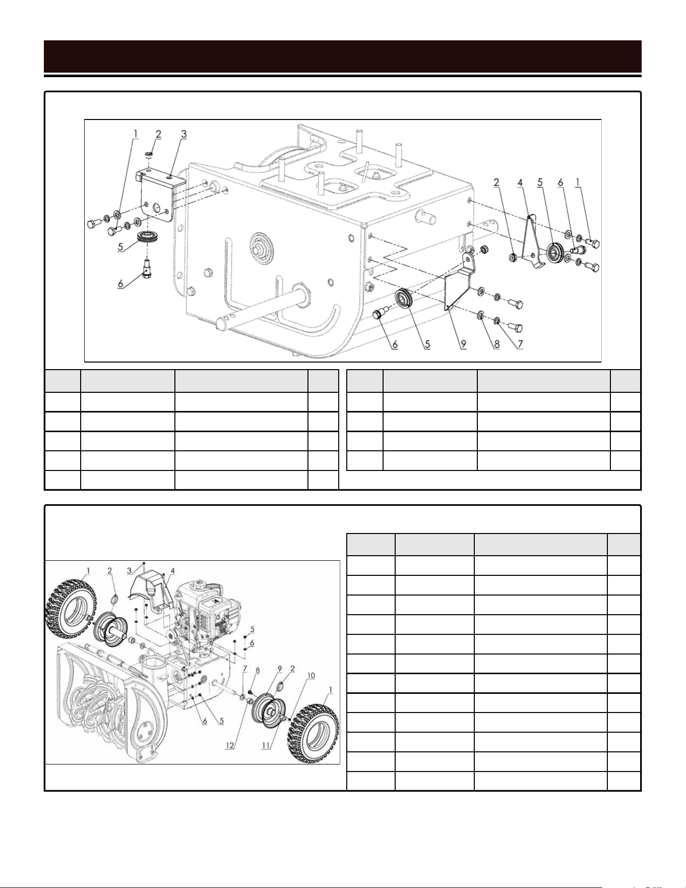
No. Part No. Description Qty.
9-1 SB24E-0801 Bolt, M6x16 6
9-2 SB24E-0802 Nut, M6 3
9-3 SB24E-0803 Rear Auger Cable Bracket 1
9-4 SB24E-0804 Wheel Cable Bracket 1
9-5 SB24E-0805 Cable Pulley 3
No. Part No. Description Qty.
9-6 SB24E-0806 Cable Pulley Shaft, M6x10 3
9-7 SB24E-0807 Spring Washer, 6mm 6
9-8 SB24E-0808 Flat Washer, 6mm 7
9-9 SB24E-0809 Front Auger Cable Bracket 1
ASSEMBLY 9 - CABLE BRACKET
EXPLODED VIEW & PARTS LIST
39
No. Part No. Description Qty.
10-1 SB24E-1101 Tire (13x4.10 - 6) 2
10-2 SB24E-1102 Wheel Pin 2
10-3 SB24E-1103 Bolt, M6x12 2
10-4 SB24E-1104 Belt Cover 1
10-5 SB24E-1105 Locking Nut, M8 7
10-6 SB24E-1106 Flat Washer, 8mm 10
10-7 SB24E-1107 Flat Washer, 19.5mm 2
10-8 SB24E-1108 Valve 2
10-9 SB24E-1109 Hub (13x4.1 - 6) 2
10-10 SB24E-1110 Valve Stem Cap 2
10-11 SB24E-1111 Axle Sleeve With Hole 2
10-12 SB24E-1112 Axle Sleeve Without Hole 2
ASSEMBLY 10 - WHEELS
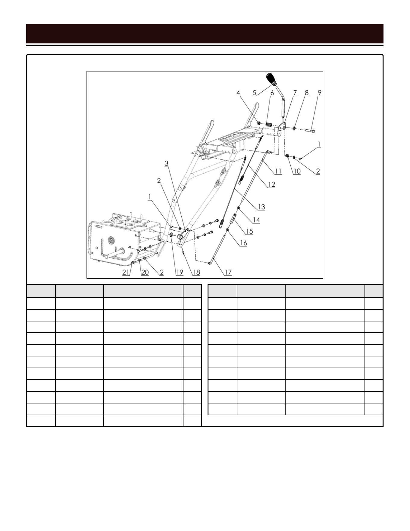
No. Part No. Description Qty.
11-1 SB24E-0901 Cotter Pin 2
11-2 SB24E-0902 Flat Washer, 8mm 6
11-3 SB24E-0903 Connecting Arm 1
11-4 SB24E-0904 Nut, M10 1
11-5 SB24E-0905 Shifting Lever 1
11-6 SB24E-0906 Shifting Bracket Spring 1
11-7 SB24E-0907 Shifting Bracket 1
11-8 SB24E-0908 Bushing 1
11-9 SB24E-0909 Bolt, M10x50 1
11-10 SB24E-0910 Shifting Spring 1
11-11 SB24E-0911 Upper Shifter Rod 1
No. Part No. Description Qty.
11-12 SB24E-0912 Wheel Clutch Cable 1
11-13 SB24E-0913 Auger Clutch Cable 1
11-14 SB24E-0914 Nut, M8 1
11-15 SB24E-0915 Shifter Rod Bottle Screw 1
11-16 SB24E-0916 Bolt, M8 1
11-17 SB24E-0917 Lower Shifter Rod 1
11-18 SB24E-0918 Pin 1
11-19 SB24E-0919 Flat Washer, 13.5mm 1
11-20 SB24E-0920 Spring Washer, 8mm 4
11-21 SB24E-0921 Bolt, M8x25 4
ASSEMBLY 11 - SHIFTING LEVER
EXPLODED VIEW & PARTS LIST
40
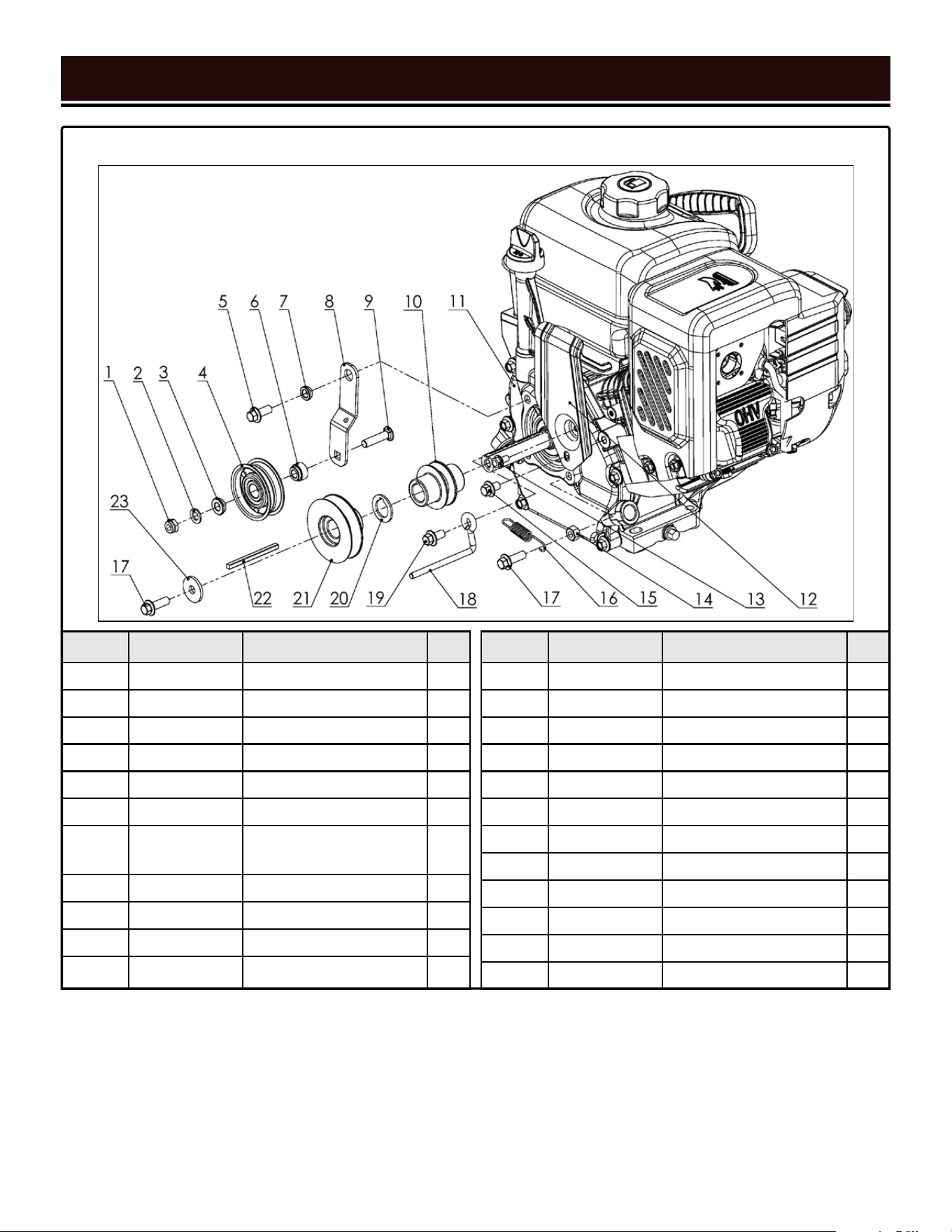
No. Part No. Description Qty.
12-1 SB24E-1001 Nut, M8 1
12-2 SB24E-1002 Flat Washer, 8mm 4
12-3 SB24E-1003 Tension Pulley Bushing 1
12-4 SB24E-1004 Tension Pulley 1
12-5 SB24E-1005 Bolt, M8x20 1
12-6 SB24E-1006 Tension Pulley Sleeve 1
12-7 SB24E-1007
Tension Pulley Bracket
Bushing
1
12-8 SB24E-1008 Tension Pulley Bracket 1
12-9 SB24E-1009 Bolt, M8x35 1
12-10 SB24E-1010 Driving Pulley, Wheels 1
12-11 SB24E-1011 Engine Assembly 1
No. Part No. Description Qty.
12-12 SB24E-1012 Shield 1
12-13 SB24E-1013 Bolt, M6x12 1
12-14 SB24E-1014 Nut, M8 1
12-15 SB24E-1015 Bolt, M8x12 1
12-16 SB24E-1016 Tension Pulley Spring 1
12-17 SB24E-1017 Bolt, M8x25 2
12-18 SB24E-1018 Belt Guide 1
12-19 SB24E-1019 Bolt, M8x16 1
12-20 SB24E-1020 Driving Pulley Washer 1
12-21 SB24E-1021 Driving Pulley, Auger 1
12-22 SB24E-1022 Key, 4.78x70mm 1
12-23 SB24E-1023 Flat Washer, 8mm 1
ASSEMBLY 12 - ENGINE BELT PULLEY
EXPLODED VIEW & PARTS LIST
41
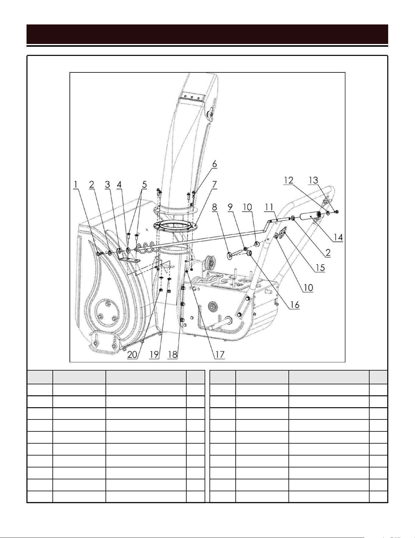
EXPLODED VIEW & PARTS LIST
42
No. Part No. Description Qty.
13-1 SB24E-1301 R-clip 1
13-2 SB24E-1302 Flat Washer, 10mm 2
13-3 SB24E-1303 Rotator Handle Bracket 1
13-4 SB24E-1304 Rotator Handle Seat 1
13-5 SB24E-1305 Bolt, M8x20 2
13-6 SB24E-1306 Bolt, M6x22 6
13-7 SB24E-1307 Chute Base Plate 1
13-8 SB24E-1308 Rotator Handle Eye Bolt 1
13-9 SB24E-1309 Nut. M8 1
13-10 SB24E-1310 Bent Washer, 8mm 2
ASSEMBLY 13 - CHUTE ROTATOR
No. Part No. Description Qty.
13-11 SB24E-1311 Rod 1
13-12 SB24E-1312 Flat Washer, M6 1
13-13 SB24E-1313 Bolt, M6x12 1
13-14 SB24E-1314 Rotator Handle Grip 1
13-15 SB24E-0711 Knob 1
13-16 SB24E-1316 Bushing 1
13-17 SB24E-1317 Nut, M6 6
13-18 SB24E-1318 Positioning Plate 3
13-19 SB24E-1319 Flat Washer, 8mm 12
13-20 SB24E-1320 Nut, M8 8

WARRANTY
43
WEN Products is committed to building tools that are dependable for years. Our warranties are consistent with this
commitment and our dedication to quality.
LIMITED WARRANTY OF WEN PRODUCTS FOR HOME USE
GREAT LAKES TECHNOLOGIES, LLC (“Seller”) warrants to the original purchaser only, that all WEN consumer power
tools will be free from defects in material or workmanship during personal use for a period of two (2) years from date
of purchase or 500 hours of use; whichever comes first. Ninety days for all WEN products if the tool is used for pro-
fessional or commercial use. Purchaser has 30 days from the date of purchase to report missing or damaged parts.
SELLER’S SOLE OBLIGATION AND YOUR EXCLUSIVE REMEDY under this Limited Warranty and, to the extent per-
mitted by law, any warranty or condition implied by law, shall be the replacement of parts, without charge, which are
defective in material or workmanship and which have not been subjected to misuse, alteration, careless handling,
misrepair, abuse, neglect, normal wear and tear, improper maintenance, improper storage, incorrect lubricants/fuels,
or other conditions adversely affecting the Product or the component of the Product, whether by accident or inten-
tionally, by persons other than Seller. To make a claim under this Limited Warranty, you must make sure to keep a
copy of your proof of purchase that clearly defines the Date of Purchase (month and year) and the Place of Purchase.
Place of Purchase must be a direct vendor of Great Lakes Technologies, LLC. Purchasing through third party vendors,
including but not limited to garage sales, pawn shops, resale shops, or any other secondhand merchant, voids the
warranty included with this product. Contact [email protected] or 1-800-232-1195 with the following
information to make arrangements: your shipping address, phone number, serial number, required part numbers,
and proof of purchase. Damaged or defective parts and products may need to be sent to WEN before the replace-
ments can be shipped out.
Upon the confirmation of a WEN representative, your product may qualify for repairs and service work. When re-
turning a product for warranty service, the shipping charges must be prepaid by the purchaser. The product must
be shipped in its original container (or an equivalent), properly packed to withstand the hazards of shipment. The
product must be fully insured with a copy of the proof of purchase enclosed. There must also be a description of the
problem in order to help our repairs department diagnose and fix the issue. Repairs will be made and the product
will be returned and shipped back to the purchaser at no charge for addresses within the contiguous United States.
THIS LIMITED WARRANTY DOES NOT APPLY TO ITEMS THAT WEAR OUT FROM REGULAR USAGE OVER TIME,
INCLUDING FILTERS, SPARK PLUGS, VOLTAGE REGULATORS, BRUSHES, GASKETS, O-RINGS, WHEEL KITS, BAT-
TERIES, RECOIL STARTERS, HIGH PRESSURE HOSES, SPRAY GUNS, ETC. ANY IMPLIED WARRANTIES SHALL BE
LIMITED IN DURATION TO TWO (2) YEARS FROM DATE OF PURCHASE. SOME STATES IN THE U.S. AND SOME
CANADIAN PROVINCES DO NOT ALLOW LIMITATIONS ON HOW LONG AN IMPLIED WARRANTY LASTS, SO THE
ABOVE LIMITATION MAY NOT APPLY TO YOU.
IN NO EVENT SHALL SELLER BE LIABLE FOR ANY INCIDENTAL OR CONSEQUENTIAL DAMAGES (INCLUDING BUT
NOT LIMITED TO LIABILITY FOR LOSS OF PROFITS) ARISING FROM THE SALE OR USE OF THIS PRODUCT. SOME
STATES IN THE U.S. AND SOME CANADIAN PROVINCES DO NOT ALLOW THE EXCLUSION OR LIMITATION OF IN-
CIDENTAL OR CONSEQUENTIAL DAMAGES, SO THE ABOVE LIMITATION OR EXCLUSION MAY NOT APPLY TO YOU.
THIS LIMITED WARRANTY GIVES YOU SPECIFIC LEGAL RIGHTS, AND YOU MAY ALSO HAVE OTHER RIGHTS
WHICH VARY FROM STATE TO STATE IN THE U.S., PROVINCE TO PROVINCE IN CANADA AND FROM COUNTRY TO
COUNTRY.
THIS LIMITED WARRANTY APPLIES ONLY TO ITEMS SOLD WITHIN THE UNITED STATES OF AMERICA, CANADA
AND THE COMMONWEALTH OF PUERTO RICO. FOR WARRANTY COVERAGE WITHIN OTHER COUNTRIES, CON-
TACT THE WEN CUSTOMER SUPPORT LINE. FOR WARRANTY PARTS OR PRODUCTS REPAIRED UNDER WARRAN-
TY SHIPPING TO ADDRESSES OUTSIDE OF THE CONTIGUOUS UNITED STATES, ADDITIONAL SHIPPING CHARGES
MAY APPLY.

V.2020.09.03
THANKS FOR
REMEMBERING
