
24-INCH TWO-STAGE
SNOW BLOWER
Instruction Manual
IMPORTANT: Your new tool has been engineered and manufactured to WEN’s highest standards for dependability,
ease of operation, and operator safety. When properly cared for, this product will supply you years of rugged,
trouble-free performance. Pay close attention to the rules for safe operation, warnings, and cautions. If you use
your tool properly and for its intended purpose, you will enjoy years of safe, reliable service.
NEED HELP? CONTACT US!
Have product questions? Need technical support? Please feel free to contact us:
TECHSUPPOR[email protected]1-847-429-9263 (M-F 8AM-5PM CST)
For replacement parts and the most up-to-date instruction manuals, visit WENPRODUCTS.COM
MODEL SB209E

CONTENTS
WELCOME 3
Specifications ....................................................................................................3
Introduction ......................................................................................................4
SAFETY 5
General Safety Rules .........................................................................................5
Snow Blower Safety Warnings ..........................................................................8
Electrical Information ......................................................................................11
BEFORE OPERATING 11
Unpacking & Packing List ...............................................................................11
Know Your Snow Blower.................................................................................13
Assembly & Adjustments ................................................................................14
Snow Blower Preparation ................................................................................18
OPERATION & MAINTENANCE 21
Starting Your Snow Blower .............................................................................21
Operation ........................................................................................................23
Maintenance ....................................................................................................25
Troubleshooting Guide ....................................................................................30
Exploded View & Parts List .............................................................................32
Warranty Statement ........................................................................................43
To purchase accessories and replacement parts for your tool, visit WENPRODUCTS.COM
Magnetic Oil Dipstick (Model 55201)
100-Foot Extension Cord (Model PC1123)
50-Foot Extension Cord (Model PC5124)
High-Altitude Kit (Part SB209E-HA36, SB209E-HA68)
2

SPECIFICATIONS
Model Number SB209E
Stages 2-Stage
Maximum Clearing Width 24 in.
Maximum Clearing Height 20 in.
Throwing Distance 30 feet
Auger Diameter 10 in.
Tires 13 in. x 4.1 in. tubeless
Speed Control 6 speeds forward, 2 speeds backwards
Chute Range of Motion 190 degrees
Weight 144 pounds
Product Dimensions 30.3 in. x 24.6 in. x 24.6 in.
Engine Type 4-stroke, OHV, single-cylinder with forced-air cooling system
Engine Displacement 209cc
Fuel Tank Capacity 0.6 gallons (2.3 L)
Oil Capacity 16.9 fl. oz (0.5 L)
Runtime up to 2 hours
Lubrication System Splash lubrication
Spark Plug Type Torch F6TC (NGK BP6ES)
Spark Plug Gap 0.7mm - 0.8mm (0.028 in. - 0.031 in.)
Spark Plug Torque 14.75 - 19.18 ft-lb (20 - 26 Nm)
Electric Start 120VAC, 10A, Onboard Receptacle
ENGINE
SNOW BLOWER
3
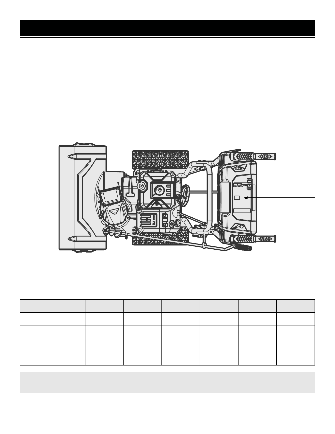
Thanks for purchasing the WEN snow blower. Refer to the illustration below for the location of the serial number on
the control panel label. Record the snow blower information in the spaces provided below. If assistance for informa-
tion or service is required, please contact customer service by calling 1-847-429-9263, M-F 8-5 CST; you will be
asked to provide the following snow blower information when calling.
Snow Blower Model Number: SB209E
Date of Purchase: _______________________________________________
Purchased From: ________________________________________________
Serial Number: _________________________________________________
TO MAXIMIZE THE LIFESPAN OF YOUR SNOW BLOWER: We recommend running your snow blower at least
once a month for 20 to 30 minutes. Start the snow blower according to the instructions.
SERVICE RECORD
Record the service dates of your snow blower in the chart below. Please perform maintenance checks and opera-
tions according to this manual. Refer to "MAINTENANCE" on page 26.
Service Record Date Date Date Date Date Date
Change Oil
Change Spark Plug
Drain Fuel Tank
Check Tires
INTRODUCTION
Serial Number
4

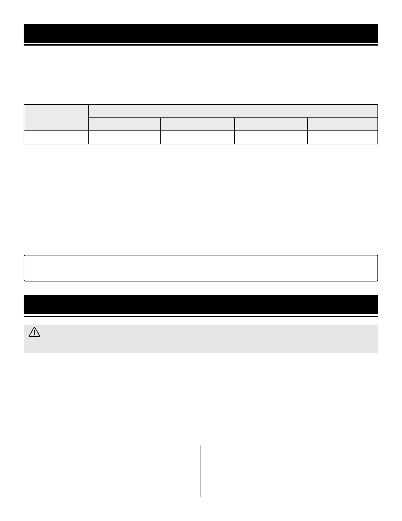
WARNING: Before operating the snow blower, make sure to read all safety warnings and all instructions.
Failure to follow the warnings and instructions may result in electric shock, fire or serious injury.
SAFETY INTRODUCTION
Safety is a combination of common sense, staying alert, and knowing how your tool works. This manual contains
important information regarding the snow blower’s potential safety concerns, as well as preparation, operation,
and maintenance instructions. Before operating this snow blower, be sure to read and observe all warnings and
instructions both on the snow blower labels and in this instruction manual. Failure to follow all instructions listed
below may result in personal injury.
NOTE: The following safety information is not meant to cover all possible conditions and situations that may occur.
WEN reserves the right to change this product and specifications at any time without prior notice.
At WEN, we are continuously improving our products. If you find that your tool does not exactly match this manual,
please visit wenproducts.com for the most up-to-date manual or contact customer service at 1-847-429-9263, M-F
8-5 CST.
Keep this manual available to all users during the entire life of the tool and review it frequently to maximize
safety for both yourself and others.
SAVE THESE SAFETY INSTRUCTIONS.
SAFETY SYMBOLS
The purpose of following safety symbols is to attract your attention to possible dangers. The safety symbols, and
their explanations, deserve your careful attention and understanding. The safety warnings do not by themselves
eliminate any danger. The instructions or warnings they give are not substitutes for proper accident prevention
measures.
NOTICE REGARDING EMISSIONS
Engines that are certified to comply with U.S. EPA emission regulations for SORE (Small Off Road Equipment), are
certified to operate on regular unleaded gasoline, and may include the following emission control systems: (EM)
Engine Modifications and (TWC) Three-Way Catalyst (if so equipped).
QUESTIONS? PROBLEMS?
In order to answer questions and solve problems in the most efficient and speedy manner, contact customer
service at 1-847-429-9263, M-F 8-5 CST or email [email protected].
GENERAL SAFETY RULES
DANGER! Indicates a hazard, which, if not avoided, will result in death or serious injury.
WARNING! Indicates a hazard, which, if not avoided, could result in death or serious injury.
CAUTION! Indicates a hazard, which, if not avoided, might result in minor or moderate injury.
CAUTION! When used without the alert symbol, indicates a situation that could result in damage to the machine.
5

GENERAL SAFETY RULES
WORK AREA SAFETY
1. Keep work area clean and well lit. Cluttered or dark
areas invite accidents.
2. Do not operate power tools in explosive atmo-
spheres, such as in the presence of flammable liquids,
gases or dust. Power tools create sparks which may ig-
nite the dust or fumes.
3. Keep children and bystanders away while operating
a power tool. Distractions can cause you to lose control.
ELECTRICAL SAFETY
1. Power tool plugs must match the outlet. Never mod-
ify the plug in any way. Do not use any adapter plugs
with earthed (grounded) power tools. Unmodified plugs
and matching outlets will reduce risk of electric shock.
2. Avoid body contact with earthed or grounded surfac-
es such as pipes, radiators, ranges and refrigerators.
There is an increased risk of electric shock if your body
is earthed or grounded.
3. Do not expose power tools to rain or wet conditions.
Water entering a power tool will increase the risk of elec-
tric shock.
4. Do not abuse the cord. Never use the cord for car-
rying, pulling or unplugging the power tool. Keep cord
away from heat, oil, sharp edges or moving parts.
Damaged or entangled cords increase the risk of electric
shock.
5. When operating a power tool outdoors, use an ex-
tension cord suitable for outdoor use. Use of a cord
suitable for outdoor use reduces the risk of electric
shock.
6. If operating a power tool in a damp location is un-
avoidable, use a ground fault circuit interrupter (GFCI)
protected supply. Use of a GFCI reduces the risk of elec-
tric shock.
PERSONAL SAFETY
1. Stay alert, watch what you are doing and use com-
mon sense when operating a power tool. Do not use a
power tool while you are tired or under the influence
of drugs, alcohol or medication. A moment of inatten-
tion while operating power tools may result in serious
personal injury.
2. Use personal protective equipment. Always wear
eye protection. Protective equipment such as a respira-
tory mask, non-skid safety shoes and hearing protection
used for appropriate conditions will reduce the risk of
personal injury.
3. Prevent unintentional starting. Ensure the switch is
in the off-position before connecting to power source
and/or battery pack, picking up or carrying the tool.
Carrying power tools with your finger on the switch or
energizing power tools that have the switch on invites
accidents.
4. Remove any adjusting key or wrench before turning
the power tool on. A wrench or a key left attached to a
rotating part of the power tool may result in personal
injury.
5. Do not overreach. Keep proper footing and balance
at all times. This enables better control of the power
tool in unexpected situations.
6. Dress properly. Do not wear loose clothing or jew-
elry. Keep your hair and clothing away from moving
parts. Loose clothes, jewelry or long hair can be caught
in moving parts.
Safety is a combination of common sense, staying alert and knowing how your item works. The term “power tool”
in the warnings refers to your mains-operated (corded) power tool or battery-operated (cordless) power tool.
SAVE THESE SAFETY INSTRUCTIONS.
WARNING! Read all safety warnings and all instructions. Failure to follow the warnings and instructions may
result in electric shock, fire and/or serious injury.
6

GENERAL SAFETY RULES
7. If devices are provided for the connection of dust
extraction and collection facilities, ensure these are
connected and properly used. Use of dust collection
can reduce dust-related hazards.
POWER TOOL USE AND CARE
1. Do not force the power tool. Use the correct power
tool for your application. The correct power tool will
do the job better and safer at the rate for which it was
designed.
2. Do not use the power tool if the switch does not turn
it on and off. Any power tool that cannot be controlled
with the switch is dangerous and must be repaired.
3. Disconnect the plug from the power source and/or
the battery pack from the power tool before making
any adjustments, changing accessories, or storing
power tools. Such preventive safety measures reduce
the risk of starting the power tool accidentally.
4. Store idle power tools out of the reach of children
and do not allow persons unfamiliar with the power
tool or these instructions to operate the power tool.
Power tools are dangerous in the hands of untrained us-
ers.
5. Maintain power tools. Check for misalignment or
binding of moving parts, breakage of parts and any
other condition that may affect the power tool’s opera-
tion. If damaged, have the power tool repaired before
use. Many accidents are caused by poorly maintained
power tools.
6. Keep cutting tools sharp and clean. Properly main-
tained cutting tools with sharp cutting edges are less
likely to bind and are easier to control.
7. Use the power tool, accessories and tool bits, etc.
in accordance with these instructions, taking into ac-
count the working conditions and the work to be per-
formed. Use of the power tool for operations different
from those intended could result in a hazardous situa-
tion.
8. Use clamps to secure your workpiece to a stable
surface. Holding a workpiece by hand or using your
body to support it may lead to loss of control.
9. KEEP GUARDS IN PLACE and in working order.
SERVICE
1. Have your power tool serviced by a qualified repair
person using only identical replacement parts. This
will ensure that the safety of the power tool is main-
tained.
CALIFORNIA PROPOSITION 65 WARNING
Some dust created by power sanding, sawing, grinding,
drilling, and other construction activities may contain
chemicals, including lead, known to the State of Califor-
nia to cause cancer, birth defects, or other reproductive
harm. Wash hands after handling. Some examples of
these chemicals are:
• Lead from lead-based paints.
• Crystalline silica from bricks, cement, and other
masonry products.
• Arsenic and chromium from chemically treated
lumber.
Your risk from these exposures varies depending on
how often you do this type of work. To reduce your ex-
posure to these chemicals, work in a well-ventilated area
with approved safety equipment such as dust masks
specially designed to filter out microscopic particles.
Safety is a combination of common sense, staying alert and knowing how your item works. The term “power tool”
in the warnings refers to your mains-operated (corded) power tool or battery-operated (cordless) power tool.
SAVE THESE SAFETY INSTRUCTIONS.
WARNING! Read all safety warnings and all instructions. Failure to follow the warnings and instructions may
result in electric shock, fire and/or serious injury.
7

DANGER! CARBON MONOXIDE
Using a snow blower indoors CAN KILL YOU IN MINUTES. Snow blower exhaust contains carbon monoxide
(CO). This is a poison gas you cannot see or smell. If you can smell the snow blower exhaust, you are breathing
CO. But even if you cannot smell the exhaust, you could be breathing CO.
NEVER use a snow blower inside homes, garages, crawl spaces, or other partially enclosed areas. Deadly levels
of carbon monoxide can build up in these areas. Using a fan or opening windows and doors does NOT supply
enough fresh air. ONLY use a snow blower outside and far away from windows, doors, and vents. These openings
can pull in snow blower exhaust.
Even if you use a snow blower correctly, CO may leak into the home. ALWAYS use a battery-powered or battery-
backup CO alarm in the home. If you start to feel sick, dizzy, or weak after the snow blower has been running,
move to fresh air RIGHT AWAY. See a doctor. You may have carbon monoxide poisoning.
WARNING! RISK OF EXPLOSION. HIGHLY FLAMMABLE: This snow blower may emit highly flammable and
explosive gasoline vapors, which can cause severe burns or even death, if ignited. A nearby open flame can lead
to explosion even if not directly in contact with gasoline.
• Do not operate near open flame, heat, or any other ignition source. Do not smoke near the snow blower.
• Always operate on a firm, level surface.
• Always turn snow blower off before refueling. Allow the snow blower to cool for at least 2 minutes before
removing fuel cap. Loosen cap slowly to relieve pressure in tank.
• Do not overfill fuel tank. Gasoline may expand during operation. Do not fill to the top of the tank. Allow for
expansion. Always check for spilled fuel before operating.
• If fuel spills, move the snow blower at least 30 feet away from the spill and wipe clean any spilled fuel before
starting the engine.
• Empty fuel tank before storing or transporting the snow blower.
CALIFORNIA PROPOSITION 65 WARNING: This product contains chemicals and produces exhaust known
to the State of California to cause cancer, birth defects and other reproductive harm.
SNOW BLOWER SAFETY WARNINGS
8

SNOW BLOWER SAFETY WARNINGS
OPERATING ENVIRONMENT
1. Using a snow blower indoors can kill you in min-
utes. Only use a snow blower outside and far away from
windows, doors and vents.
2. Do not smoke near the snow blower.
3. Do not operate near open flame, heat, or flammable
materials. This snow blower may emit highly flammable
and explosive gasoline vapors, which can cause severe
burns or even death if ignited. A nearby open flame can
lead to an explosion even if it isn’t directly in contact with
gasoline.
4. Thoroughly inspect the area where the snow blower
is to be used. Remove all doormats, newspapers, sleds,
boards, wires, extension cords, or any other foreign ob-
jects. Such objects pose a tripping hazard, or could be
thrown by the auger.
5. Maintain distance between the snow blower and by-
standers. Keep at least 75 feet away from bystanders,
pets, children, etc. Stop the machine if anyone enters
this area.
6. Thrown objects can cause serious personal injury.
Plan your snow blowing pattern to avoid discharge of
material towards roads, bystanders, windows, walls,
cars, etc.
7. Exercise caution to avoid slipping or falling, es-
pecially when operating in reverse. Wear appropriate
footwear.
8. Wear appropriate clothing for the weather condi-
tions. Wear ANSI Z87.1-approved eye protection, with
side shields, at all times. Do not wear jewelry, long
scarves, or loose clothing – these can become entangled
in moving parts. Wear hearing protection.
TRAINING
1. Read, understand, and follow all instructions on
your snow blower’s labels, as well as those contained
in this manual, before attempting to assemble, oper-
ate, maintain, or otherwise use your machine. Keep this
manual in a safe place and refer to it regularly. Ensure all
users of the machine are properly trained.
2. Familiarize yourself with all controls and their prop-
er operation. Know how to stop the machine and disen-
gage the controls quickly.
3. Do not allow children under 14 years old, or any
non-qualified person, to operate the machine. All op-
erators must be properly trained in the safe use of this
machine and follow all instructions on the machine and
in this manual. Children 14 years or older should be su-
pervised by a trained adult.
SNOW BLOWER PREPARATION
1. Do not overfill fuel tank, as gasoline may expand
during operation. Do not fill to the very top of the tank.
Leave room for gasoline expansion. Always check for
spilled fuel before operating.
2. If any part of the snow blower is broken, damaged,
or defective, make sure it is repaired or replaced be-
fore operation. Service should only be performed by a
qualified technician.
3. Never modify the snow blower in any way. Modify-
ing or using the machine for any other purpose for which
it is not designed may result in serious injuries, machine
damage and voiding of the warranty.
4. If using the electric start function, ensure the exten-
sion cord is rated for outdoor use. Use only a grounded
three-wire extension cord and receptacle. A GFCI outlet
is recommended to maximize safety.
Snow blower safety warnings continue
on the next page.
WARNING! Do not let comfort or familiarity with the product replace strict adherence to product safety rules.
Failure to follow the safety instructions may result in serious personal injury.
9

SNOW BLOWER SAFETY WARNINGS
5. If using the electric start function, ensure the exten-
sion cord is of the proper gauge. Refer to the extension
cord chart on p. 11 for the recommended gauge and
length of extension cord.
6. Disengage all control levers before starting the en-
gine.
7. Do not make any adjustments to the machine while
the engine is running.
8. Let the machine warm up for 1 – 2 minutes before
starting to clear snow.
SNOW BLOWER OPERATION
1. Only use the snow blower for its intended purposes.
Modifying or using the snow blower for operations for
which it was not designed may cause hazards and per-
sonal injury.
2. Do not touch hot parts. This snow blower produces
heat when running. Temperatures near exhaust can ex-
ceed 150ºF (65ºC). Allow snow blower to cool down after
use before touching engine or areas of the snow blower
that become hot during use.
3. Snow blowers vibrate in normal use. During and af-
ter the use of the snow blower, inspect the snow blower
for damage resulting from vibration.
4. Always turn snow blower off before refueling. Al-
low snow blower to cool for at least 2 minutes before
removing fuel cap. Loosen cap slowly to relieve pressure
in tank.
5. Remove the engine key from the engine when the
engine is not running. Store it in a safe place out of the
reach of children.
6. Empty fuel tank before storing or transporting the
snow blower. Do not store snow blower or gasoline
near furnaces, water heaters, or any other appliances
that produce heat or have automatic ignitions. Store the
snow blower and fuel away from sparks, open flames,
pilot lights, heat and other sources of ignition.
7. Do not operate the machine under the influence of
alcohol, drugs, or other substances that could cause
lack of awareness.
8. Always wash hands after handling machine.
9. Never direct discharge at anyone, even if you think
it will be really funny.
10. Never put hands, feet, or other beloved body parts
near rotating parts, inside the auger housing, or into the
chute assembly, even if the engine is not running. Use
the included clean-out tool to clear out clogs.
11. Do not modify or bypass any safety devices. Keep
them in good working order.
12. Exercise extra caution when operating on, or
crossing, gravel or crushed-rock surfaces. Adjust the
skid plates and scraper bar appropriately when gravel or
crushed-rock surfaces are involved.
13. Do not operate on steep slopes (exceeding 15º in-
cline).
14. Do not overload the machine. Let it work at the
pace for which it was designed.
15. Disengage the auger lever when transporting the
product, or not clearing snow.
16. Operate only in good-visibility conditions. Keep
sure footing and a firm grip on the handles. Walk – nev-
er run.
WARNING! Do not operate the power tool until you have read and understood the following instructions and
the warning labels.
CAUTION: Misuse of this snow blower can damage it
or shorten its lifespan.
NOTE: This manual cannot possibly cover all situa-
tions that could occur. Always use common sense
and good judgment when operating the machine.
10
AMPERAGE
REQUIRED GAUGE FOR EXTENSION CORDS
25 ft. 50 ft. 100 ft. 150 ft.
10A 16 gauge 16 gauge 14 gauge 12 gauge
GUIDELINES AND RECOMMENDATIONS FOR EXTENSION CORDS
When using an extension cord, be sure to use one heavy enough to carry the current your product will draw. An un-
dersized cord will cause a drop in line voltage resulting in loss of power and overheating. The table below shows the
correct size to be used according to cord length and ampere rating. When in doubt, use a heavier cord. The smaller
the gauge number, the heavier the cord. NOTE: "Amperage" below refers to the current that the starter motor draws.
1. Examine extension cord before use. Make sure your extension cord is properly wired and in good condition.
Always replace a damaged extension cord or have it repaired by a qualified person before using it.
2. Do not abuse extension cord. Do not pull on cord to disconnect from receptacle; always disconnect by pulling
on plug. Disconnect the extension cord from the receptacle before disconnecting the product from the extension
cord. Protect your extension cords from sharp objects, excessive heat and damp/wet areas.
3. Use a separate electrical circuit for your tool. This circuit must not be less than a 12-gauge wire and should be
protected with a 15A time-delayed fuse. Before connecting the motor to the power line, make sure the switch is in
the OFF position and the electric current is rated the same as the current stamped on the motor nameplate. Running
at a lower voltage will damage the motor.
TIP: WEN offers 12-gauge, outdoor-rated, grounded three-wire extension cords in 50-foot and 100-foot lengths
(Model PC1123, PC5012), available for purchase at wenproducts.com.
ELECTRICAL INFORMATION
UNPACKING
With the help of a friend or trustworthy foe, carefully remove the snow blower from the packaging and place it on
a sturdy, flat surface. Make sure to take out all contents and accessories. Do not discard the packaging until every-
thing is removed. Check the packing list on the next page to make sure you have all of the parts and accessories.
If any part is missing or broken, please contact our customer service at 1-847-429-9263 (M-F 8-5 CST), or email
TRANSPORTING
To prevent fuel spillage when transporting, be sure to perform the following steps:
WARNING! Do not plug in or turn on the tool until it is fully assembled according to the instructions. Failure
to follow the safety instructions may result in serious personal injury.
1. Tighten the fuel cap and turn the fuel valve to the
OFF position.
2. Remove the engine key and store it in a safe place.
3. Drain the fuel tank if possible. Refer to the “DRAIN-
ING THE FUEL TANK” section.
4. Keep the snow blower upright. Never place the snow
blower on its side or upside down - doing so could
damage the internal components of the engine and
make it difficult to start.
UNPACKING & PACKING LIST
11

PACKING LIST
UNPACKING & PACKING LIST
Handle Assembly Qty.
Lower Handle 1
Upper Handle 1
Cable Clips (pre-installed on the lower handle) 2
M8x16 Bolts (pre-installed on the snow blower body) 4
M8x45 Bolts (pre-installed on the lower handle) 3
M8 Lock Knobs (pre-installed on the lower handle) 3
Snow Blower Components Qty.
Snow Blower 1
Engine Keys (hanging on the snow blower) 2
Chute Assembly Qty.
Chute 1
Rotator Disc (pre-installed on the chute)
M6x20 Bolts (pre-installed on the chute) 4
Drive Control Rod Assembly Qty.
Rod 1
Cotter Pin (pre-installed on the rod) 1
Chute Rotator Assembly Qty.
Chute Rotator 1
M8 Nut (pre-installed on the chute rotator) 1
Cotter Pin (pre-installed on the snow blower) 1
Wheel Components (Pre-Installed) Qty.
Wheels 2
Wheel Pins 2
Skid Plate Components (Pre-Installed) Qty.
Skid Plates 2
M8x20 Bolts 4
M8 Nuts 4
Spare Parts & Accessories Qty.
Shear Pins 2
Bowtie Clips 2
T-Socket 1
Cleaning Tool Assembly Qty.
Cleaning Tool 1
M6x25 Bolt (pre-installed on the cleaning tool) 1
12
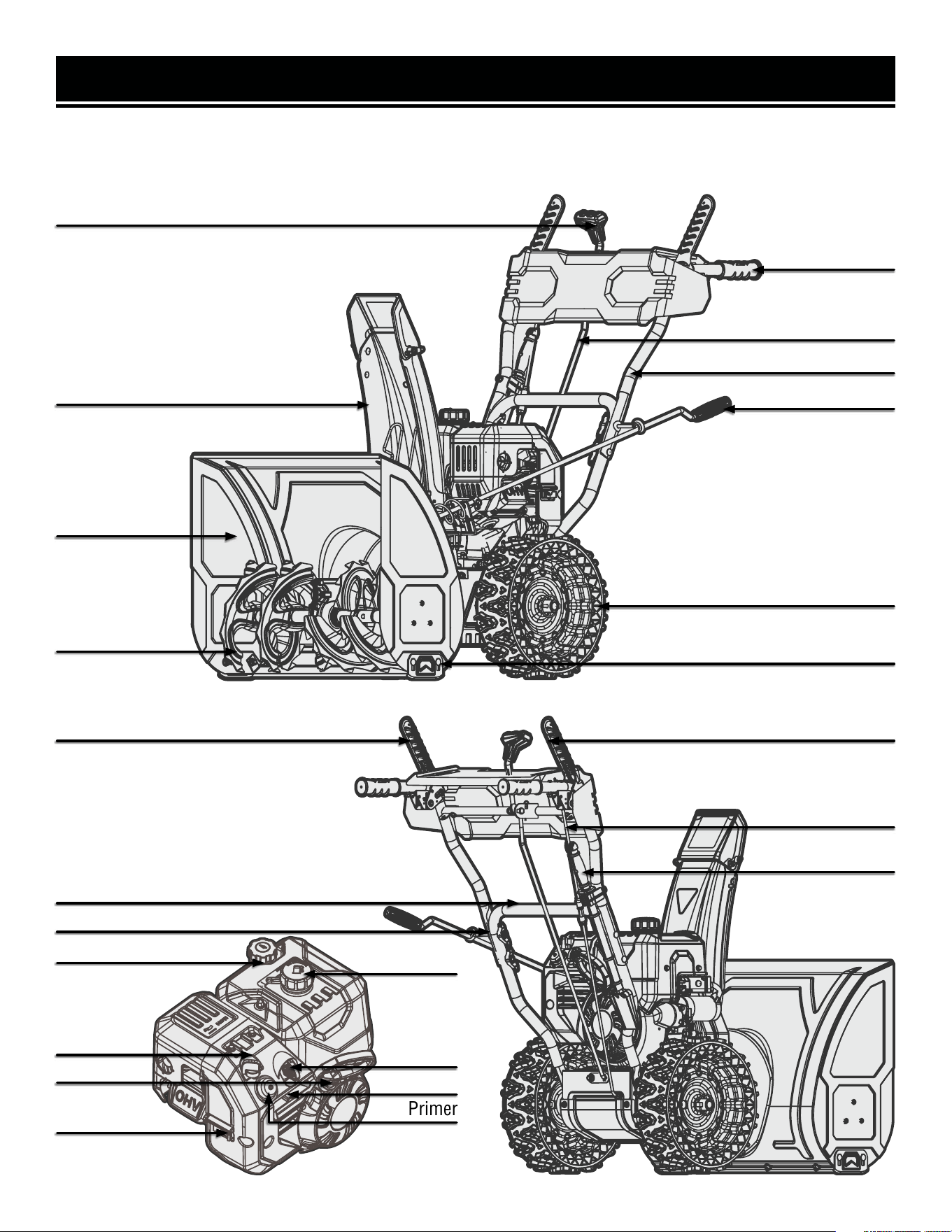
KNOW YOUR SNOW BLOWER
Refer to the following diagrams to become familiarized with all the parts and controls of your snow blower. The
components will be referred to later in the manual for assembly and operation instructions.
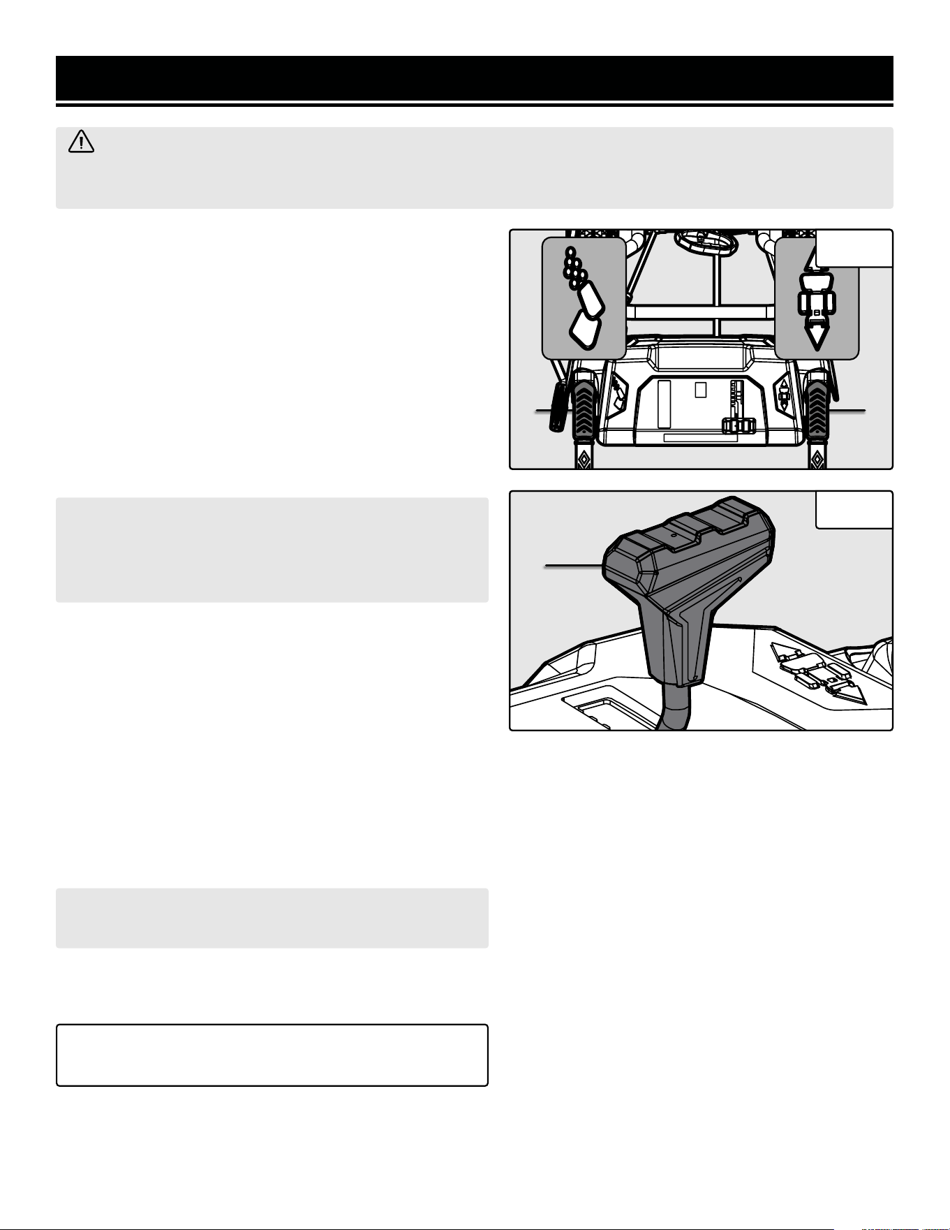
Drive Lever
Auger Lever
Speed Control Lever
Handle
Drive Cable
Auger Cable
Speed Control Rod
Upper Handle
Lower Handle
Chute Rotator
Chute
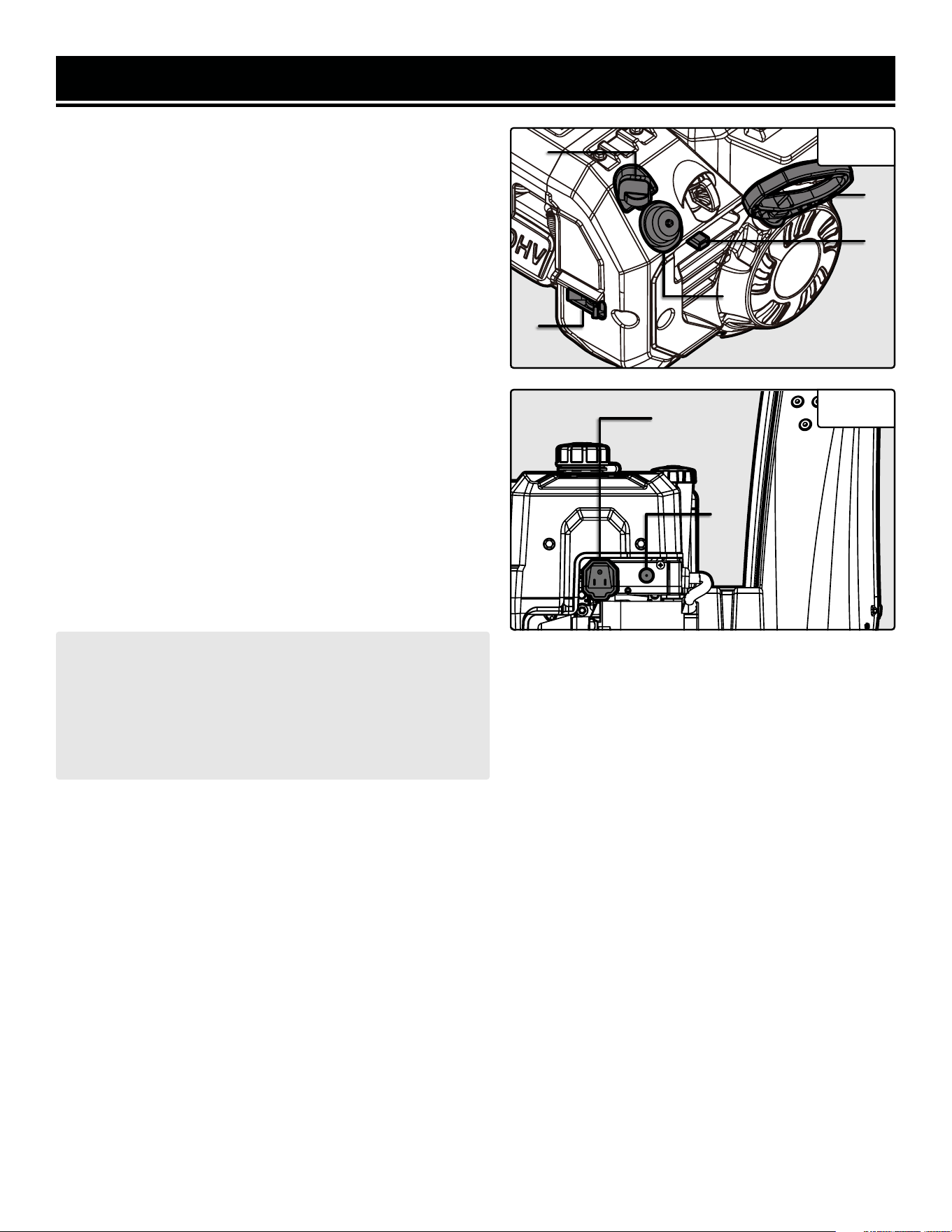
Choke
Fuel Valve
Throttle
Start Key
Recoil Start
Fuel Cap
Oil Fill
Cleaning Tool
Wheel
Skid Plate
Auger
Auger Housing
13
Primer
ASSEMBLY & ADJUSTMENTS
WARNING! Always be sure that the snow blower’s engine is OFF and no extension cord is connected before
adjusting, adding accessories, or checking a function on the machine.
Fig. 1
Fig. 2
2
3
1
4
2
14
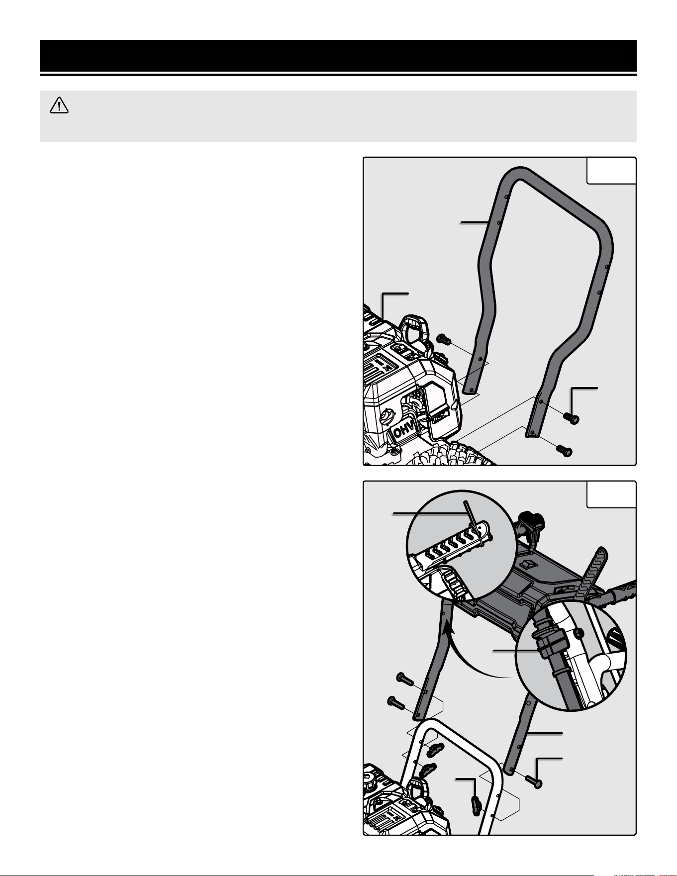
INSTALLING THE LOWER HANDLE
1. Remove the right and left wheels and place them on a
sturdy, flat surface. Set the snow blower body carefully on
top of the wheels to install the lower handle.
2. Remove the pre-installed M8x16 bolts from the back of
the snow blower body (Fig. 1 - 1).
2. Install the lower handle (Fig. 1 - 2) on the back of the
snow blower body using the four M8x16 bolts (Fig. 1 - 3)
as shown in Fig. 1.
INSTALLING THE UPPER HANDLE
NOTE: If you are assembling the snow blower for the first
time, be sure to cut the zipties (Fig. 2 - 1) holding the auger
and drive levers down.
1. Remove the three pre-installed M8x45 lock bolts and lock
knobs from the lower handle.
2. Install the upper handle (Fig. 2 - 2) on the outside of the
of the lower handle using the three included M8x45 lock
bolts (Fig. 2 - 3) and lock knobs (Fig. 2 - 4) as shown in
Fig. 2.
3. Install the cleaning tool (Fig. 2 - 5) onto the right side of
the upper handle using the included M6x25 bolt as shown in
Fig. 2. NOTE: The M6x25 bolt is pre-installed on the clean-
ing tool’s mounting bracket.
3
5
1
ASSEMBLY & ADJUSTMENTS
WARNING! Always be sure that the snow blower’s engine is OFF and no extension cord is connected before
adjusting, adding accessories, or checking a function on the machine.
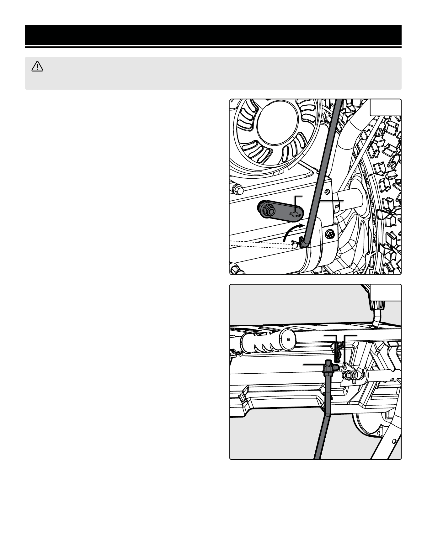
INSTALLING THE DRIVE CONTROL ROD
NOTE: When assembling for the first time, be sure to cut
off the zip ties holding the auger lever and drive lever before
installing the rear end of the drive control rod.
1. Install the rear end of the drive control rod (Fig. 3 - 1) into
the hole on the shift plate (Fig. 3 - 2). Turn the rod to secure
it in place as shown in Fig 3.
2. Install the front end of the drive control rod (Fig. 4 - 1)
into the drive control lever hole (Fig. 4 - 2) and secure it in
place with a cotter pin (Fig. 4 - 3) as shown in Fig. 4.
Fig. 3
Fig. 4
2
1
1
23
15
1
2
ASSEMBLY & ADJUSTMENTS
WARNING! Always be sure that the snow blower’s engine is OFF and no extension cord is connected before
adjusting, adding accessories, or checking a function on the machine.
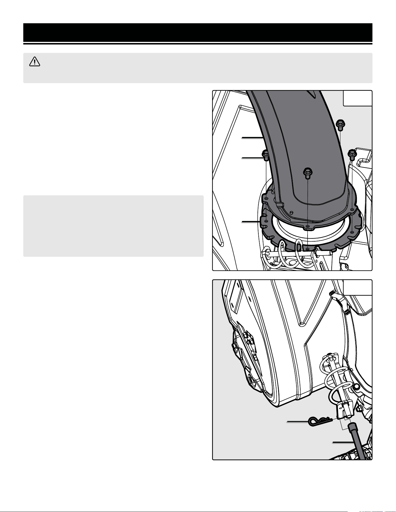
INSTALLING THE CHUTE
1. Remove the pre-installed rotator disc (Fig. 5 - 1) by cut-
ting the zip ties and remove the four M6x20 bolts (Fig. 5 - 2)
from the chute base.
2. Secure the rotator disc and the chute (Fig. 5 - 3) onto the
chute base using four M6x20 bolts. The rotator disc sits
underneath the neck of the chute base; the chute sits on top
of the neck of the chute base. Make sure the spiral vanes on
the chute rotator handle rest in the notches in the side of
the rotator disc.
Fig. 5
Fig. 6
NOTE: Do not over-tighten or the chute will not be able
to rotate. Rotate the chute assembly by hand; if you find
that the chute is difficult to rotate, slightly loosen the
bolts. Make adjustments as necessary until the chute
rotates freely, but does not wobble, on the housing. It
should be securely mounted.
INSTALLING THE CHUTE ROTATOR HANDLE
1. Secure the front end of the chute rotator handle (Fig. 6 -
1) to the chute base using a cotter pin (Fig. 6 - 2) as shown
in Fig. 6.
3
2
1
16
1
2
ASSEMBLY & ADJUSTMENTS
WARNING! Always be sure that the snow blower’s engine is OFF and no extension cord is connected before
adjusting, adding accessories, or checking a function on the machine.
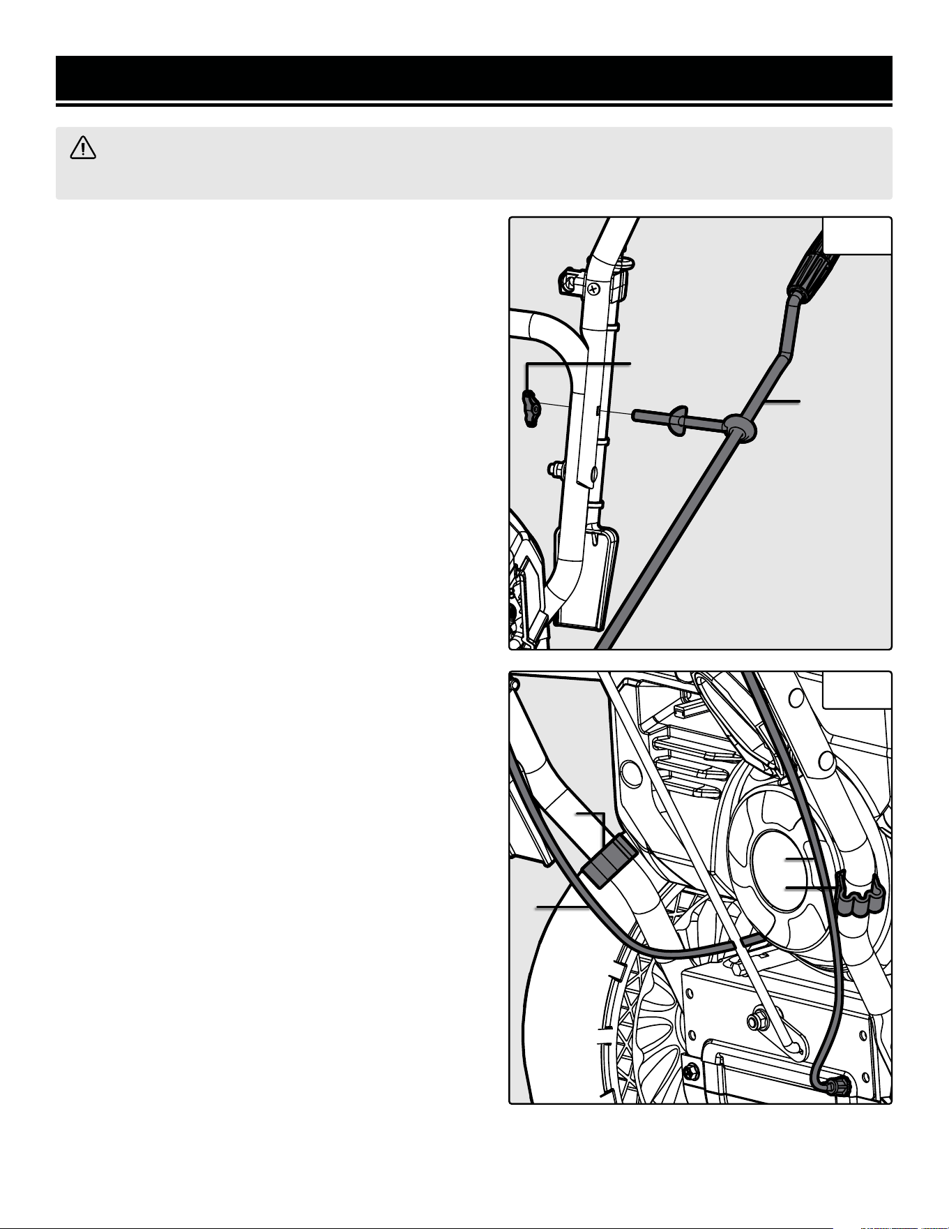
INSTALLING THE CHUTE ROTATOR HANDLE
(CONT.)
2. Secure the rear end of the chute rotator handle (Fig. 7 -
1) to the upper and lower handle using a M8 lock nut (Fig.
7 - 2) as shown in Fig. 7.
SECURING THE AUGER AND DRIVE CABLES
1. Secure the auger cable (Fig. 8 - 1) to the left side of the
handle and the drive cable (Fig. 8 - 2) to the right side of the
handle using the two included cable clips (Fig. 8 - 3).
Fig. 7
Fig. 8
1
2
3
3
17
L
H
The following section describes the necessary steps to prepare the snow blower for use. If you are unsure about
how to perform any of the steps please call 1-847-429-9263 (M-F 8-5 CST) for customer service. Failure to perform
these steps properly can damage the snow blower or shorten its life.
STEP 1 - ADD / CHECK OIL
The user must add the proper amount of oil before operating the snow blower for the first time. The oil capacity of
the engine crankcase is 16.9 fl. oz (0.5 L).
CAUTION! Keep the snow blower level. Tilting the snow
blower to assist in filling will cause oil to flow into the
wrong areas of the engine and cause damage.
SNOW BLOWER PREPARATION
Fig. 10
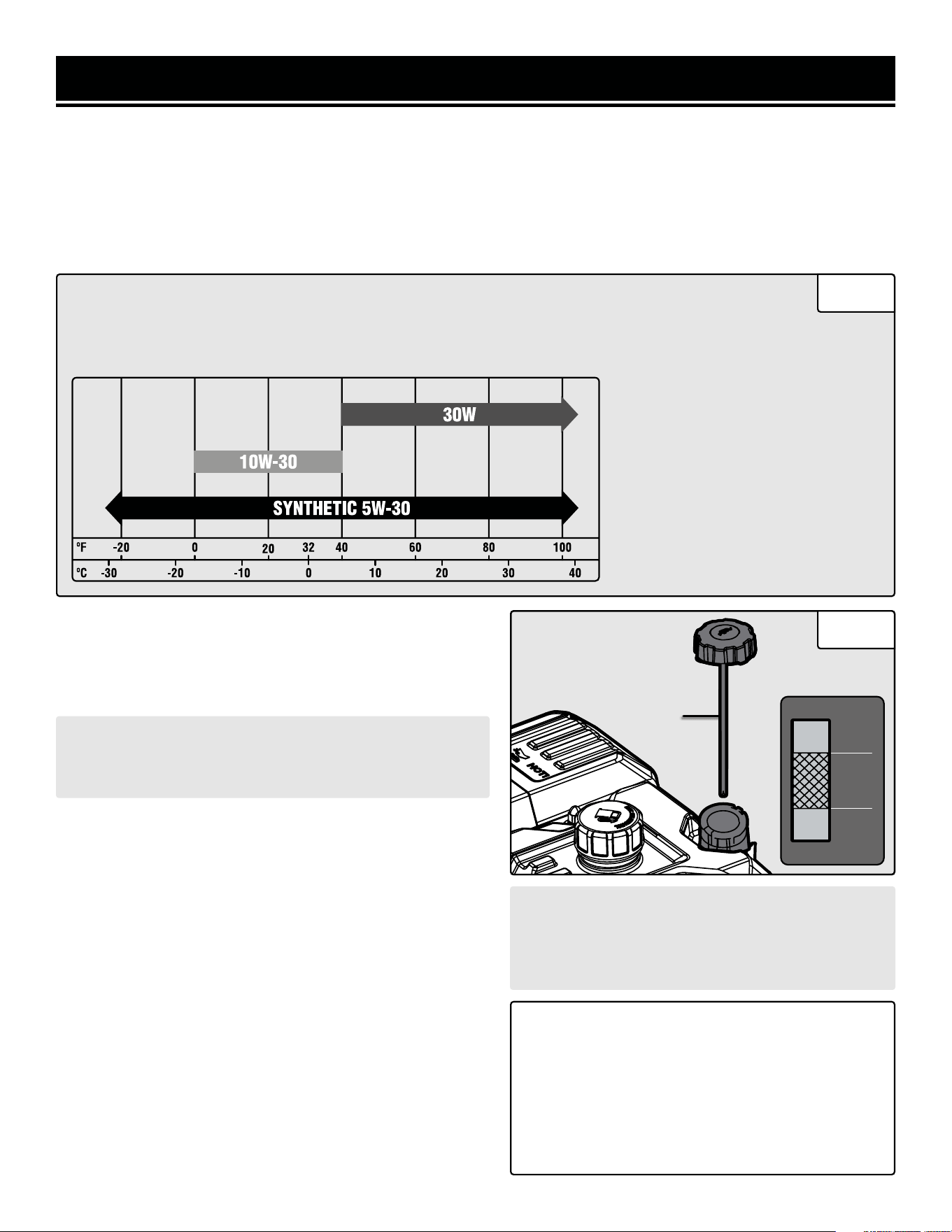
• 30W Engine Oil
Temperatures above 40°F.
• 10W-30 Engine Oil
Temperatures between 0°F - 40°F.
• Synthetic 5W-30 Engine Oil
All temperature ranges.
ENGINE OIL RECOMMENDATIONS - Select good quality detergent oil bearing the American Petroleum Insti-
tute (API) service classifications SJ, SL, or SM (synthetic oils may be used). Select the SAE viscosity grade
of oil that matches the expected operating temperature. For general use (above 40° F), we recommend using
30W engine oil.
To add oil:
1. Place the snow blower on a level surface. Make sure the
engine is off before adding or checking oil.
2. Unscrew the oil dipstick (Fig. 11 - 1) from the engine.
3. Using an oil funnel or appropriate dispenser, slowly add
oil into the oil fill, being careful not to overfill the unit. Use
the dipstick to check the oil level as you fill the tank. The oil
should reach the section between the upper (H) and lower
(L) level. Reinstall the oil dipstick and firmly tighten it. Wipe
clean any spilled oil.
To check oil level (before every subsequent start):
1. Place the snow blower on a level surface. Make sure the
engine is off before adding or checking oil.
2. Remove and wipe the dipstick with a clean rag.
3. Insert the dipstick into the oil fill without screwing it in.
Remove the dipstick to check the oil mark.
4. If the oil mark does not reach the section between the
upper (H) and lower (L) mark on the dipstick, slowly add
oil until the oil mark reaches this section.
CAUTION! For subsequent operation, the oil level
should be checked before each use, or after every
8 hours of operation. Follow the instructions on
this page to check the oil level.
TIP: Your WEN snow blower is compatible with
the WEN 55201 Magnetic Oil Dipstick (not in-
cluded), available for purchase at wenproducts.
com. The dipstick’s industrial-strength magnetic
tip will collect metal shavings from your snow
blower’s oil tank to help preserve the engine and
extend your snow blower’s lifespan.
Fig. 11
1
18
WARNING: RISK OF EXPLOSION. HIGHLY FLAMMABLE: This snow blower may emit highly flammable and
explosive gasoline vapors, which can cause severe burns or even death, if ignited. A nearby open flame can lead
to explosion even if not directly in contact with gasoline.
• Do not operate near open flame, heat, or any other ignition source. Do not smoke near the snow blower.
• Always operate on a firm, level surface.
• Always turn the snow blower off before refueling. Allow the snow blower to cool for at least 2 minutes before
removing fuel cap. Loosen cap slowly to relieve pressure in tank.
• Do not overfill fuel tank. Gasoline may expand during operation. Do not fill to the top of the tank. Allow for
expansion. Always check for spilled fuel before operating.
• If fuel spills, move the snow blower at least 30 feet away from the spill and wipe clean any spilled fuel before
starting the engine.
• Empty fuel tank before storing or transporting the snow blower.
IMPORTANT:
• Avoid getting dirt or water into the fuel tank.
• Keep gasoline away from sparks, open flames,
pilot lights, heat, and other sources of ignition.
• Gasoline can age in the tank and make starting
difficult. Never store the snow blower for more
than 2 months with fuel in the tank.
• Never use an oil/gasoline mixture.
• Never use old gasoline.
NOTE: Do not fill the fuel tank to the very top. If you do
so, gasoline will expand and spill during use, even with
the fuel cap in place.
To check gas level (before every subsequent start):
1. Before starting the snow blower, check to see if there is
sufficient fuel inside the tank.
2. If the tank is empty or low, add gasoline to the gas tank.
See above section, "To add gasoline".
SNOW BLOWER PREPARATION
STEP 2 - ADD / CHECK FUEL
ONLY use fresh (within 30 days from purchase), lead-free
gasoline with a minimum of 87 octane rating. The snow
blower performs best with ethanol-free gasoline. DO NOT
use gasoline with over 10% ethanol.
The capacity of the fuel tank is 0.6 gallons (2.3 L). Do not
mix oil with gasoline.
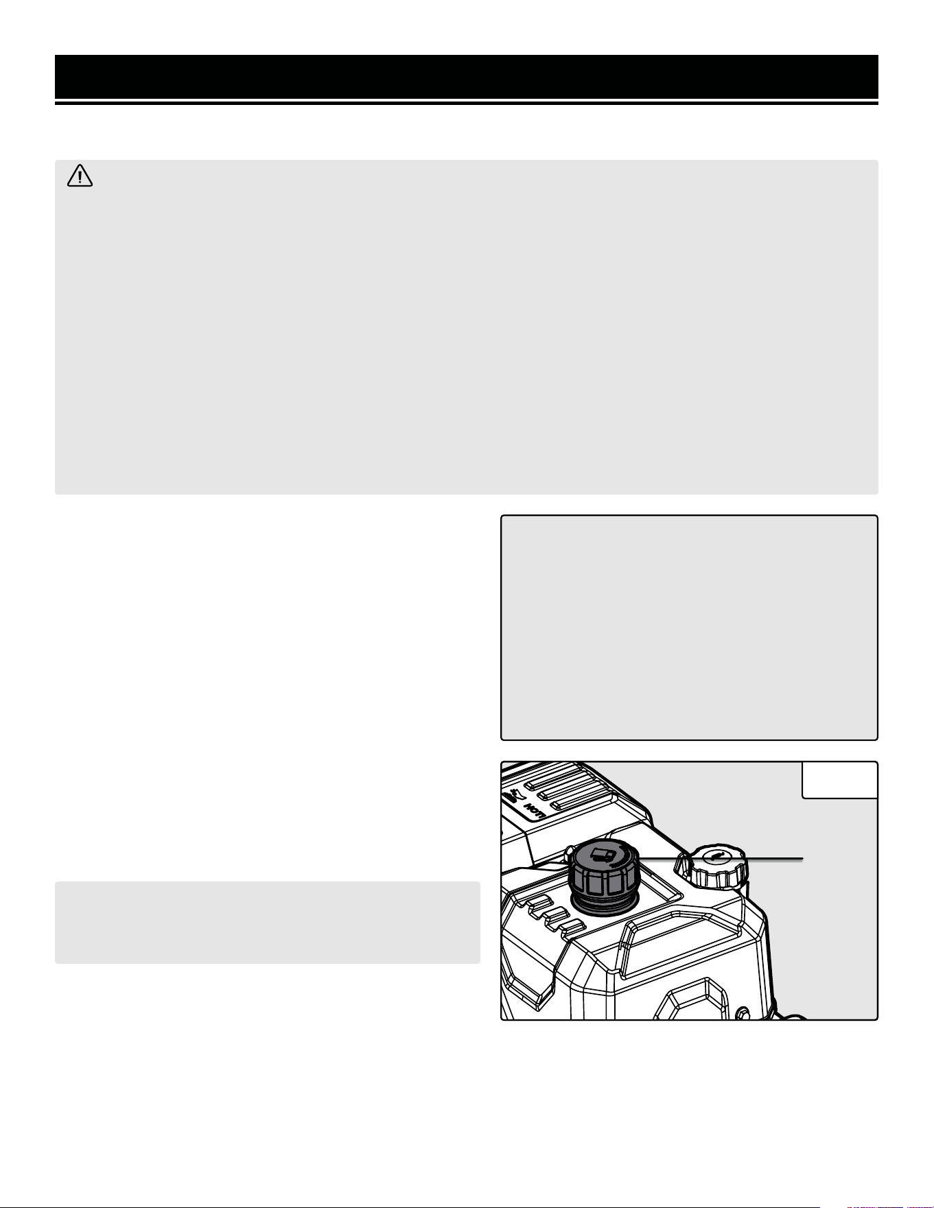
To add gasoline:
1. Place the snow blower on a level surface. Make sure the
engine is off before adding or checking the fuel.
2. Unscrew the fuel cap (Fig. 12 - 1) and set it aside. The
fuel cap may be tight and hard to unscrew.
3. Slowly add unleaded gasoline to the fuel tank. Be careful
not to overfill. Reinstall fuel cap and wipe clean any spilled
gasoline with a dry cloth.
Fig. 12
1
19
SNOW BLOWER PREPARATION
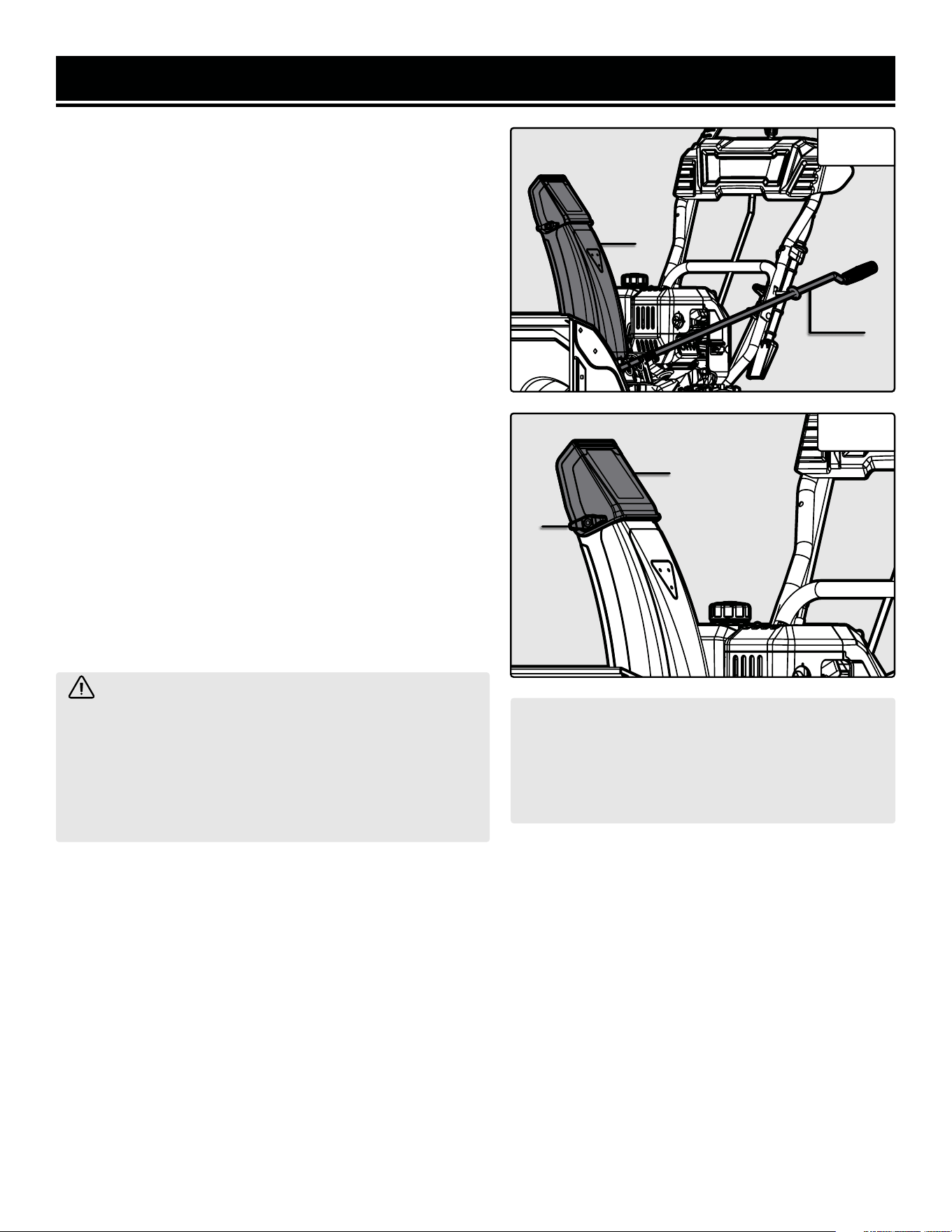
STEP 3 - ADJUST THE CHUTE &
DEFLECTOR PLATE
The direction in which snow is ejected is controlled by the
chute rotator handle (Fig. 13 - 1). Turn the chute rotator
handle to adjust the position of the chute (Fig. 13 - 2).
The angle at which snow is ejected (and therefore how far it
is ejected) is controlled by the chute deflector plate (Fig. 14
- 1). Loosen the knob (Fig. 14 - 2) on the side of the deflec-
tor plate and adjust the plate’s position. Tighten the knob.
HIGH ALTITUDE OPERATION ABOVE 3000 FEET
The fuel system on this snow blower may be affected by
operation at high altitudes. Proper operation can be ensured
by installing an altitude kit at altitudes higher than 3000 feet
above sea level. At elevations above 8000 feet, the engine
may experience a decrease in performance, even with the
proper altitude kit. Operating this snow blower without said
kit may increase the engine’s emissions and decrease both
fuel economy and performance.
You can order the kit at wenproducts.com by searching part
SB209E-HA. This kit should be installed by a qualified me-
chanic. Refer to the instructions included with your altitude
kit for more information about installation.
WARNING! To prevent serious injury from fire,
follow the kit installation procedures in a well-ventilated
area away from ignition sources. If the engine is hot
from use, shut the engine off and wait for it to cool
before proceeding. Do not smoke near the snow blower.
Warranty will be void if adjustments are not made for
high altitude use.
CAUTION! UNINSTALL the high altitude kit when
operating at altitudes below 3000 feet. Engines
with the high-altitude kit installed operated at
lower altitudes could cause severe engine dam-
age and affect emissions compliance.
Fig. 13
Fig. 14
After completing the above preparation, the snow blower is ready to be started.
1
2
1
2
20
DANGER: CARBON MONOXIDE
Using a snow blower indoors CAN KILL YOU IN MINUTES. Snow blower exhaust contains carbon monoxide
(CO). This is a poison gas you cannot see or smell. If you can smell the snow blower exhaust, you are breathing
CO. But even if you cannot smell the exhaust, you could be breathing CO.
NEVER use a snow blower inside homes, garages, crawl spaces, or other partially enclosed areas. Deadly
levels of carbon monoxide can build up in these areas. Using a fan or opening windows and doors does NOT
supply enough fresh air. ONLY use a snow blower outside and far away from windows, doors, and vents. These
openings can pull in snow blower exhaust.
Even if you use a snow blower correctly, CO may leak into the home. ALWAYS use a battery-powered or battery-
backup CO alarm in the home. If you start to feel sick, dizzy, or weak after the snow blower has been running,
move to fresh air RIGHT AWAY. See a doctor. You may have carbon monoxide poisoning.
WARNING: The exhaust from this product contains chemicals known to the State of California to cause
cancer, birth defects, or other reproductive harm.
WARNING: Do not operate snow blower near open flame or flammable materials This snow blower may
emit highly flammable and explosive gasoline vapors, which can cause severe burns or even death if ignited. A
nearby open flame can lead to explosion even if it isn’t directly in contact with gasoline. Do not smoke near the
snow blower.
STARTING YOUR SNOW BLOWER
Before starting the snow blower, make sure you have read and performed the steps in the “SNOW BLOWER PREPA-
RATION” section of this manual. If you are unsure about how to perform any of the steps in this manual please call
1-847-429-9263 (M-F 8-5 CST) for customer service.
BEFORE STARTING YOUR SNOW BLOWER
1. Verify that the snow blower is outside on a level surface
with at least 2 feet of clearance on all sides.
2. Check that there is a sufficient level of oil in the crank-
case. Add oil if necessary, see the “Step 1 - Add / Check
Oil” section.
3. Check that there is a sufficient level of gasoline in the fuel
tank. Add fuel if necessary, see the “Step 2 - Add / Check
Fuel” section.
4. Check that the chute and deflector plate are pointing
in the desired direction. Adjust the chute and deflector if
necessary, see the “Step 3 - Adjust The Chute & Deflector
Plate” section.
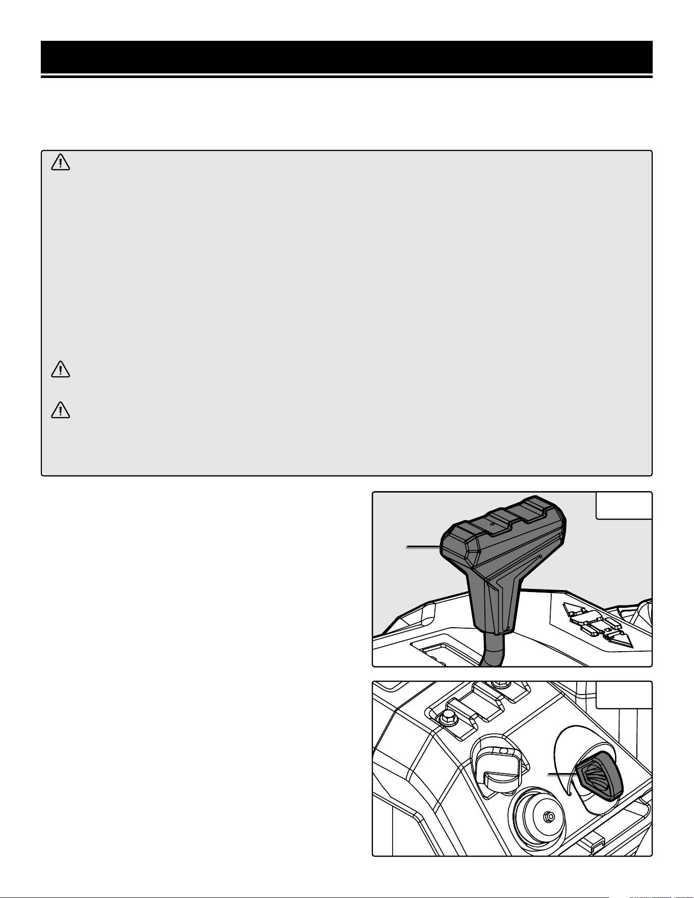
STARTING THE SNOW BLOWER
1. Release the drive lever (Fig. 19 - 2) on the right handle.
Put the speed control lever (Fig. 15 - 1) in the low, forward
position (F1).
2. Insert the start key (Fig. 16 - 1) into the engine until it
clicks into place.
Fig. 15
Fig. 16
1
1
F1
21
STARTING YOUR SNOW BLOWER
STARTING THE SNOW BLOWER (CONT.)
3. Turn the fuel valve (Fig. 17 - 1) to the ON position.
4. Turn the choke knob (Fig. 17 - 2) to the CLOSED/START
position.
5. Make sure the throttle (Fig. 17 - 3) is in the FAST (rabbit)
position.
6. Push the primer bulb (Fig. 17 - 3) 3 - 5 times. This helps
the engine start more easily in lower temperatures.
7. Follow step A for electric start, or B for recoil start.
A. For electric start:
1. Connect an extension cord to the electric start port
(Fig. 18 - 1). See the “Electrical Information” section
for extension cord guidelines.
2. Press and hold the start button (Fig. 18 - 2) on the
electric start box for 5 seconds.
3. If the engine does not start, wait 5 - 10 seconds, then
try again. Check that the adjustments in steps 1 - 5 have
been performed properly.
CAUTION! Do not try to start the engine more than 10
times. If after 10 times the engine does not start, wait 40
minutes before trying again. If problems persist, consult
the troubleshooting guide. If the steps in the guide do
not resolve the problem, call customer service at 1-847-
429-9263, M - F, 8 - 5 CST.
4. Once the engine has started, slowly return the choke
knob all the way to the OPEN/RUN position.
5. When finished, disconnect the extension cord from
the wall receptacle, then from the electric start box.
B. For recoil start:
1. Pull on the recoil starter handle (Fig. 17 - 5) slowly
until a slight resistance is felt, then pull quickly to start
the engine. Return cord gently into the recoil starter.
Never allow the cord to snap back. If engine fails to
start, repeat this step.
2. Once the engine has started, slowly return the choke
knob all the way to the OPEN/RUN position.
3. Allow the engine to run for 30 - 60 seconds before
beginning to clear snow.
Fig. 17
Fig. 18
1
2
4
3
1
2
5
22
CONTROLS
1. Squeeze the auger lever (Fig. 19 - 1) to spin the auger
and throw snow. To adjust the position of the chute and
chute deflector plate, see the “Step 3 - Adjust The Chute &
Deflector Plate” section.
2. The direction and speed of the snow blower’s motion is
controlled by the speed control lever (Fig. 20 - 1). There are
six speed settings in forward and two in reverse.
3. Squeeze the drive lever (Fig. 19 - 2) to allow the wheels
to spin and move the snow blower.
WARNING! Do not plug in or turn on the tool until it is fully assembled according to the instructions. Read
through and become familiarized with the following procedures of handling and adjusting your tool. Failure to
follow the safety instructions may result in serious personal injury.
TURNING THE SNOW BLOWER OFF
1. Release the auger and drive levers.
2. Put the speed control lever in the low, forward position
(F1).
3. Run the auger for 30 - 60 seconds to clear out any re-
maining snow inside the auger housing or chute, then re-
lease the auger lever.
4. Turn the fuel valve (Fig. 17 - 1) to OFF. This burns the fuel
out of the carburetor and prolongs engine life.
CAUTION! Always disengage the drive lever before
changing speeds! Failure to perform this step could lead
to clutch or transmission damage and will void the war-
ranty.
NOTE: To shut down the engine immediately, pull the
engine key out.
TIP: Turn the chute through its full range of motion a
couple of times to prevent ice buildup.
5. Remove the engine key. Store it in a safe place out of the
reach of children.
OPERATION
Fig. 19
Fig. 20
1 2
1
23

WARNING! Do not plug in or turn on the tool until it is fully assembled according to the instructions. Read
through and become familiarized with the following procedures of handling and adjusting your tool. Failure to
follow the safety instructions may result in serious personal injury.
OPERATION
NOTE: The auger blades are mounted to their shaft with shear pins that are designed to break if a foreign object
enters the auger housing. This is to prevent machine damage and operator or bystander injury. For information
on replacing the shear pins, see the “Replacing Shear Pins” section.
TIPS FOR EFFECTIVE SNOW BLOWING
• Always run the engine at full throttle.
• Adjust the drive speed to the situation at hand. Let the machine do the work.
• It is easier and more efficient to remove snow immediately after it falls.
• Throw snow downwind whenever possible.
• Don’t use the snow blower early in the morning, if possible. You know how your neighbor Greg is about noise.
• On flat surfaces (such as concrete, asphalt, etc.), adjust the skid plates so that the bottom of the scraper bar
runs along the ground.
• On uneven surfaces (such as gravel, crushed rock, etc.) raise the scraper bar slightly above the top of the gravel
surface. Ensure that gravel and stones do not enter the auger housing, as they could cause injuries if they are
ejected.
• Clear clogs immediately, see “Clearing Clogs” below.
• If the auger or drive do not engage when the handle is squeezed, release it immediately and turn the engine OFF.
CLEARING CLOGS
A clearing tool is included with your snow blower.
1. Turn the engine OFF and wait for all moving parts (wheels, impeller, auger blades, etc.) to stop moving.
2. Use the clearing tool to clear the clog.
3. Replace the clearing tool in the clasp on the frame.
WARNING! NEVER use your hands to clear a clog! Only use the clearing tool.
4. Run the auger for a few seconds to clear out any remaining snow or ice.
24

MAINTENANCE
WARNING! Make sure the engine is OFF, the key is removed, all moving parts have stopped, and the snow
blower has cooled down before performing any maintenance. Failure to comply may cause serious injury.
NOTE: Failure to properly maintain the snow blower will void the warranty.
RECOMMENDED MAINTENANCE SCHEDULE
Proper routine maintenance of the now blower will help prolong the life of the machine. Please perform maintenance
checks and operations according to the maintenance schedule below, Table 1. If there are any questions about the
maintenance procedures listed in this manual, please contact customer service at 1-847-429-9263 (M-F 8-5 CST),
or email [email protected].
IMPORTANT SNOW BLOWER MAINTENANCE TIPS:
• Drain your carburetor after each use and before storage to prevent it from clogging.
• Do not store the snow blower with fuel inside the tank for more than 2 months - the fuel will go bad.
• Run the snow blower for 20 to 30 minutes every month to maximize its lifespan.
Recommended
Maintenance Schedule
(Snow Blower)
Every 8
Hours or
Daily
Every 25
Hours
Every 3
Months or 50
Hours
Every 6
Months or
100 Hours
Before
Storage
As
Necessary
Tires Inspect X
Impeller & Auger
Inspect X
Clear X
Shear Pins Replace X
Scraper Bar Replace X
Skid Plates Replace X
Drive & Auger
Cables
Inspect X
Adjust Tension X
Body Clear Snow/Ice X X
Drive Belts
Inspect X
Replace X
Auger Gears Lubricate X
Friction Disc Replace X
Recommended
Maintenance Schedule
(Engine)
Every 8
Hours or
Daily
Every 25
Hours
Every 3
Months or 50
Hours
Every 6
Months or
100 Hours
Before
Storage
As
Necessary
Engine Oil
Check Level X
Replace X* X
Spark Plug
Check/Clean/
Regap
X
Carburetor Drain X X
Fuel
Check Level X
Drain X X
Table 1 - Recommended Maintenance Schedule* Clean/change more often under harsh conditions or operating under heavy load.
25
WARNING! Any attempt to repair or replace electrical parts on this tool may be hazardous. Servicing of the
tool must be performed by a qualified technician. When servicing, use only identical WEN replacement parts.
Use of other parts may be hazardous or induce product failure.
MAINTENANCE
TIRE MAINTENANCE
Inspect the tires after each use for wear and tear. Keep the
tires away from gasoline, oil, and other chemicals to pre-
vent degradation of the rubber. Avoid running over stumps,
stones, ruts, glass, knives, sea urchins, porcupines, and
other sharp objects that could damage the tires.
IMPELLER & AUGER MAINTENANCE
Check the impeller and auger for snow, ice, and debris be-
fore and after use. Remove any snow, ice or debris before
storing the snow blower, or starting it.
CAUTION! NEVER use an open flame (such as a lighter,
blowtorch, or flamethrower) to melt snow or ice. Bring
the snow blower to a heated area and let the snow or ice
melt on its own, or use a hair dryer or heat gun.
Fig. 21
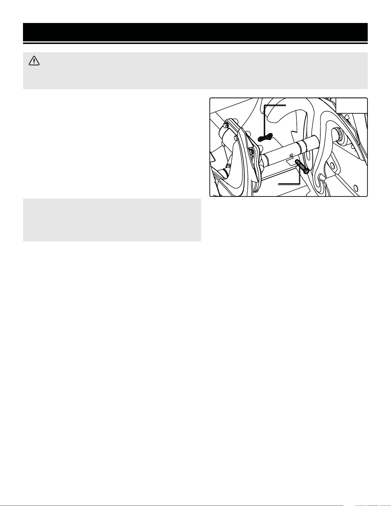
REPLACING SHEAR PINS
If a shear pin fails, it has done its job in protecting the
product from damage. Replacement shear pins and
bowtie clips can be ordered from wenproducts.com
(Part SB209E-1626 and SB209E-1627). Shear pins
and bowtie clips are not covered under the warranty.
To replace the shear pins, stop the engine and wait for
the auger blades to come to a complete stop. Install
a new shear pin (Fig. 21 - 1) and bowtie clip (Fig. 21
- 2). Your snow blower comes with two spare shear
pins and two spare bowtie clips.
SCRAPER BAR MAINTENANCE
Check the scraper bar for excess wear - if it has be-
gun to exhibit signs of severe wear, it is time to re-
place it. Replacement scraper bars can be ordered
from wenproducts.com (Part SB209E-1616). Scrap-
er bars are a wear-out part and are not covered under
the warranty.
To replace the scraper bar, remove the four nuts and
bolts that secure the scraper bar to the auger hous-
ing. Install the new scraper bar and replace the nuts
and bolts. Securely tighten the nuts.
2
1
26
SNOW BLOWER BODY MAINTENANCE
Keep the body of the snow blower clean to prevent improper operation or machine damage from dirt & debris. In-
spect all ventilation openings on the snow blower. These must be kept clean and unobstructed. Wipe down the snow
blower’s housing with a damp cloth and mild detergent. Dry it with a towel.
SKID PLATE MAINTENANCE
Check the skid plates for excess wear - if they have begun to exhibit signs of severe wear, it is time to replace them.
Replacement skid plates can be ordered from wenproducts.com (Part SB209E-1614). Skid plates are a wear-out
part and are not covered under the warranty.
To replace a skid plate, remove the nuts and bolts that secure the skid plate to the auger housing. Install the new
skid plate and replace the nuts and bolts. Securely tighten the nuts.
NOTE: Do not clean the snow blower with water alone – it will freeze in low temperatures and cause machine
damage. Do not get soap or water inside of your snow blower.
MAINTENANCE
CHECKING & CHANGING OIL
Check the oil according to the Recommended Maintenance
Schedule chart. The oil capacity of the engine is 16.9 fl. oz
(0.5 L). Add oil when the oil level is low. This is a critical
step for proper engine starting. To check the oil level and/or
add oil, see “Step 1 - Add/Check Oil”.
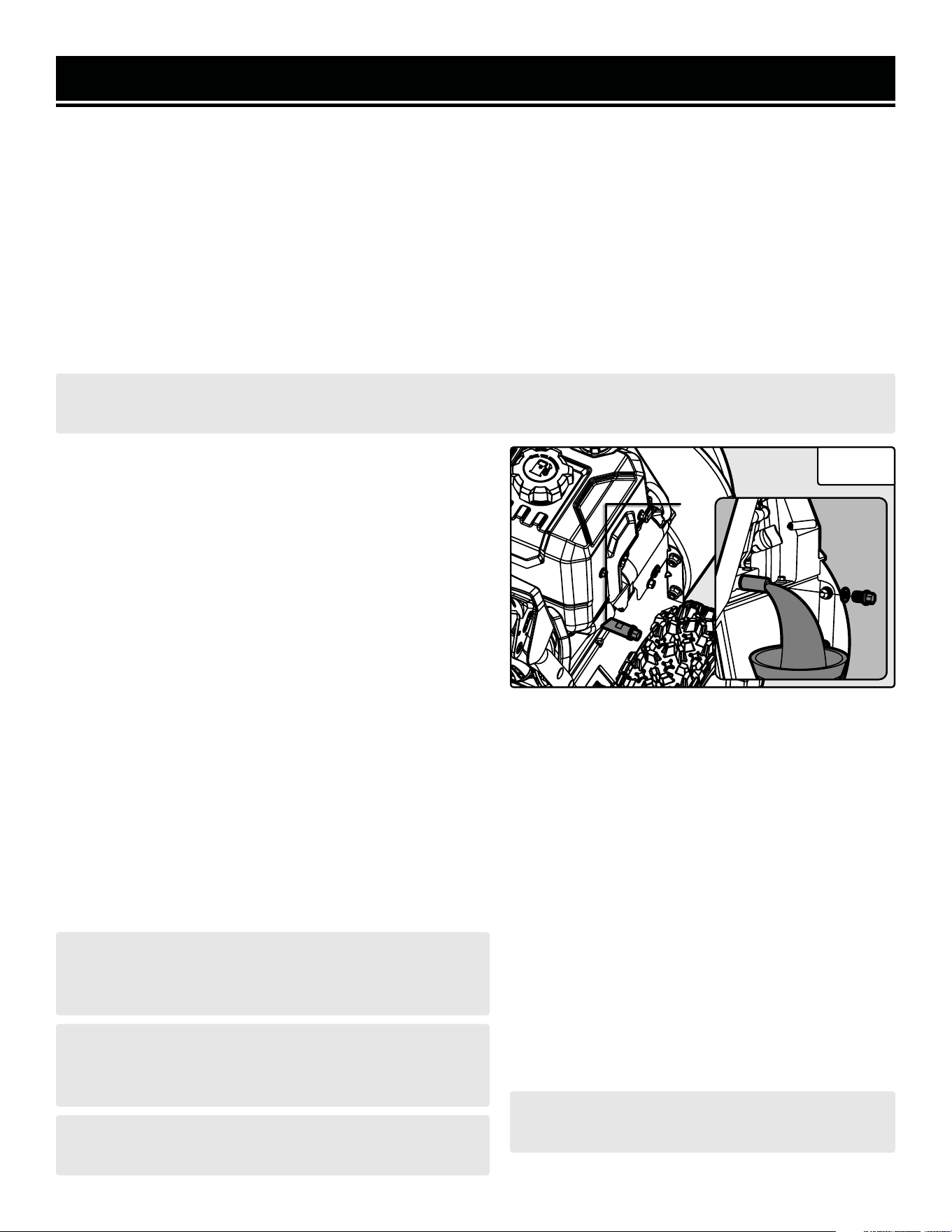
To change the oil:
1. Run the engine for a few minutes to warm the oil up.
Warm oil flows more easily.
2. Remove the wheel pin and the wheel and set them aside.
3. Prepare an approved oil-storage container underneath
the oil drain bolt (Fig. 22).
NOTE: To avoid spills from the carburetor bowl, drain the
carburetor before draining the oil.
4. Unscrew the oil drain bolt and allow oil to drain from the
engine completely.
5. Reinstall the oil drain bolt and tighten it securely. Wipe
clean any oil spillage.
6. To add new oil, see “Step 1 - Add/Check Oil”.
Fig. 22
NOTE: Never dispose of used engine oil in the trash or
down a drain. Please call a local recycling center or auto
garage to arrange proper oil disposal.
CAUTION! Never run the engine with low oil, or with no
oil. Doing so will permanently damage the engine and
void the warranty.
CAUTION! Let the muffler cool down completely before
performing spark plug maintenance.
DRAINING THE CARBURETOR
Drain the carburetor after every use and before
storing the snow blower (refer to the Recommended
Maintenance Schedule on page 28). Draining the
carburetor can help prevent build-up and blockages
caused by stagnant fuel inside of the carburetor.
1. Prepare an approved gasoline-storage container
under the carburetor to collect the drained fuel. Make
sure the fuel valve is turned OFF.
2. The carburetor can be accessed from the left side
of the snow blower, next to the cylinder head cover.
To drain the carburetor, open up the carburetor drain
screw with a Phillips-head screwdriver and drain out
any gasoline that has built up inside.
3. Once the fuel has drained, close the drain screw.
NOTE: Make sure to drain your carburetor before
storing the snow blower for long periods of time.
1
27
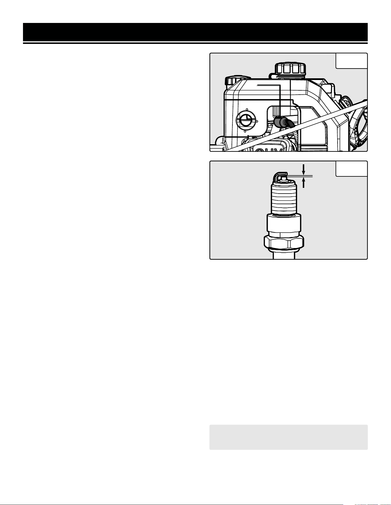
Fig. 23
SPARK PLUG MAINTENANCE
Inspect and change the spark plug every 100 hours of op-
eration (refer to the Recommended Maintenance Schedule
chart). The spark plug is important for proper engine op-
eration. Check the spark plug regularly to maintain proper
engine operation. A good spark plug should be intact, free
of deposits, and properly gapped.
1. Gently pull on the spark plug boot (Fig. 23 - 1) to remove
it. Be careful not to tear insulation or wire.
2. Use a spark plug wrench or socket (not included) to un-
screw the spark plug from the engine. Remove the spark
plug from the engine.
MAINTENANCE
3. Visually inspect the spark plug. If it is cracked or chipped,
or if the electrodes are worn or burned, discard it and re-
place with a new spark plug. We recommend replacing it
with a Torch F6TC (NGK BP6ES) spark plug. These can be
purchased from wenproducts.com by searching part num-
ber 56310i-0104.
4. If re-using the spark plug, use a wire brush to clean any
dirt from around the spark plug base, then re-gap the spark
plug.
5. Measure the plug gap with a spark plug gap gauge. The
gap should be 0.7mm - 0.8mm (0.028 in. - 0.031 in.). Care-
fully adjust the gap if necessary (Fig. 24).
6. Screw the spark plug back into the spark plug hole using
the spark plug wrench. Do not over-tighten spark plug. Rec-
ommended tightening of the spark plug is ½ to ¾ of a turn
after the spark plug gasket contacts the spark plug hole, or
14.75 - 19.18 ft-lb (20 - 26 Nm).
7. Reinstall the spark plug boot over the spark plug.
Fig. 24
CAUTION! Store the emptied gasoline in a suitable
place. Never store fuel for more than 2 months.
DRAINING THE FUEL TANK
Drain and clean the fuel tank each year, or before
storing the snow blower for longer than two months.
1. Prepare an approved gasoline-storage container
under the carburetor. Make sure the fuel valve is
turned OFF.
2. Remove the carburetor drain screw. Set it aside.
3. Turn the fuel valve to ON and let the fuel tank drain
completely This may take a while, depending on how
much gasoline remains in the tank.
4. Once the fuel has drained, replace the drain screw
and turn the fuel valve OFF.
5. Start and run the engine until the fuel runs out.
Then, drain the carburetor.
0.7mm - 0.8mm
1
28
STORAGE
WARNING! Avoid direct sunlight inside a vehicle. If the snow blower is left in an enclosed vehicle for many
hours, the high temperature could cause the fuel to vaporize and result in a possible explosion.
WARNING! Store the snow blower upright in a cool and dry location, away from sources of heat, open
flames, sparks or pilot lights.
Shut off the snow blower and allow the unit to cool to room temperature before storing it. NEVER place any type of
storage cover on the snow blower while it is still hot. Do not obstruct any ventilation openings.
Follow the procedures below for properly storing your snow blower. We highly recommend running your snow
blower once a month for 20 to 30 minutes, to ensure it is ready when you need it.
For Short Periods (30 to 60 Days):
• Drain the carburetor. Refer to "Draining The Carburetor".
• Add fuel stabilizer: Follow the suggested portions and
instructions of your preferred stabilizer. Run the engine for 15 to
20 minutes, allowing the fuel stabilizer to mix with the gasoline
and circulate through the carburetor, and then top off with fuel.
Filling the fuel tank full reduces the amount of air in the tank and
helps fight deterioration of fuel.
For Extended Periods (Over 60 Days):
• Drain the fuel tank and carburetor. Refer
to "Draining The Fuel Tank" and "Draining
The Carburetor".
• Never store snow blower with fuel in the
tank for more than two months.
• Change the engine oil. Refer to "Checking
& Changing Oil".
PRODUCT DISPOSAL
Do not dispose of used snow blower or parts with your household waste. This product contains electrical or elec-
tronic components that should be recycled. Please take this product to your local recycling facility for responsible
disposal to minimize its environmental impact.
Do not dispose of used oil or fuel in the trash or down a drain. Please contact your local recycling center or auto
garage to arrange proper oil/fuel disposal.
Please recycle the packaging and electronic components where facilities exist.
MAINTENANCE
29

TROUBLESHOOTING GUIDE
PROBLEM POSSIBLE CAUSE SOLUTION
Engine idles roughly or runs
roughly.
1. Choke improperly adjusted. 1. Adjust choke.
2. Fuel line blocked. 2. Clean fuel line.
3. Engine is filled with
contaminated or old fuel.
3. Drain fuel tank and carburetor. Replace with fresh
gasoline (87 octane, 10% ethanol maximum).
4. Bad carburetor.
4. Contact customer service at 1-847-429-9263
M-F 8-5 CST for assistance.
Excessive vibration.
1. Loose/damaged augers or
loose part.
1. Tighten all fasteners. Check that auger shear pins
are intact. Replace shear pins if needed.
2. Engine adjustment problem.
2. Contact customer service at 1-847-429-9263
M-F 8-5 CST for assistance.
Loss of drive traction, or
slowing of drive speed.
1. Wheel V-belt is worn, is
slipping, or is off the pulley.
1. Check V-belt. Contact customer service at
1-847-429-9263 M-F 8-5 CST for assistance.
2. Worn friction disc.
3. Contact customer service at 1-847-429-9263
M-F 8-5 CST for assistance.
Loss of snow discharge, or
slowing of snow discharge.
1. Chute deflector or chute is
clogged.
1. Shut off engine and clear clog.
2. Auger is blocked. 2. Shut off engine and clear blockage.
3. Broken shear pin. 3. Replace shear pin.
4. Worn friction disc.
4. Contact customer service at 1-847-429-9263
M-F 8-5 CST for assistance.
Chute difficult to move.
1. Snow or ice is blocking chute
rotation.
1. Clear snow or ice.
2. Mounting nuts too tight. 2. Loosen mounting nuts.
Product turns to one side or
leans to one side.
1. Uneven wheel wear. 1. Check both wheels; replace if needed.
2. Wheel lock pin disengaged
from wheel axle on one side.
2. Ensure both wheel lock pins go through the
wheels and the wheel axle.
3. Uneven skid plate adjustment. 3. Adjust skid plates height.
WARNING! Stop using the tool immediately if any of the following problems occur. Repairs and replacements
should only be performed by an authorized technician. For any questions, please contact our customer service
at 1-847-429-9263, M-F 8-5 CST or email us at [email protected].
Troubleshooting guide continues on the next page.
30

TROUBLESHOOTING GUIDE
PROBLEM POSSIBLE CAUSE SOLUTION
Engine will not start.
1. Engine key not inserted. 1. Insert engine key fully.
2. Not enough gasoline in tank. 2. Fill tank.
3. Fuel valve is OFF. 3. Turn fuel valve to ON.
4. Choke is set to OPEN / RUN
(cold engine).
4. Set choke to CLOSED / START.
5. Choke is set to CLOSED /
START (warm engine).
5. Set choke to OPEN / RUN.
6. Primer bulb was not pushed. 6. Push primer bulb.
7. Engine is flooded.
7. Wait 5 minutes. DO NOT prime engine. Restart
engine with choke in CLOSED / START position.
8. Engine is filled with
contaminated or old fuel.
8. Drain fuel tank and carburetor. Replace with fresh
gasoline (87 octane, 10% ethanol maximum).
9. Carburetor is air-locked.
9. Turn fuel valve to OFF. Remove bolt from bottom
of carburetor. Remove carburetor bowl and allow
float to reset. Replace bowl and re-install bolt.
10. Spark plug boot
disconnected.
10. Connect spark plug boot to spark plug.
11. Spark plug dirty or broken. 11. Examine spark plug. Clean or replace as needed.
12. Electric start: power cord not
connected.
12. Connect power cord.
13. Electric start: no line voltage. 13. Check line voltage at power source.
14. Electric start: power cord
gauge too low or power cord
too long.
14. Refer to chart on p. 9 for recommended power
cord length and gauge.
15. Faulty ignition coil.
15. Contact customer service at 1-847-429-9263 M-F
8-5 CST for assistance.
16. Electric start: faulty starter
motor or control box.
16. Contact customer service at 1-847-429-9263 M-F
8-5 CST for assistance.
Decreased power.
1. Too much snow being blown.
1. Decrease forward speed. Blow a narrower path
through the snow.
2. Fuel tank cap covered in snow
or ice.
2. Clean fuel tank cap.
3. Muffler dirty or clogged.
3. Shut off engine and wait for it to cool down. Clean
muffler.
4. Improper cable length. 4. Adjust cable length or replace cable.
5. Carburetor air intake is
blocked.
5. Check and clear carburetor.
31
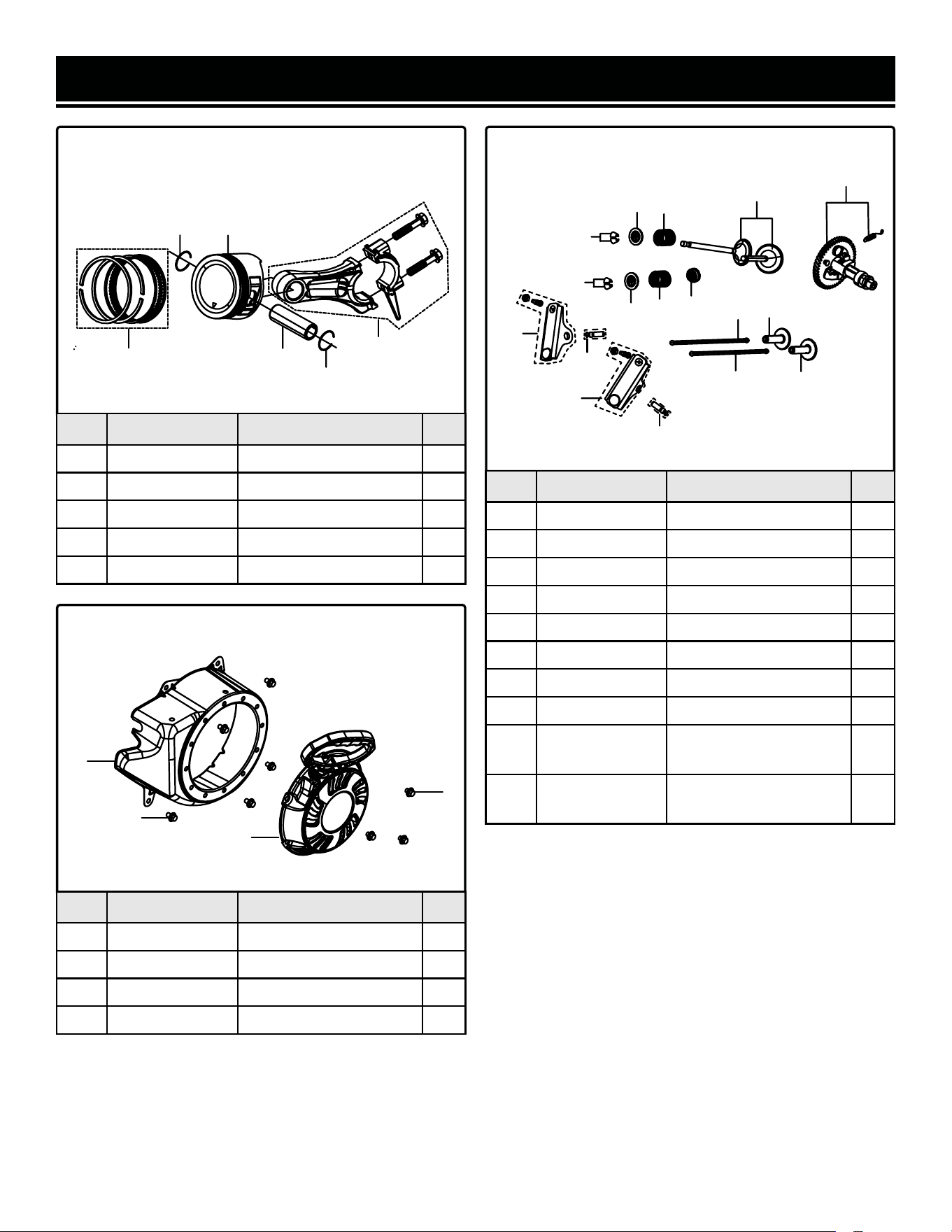
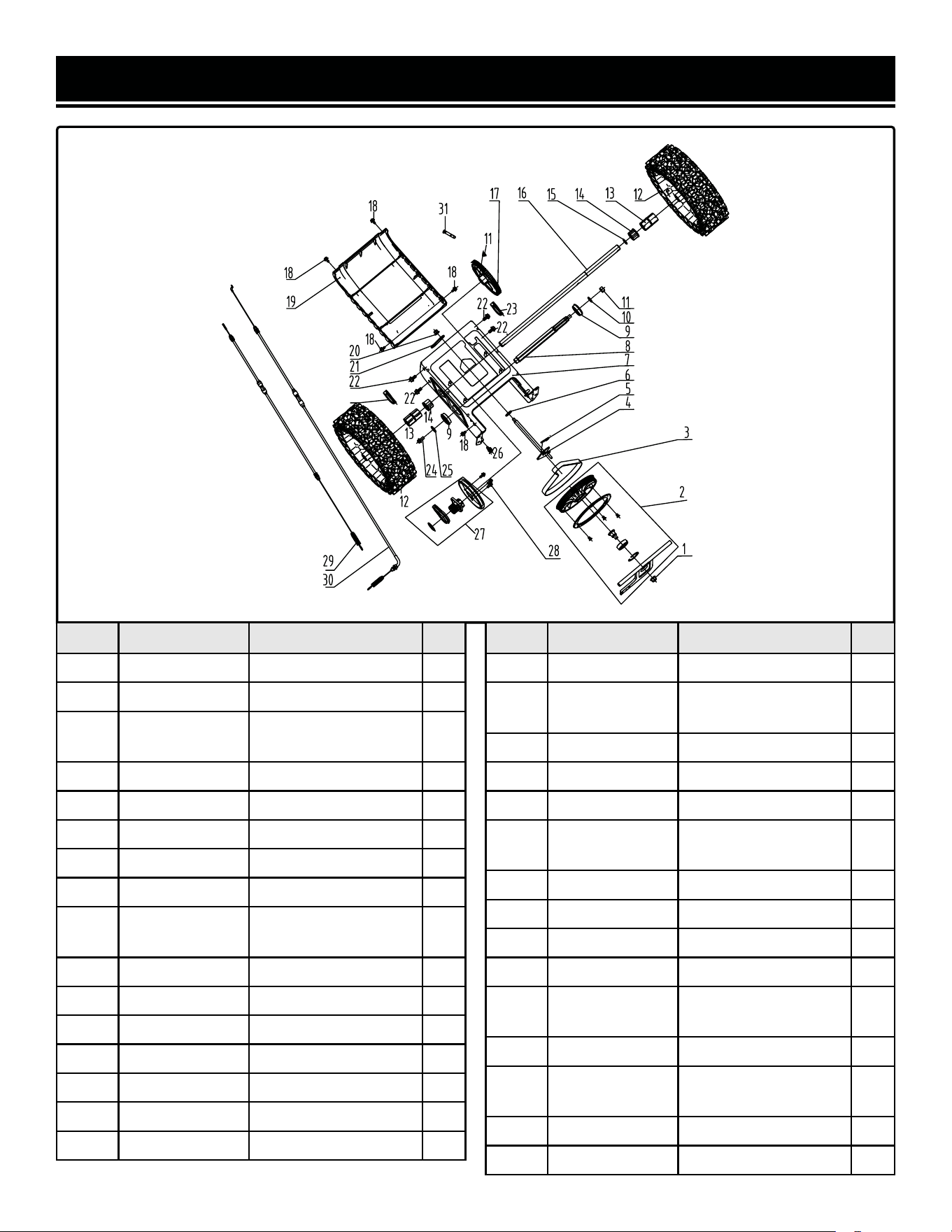
EXPLODED VIEW & PARTS LIST
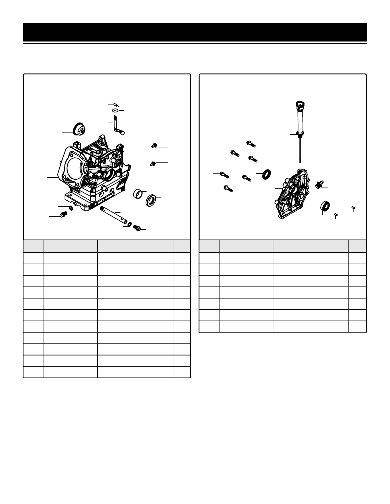
No. Part No. Description Qty.
1-1 SB209E-0101 Bolt, M6x25 2
1-2 SB209E-0102 Governor Gear Assembly 1
1-3 SB209E-0103 Crankcase 1
1-4 56380i-0102 Flat Washer 3
1-5 SB209E-0105 Drain Plug Bolt, M10x15 3
1-6 SB209E-0106 Bushing 1
1-7 SB209E-0107 Oil Seal 1
1-8 SB209E-0108 Oil Drain Tube 1
1-9 SB209E-0109 Cotter Pin 1
1-10 SB209E-0110 Flat Washer 1
1-11 SB209E-0111 Governor Arm 1
FIG. 1. CRANKCASE &
GOVERNOR GEAR ASSEMBLY
FIG. 2. CRANKCASE COVER
No. Part No. Description Qty.
2-1 SB209E-0201 Bolt, M8x32 6
2-2 SB209E-0202 Oil Seal 1
2-3 SB209E-0203 Oil Dipstick Assembly 1
2-4 SB209E-0204 Crankcase Cover 1
2-5 SB209E-0205 Engine Oil Plug 1
2-6 56380i-0203 Bearing, 6205 1
2-7 56200-0803 Pin 2
2
3
4
5
6
7
8
9
1
4
5
10
11
1
1
2
3
4
5
6
7
7
NOTE: Not all parts may be available for purchase. Parts and accessories that wear
down over the course of normal use are not covered under the warranty.
32
EXPLODED VIEW & PARTS LIST
No. Part No. Description Qty.
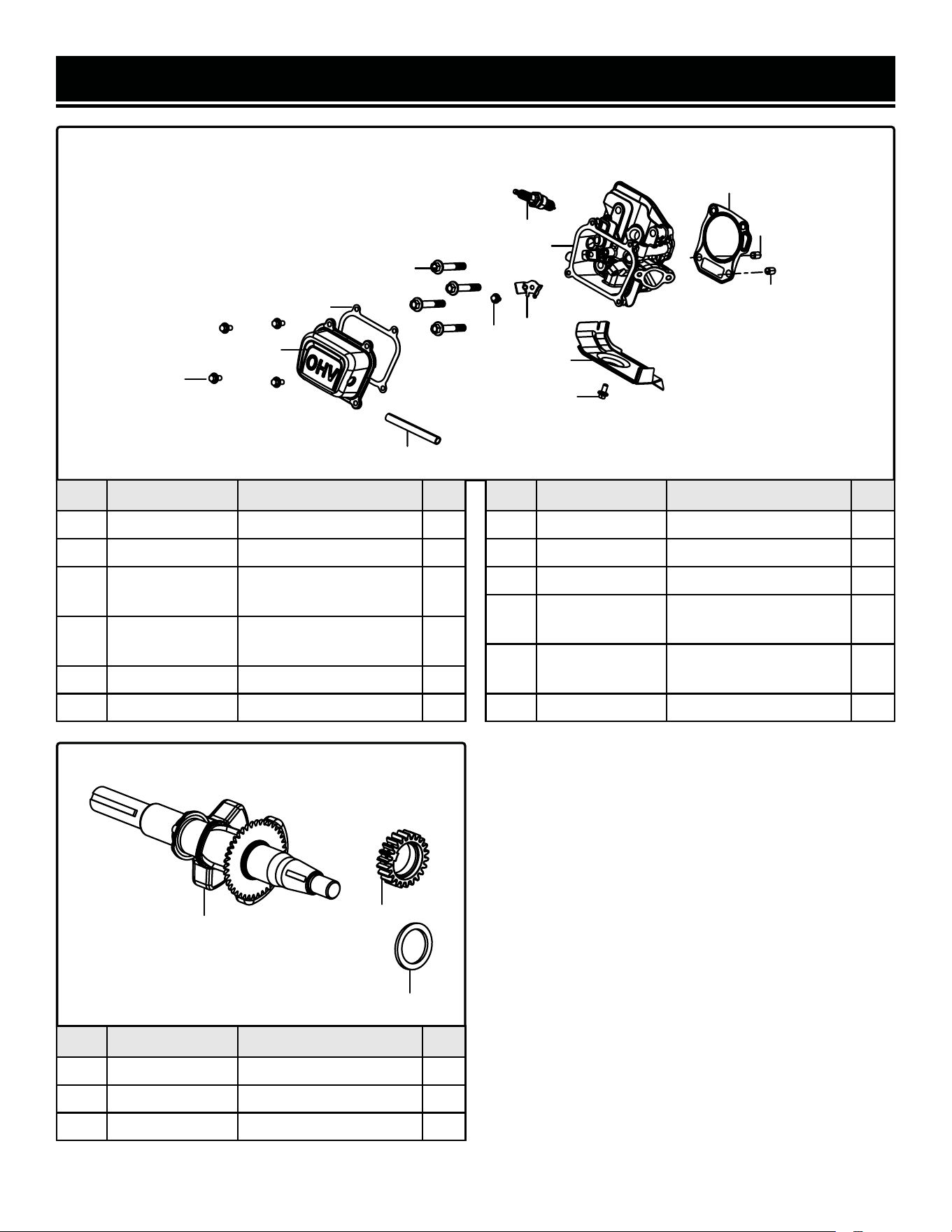
3-1 SB209E-0301 Bolt, M6x12 5
3-2 SB209E-0302 Cylinder Head Cover 1
3-3 SB209E-0303
Cylinder Head Cover
Gasket
1
3-4 SB209E-0304
Cylinder Head Bolt,
M8x60
4
3-5 SB209E-0305 Cylinder Head Assembly 1
3-6 SB209E-0306 Cylinder Shroud 1
FIG. 3. CYLINDER HEAD COVER, SPARK PLUG
1
2
3
4
5
6
7
8
8
9
10
1
11
12
No. Part No. Description Qty.
3-7 SB209E-0307 Bolt, M6x10 1
3-8 SB209E-0308 Positioning Pin, Type A 2
3-9 SB209E-0309 Cylinder Head Gasket 1
3-10 56380i-0312
Cylinder Head Cover Pin
Limiting Plate
1
3-11 56310i-0104
Spark Plug, Torch F6TC
(NGK BP6ES)
1
3-12 SB209E-0312 Breather Tube 1
No. Part No. Description Qty.
4-1 SB209E-0401 Crankshat Assembly 1
4-2 SB209E-0402 Flat Washer 1
4-3 SB209E-0403 Timing Drive Gear 1
FIG. 4. CRANKSHAFT
1
3
2
33
EXPLODED VIEW & PARTS LIST
No. Part No. Description Qty.
5-1 SB209E-0501 Piston Ring Set 1
5-2 SB209E-0502 Piston Pin Clip 2
5-3 SB209E-0503 Piston 1
5-4 SB209E-0504 Piston Pin 1
5-5 SB209E-0505 Connecting Rod 1
FIG. 5. PISTON RING SET,
CONNECTING ROD
FIG. 6. VALVE TRAIN, CAMSHAFT
No. Part No. Description Qty.
6-1 SB209E-0601 Camshaft Assembly 1
6-2 SB209E-0602 Valve Set 1
6-3 56310i-0603 Seal Guide 1
6-4 56310i-0604 Valve Spring 2
6-5 SB209E-0605 Valve Spring Seat 2
6-6 56310i-0606 Valve Locking Clamp 4
6-7 SB209E-0607 Valve Tappet 2
6-8 SB209E-0608 Valve Lifter 2
6-9 56380i-0610
Rocker Shaft
Subassembly
2
6-10 56380i-0609
Valve Rocker
Subassembly
2
5
3
4
2
2
1
1
2
3
4
4
5
5
6
6
8
7
9
8
7
9
10
10
No. Part No. Description Qty.
7-1 SB209E-0701 Shroud 1
7-2 SB209E-0702 Bolt, M6x12 4
7-3 SB209E-0703 Recoil Starter Assembly 1
7-4 SB209E-0704 Bolt, M6x8 3
FIG. 7. RECOIL STARTER
1
2
3
4
34
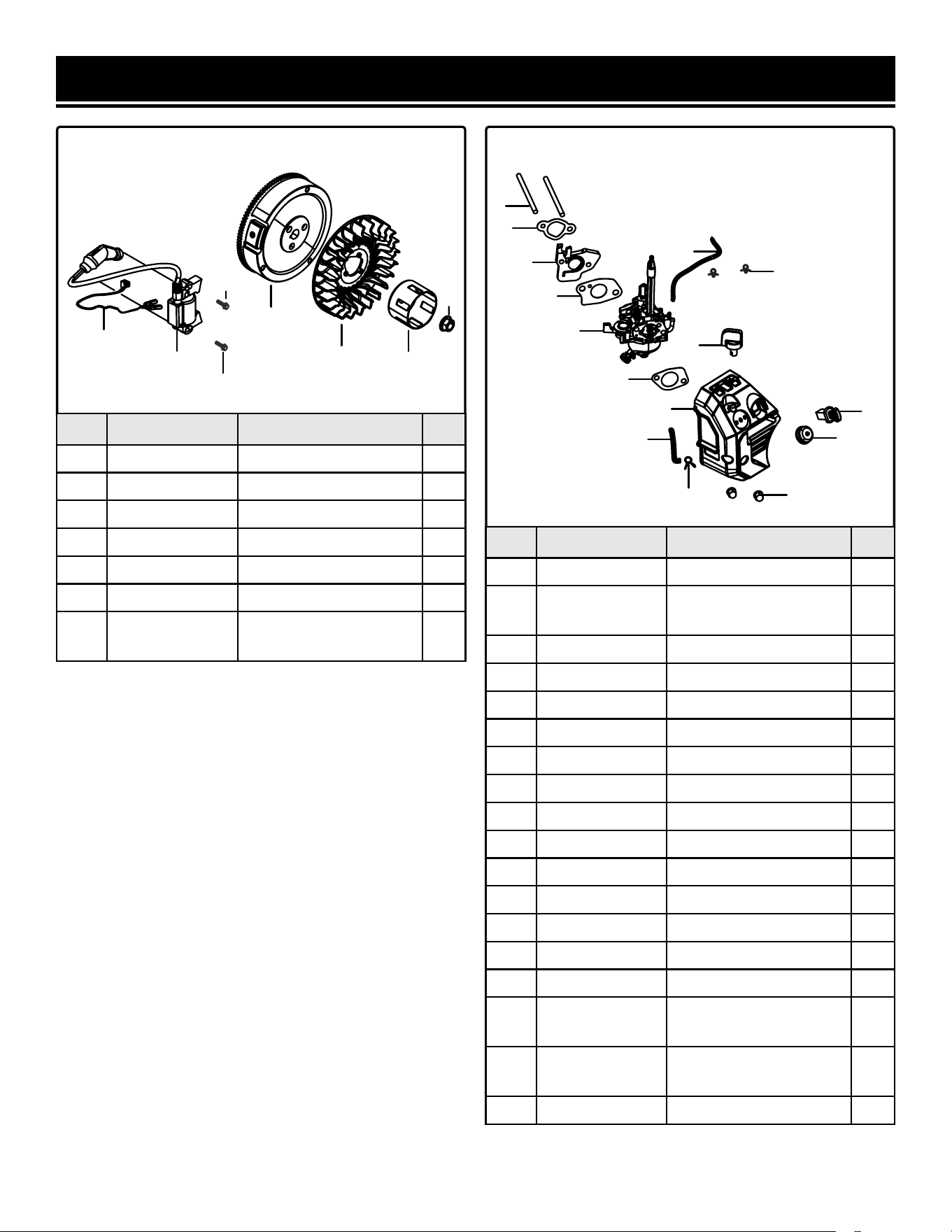
EXPLODED VIEW & PARTS LIST
No. Part No. Description Qty.
8-1 56310i-1101 Flywheel Nut, M14-1.5 1
8-2 SB209E-0802 Starter Pulley 1
8-3 SB209E-0803 Impeller 1
8-4 SB209E-0804 Flywheel 1
8-5 SB209E-0805 Bolt, M6x25 2
8-7 SB209E-0806 Ignition Coil 1
8-8 SB209E-0807
Ignition Coil Grounding
Wire
1
FIG. 8. FLYWHEEL, IGNITION COIL FIG. 9. CARBURETOR
No. Part No. Description Qty.
9-1 SB209E-0901 Stud Bolt, M6x96 2
9-2 56380i-0801
Carburetor Insulator
Gasket
1
9-3 SB209E-0903 Carburetor Insulator 1
9-4 SB209E-0904 Carburetor 1
9-5 GN400i-1101 Air Filter Gasket 1
9-6 SB209E-0906 Primer Tube 1
9-7 SB209E-0907 Knob 1
9-8 SB209E-0908 Air Filter 1
9-9 SB209E-0909 Fuel Tube 1
9-10 SB209E-0910 Engine Switch 1
9-11 SB209E-0911 Primer Button 1
9-12 SB209E-0912 Nut, M6 2
9-13 SB209E-0913 Hose Clamp 1
9-14 56380i-0803 Carburetor Gasket 1
9-15 SB209E-0915 Hose Clamp 2
N.P. SB209E-HA36
High-Altitude Kit,
3000 - 6000 ft
N/A
N.P. SB209E-HA68
High-Altitude Kit,
6000 - 8000 ft
N/A
N.P. SB209E-0910-1 Engine Key 1
1
2
3
4
5
5
6
7
1
2
3
4
5
6
7
8
9
10
11
12
13
14
15
35
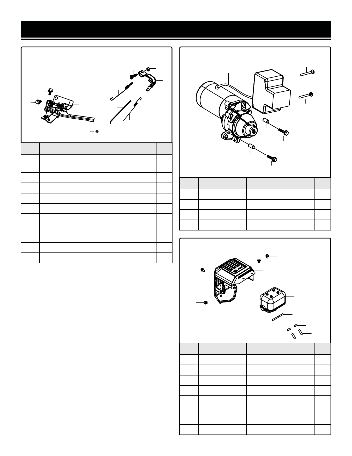
EXPLODED VIEW & PARTS LIST
No. Part No. Description Qty.
10-1 SB209E-1001
Throttle Control
Assembly
1
10-2 SB209E-1002 Throttle Spring 1
10-3 SB209E-1003 Governor Rod 1
10-4 SB209E-1004 Governor Spring 1
10-5 SB209E-1005 Governor Bracket 1
10-6 SB209E-1006 Bolt M6x10 2
10-7 SB209E-1007
Governor Support Bolt,
M6
1
10-8 SB209E-1008 Nut, M6 1
10-9 SB209E-1009 Hose Clamp 2
FIG. 10. THROTTLE ASSEMBLY FIG. 11. STARTER MOTOR
No. Part No. Description Qty.
11-1 SB209E-1101 Starter Motor Assembly 1
11-2 SB209E-1102 Screw, M4x50 2
11-3 SB209E-1103 Bolt, M6x32 2
11-4 SB209E-1104 Positioning Pin 2
1
6
6
5
7
8
2
3
4
9
2
2
1
3
3
4
4
FIG.12 MUFFLER ASSEMBLY
No. Part No. Description Qty.
12-1 SB209E-1201 Muffler Cover 1
12-2 SB209E-1202 Muffler Assembly 1
12-3 56380i-1106 Gasket, Exhaust Outlet 1
12-4 SB209E-1204 Nut M8 2
12-5 SB209E-1205
Stud Bolt (BM=1.5D)
M8x34
2
12-6 SB209E-1206 Bolt, M6x20 1
12-7 SB209E-1207 Bolt, M6x12 3
1
2
3
4
5
6
7
7
36
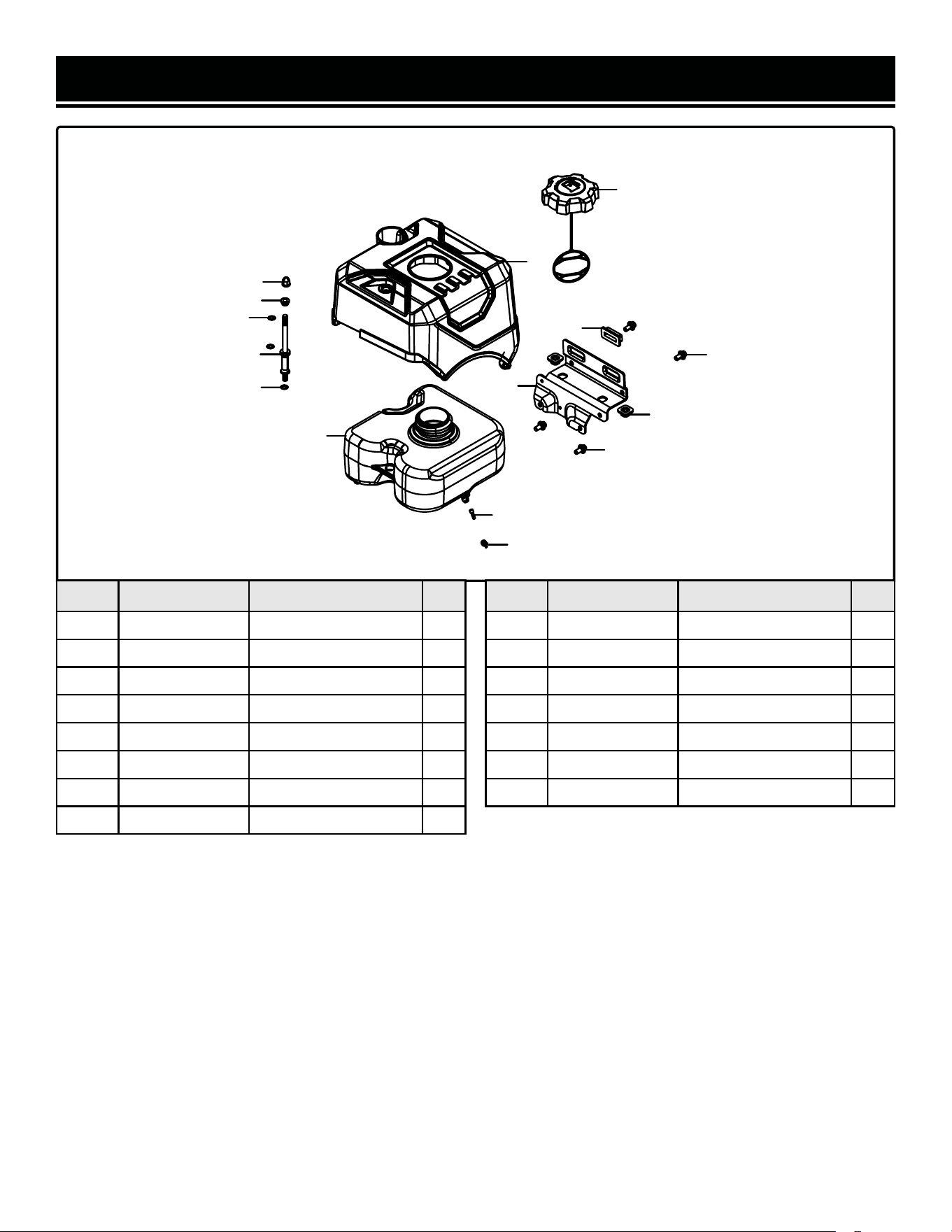
No. Part No. Description Qty.
13-1 SB209E-1301 Fuel Tank Cap 1
13-2 SB209E-1302 Fuel Tank Cover 1
13-3 SB209E-1303 Fuel Tank Gasket 2
13-4 SB209E-1304 Fuel Tank Frame 1
13-5 SB209E-1305 Fuel Tank 1
13-6 SB209E-1306 Support Bolt, M6x14 1
13-7 SB209E-1307 Cap Nut, M6 1
13-8 SB209E-1308 Bracket Gasket 2
FIG. 13. FUEL TANK ASSEMBLY
1
2
3
4
5
6
7
8
9
10
11
12
13
14
15
EXPLODED VIEW & PARTS LIST
No. Part No. Description Qty.
13-9 SB209E-1309 Bolt, M8x16 2
13-10 SB209E-1310 Bushing 1
13-11 SB209E-1311 Bolt, M6x12 2
13-12 SB209E-1312 Washer 1
13-13 SB209E-1313 Washer 2
13-14 SB209E-1314 Fuel Tank Filter 1
13-15 SB209E-1315 Clamp 1
37
EXPLODED VIEW & PARTS LIST
No. Part No. Description Qty.
14-1 SB209E-1401 Nut, M10 1
14-2 SB209E-1402 Pulley Assembly 1
14-3 SB209E-1403
Drive Belt, HTD-740-
5M-15
1
14-4 SB209E-1404 Shifting Fork 1
14-5 SB209E-1405 Pin 2
14-6 SB209E-1406 Washer 1
14-7 SB209E-1407 Housing 1
14-8 SB209E-1408 Drive Housing 1
14-9 SB209E-1409
Ball Bearing, 6203
NR-2RS
2
14-10 SB209E-1410 Washer 1
14-11 SB209E-1411 Nut, M10 1
14-12 SB209E-1412 Wheel 2
14-13 SB209E-1413 Wheel Bushing 2
14-14 SB209E-1414 Wheel Axle Bushing 2
14-15 SB209E-1415 Circlip 1
14-16 SB209E-1416 Axle 1
FIG. 14. DRIVE HOUSING ASSEMBLY
No. Part No. Description Qty.
14-17 SB209E-1417 Driven Gear 1
14-18 SB209E-1418
Locking Screw,
M6x12
5
14-19 SB209E-1419 Rear Cover 1
14-20 SB209E-1420 Nut, M8 1
14-21 SB209E-1421 Connecting Plate 1
14-22 SB209E-1422
Locking Screw,
M8x16
4
14-23 SB209E-1423 Pin 2
14-24 SB209E-1424 Bolt, M8x16 1
14-25 SB209E-1425 Washer 1
14-26 SB209E-1426 Tension Spring 1
14-27 SB209E-1427
Friction Disc
Assembly
1
14-28 SB209E-1428 Bolt M6x12 3
14-29 SB209E-1429
Clutch Cable, Self
Propulsion
1
14-30 SB209E-1430 Clutch Cable, Auger 1
14-31 SB209E-1431 Pin Shaft 1
38
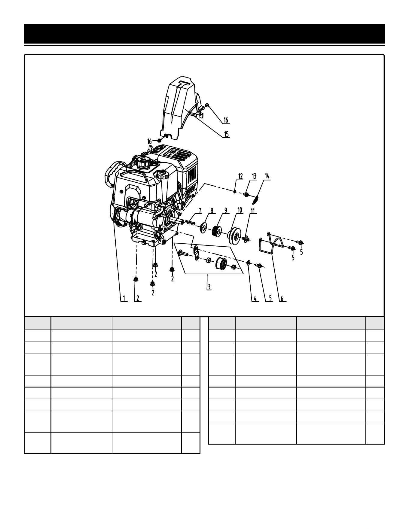
EXPLODED VIEW & PARTS LIST
No. Part No. Description Qty.
15-1 SB209E-1501ASM Engine Assembly 1
15-2 SB209E-1502 Nut, M8 4
15-3 SB209E-1503
Tensioner Pulley
Assembly
1
15-4 SB209E-1504 Gasket 1
15-5 SB209E-1505 Bolt, M8x16 3
15-6 SB209E-1506 Drive Belt Guard 1
15-7 SB209E-1507
Flat Key,
48x4.78x4.78
1
15-8 SB209E-1508
Timing Pulley
Adjusting Gasket
1
FIG. 15. ENGINE, BELT PULLEY ASSEMBLY
No. Part No. Description Qty.
15-9 SB209E-1509 Driving Timing Pulley 1
15-10 SB209E-1510 Driving Auger Pulley 1
15-11 SB209E-1511
Bolt and Washer
Assembly, M8x20
1
15-12 SB209E-1512 Spring Washer, 8mm 1
15-13 SB209E-1513 Bolt, M8x12 1
15-14 SB209E-1514 Tension Spring 1
15-15 SB209E-1515 Belt Cover 1
15-16 SB209E-1516
Locking Screw,
M6x12
2
39
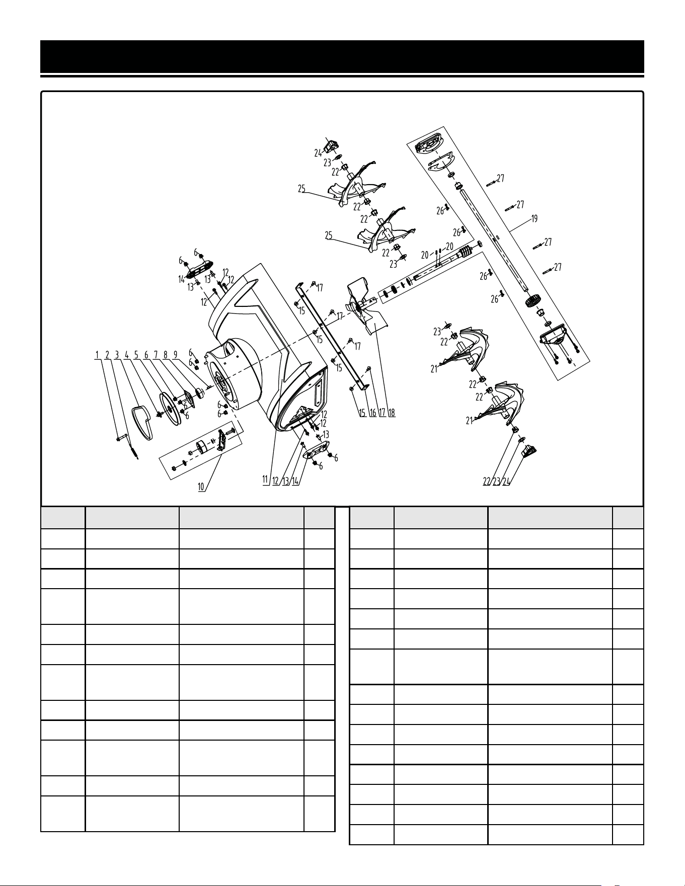
EXPLODED VIEW & PARTS LIST
No. Part No. Description Qty.
16-1 SB209E-1601 Bolt, M8x12 1
16-2 SB209E-1602 Auger Tension Spring 1
16-3 SB209E-1603 Auger Belt, 4LXA727 1
16-4 SB209E-1604
Bolt and Washer
Assembly, M8x20
1
16-5 SB209E-1605 Driven Pulley, Auger 1
16-6 SB209E-1606 Nut, M8 11
16-7 SB209E-1607
Worm Gear Bearing
Seat
1
16-8 SB209E-1608 Bearing, UC204 1
16-9 SB209E-1609 Flat Key, 20x6x6 1
16-10 SB209E-1610
Tension Wheel
Assembly, Auger
1
16-11 SB209E-1611 Auger Housing 1
16-12 SB209E-1612
Self-tapping Screw,
ST6.3x25
6
FIG. 16. AUGER HOUSING
No. Part No. Description Qty.
16-13 SB209E-1613 Bolt, M8x20 4
16-14 SB209E-1614B Skid Plate 2
16-15 SB209E-1615 Nut, M8 4
16-16 SB209E-1616 Scraper Bar 1
16-17 SB209E-1617 Bolt, M8x16 4
16-18 SB209E-1618 Impeller 1
16-19 SB209E-1619
Gearbox and Auger
Axle Assebly
1
16-20 SB209E-1620 Shaft Pin 2
16-21 SB209E-1621 Right Auger 2
16-22 SB209E-1622 Bushing 8
16-23 SB209E-1623 Washer 4
16-24 SB209E-1624 Bearing Seat 2
16-25 SB209E-1625 Left Auger 2
16-26 SB209E-1626 Bowtie Clip 4
16-27 SB209E-1627 Shear Pin 4
40
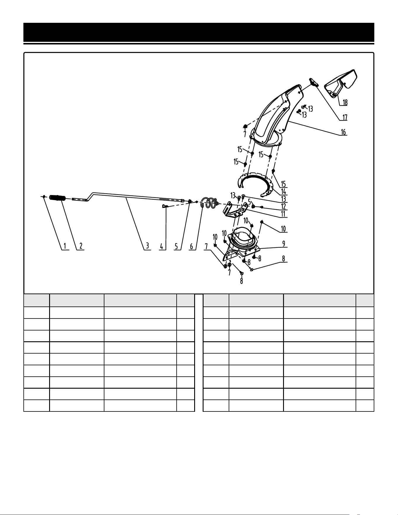
EXPLODED VIEW & PARTS LIST
No. Part No. Description Qty.
17-1 SB209E-1701 Shaft Circlip, 10mm 1
17-2 SB209E-1702 Handle 1
17-3 SB209E-1703 Rod 1
17-4 SB209E-1704 Pin 1
17-5 SB209E-1705 Rotator Bushing 2
17-6 SB209E-1706 Rotator Screw 1
17-7 SB209E-1707 Nut, M8 3
17-8 SB209E-1708 Bolt, M6x16 4
17-9 SB209E-1709 Base 1
FIG. 17. CHUTE ASSEMBLY
No. Part No. Description Qty.
17-10 SB209E-1710 Nut, M6 4
17-11 SB209E-1711 Bracket 1
17-12 SB209E-1712 Locking Screw, M6x12 1
17-13 SB209E-1713 Bolt, M8x20 4
17-14 SB209E-1714 Chute Base Plate 1
17-15 SB209E-1715 Bolt, M6x20 4
17-16 SB209E-1716 Chute 1
17-17 SB209E-1717 Lock Nut, M8 1
17-18 SB209E-1718 Chute Deflector Plate 1
41
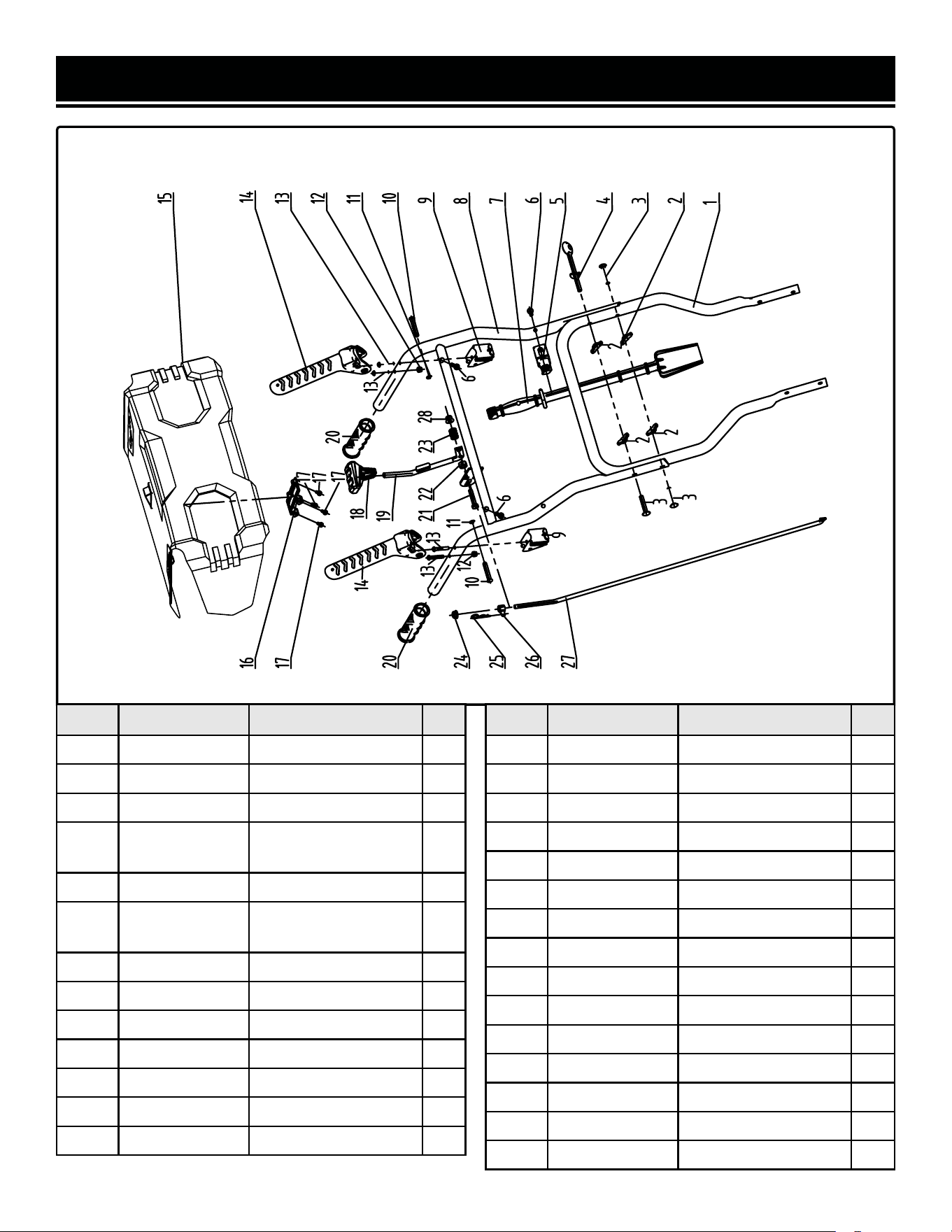
EXPLODED VIEW & PARTS LIST
No. Part No. Description Qty.
18-1 SB209E-1801 Lower Handle 1
18-2 SB209E-1802 Lock Nut, M8 4
18-3 SB209E-1803 Bolt, M8x45 3
18-4 SB209E-1804
Rotator Mounting
Bracket
1
18-5 SB209E-1805 Shovel Bracket 1
18-6 SB209E-1806
Self-tapping Screw,
ST6.3x25
3
18-7 SB209E-1807 Shovel Bracket 1
18-8 SB209E-1808 Upper Handle 1
18-9 SB209E-1809 Lever Mounting Seat 2
18-10 SB209E-1810 Pin Shaft 2
18-11 SB209E-1811 Circlip, 6mm 2
18-12 SB209E-1812 Nut, M6 2
18-13 SB209E-1813 Bolt, M6x37 4
FIG. 18. HANDLE
No. Part No. Description Qty.
18-14 SB209E-1814 Lever 2
18-15 SB209E-1815 Panel 1
18-16 SB209E-1816 Gear Indicator Seat 1
18-17 SB209E-1817 Screw, ST4.8x13 4
18-18 SB209E-1818 Shift Lever Grip 1
18-19 SB209E-1819 Shift Lever Rod 1
18-20 SB209E-1820 Handle Grip 2
18-21 SB209E-1821 Bolt, M8x40 1
18-22 SB209E-1822 Nut, M10 1
18-23 SB209E-1823 Pressure Spring 1
18-24 SB209E-1824 Nut, M8 1
18-25 SB209E-1825 Pin 1
18-26 SB209E-1826 Adjusting Nut, M8 1
18-27 SB209E-1827 Shift Lever 1
18-28 SB209E-1828 Nut, M8 1
42

WARRANTY STATEMENT
WEN Products is committed to building tools that are dependable for years. Our warranties are consistent with this
commitment and our dedication to qualit
y.
LIMITED WARRANTY OF WEN PRODUCTS FOR HOME USE
GRE
AT LAKES TECHNOLOGIES, LLC (“Seller”) warrants to the original purchaser only, that all WEN
consumer
power tools will be free from defects in material or workmanship during personal use for a period of two (2) years
used
for professional or commercial use. Purchaser has 30 days from the date of purchase to report missing or
damaged parts.
SELLER’S
SOLE OBLIGATION AND YOUR EXCLUSIVE REMEDY under this Limited Warranty and, to the extent per-
mitted
by law, any warranty or condition implied by law, shall be the replacement of parts, without charge, which a
re
defective
in material or workmanship and which have not been subjected to misuse, alteration, careless handling,
misrepair
, abuse, neglect, normal wear and tear,
improper maintenance, or other conditions adversely affecting the
Product
or the component of the Product, whether by accident or intentionally, by persons other than Seller. To
make
a claim under this Limited Warranty, you must make sure to keep a copy of your proof of purchase that
clearly
-
dor
of Great Lakes Technologies, LLC. Purchasing through third party vendors, including but not limited to garage
sales,
pawn shops, resale shops, or any other secondhand merchant, voids the warranty included with this
product.
Contact [email protected] or 1-847-429-9263 with the following information to make arrangements:
your
shipping address, phone number, serial number, required part numbers, and proof of purchase. Damaged
or
defective parts and products may need to be sent to WEN before the replacements can be shipped out.
-
turning
a product for warranty service, the shipping charges must be prepaid by the purchaser. The product
must
be
shipped in its original container (or an equivalent), properly packed to withstand the hazards of shipment. The
product
must be fully insured with a copy of the proof of purchase enclosed. There must also be a description of
the
will be returned and shipped back to the pur
chaser at no charge for addresses within the contiguous United States.
THIS
LIMITED WARRANTY DOES NOT APPLY TO ITEMS THAT WEAR OUT FROM REGULAR USAGE OVER TIME,
INCLUDING
BELTS, BRUSHES, BLADES, BATTERIES, ETC. ANY IMPLIED WARRANTIES SHALL BE LIMITED IN
DUR
ATION TO TWO (2) YEARS FROM DATE OF PURCHASE. SOME STATES IN THE U.S. AND SOME CANADIAN
PROVINCES
DO NOT ALLOW LIMITATIONS ON HOW LONG AN IMPLIED WARRANTY LASTS, SO THE ABOVE LIMI-
TAT
ION MAY NOT APPLY TO YOU.
IN
NO EVENT SHALL SELLER BE LIABLE FOR ANY INCIDENTAL OR CONSEQUENTIAL DAMAGES (INCLUDING
BUT
NOT LIMITED TO LIABILITY FOR LOSS OF PROFITS) ARISING FROM THE SALE OR USE OF THIS PRODUCT.
SOME ST
ATES IN THE U.S. AND SOME CANADIAN PROVINCES DO NOT ALLOW THE EXCLUSION OR LIMITAT
ION
OF
INCIDENTAL OR CONSEQUENTIAL DAMAGES, SO THE ABOVE LIMITATION OR EXCLUSION MAY NOT APPLY
TO YOU.
THIS
LIMITED WARRANTY GIVES YOU SPECIFIC LEGAL RIGHTS, AND YOU MAY ALSO HAVE OTHER RIGHTS
WHICH
VARY FROM STATE TO STATE IN THE U.S., PROVINCE TO PROVINCE IN CANADA AND FROM COUNTRY
TO COUNT
RY.
THIS
LIMITED WARRANTY APPLIES ONLY TO ITEMS SOLD WITHIN THE UNITED STATES OF AMERICA, CANA-
DA
AND THE COMMONWEALTH OF PUERTO RICO. FOR WARRANTY COVERAGE WITHIN OTHER
COUNTRIES,
CONT
ACT THE WEN CUSTOMER SUPPORT LINE. FOR WARRANTY PARTS OR PRODUCTS REPAIRED UNDER
W
ARRANTY SHIPPING TO ADDRESSES OUTSIDE OF THE CONTIGUOUS UNITED STATES, ADDITIONAL
SHIPPING
CHARGES MAY APPLY.
43

THANKS FOR
REMEMBERING
V. 2025.04.23
