Before using this product,
carefully read
and properly keep this manual.
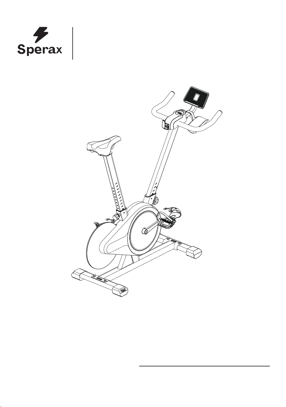
Sperax BIKE
Product Manual
Sperax BIKE
Model :YS-BA3, SPX-DC001, YS-BA5
FCC ID:2A3YB-YS-BA3

01
Catalogue
02
03
04
07
15
17
19
22
24
25
1. Product Parameters
2. mport
ant Safety Instructions
3. Installation Guide - List of Parts
4. Ins
tallation Guide
5. Fir
st Use(LED display usage instructions)
6. APP usag
e instructions
7. Ho
w to Adjust Bike
8. Ho
w to Determine Correct Riding Posture
9. Se
at Cushion Angle Adjustment
10.Warm up

Tablet (mobile phone) holder size
Supporting software version
Resistance system
Drive mode
Power supply
Connection mode of sensing system
Height limit
Rated maximum load
Net weight
Gross weight
Overall dimensions
Maximum tablet width: 10.1-inch
IOS 12.0 or higher, Android 7.0 or higher(inclusive)
Magnetron resistance system
Belt drive
AA battery
Bluetooth
61 ~ 78inches
300lbs
41.8lbs
47.3lbs
(Length) 44.48inches × (Width) 18.7inches × (Height) 40.94inches
Product Parameters
Routine Maintenance
1. Keep the cycling bike on a dry, ventilated and flat floor. If not used in a long time, the bike should be
covered to keep its body clean and tidy.
2. Wipe off sweat on the frame with cloth after exercise. Do not wipe the bike with wet cloth, in order to
avoid rusting.
3. Check the belt pulley for cracks and misalignment, and adjust or replace the belt as needed.
Regularly clean the belt groove to prevent the belt from slipping out.
4. Always check the screws of all body parts for loosening or falling, and tighten or replace them in time.
5. Always check the resistance adjustment knob for loosening or falling. Check whether the resistance is
reasonable, so as to calibrate resistance in time.
6. Always check the screws of pedals and cranks for loosening, and tighten them in time.
7. Always check whether the saddle is loose and tighten it in time. Wipe the saddle with cotton cloth to
keep it dry.
02

Important Safety Instructions
Please read them carefully.
1. This product is for household use (Class H) and not medical fitness equipment.
2. This product must not be used for medical rehabilitation.
3. Keep children and pets away from this product. This product is for those over 16 years old only.
4. Never expose this product in a humid place. This product must not be used outdoor or in any
humid place.
5. Never use this product with inappropriate shoes or barefoot.
6. Use this product on a flat and clean ground.
7.Lift the rear tube and the roller on the front tube can move the product freely or be placed in a
suitable position.
8. If the product fails, stop using it immediately.
9. Check whether the bike for loosening or damage before each use.
10. Never stretch any object or body part into the openings of the bike.
11. When using the screen holder, ensure the device is centered to prevent it from falling off.
12. Do not modify this bike or use non-original accessories without permission.The casing must
be opened by professionals, in order to avoid damage.
13. Make sure that the saddle height adjustment knob is secured
correctly, and will not affect
motion during exercise.
14.Instructions for using the emergency brake: When you want to stop movement, press down on
the emergency brake until it stops.
15. Never turn pedals by hand,or touch any rotating mechanical part,otherwise personal injury
may be caused.
16. Get off the bike until flywheel/inertial wheel and pedals st
op rotating. Otherwise, severe
injuries may be caused due to control failure.
17.Do not touch the flywheel during exercise to avoid injury.
18. Wear professional cycling clothes or tight-fitting sportswear and sports shoes, and tighten foot
straps to avoid injury caused by pulling or entanglement by this product.
19.In order to facilitate entry, passing and emergency escape from the equipment, the minimum
space of the training equipment is: training equipment 600mm on one side and 600mm behind or
in front of the training equipment.
20. Incorrect or excessive training may cause injury.
21. Use this product according to the instructions in this manual. Warm up fully before exercise.
22. Keep the body hydrated as needed during riding.
23. Without the preliminary determination of baseline fitness level and medical certificate signed
by a doctor, never be engaged in high-speed or high-intensity sports. Before attempting any
high-intensity short sprints, pay attention to the body state and posture, and apply a controllable
speed.
24. In case of any discomfort such as dizziness or chest pain during exercise, stop exercising
immediately and go to a hospital for examination.
25. Those pregnant or with high blood pressure, heart disease, lumbar spondylosis or reduced
mobility must not use this product without the permission of doctors.
26. The weight of the user must not exceed the maximum load.
27. Carry out preventive maintenance regularly.
03
②
③
④
1
1
1
① 1
⑤
⑥
1
1
⑦
1
1
2×Hexagon dome head bolt
⑧
2×Hexagon socket head
screws and washers
2×Hexagon socket head
screws and washers
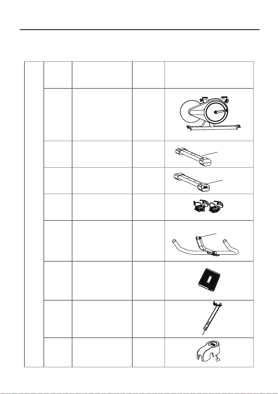
STEP 1: Check of parts
List of Parts
Parts List (Components List)
NO.
Name Quantity
Frame
Handlebar assembly
Pedal set left/right
Tablet (mobile phone)
holder
Front tube
Rear tube
Head tube
(Left)
(Right)
Figure
Installation Guide - List of Parts
Decorative cover
04
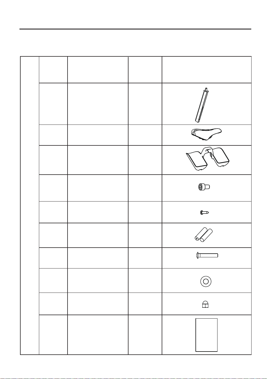
⑨
⑩
⑪
⑫
⑬
⑭
1
1
Seat
Bottle holder
1
Seat post
2
3
1
AA battery
Hexagon socket
head screw
Cross self
tapping nail
Parts List (Components List)
NO.
Name Quantity
Figure
Installation Guide - List of Parts
Instructions
Instructions
⑮
⑯
⑰
⑱
1
4
4
4
D8 flat spacer
Carriage bolt
Cap nut
05
A
B
C
1
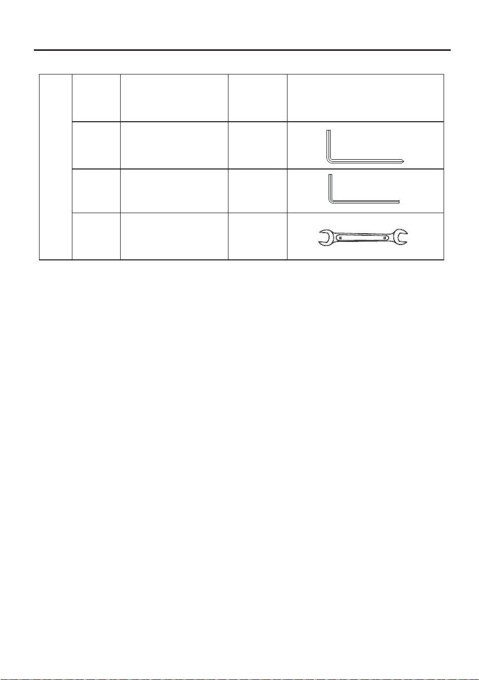
Installation Guide - List of Parts
NO.
Name Quantity
Figure
Accessories List (Tools List)
L-shaped cross head
hexagon wrench 6#
1
Open-ended wrench
*In order to facilitate assembly,
some fixing screws are pre-locked
on the corresponding parts at the factory. Please remove them
before installing the corresponding parts during assembly.
Spare parts are subject to actual conditions.
1
L-shaped hexagon
wrench 4#
06
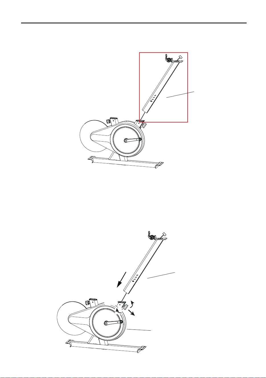
1. As shown in the picture, first pass the electronic meter wire through the head tube ⑦;
2. Rotate the rear column tightening knob in the left direction for 4-5 turns using
one hand, pull it out and hold it, align the head tube ⑦ with the opening of the frame①;
3.Stuff the excess wire into the head tube,insert it into the frame①, and adjust it to the
required position. Ensure the scale aligns with the top surface of the tube and snaps
into the slot. Then release the knob, gently pull the column up and down to allow the
spring to return automatically(a "click" sound indicates the knob has slid into the
column hole). Finally, tighten the knob to the right until it is fully secure.
Installation Guide
STEP 1: Installation of head tube
Before installing the head
tube,please loosen the
handle to the left until
the head tube ⑦ can be
inserted, pull it outward
and hold it.
Pull
07
Tight
(Right)
Loose
(Left)
⑦
⑦
①
Installation Guide
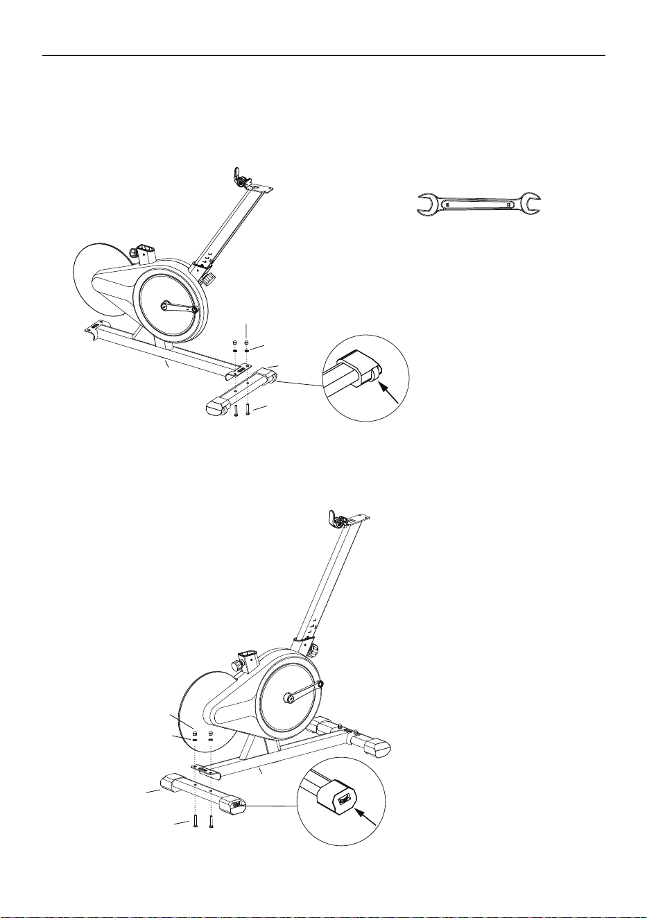
STEP 2: Installation of bottom tube
Pay attention to distinguishing
between the front and rear
foot tubes. The front foot tube
comes with a moving pulley,
please place it outward.
Pay attention to distinguishing
between the front and rear
foot tubes, and the rear foot
tubes are equipped with foot
pad adjustment knobs.
②
①
⑰
⑯
⑮
①
⑰
⑯
⑮
③
Open-ended wrench(C)
1.Align the holes of the front tube ② with the holes at the bottom of the frame ①,
thread the carriage bolts⑮from the bottom of the front tube to connect the front
tube to the bottom of the front column, and at the top end, thread in the D8 flat
spacer ⑯ and cap nut ⑰, and then lock and tighten it up using an open-ended
wrench(D).
2.Align the holes of the rear tube ③ with the holes at the bottom of the frame ①,
thread the carriage bolts⑮from the bottom of the front tube to connect the front
tube to the bottom of the front column, and at the top end, thread in the D8 flat
spacer ⑯ and cap nut ⑰, and then lock and tighten it up using an open-ended
wrench(D).
08
Hexagon dome head bolt
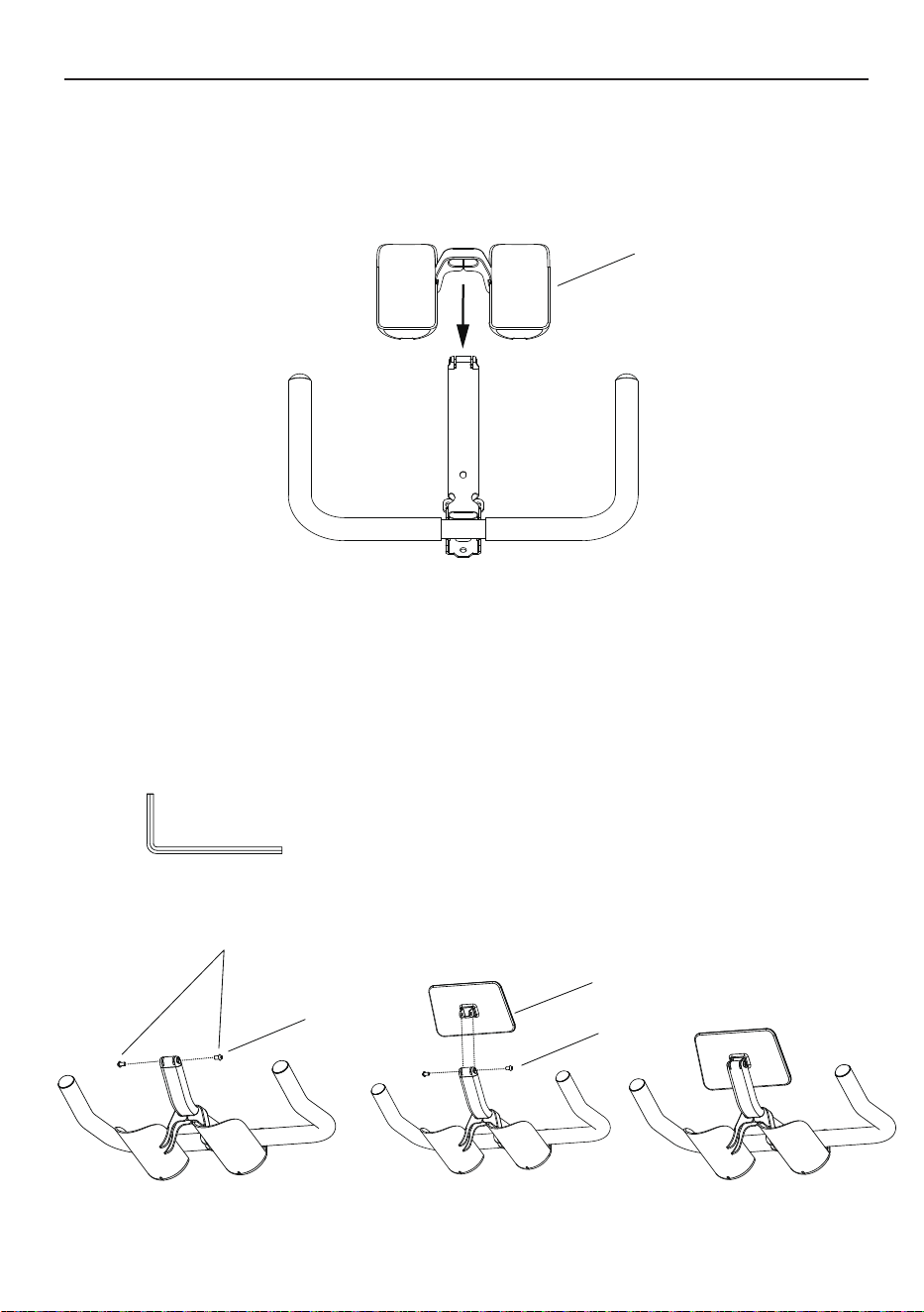
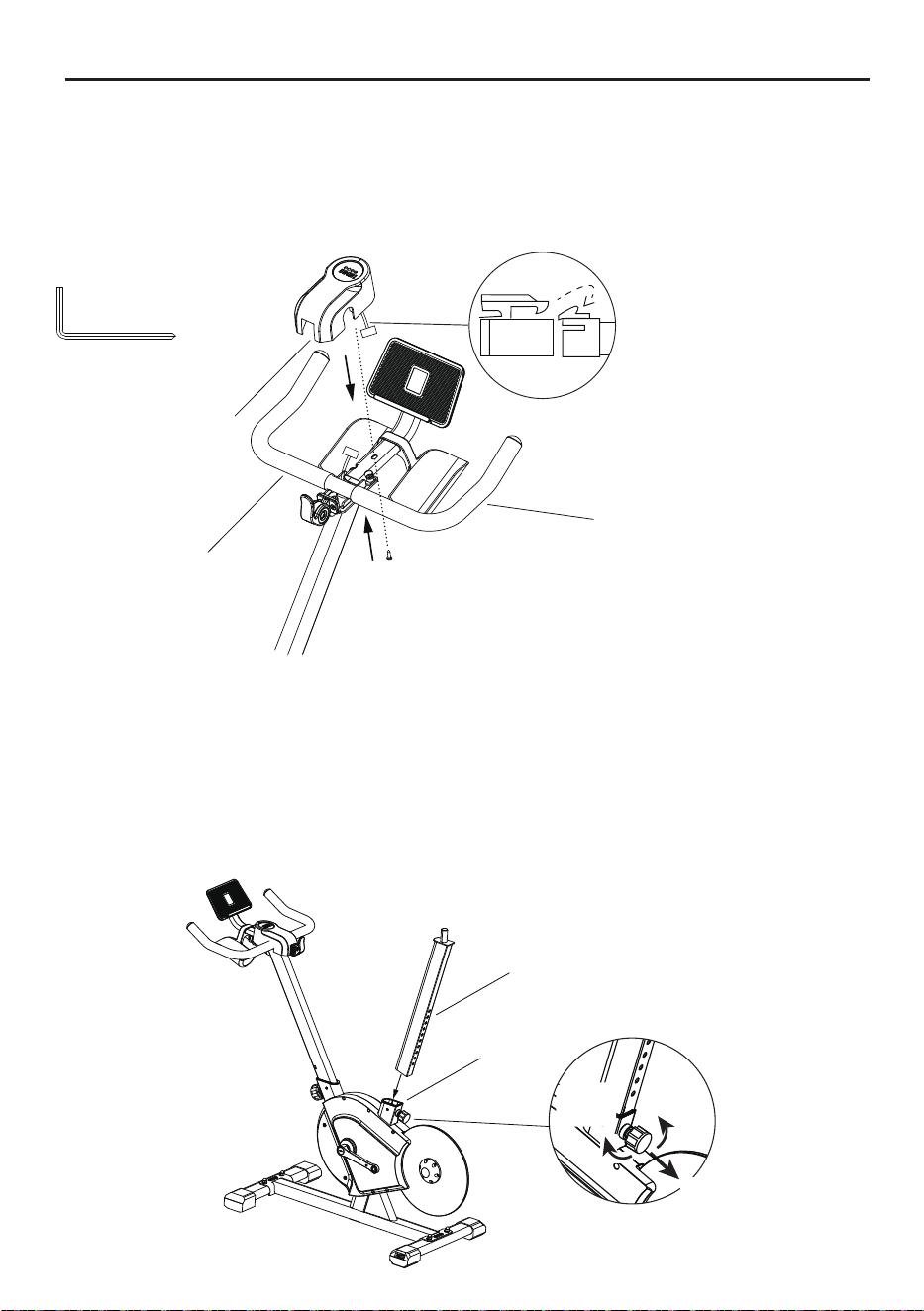
1. Remove two hexagon dome head bolt pre-installed on the handlebar
assembly ⑤ via the L-shaped hexagon wrench 4#(B).
2. Insert the tablet (mobile phone) holder ⑥ into the slot of the handlebar
assembly ⑤, manually fasten the hexagon dome head bolt into holes,
and lock them via the L-shaped hexagon wrench 4#(B).
Installation Guide
STEP 4: Installation of tablet (mobile phone) holder
L-shaped hexagon wrench 4#(B)
⑪
STEP 3:Installation of bottle holder
⑥
⑤
⑤
1. Take out the water bottle cage ⑪ and open it with a little force. Then insert it
along the bracket tube at the front of the armrest assembly and install it to the
appropriate position.
09
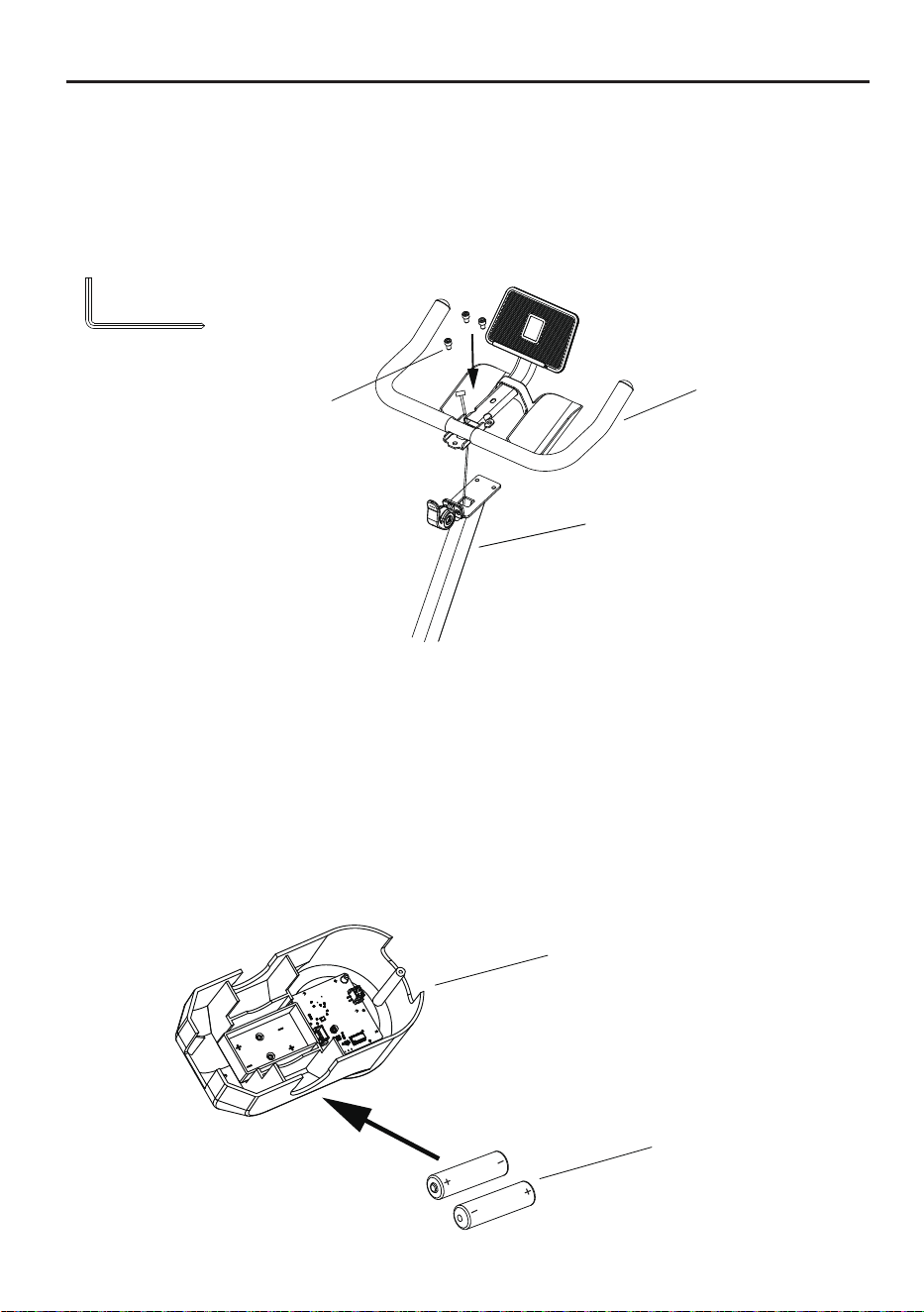
1. Align the battery ⑭ with the positive and negative poles of the card slot,
insert it into the battery slot, and then fasten the battery cover to complete
the installation. If you need to replace the battery, please remove the decorative
cover
⑧, take out the old battery, align the positive and negative poles of the new
battery with the positive and negative poles of the card slot, insert it into the
battery slot, then buckle the decorative cover
⑧
on the handlebar assembly ⑤,
and gently press lightly to secure.
1. Take out three hexagon sockethead screws
⑫ from the ziplock bag;
2. First pass the electronic meter wire through the handlebar assembly ⑤,
then align the handlebar assembly ⑤ with the hole at the connection of the
head tube ⑦,and finally turn the hexagon sockethead screws ⑫ in the direction
of the arrow,and use an
L-shaped cross head hexagon wrench 6#(A)
to tighten.
Installation Guide
STEP 6: Battery installation and dismantling
*Note:Do not let sweat and
other liquids come into contact
with electronic components,
which may cause damage to
the electronic components.
STEP 5: Installation of handlebar assembly
L-shaped cross head
hexagon wrench 6#(A)
⑧
⑭
⑦
⑫
⑤
10
STEP 7:Installation decorative cover
Installation Guide
L-shaped cross head
hexagon wrench 6#(A)
Align the port to connect to the
screen connection cable
* Please make sure that the
connection direction is correct.
Please do not connect it with
violence.
⑧
⑤
⑬
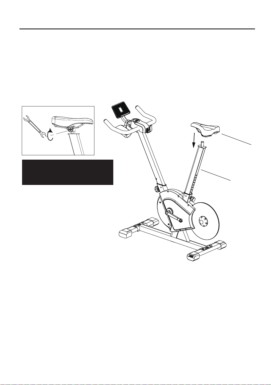
1. Rotate the rear column tightening knob in the left direction for 4-5 turns using
one hand, pull it out and hold it, align the seat post ⑨ with the opening of the frame①;
2.Insert it into the frame①, and adjust it to the required position. Ensure the scale
aligns with the top surface of the tube and snaps into the slot. Then release the knob,
gently pull the column up and down to allow the spring to return automatically
(a "click" sound indicates the knob has slid into the column hole). Finally, tighten the
knob to the right until it is fully secure;
STEP 8:Installation of seat post & seat
Loose
(Left)
Before installing the seat post ,
please loosen the knob to the left
until the seat post ⑨ can be inserted,
pull outward and hold.
Tight
(Right)
⑨
①
Pull
1.Insert the electronic meter cable port into the decorative cover ⑧,
then buckle the decorative cover ⑧ on the handlebar assembly ⑤,
and gently press lightly to secure.Finally, turn the cross self
tapping nail ⑬ in t
he direction of the arrow,and use an L-shaped cross head hexago
n wrench 6#(A)
to tighten.
11
Installation Guide
3.Remove the seat⑩ from the self-sealing bag;
4.Insert the seat ⑩ into the hole of the seat post ⑨, press the head of the seat
cushion downward with your hand, and adjust it to a more comfortable angle (it is
recommended to adjust the seat cushion head to tilt downward one step), and
use the open-end wrench (C) to wards lock the two nuts on the left and right sides
of the bottom in the direction of the arrow (the seat needs to be checked to see if
it is locked to avoid shaking during use).
Open-ended
wrench (C)
Note: Lock the nut in the clockwise
direction and loosen it in the
counterclockwise direction.
⑩
⑨
12
Installation Guide
Open-ended wrench(C)
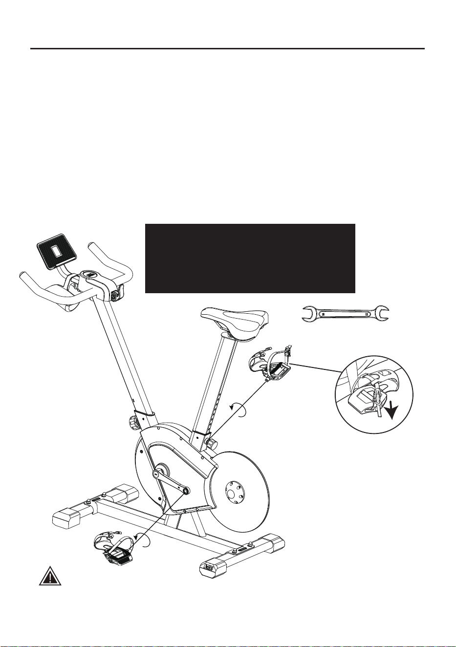
STEP 9: Pedal installation
Safety tips:
Reverse riding is not recommended, as it is likely to loosen pedals. After reverse riding,
check whether the pedals are locked, in order to avoid safety issues arising from loose pedals.
1. Take the pedals from the package.
2. Distinguish left and right pedals. The right pedal is marked blue “R”, and the
left pedal is marked red “L” (Pay attention to distinguish left and right pedals.
If they are not installed correctly, crank threads will be dama
ged!)
3. Stand behind the seat and face the handlebar. Install the right pedal on the right
crank, and ensure that the pedal is vertical to the crank mounting hole. Use an
open-ended wrench (C) to lock it toward the head direction. Install the left pedal to
the left crank, and ensure that the pedal is vertical to the crank mounting hole.
Use an open-ended wrench (C) to lock it toward the head direction.
Note: During installation, correspond the red mark on the crank to the red mark
on the pedal, and the blue mark on the crank to the blue mark on the pedal.
Do not mix up them!
Screw the pedal into the crank manually first, and
then tighten the pedal assemblies L/R ④ with the
open-ended wrench (C). (Note: The tightening
directions for both the left pedal and the right pedal
are towards the head direction.)
Left pedal
assembly ④
Right pedal
assembly ④
Note: Check whether the pedal
straps are tightened before riding.
Tighten them by pulling them down.
13
Installation Guide (For reference only, subject to the actual product)
Safety tips:
Please adjust the bike according to your own conditions before use;
and tighten the bike fastening knob.
Statement:
This manual contains the functional introduction and operating instructions as much as
possible when printed.
With the continuous improvement of hardware and software and optimization of design, this
manual may be inconsistent with the purchased product.
In case of any discrepancy in appearance, interface and color, the actual product shall prevail.
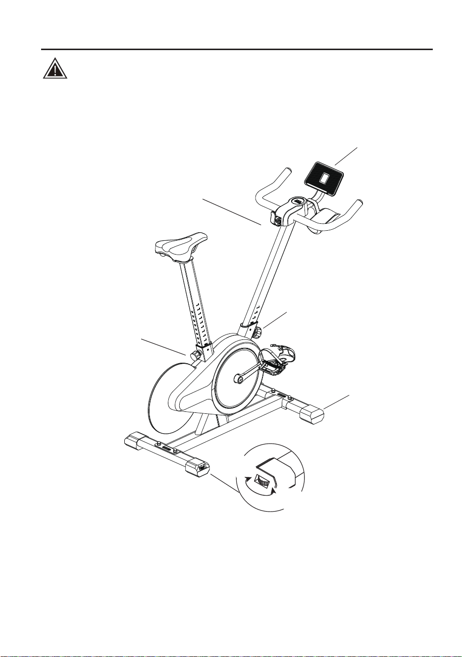
If used, the screen bracket
should be set up at the center.
Resistance knob
(Adjust the resistance as needed,
press it to brake in an emergency.)
Front column tightening knob
(Adjust the armrest height)
Rear column tightening knob
(Adjust the saddle height)
Movable pulley
Bike level
adjustment pad
High
(Right)
Low
(Left)
14
First Use(LED display usage instructions)
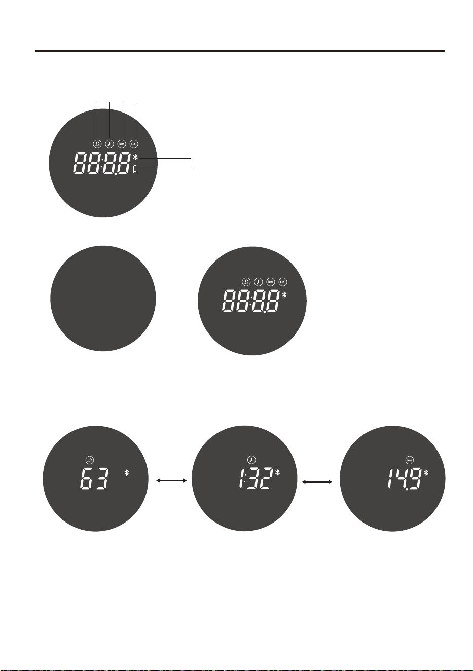
LED display instructions:
LED display usage instructions:
2.Spin the bike for three laps in 4.5S in the standby state, the interface jumps to the
movement state displaying the pedaling frequency, exercise time, and mileage data
alternatively;
3.Stop the exercise in the movement state for 5S to enter the pause state;
the display interface jumps to the time interface;
4.Continue biking in the pause state to resume the bike to the movement state;
5.If the bike remains in pause mode for 60S, it will enter the data summary interface.
Bluetooth
Power
Calorie
Time
Pedaling
frequency
Distance
Power off
Pedaling frequency page
Time page
Distance page
Automatic
switching
Automatic
switching
1.Spin the bike for one lap to turn on and
enter the standby interface (Automatically
shut down after 30S of stopping ridi
ng.)
15

First Use(LED display usage instructions)
LED display instructions:
Icon display:
Low battery: the battery icon on the digital tube flashes red.
Bluetooth icon: Bluetooth connected, icon is always on;
Bluetooth not connected, the icon flashes.
Automatic
switching
The data settlement interfaces end the display
after 15S and is switched to the standby mode,
and then the bike is shut down in 30S.
16

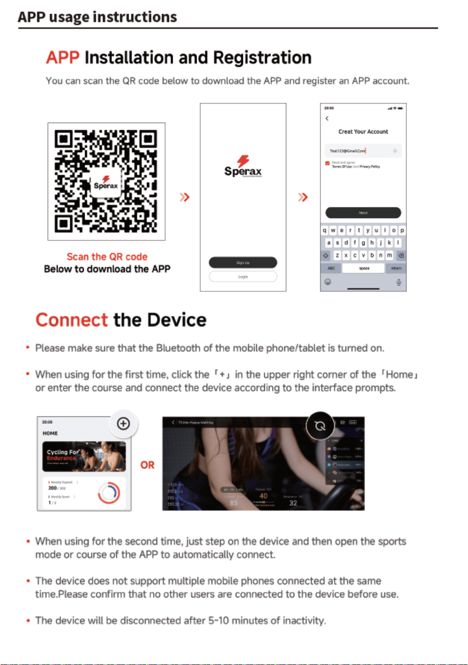
APP usage instructions
17
18
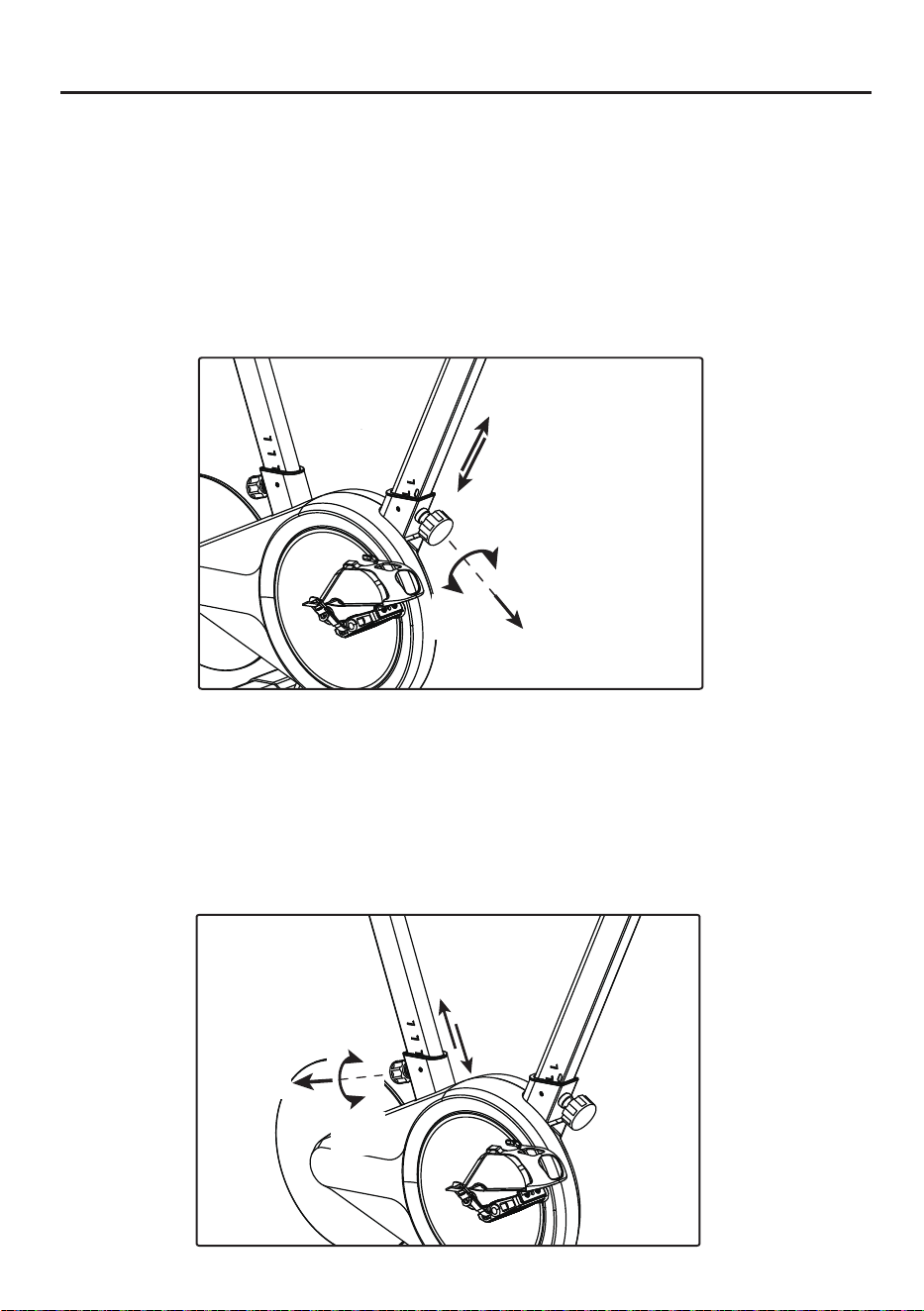
How to Adjust Bike
1. Handlebar height adjustment:
Rotate the front column knob in the left direction for 4-5 turns using one hand,
pull it out and hold it. With the other hand, hold and lift up (or press down)
the handlebar to the desired position, then release the knob, gently pull the
column up and down, so that the spring can automatically reset (the “click”
sound indicates that the knob has slipped into the column slot hole) Finally,
turn the knob to the right to the tightest position.
Rotate the front column knob in the left direction for 4-5 turn
s using one hand,
pull it out and hold it. With the other hand, hold and lift up
(or press down)
the seat to the desired position, then release the knob, gently pull the column
up and down, so that the spring can automatically reset (the “click” sound
indicates that the knob has slipped into the column slot hole) Finally,
turn the knob to the right to the tightest position.
2. Saddle height adjustment:
The head tube must not
exceed the STOP mark
during handlebar adjustment.
The head tube must
not exceed the STOP
mark during saddle
adjustment.
Pull
Tight
(Right)
Loose
(Left)
Loose
(Left)
Tight
(Right)
Pull
19
How to Adjust Bike
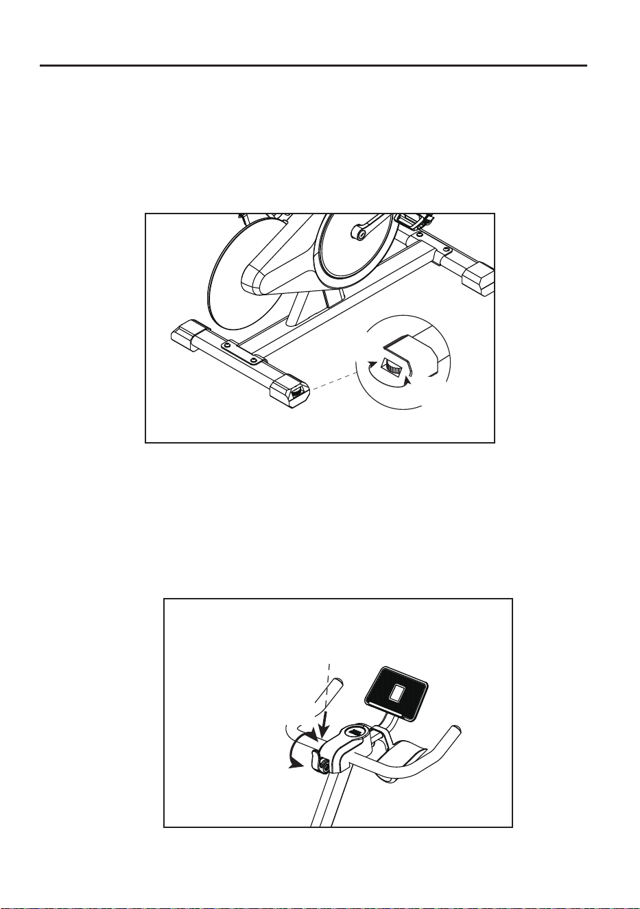
3. Bike level adjustment:
There are two adjustment pads at the bottom of the rear pedal tubes.
Screw these pads until the bike does not shake.
4.Knob adjustment:
When not in use, press the handle down to the bottom. When riding, lift the handle
up to the top (the resistance can be adjusted up or down according to riding needs).
When braking in an emergency or stopping movement, press the handle down to
the bottom, until it stops.
Press down
High
(Right)
Low
(Left)
Big
(Right)
Small
(Left)
20
How to Adjust Bike
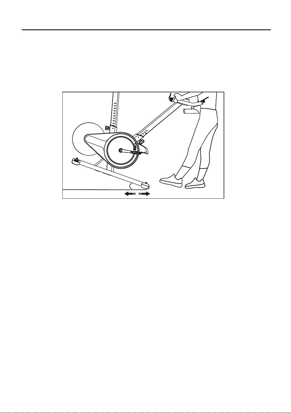
5. Bike level adjustment:
Pressing down on the armrest raises the foot tube by more than 25°,
and use the moving pulley to drag the dynamic bicycle.
25°
21
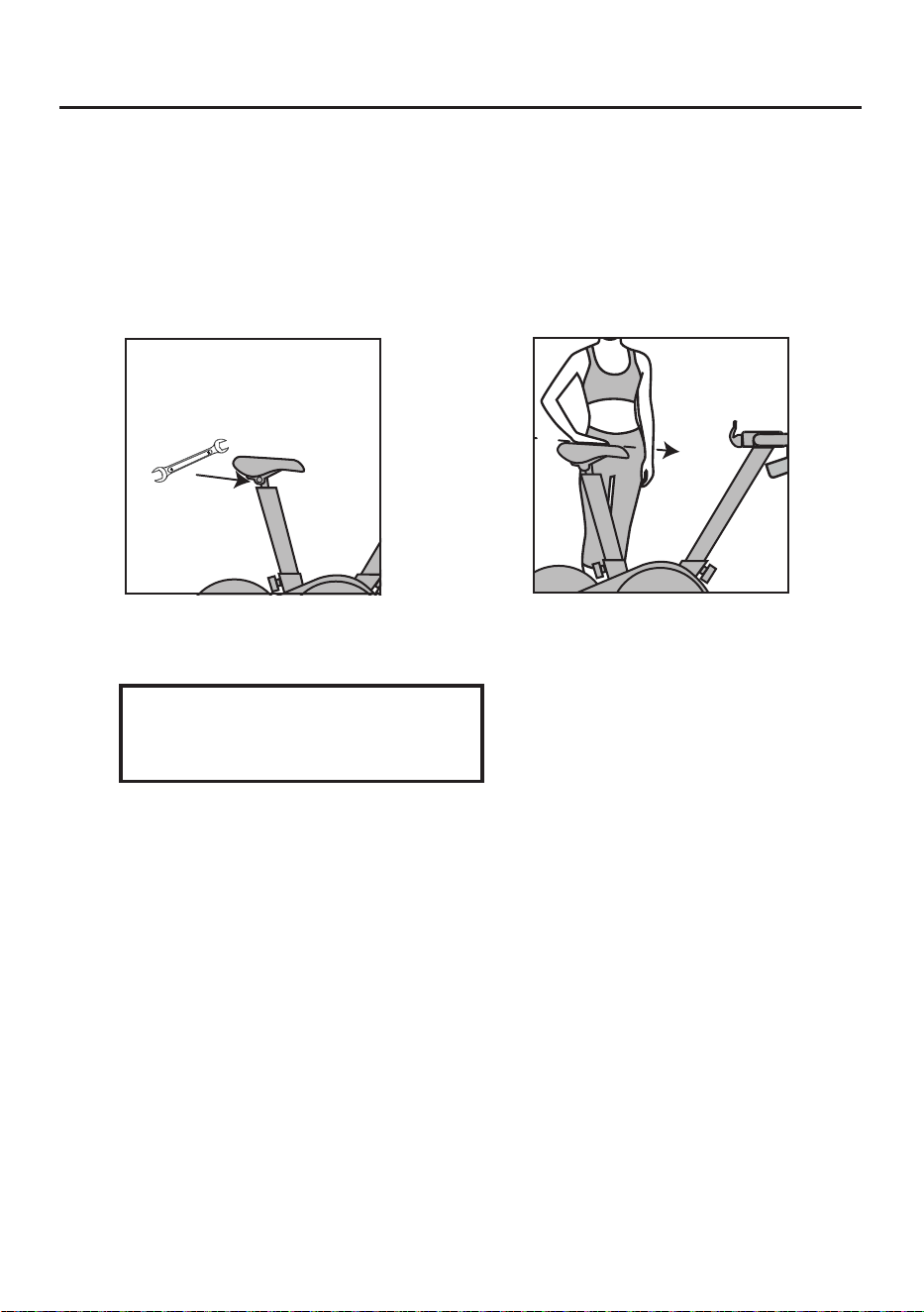
How to Determine Correct Riding Posture
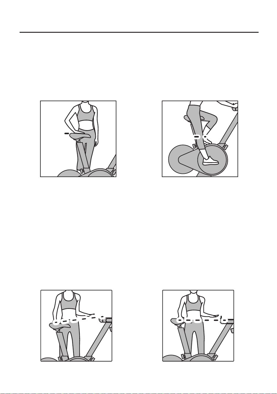
1. Setup of correct saddle position
Saddle height
Put the feet together, stand on one side of the saddle and adjust the saddle to the
hip height (Fig. 1), then sit on the saddle, step on the pedals forcibly until they are
stopped at 6 o’clock and the leg can be fully stretched (Fig. 2).
Hip joint
Leg straight
(Fig. 1) (Fig. 2)
2. Se
tup of appropriate handlebar height
(Fig. 1) (Fig. 2)
Each user can set up the appropriate handlebar height based on his or her body
height and riding experience.
Recommendation: The handlebar should be slightly higher than the saddle for
new users (Fig. 1) and flush with or slightly lower than the saddle for experienced
users (Fig. 2).
Users subject to lumbar muscle strain and lumbar spondylosis may ride the bike
with the consent of doctors. It is recommended to adjust the handlebar into a
higher position.
22
How to Determine Correct Riding Posture
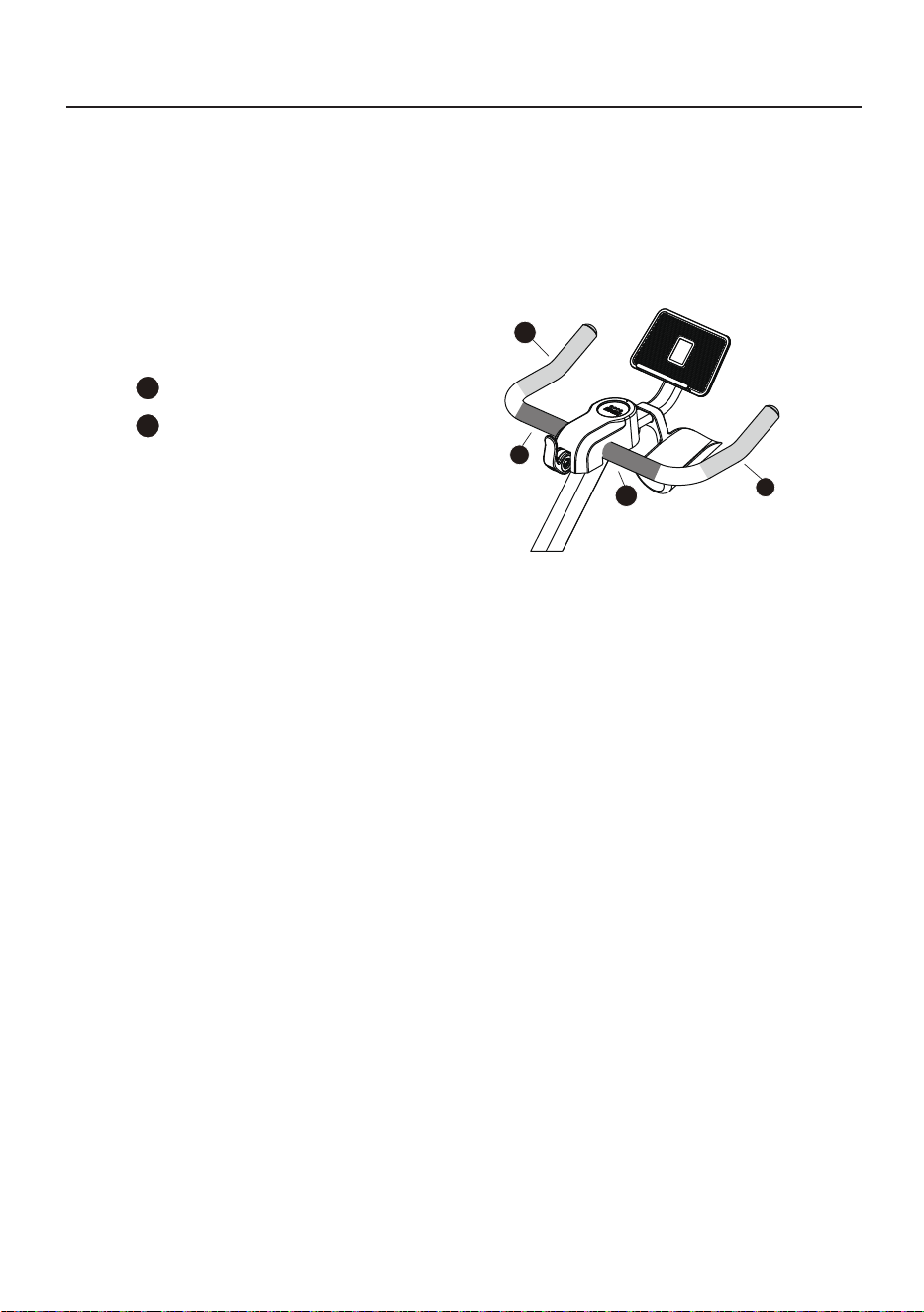
3. Handle position layout of bike
During riding, coaches will show the corresponding
hand positions, i.e. the corresponding parts of the
handlebar, as shown below.
Hand position 1
1
Hand position 2
2
1
2
2
1
23
Seat Cushion Angle Adjustment
1. Seat cushion angle adjustment
(Fig. 1) (Fig. 2)
Recommendation: The seat cushion
may be lowered slightly in case of any
hip discomfort during riding.
Slightly loosen two nuts (Fig. 1) on the left and right at the bottom of the seat
cushion via the open-ended wrench (C), and press the front part of the seat
cushion to a comfortable angle(it is recommended to adjust the seat cushion
until its front part is one notch lower), Then tighten the two nuts at the bottom.
Open-ended wrench(C)
髋关节
24
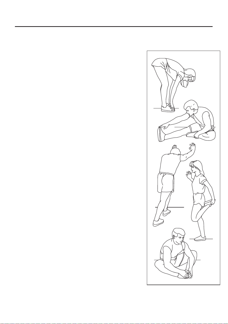
Warm up
Before exercising, it is best to do stretching exercises.
Warm muscles stretch more easily, so warm up for 5
to 10 minutes first. Then stop and stretch as follows -
5 times for 10 seconds or more on each leg, then do it
again at the end of the exercise.
1.Stretching by touching toes
Stand with your knees slightly bent and your hips moving
slowly forward. Touch yourtoes as far as possible, while
relaxing your back and shoulders. Keep this posture for 15s
and thenrelax. Repeat the exercise three times.
Stretched parts: Ligaments,internal parts of knees, andback.
(See Figure 1)
2.Ligament stretching exercise
Sit with one leg stretched forward.Put the other sole close
to your body andon the inner side of the thigh of the stretched
leg. Touch your toes as far as possible. Keep thisposture for 15s
and then relax. Exercise both legs three times, respectively.
Stretched parts:Ligaments, back and groin.(See Figure 2)
3.Calf/heel stretching exercise
Hold your hands against the wall, arms straight, body down, one
foot in front, one foot behind, hold for 15 seconds . (See Figure 3)
4.Quadriceps femoris stretching exercise
Stand with one hand against the wall for balance and the other
hand reaching back to grab your foot. Pull your heel as close to
your buttocks as possible. Keep this posture for 15 seconds and
then relax. Repeat the exercise three times for each leg. Stretched
parts: Quadriceps and hip muscles. (See Figure 4)
5.Inner thigh stretching exercise
Sit with the soles of your feet together and your knees turned out.
Make your feet asclose as possible to the groin. Keep this posture
for 15s and then relax. Repeat the exercise threetimes. Stretched
parts: Ouadriceps and hip muscles. (See Figure 5)
Note: This product is a full-body training equipment,
please follow the above steps to perform warm-up exercises.
1
2
3
4
5
25

FCC Statement
Any Changes or modifications not expressly approved by the party responsible for
compliance could void the user’s authority to operate the equipment.
This device complies with part 15 of the FCC Rules. Operation is subject to the following
two conditions:
(1)This device may not cause harmful interference, and
(2)This device must accept any interference received, including interference that may
cause undesired operation.
FCC Radiation Exposure Statement:
This equipment complies with FCC radiation exposure limits set forth for an uncontrolled
environment. This transmitter must not be co-lo-cated or operating in conjunction with
any other antenna or transmit-ter.
Note : This equipment has been tested and found to comply with the limits for a Class B
digital device, pursuant to part 15 of the FCC Rules. These limits are designed to
provide reasonable protection against harmful interference in a residential installation.
This equipment generates,uses and can radiate radio frequency energy and, if not
installed and used in accordance with the instructions, may cause harmful interference
to radio communications.However, there is no guarantee that interference will not occur
in a particular installation. If this equipment does cause harmful interference to radio or
television reception, which can be determined by turning the equipment off and on, the
user is encouraged to try to correct the interference by one or more of the following
measures:
—Reorient or relocate the receiving antenna.
—Increase the separation between the equipment and receiver.
—Connect the equipment into an outlet on a circuit different from that to which the
receiver is connected.
—Consult the dealer or an experienced radio/TV technician for help.