
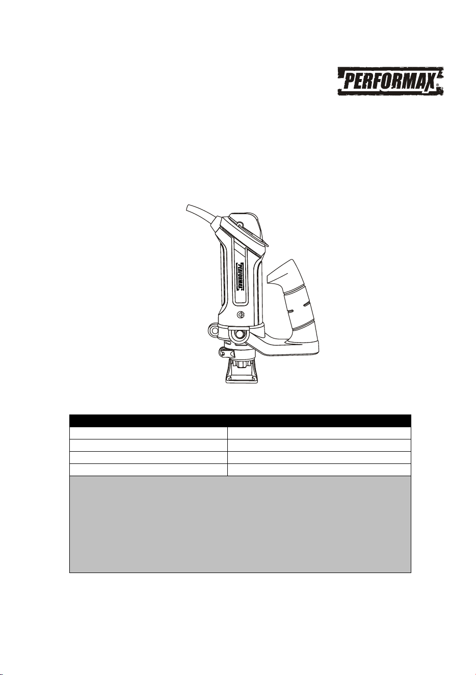
5.8 AMP. CUT-OUT SAW
241-0968
Owner’s Manual
PRODUCT SPECIFICATIONS
Rating:
120 V, 60 Hz AC
Amperes:
5.8 Amp.
Speed:
10,000 – 30,000 RPM (no load)
Weight:
3 lb 3 oz (1.45 kg)
Need Assistance?
Call us on our toll free customer support line:
1-866-349-8665
· Technical questions
· Replacement parts
· Parts missing from package

2
Product specifications ………….…………………………………………………….
1
Table of contents ……………………………………………………………………...
2
General safety warnings ……………………………………………………………..
3–4
Eye, ear & lung protection ……………………………………………………………
3–4
Electrical safety ……………………………………………………………………….
4
Power tool safety ……………………………………………………………………...
5–6
General safety rules …………………………………………………………………..
5
Work area safety ………………………………………………………………….…………..
5
Electrical safety ……………………………………………………………………….
5
Personal safety ………………………………………………………………………..
5–6
Power tool use and care.……………………………………………………………..
6
Service …………………………………………………………………………………
6
Specific safety rules …………………………………………………………………..
7
Extension cord safety ………………………………………………………….……..
8
Symbols ………………………………………………………………………………..
9
Know your cut-out saw ……………………….......................................................
10
Available accessories ………………………………………………………………...
10
Contents ……………………………………………………………………………….
11
Assembly and operating ……………………………………………………………..
12–25
Installing the assist handle …………………………………………………………..
12
Installing the freehand cutting guide ………………………………………………..
13
Installing cutting bits ………………………………………………………………….
13–14
Changing the collet …………………………………………………………………...
15
ON/OFF switch ………………………………………………………………………..
16
Speed control switch ………………………………………………………………….
16
Adjusting the freehand cutting guide ………………………………………………..
16–17
Cutting bit applications ……………………………………………………………….
18
Practice cuts using freehand cutting guide ………………………………………...
19–20
Cutting tips …………………………………………………………………………….
20–21
Cutting outlet openings in drywall …………………………………………………...
21–23
Installing the circle cutting guide …………………………………………………….
23–24
Circle cutting guide operation ………………………………………………………..
24–25
Maintenance …………………………………………………………………………..
26
Exploded view ………………………………………………………………………...
27
Parts list …………………………………………………………………………….....
28–29
Warranty ……………………………………………………………………….………
30
TABLE OF CONTENTS
3
EYE, EAR & LUNG PROTECTION
This instruction manual includes the following:
· General Safety Rules
· Specific Safety Rules and Symbols
· Functional Description
· Assembly
· Operation
· Maintenance
· Accessories
!
ALWAYS WEAR EYE PROTECTION THAT CONFORMS WITH CSA
REQUIREMENTS or ANSI SAFETY STANDARD Z87.1
FLYING DEBRIS can cause permanent eye damage. Prescription
eyeglasses ARE NOT a replacement for proper eye protection.
WARNING: Non-compliant eyewear can cause serious injury if
broken during the operation of a power tool.
SAVE THESE INSTRUCTIONS FOR REFERENCE
WARNING: Use hearing protection, particularly during extended
periods of operation of the tool, or if the operation is noisy.
!
GENERAL SAFETY WARNINGS
WARNING: Before using this tool or any of its accessories, read this
manual and follow all Safety Rules and Operating Instructions. The important
precautions, safeguards and instructions appearing in this manual are not
meant to cover all possible situations. It must be understood that common
sense and caution are factors which cannot be built into the product.
!
4
ELECTRICAL SAFETY
WARNING: To avoid electrical hazards, fire hazards or damage to the
tool, use proper circuit protection.
This tool is wired at the factory for 120V AC operation. It must be connected
to a 120V AC, 15 AMP circuit that is protected by a time-delayed fuse or
circuit breaker. To avoid shock or fire, replace power cord immediately if it
is worn, cut or damaged in any way.
GENERAL SAFETY WARNINGS
WEAR A DUST MASK THAT IS DESIGNED TO BE USED WHEN
OPERATING A POWER TOOL IN A DUSTY ENVIRONMENT.
WARNING: Dust that is created by power sanding, sawing, grinding,
drilling, and other construction activities may contain chemicals that are
known to cause cancer, birth defects, or other genetic abnormalities. These
chemicals include:
Lead from lead-based paints
Crystalline silica from bricks, cement,
and other masonry products
Arsenic and chromium from chemically treated lumber
The level of risk from exposure to these chemicals varies, according to how
often this type of work is performed. In order to reduce exposure to these
chemicals, work in a well-ventilated area, and use approved safety
equipment, such as a dust mask that is specifically designed to filter out
microscopic particles.
!
SAVE THESE INSTRUCTIONS FOR REFERENCE

5
WARNING: Read all safety warnings
and instructions. Failure to follow the
warnings and instructions may result in
electric shock, fire and/or serious injury.
Save all warnings and instructions for
future reference.
Work area safety
Keep work area clean and well lit.
Cluttered or dark areas invite accidents.
Do not operate power tools in explosive
atmospheres, such as in the presence
of flammable liquids, gases or dust.
Po
wer tools create sparks which may
ignite the dust or fumes.
Keep children and bystanders away
while operating a power tool.
Distractions can cause you to lose control.
Electrical safety
Power tool plugs must match the outlet.
Never modify the plug in any way. Do
not use any adapter plugs with earthed
(grounded) power tools. Unmodified
plugs and matching outlets will reduce risk
of electric shock.
Avoid body contact with earthed or
ground
ed surfaces such as pipes,
radiators, ranges and refrigerators.
There is an increased risk of electric shock
if your body is earthed or grounded.
Do not expose power tools to rain or
wet conditions. Water entering a power
tool will increase the risk of electric shock.
Do not abuse the cord. Never use the
cord for carrying, pulling or unplugging
the power tool. Keep cord away from
heat, oil, sharp edges or moving parts.
Damaged o
r entangled cords increase the
risk of electric shock.
When operating a power tool outdoors,
use an extension cord suitable for
outdoor use. Use of a cord suitable for
outdoor use reduces the risk of electric
shock.
If operating a power tool in a damp
location is unavoidable, use a residual
current device (RCD) protected supply.
Use of a ground fault circuit interrupter
(GFCI) reduces the risk of electric shock.
Personal safety
Stay al
ert, watch what you are doing
and use common sense when operating
a power tool. Do not use a power tool
while you are tired or under the
influence of drugs, alcohol or
medication. A moment of inattention while
operating power tools may result in serious
personal injury.
Use personal protective equipment.
Always wear eye protection. Protective
equipment such as dust mask, non-skid
safety shoes, hard hat, or hearing
protection used fo
r appropriate conditions
will reduce personal injuries.
Prevent unintentional starting. Ensure
the switch is in the off-position before
connecting to power source and/or
battery pack, picking up or carrying the
tool. Carrying power tools with your finger
on the switch or energizing power tools
that have the switch on invites accidents.
Remove any adjusting key or wrench
before turning the power tool on. A
wrench or a key left attache
d to a rotating
part of the power tool may result in
personal injury.
POWER TOOL SAFETY
!
SAVE THESE INSTRUCTIONS FOR REFERENCE

6
PERSONAL SAFETY – cont’d
Do not overreach. Keep proper footing
and balance at all times. This enables
better control of the power tool in
unexpected situations.
Dress properly. Do not wear loose
clothing or jewelry. Keep your hair,
clothing and gloves away from moving
parts. Loose clothes, jewelry or long hair
can be caught in moving parts.
If devices are provided for the
connection of dust extraction and
collection facilities, ens
ure these are
connected and properly used. Use of
dust collection can reduce dust-related
hazards.
Power tool use and care
Do not force the power tool. Use the
correct power tool for your application.
The correct power tool will do the job
better and safer at the rate for which it was
designed.
Do not use the power tool if the switch
does not turn it on and off. Any power
tool that cannot be controlled with the
switch is dangerous and mu
st be repaired.
Disconnect the plug from the power
source and/or the battery pack from the
power tool before making any
adjustments, changing accessories, or
storing power tools. Such preventive
safety measures reduce the risk of starting
the power tool accidentally.
Store idle power tools out of the reach
of children and do not allow persons
unfamiliar with the power tool or these
instructions to operate the power tool.
Power to
ols are dangerous in the hands of
untrained users.
Maintain power tools. Check for
misalignment or binding of moving
parts, breakage of parts and any other
condition that may affect the power
tool’s operation. If damaged, have the
power tool repaired before use. Many
accidents are caused by poorly maintained
power tools.
Keep cutting tools sharp and clean.
Properly maintained cutting tools with
sharp cutting edges are less likely to bind
and are easier to control.
Use the power tool, accessories and
tool bits etc. in accordance with these
instructions, taking into account the
working conditions and the work to be
performed. Use of the power tool for
operations different from those intended
could result in a hazardous situation.
Hold power tools by insulated gripping
surfaces when performing an operation
where the cutting tool may contact
hidden wiring or its own cord. Contact
with a "live" wire
will make exposed metal
parts of the tool "live" and shock the
operator.
Use clamps or another practical way to
secure and support the workpiece to a
stable platform. Holding the work by hand
or against your body leaves it unstable and
may lead to loss of control.
Service
Have your power tool serviced by a
qualified repair person using only
identical replacement parts. This will
ensure that the safety of the power tool is
mainta
ined.
POWER TOOL SAFETY
SAVE THESE INSTRUCTIONS FOR REFERENCE

7
WARNING: Know your cut-out
saw. Read the Owner’s Manual
carefully. Learn the tool’s applications
and limitations, as well as the specific
potential hazards related to this tool.
Following this rule will reduce the risk of
electric shock, fire or serious injury.
Always wear eye protection.
Any power tool can throw
foreign objects into your eyes
and cause permanent eye
damage. ALWAYS wear safety goggles
(not glasses) that comply with ANSI safety
standard Z87.1. Everyday glasses hav
e
only impact resistant lenses. They ARE
NOT safety glasses.
WARNING: Wearing glasses or
goggles that do not comply with ANSI
Z87.1 could cause serious injury if they
break.
Always wear hearing protection and a dust
mask when sanding. Use only in a well-
ventilated area. Using personal safety
devices and working in a safe environment
reduces the risk of injury.
WARNING: Always unplug the
tool from the power source befor
e
changing the bit or an accessory and
when cleaning the tool.
Do not wear gloves, neckties or loose
clothing.
Hold tool by the insulated gripping
surfaces when performing an operation
where the cutting tool may contact hidden
wiring or its own cord. Contact with a “live”
wire will make exposed metal parts of the
tool “live” and shock the operator.
Always make sure the work surface is free
from nails and other forei
gn objects.
Cutting into a nail can cause the bit and
the tool to jump and damage the bit.
Always use a safe method to secure the
workpiece, and use both hands to guide
the tool. Never place your hands near or
below the cutting surface.
Never lay the workpiece on hard surfaces
like concrete, stone, etc. The protruding
cutting bit may cause the tool to jump.
After changing the bits, accessories and
making adjustments, make sure the co
llet
nut and any other adjustment devices are
securely tightened. Loose adjustment
devices will be violently thrown.
Never use dull or damaged bits. Sharp bits
must be handled with care. Damaged bits
can snap during use. Dull bits require more
force to push the tool, possibly causing the
bit to break.
Never touch the bit during or immediately
after use. After use the bit is too hot to be
touched by bare hands.
SPECIFIC SAFETY RULES
!
!
!
SAVE THESE INSTRUCTIONS FOR REFERENCE

8
WARNING: Keep the extension
cord clear of the working area. Position
the cord so it will not get caught on the
workpiece, tools or any other
obstructions
while you are working with the power tool.
Make sure any extension cord used with
this tool is in good condition. When using
an extension cord, be sure to use one of
heavy enough gauge to carry the current
the tool will draw. An undersized cord will
cause a drop in line vo
ltage resulting in
loss of power and overheating.
The table at right shows the correct size to
use according to cord length and
nameplate ampere rating. If in doubt, use
the next heavier gauge. The smaller the
gauge number the heavier the cord.
Be sure your extension cord is properly
wired and in good condition. Always
replace a damaged extension cord or have
it repaired by a qualified electrician before
using it. Protect your extensi
on cord from
sharp objects, excessive heat and damp or
wet areas.
Use a separate electrical circuit for your
power tools. This circuit must not be less
than 14 gauge wire and should be
protected with either a 15 AMP time
delayed fuse or circuit breaker. Before
connecting the power tool to the power
source, make sure the switch is in the OFF
position and the power source is the same
as indicated on the nameplate. Running at
lower voltage will
damage the motor.
!
MINIMUM GAUGE (AWG)
EXTENSION CORDS (120V use only)
Amperage
rating
Total length
More
than
Not
more
than
25'
(7.5 m)
50'
(15 m)
100'
(30 m)
150'
(45 m)
0
6
18
16
16
14
6
10
18
16
14
12
10
12
16
16
14
12
12
16
14
12
Not Applicable
EXTENSION CORD SAFETY
9
V
Volts
A
Amperes
Hz
Hertz
W
Watts
kW
Kilowatts
Microfarads
L
Liters
kg
Kilograms
H
Hours
N/cm
2
Newtons per square
centimeter
Pa
Pascals
OPM
Oscillations per minute
Min
Minutes
S
Seconds
or a.c.
Alternating current
Three-phase alternating
current
Three-phase alternating
current with neutral
Direct current
No load speed
Alternating or direct
current
Class II construction
Splash-proof
construction
Watertight construction
Protective grounding at
grounding terminal,
Class I tools
Revolutions or
reciprocations per
minute
Diameter
Off position
Arrow
Warning symbol
Wear your safety
glasses
SYMBOLS
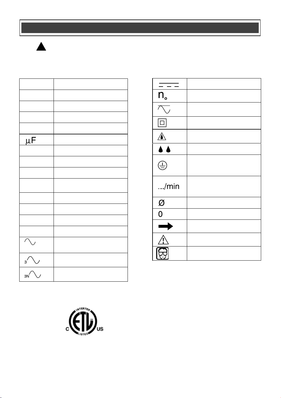
WARNING: Some of the following symbols may appear on the cut-out
saw. Study these symbols and learn their meaning. Proper interpretation of
these symbols will allow for more efficient and safer operation of this tool.
!
3042597
JD3362U
LISTED
This symbol designates that this tool is
l
isted with U.S. requirements by ETL
T
esting Laboratories, Inc.
C
onforms to UL Std. 745-1, 745-2-17.
10
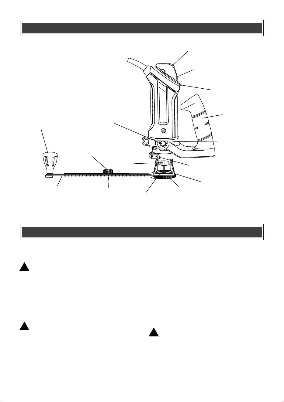
Speed control
wheel
ON/OFF switch
Freehand
guide foot
Mounting disc
Freehand cutting
guide collar
Pivot point
Locking knob
Circle cutting
guide
Locking lever
Spindle locking
button
Pivot point
Mounting
insert
Hanging loop
Circle cutting
knob
Side assist
handle
Collet nut
AVAILABLE ACCESSORIES
WARNING: Use only accessories
that are recommended for this cut-out
saw. Follow the instructions that
accompany the accessories. The use of
improper accessories may result in
injury to the operator or damage to the
cut-out saw.
WARNING: Router bits are NOT
recommended for use with this tool.
Before using any accessory, carefully
read
the instructions or the owner’s manual for
the accessory.
· 1/8" Cutting bits
· 1/8" Hobby rotary tool accessories
· Cutters
· Polishers
· Sanders
· Grinders
WARNING: If any part is missing or
damaged, do not plug the cut-out saw into
the power source until the missing or
damaged part is replaced.
KNOW YOUR CUT-OUT SAW
ACCESSORIES
!
!
!
11
CONTENTS
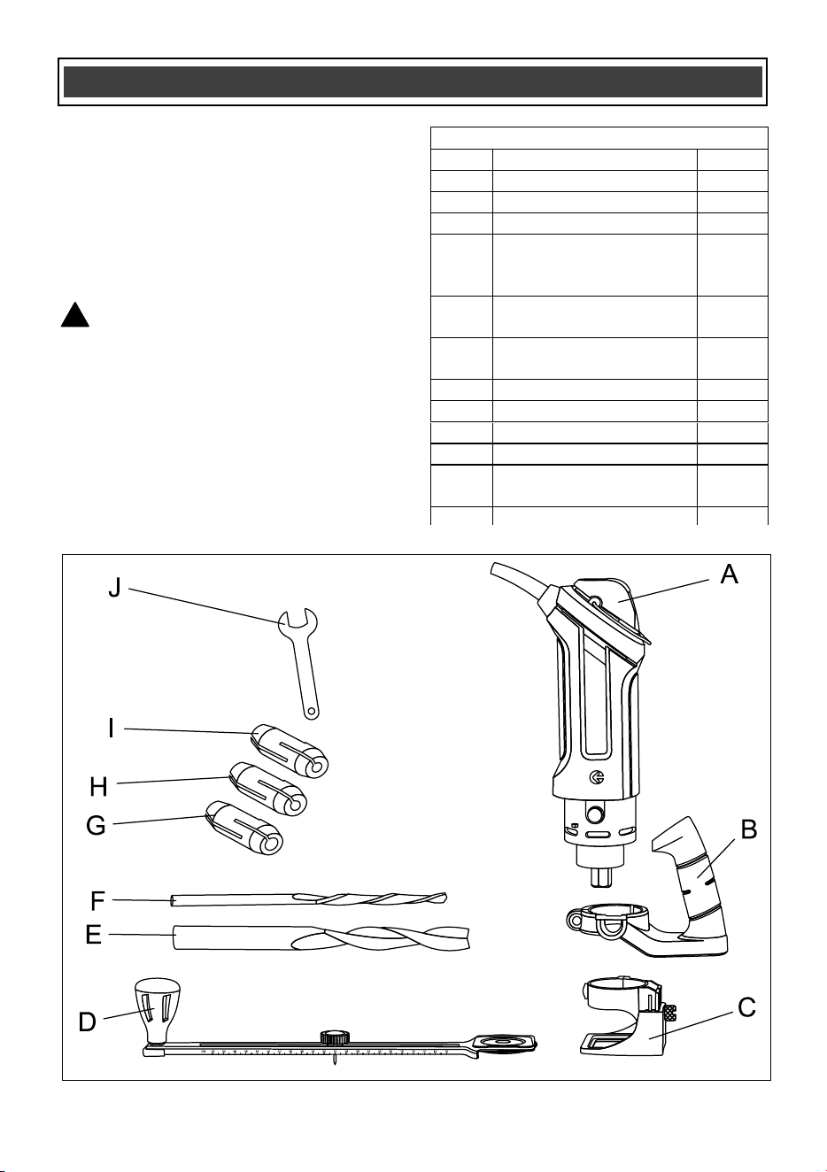
Carefully unpack the cut-out saw.
Compare the contents against the “CUT-
OUT SAW COMPONENTS” chart at right.
NOTE: See illustration of the cut-out saw
below.
WARNING: To avoid fire or toxic
reaction, never use gasoline, naphtha,
acetone, lacquer thinner or similar
highly volatile solvents to clean the
tool.
!
CONTENTS
CUT-OUT SAW COMPONENTS
KEY
DESCRIPTION
QTY
A
Cut-out saw
1
B
Side assist handle
1
C
Freehand cutting guide
1
D
Circle cutting guide
with installation
adapter
1
E
1/4" general purpose
cutting bit
1
F
1/8" general purpose
cutting bit
2
G
1/4" collet
1
H
5/32" collet
1
I
1/8" collet
1
J
Collet wrench
1
Tote case
(Not illustrated)
1
Owner’s Manual
1
12
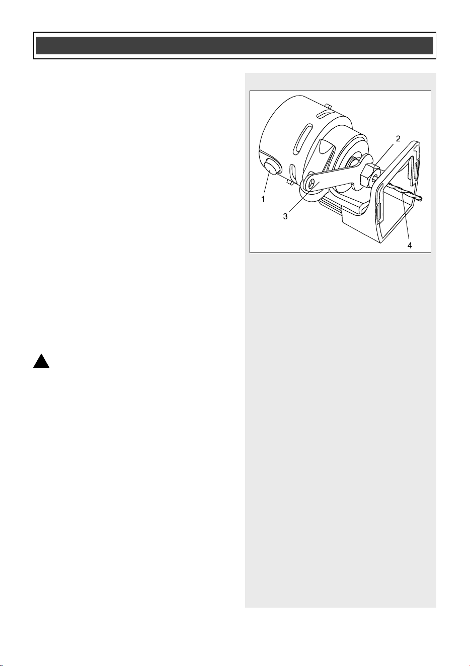
Fig. 1
WARNING: Remove the plug from
the power source before assembly,
changing accessories or cutters and
making adjustments. This will prevent
accidental starting of the tool which
could result in serious injury.
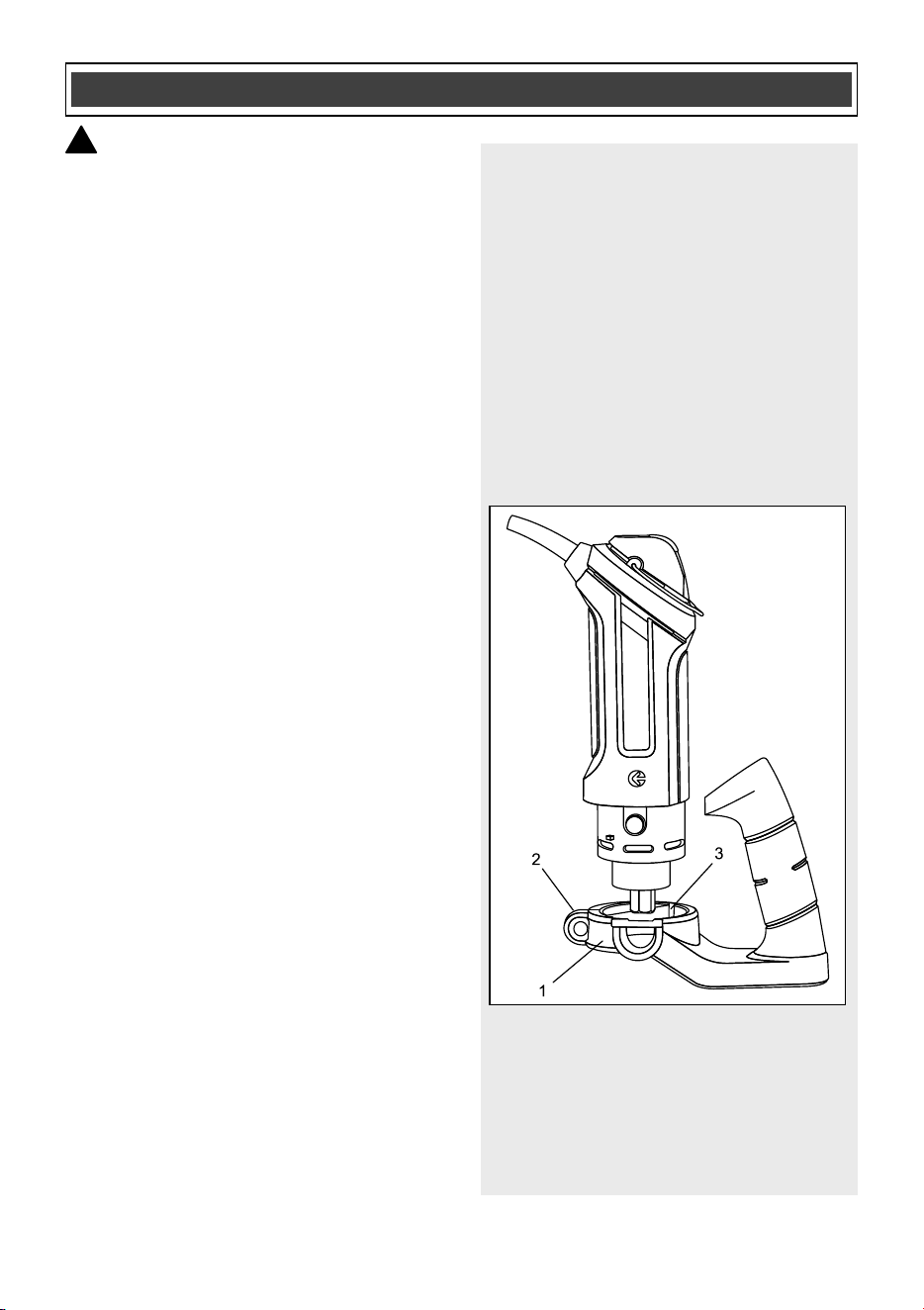
INSTALLING THE ASSIST HANDLE
The removable assist handle is designed
for use when precision control over the tool
movement is desired. Use the assist
handle when operating the tool with either
the freehand cutting guide or
the circle
cutting guide.
1. Open the mounting collar (1) by
pulling the quick release lever (2)
outward (Fig. 1).
2. Slide the mounting collar onto the
bottom of motor housing (2). Make
sure the key (3) on the motor housing
is aligned with the matching keyway in
the mounting collar.
3. When the key and keyway are
aligned, slide the mounting collar fully
onto the motor housing and then
rotate the collar clockwise
approxima
tely 10° to lock the key and
keyway.
NOTE: The mounting bracket must be
pushed onto the motor housing as far as it
will go.
4. Press the quick release lever inward
toward the mounting collar to finish
locking the mounting collar onto the
motor housing.
ASSEMBLY AND OPERATING
!
Fig. 1
13
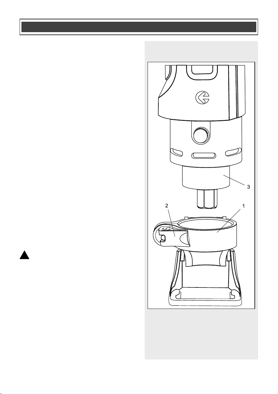
INSTALLING THE FREEHAND CUTTING
GUIDE
The freehand cutting guide is designed for
basic freehand cutting with the cutting bit.
It is ideally suited for cutting electrical
outlet holes in drywall.
1. Open the freehand cutting guide
mounting collar (1) by pulling the quick
release lever (2) outward (Fig. 2).
2. Slide the mounting collar onto the
bottom of the motor housing (3).
NOTES:
a) The mounting collar must be pushed
onto t
he motor housing as far as it will
go.
b) Rotate the mounting collar to position
it to provide the best visibility to the
bit.
3. Lock the freehand cutting guide onto
the motor housing by pushing the
quick release lever inward toward the
mounting collar until it snaps into the
locked position.
INSTALLING CUTTING BITS
WARNING: Cutting bit surfaces
are extremely sharp. Handle with
caution.
To loosen and tighten the collet use the
collet wrench supplied with the tool.
ASSEMBLY AND OPERATING
!
Fig. 2
14
INSTALLING CUTTING BITS – cont’d
1. Depress the shaft locking button (1)
and rotate the collet lock nut (2) with
the other hand until the locking button
drops into place, preventing the shaft
from turning (Fig. 3).
2. While continuing to hold the shaft
locking button IN, use the collet
wrench (3) to turn the collet nut
counterclockwise. Loosen the collet
nut two or three turns.
3. Remove the bit if one is already
installed in the
tool.
4. Insert the new cutting bit (4) into the
collet.
NOTE: If the shank of the bit being
installed is a different size than the bit
being removed, install the correct collet as
outlined in Fig. 4.
WARNING: Insert the bit all the
way into the collet and then pull it back
between 1/16" and 1/8". This creates an
air space between the motor shaft and
the bit to help protect the bit from
overheating.
Before
tightening the collet on the bit,
make sure the flutes (spiral portion) of
the bit are completely visible outside
the collet. Clamping the collet on the bit
flutes will result in broken bits and
possible injury.
5. When the bit is properly placed in the
collet, depress the shaft locking button
and turn the collet nut clockwise by
hand as far as possible.
6. Securely tighten the collet nut using
the collet wrench.
ASSEMBLY AND OPERATING
!
Fig. 3

15
CHANGING THE COLLET
The cutting bits for this tool are locked into
place with a collet nut (1) and collet (2)
(Fig. 4). 1/8" and 5/32" collets are used for
holding 1/8" and 5/32" cutting bits and
hobby tool accessory bits. The 1/4" collet
is supplied for holding 1/4" drywall bits.
To change from one collet size to the
other:
1. Remove bit from the tool.
2. Turn the collet nut counterclockwise
until it can be removed from
the motor
shaft (3) (Fig. 4).
3. Pull the collet out of the motor shaft
and insert the new collet.
NOTE: Each collet is the same on both
ends, so either end can be inserted into
the motor shaft.
Reinstall the collet nut and slightly tighten
it by hand.
NOTE: Tightening the collet nut without a
bit in the collet will cause the collet hole to
become smaller and make installing bits
difficult. When storing the tool with no bit
installed, leave the collet nut loose.
ASSEMBLY AND OPERATING
Fig. 4
16
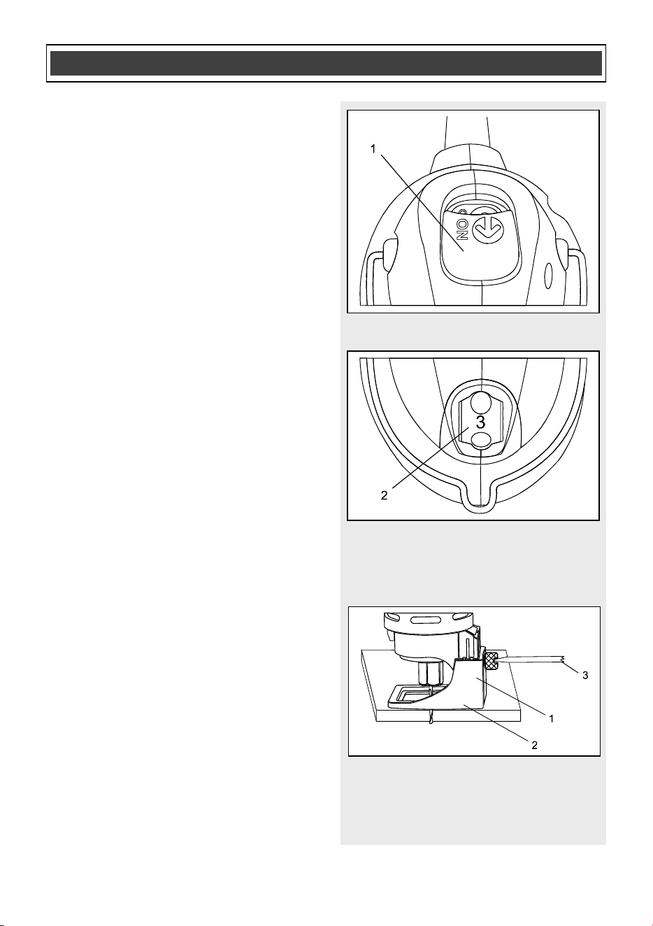
ON/OFF SWITCH
This cut-out saw is equipped with a
convenient ON/OFF switch (1) located on
the top of the tool handle (Fig. 5). To turn
the switch ON, slide the switch outward.
To turn the switch OFF, slide the switch
inward.
SPEED CONTROL SWITCH
The cut-out saw is equipped with a
variable speed control located below the
ON/OFF switch. To run the tool at its
slowest speed, rotate the speed control
wheel (2) to number “1” (F
ig. 6). To
increase the tool speed, rotate the speed
control wheel in the opposite direction.
Maximum speed will be achieved at “6”.
ADJUSTING THE FREEHAND CUTTING
GUIDE
1. Adjust the freehand cutting guide
depth by loosening the depth gauge
locking screw (1) and moving the
cutting guide foot (2) up or down as
required (Fig. 7).
NOTE: Set the foot so the cutting bit
protrudes beyond the bottom of the cutting
guide 1/8" more than the th
ickness of the
material being cut. For example, if you are
cutting 5/8" drywall, the bit should protrude
3/4" beyond the bottom of the cutting
guide.
2. Securely tighten depth gauge locking
screw.
NOTE: Hand tightening is normally
adequate. If you use a screwdriver (3), do
not overtighten the locking screw.
ASSEMBLY AND OPERATING
Fig. 5
Fig. 6
Fig. 7
17
ADJUSTING THE FREEHAND CUTTING
GUIDE – cont’d
Before starting to cut, double check the bit
depth. Make sure the cutting guide is at a
right angle to the bit and securely
tightened. Double check the collet to make
sure the bit is securely fastened.
ASSEMBLY AND OPERATING
For safety reasons, the operator
must read the sections of this
Owner’s Manual entitled “GENERAL
SAFETY WARNINGS”, “POWER
TOOL SAFETY”, “SPECIFIC SAFETY
RULES”, “EXTENSION CORD
SAFETY” and “SYMBOLS” before
using this cut-out saw.
Verify the following every time the
cut-out saw is used:
1. The cord is not damaged.
2. The bit is securely fastened in
the collet.
3. The bit is sharp and in good
condition.
4. Safety glasses, hearing
protection and dust mask are
being worn.
Failure to adhere to these safety
rules can greatly increase the
chances of serious injury.
WARNING
!

18
CUTTING BIT APPLICATIONS
Soft wood* refers to spruce, pine and fir (SPF)
NOTE: Refer to the above chart for materials, material thickness, speed of the tool and
recommended cut feet per minute to be used with the various cutting bits. The speeds
referenced chart are intended as a guide only and must be adjusted according to
hardness, density and characteristics of the material being cut. Material thickness must
never exceed the length of the cutting flutes. Making practice cuts on a scrap workpiece
that
is the same material as the good workpiece will assist you in selecting the speeds
that will produce the smoothest cut.
Cutting Bit Type
Material and Thickness
Speed control
wheel setting
Recommended
Cut Feet per
Minute
1/4" (soft wood*,
fiberglass and laminate)
Fiberglass and laminate up
to 1/4" and soft wood* up to
1"
3–6 1 ft./min
1/4" (windows and
doors)
Drywall, gypsum board up to
5/8"
3–6
1.5 ft./min
1/8" (soft wood*,
fiberglass and laminate)
Fiberglass and laminate up
to 1/8", soft wood* up to 1"
3–6
1 ft./min.
5/32" All purpose
(not included)
All materials and thicknesses
listed in this chart plus sheet
metal up to 1/32" thick
3–6
0.5 to 1.5 ft./min.
depending upon
the material
1/8" Ceramic tile
(not included)
“Porous” ceramic wall tiles
up to 3/8"
3–6
0.5 ft./min.
ASSEMBLY AND OPERATING
19
PRACTICE CUTS USING THE
FREEHAND CUTTING GUIDE
Before attempting to work on an actual
project, take the time to make a few
practice cuts with your cut-out saw. Use
some scraps of material that are the same
material as will be used in your actual
project.
1. Draw a pattern similar to your first
project on a scrap piece of material.
2. Install the assist handle and the
freehand cutting guide as shown in
Fig. 1 & 2.
3. Install cu
tting bit in the collet as shown
in Fig. 3.
4. Adjust depth of freehand cutting guide
as shown in Fig. 7.
5. Set the speed control switch to the
appropriate speed.
6. Rest the edge of the cutting guide on
the workpiece with the bit at an angle
of about 45° (Fig. 8).
NOTE: DO NOT let the bit come into
contact with the workpiece until the power
switch is turned ON and the tool is up to
full speed.
WARNING: Before turning the
power switch ON, make sure you are
holding the tool firmly with both hands.
Starting torque will cause the tool to
twist.
7. Turn the switch ON.
ASSEMBLY AND OPERATING
!
Fig. 8
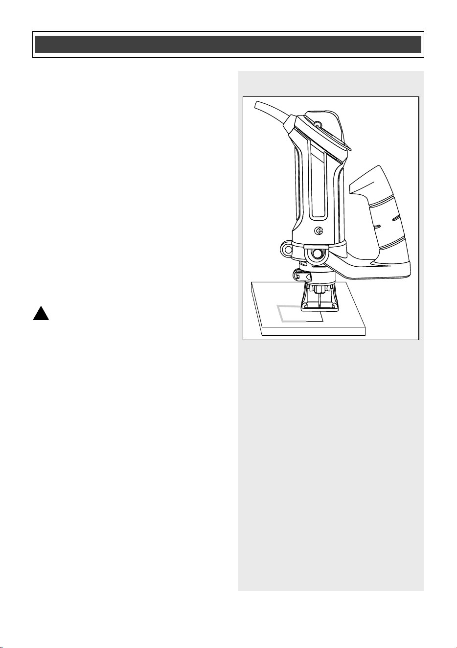
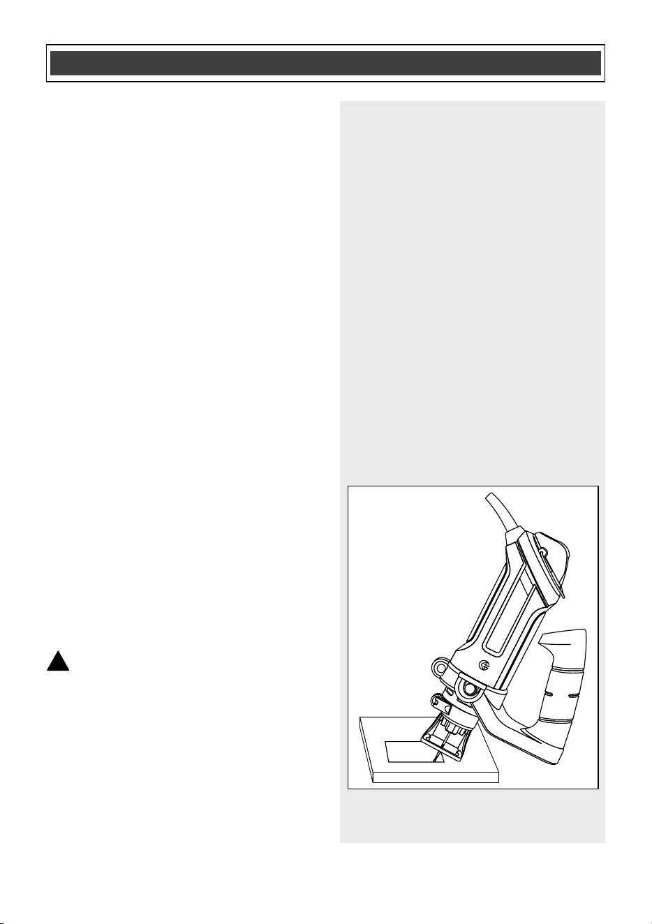
20
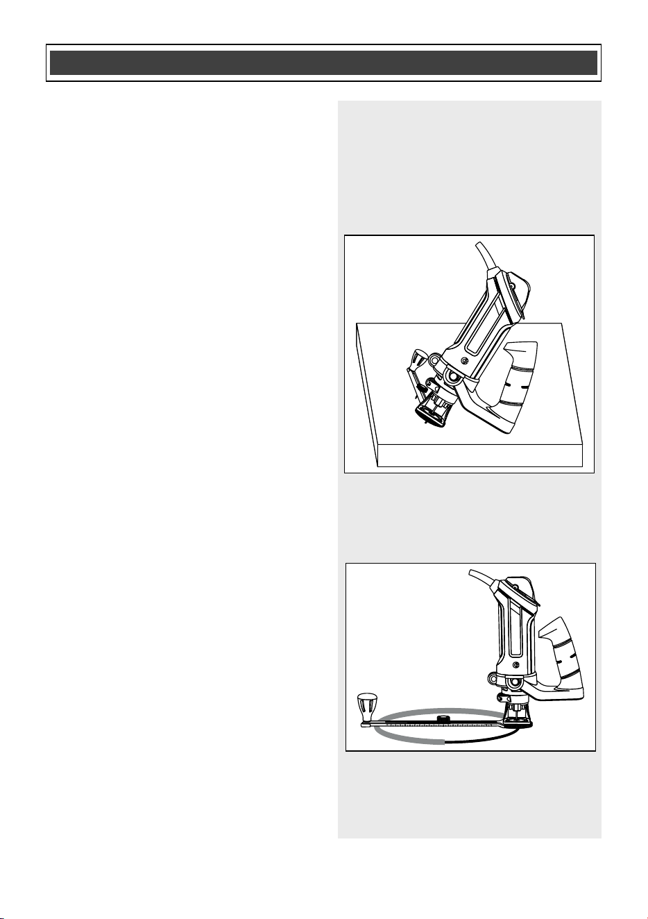
PRACTICE CUTS USING THE FREEHAND
CUTTING GUIDE – cont’d
8. When the motor is up to full speed,
slowly tip the tool to an upright
position, letting the bit cut into the
workpiece (Fig. 9). Once the tool has
reached the upright position and the
bit has cut through the workpiece,
slowly move the tool in a clockwise
direction using slow steady pressure
to make the cut.
NOTE: Except for cutting around outlet
boxes in drywall, always cut
in a
clockwise direction.
9. When the cut is complete, turn the tool
OFF, wait until it comes to a complete
stop and remove it from the
workpiece.
DANGER: Do not attempt cutting
around outlet boxes in drywall until:
1. All electricity in the vicinity of
electric wires has been
disconnected by either turning the
breaker OFF or removing the fuses.
2. You have read the instructions on
the following page entitled
“CUTTING OUTLET OPENINGS IN
DRYWALL”.
CU
TTING TIPS
The rotating cutting action of the bit will
cause a slight pull to the left when cutting.
Natural variations in the structure of wood
will cause the bit to “wander”. This
tendency will be magnified when applying
too much pressure to the bit.
ASSEMBLY AND OPERATING
!
Fig. 9

21
CUTTING TIPS – cont’d
Slower cutting gives you better control.
Excessive pressure or fast cutting will
increase the bit temperature and shorten
the life of the bit.
When cutting a hole in a vertical surface,
avoid ending the cut at the bottom of the
hole. Always start and end the cut at the
“top” so the cut out part will not drop onto
the rotating bit. Always turn the tool OFF
before removing it from the workpiece.
CUTTIN
G OUTLET OPENINGS IN
DRYWALL
DANGER: Do not attempt to use
this tool to make cut outs around any
fixture or opening which has live
electrical wires or on any wall which
may have electrical wiring behind it. If a
live wire is contacted, the bit could
conduct the electric current to the tool,
creating an electrocution hazard for the
operator. Turn OFF breakers or remove
fuses to disconnect the electric circuit
in the area of
work. Always hold the tool
by its insulated housing when working
in areas where there is a possibility of
contacting electric wires. Always wear
eye, ear and dust protection when
operating this tool.
1. Before installing drywall, push the
electrical wires to the back of the
outlet box as far as possible so they
will not be cut by the bit when cutting
the opening.
2. Before fastening the drywall sheet
over the electrical box,
mark the sheet
as close as possible to the center of
the box opening. Mark should be on
the side of the drywall facing you.
ASSEMBLY AND OPERATING
!
22
CUTTING OUTLET OPENINGS IN DRYWALL –
cont’d
3. When fastening the drywall in place,
do not place nails or screws closer
than 12" from the box. This will
prevent the drywall from becoming
deformed under pressure.
4. Install the assist handle, freehand
cutting guide and cutting bit, as
outlined in Fig. 1, 2 & 3. Adjust depth
of cut so the bit will protrude 1/8"
beyond the thickness of the drywall
(Fig. 7).
5. Hold the tool firmly with
both hands
and turn it ON. Plunge the bit through
the drywall at the mark indicating the
center of the box. See Fig. 10 for
cutting pattern.
6. Move the bit slowly to the right until
you feel and hear the bit contacting
the inside of the box.
7. Pull the bit out far enough to slip it
over the edge of the box. Once the bit
is outside the box, push it back to full
depth beside the outside edge of the
box.
8. Move the tool upward while applying
slig
ht pressure toward the center of
the box. When you feel the bit reach
the top right corner of the box, move
the tool to the left while applying slight
pressure downward toward the center
of the box.
9. Continue moving the tool around the
box in a counterclockwise direction
while maintaining slight pressure
toward the center of the box. When
the box cut out is complete, turn the
tool OFF and remove it from the cut
out.
ASSEMBLY AND OPERATING
Fig. 10
23
CUTTING OUTLET OPENINGS IN DRYWALL –
cont’d
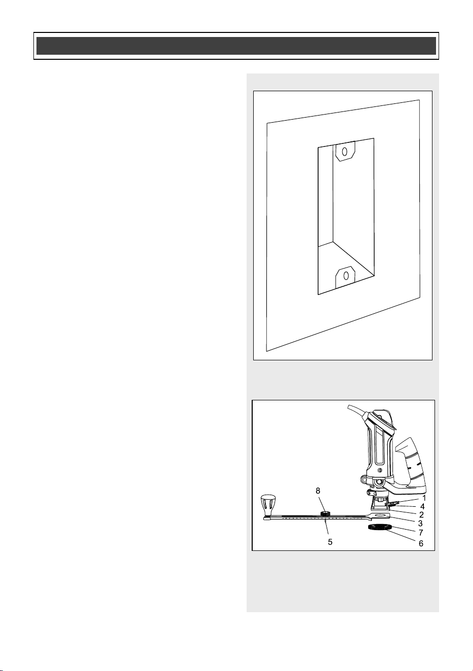
10. The completed electrical box cut out
will be accurately and neatly cut
(Fig. 11).
NOTE: Always move the cutting bit in a
counter clockwise direction around the
outlet box. The natural tendency of the
cutting bit to move to the left will make it
easier to cut close to the box.
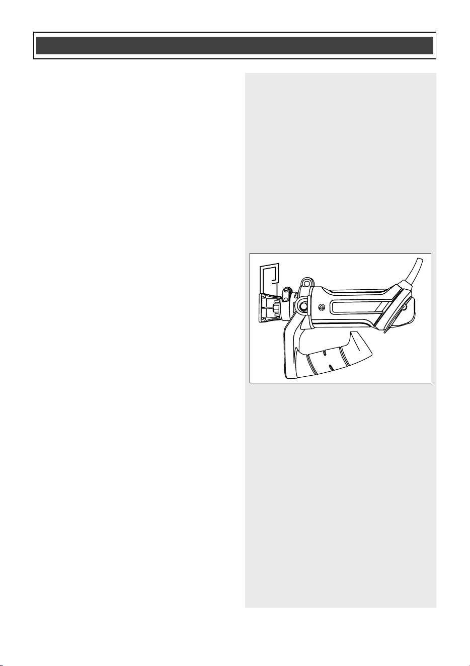
INSTALLING THE CIRCLE CUTTING
GUIDE
The circle cutting guide accessory is ideal
for precision cutting of c
ircles. This circle
cutting guide must be attached to the
freehand cutting guide.
1. Install the assist handle and install
and adjust the freehand cutting guide
on the tool as illustrated in
Fig. 1, 2, 3 & 7.
2. Insert the externally threaded circle
cutting guide mounting insert (1) into
the bottom of the freehand cutting
guide (2) (Fig. 12).
NOTE: Make sure the scallops of the
insert mate properly with the scallops
inside the freehand
cutting guide foot.
3. Place the circle cutting guide
mounting hole (3) over the externally
threaded circle cutting guide mounting
insert (4).
NOTE: Make sure pointed pivot pin (5) is
pointing away from the tool.
ASSEMBLY AND OPERATING
Fig. 11
Fig. 12
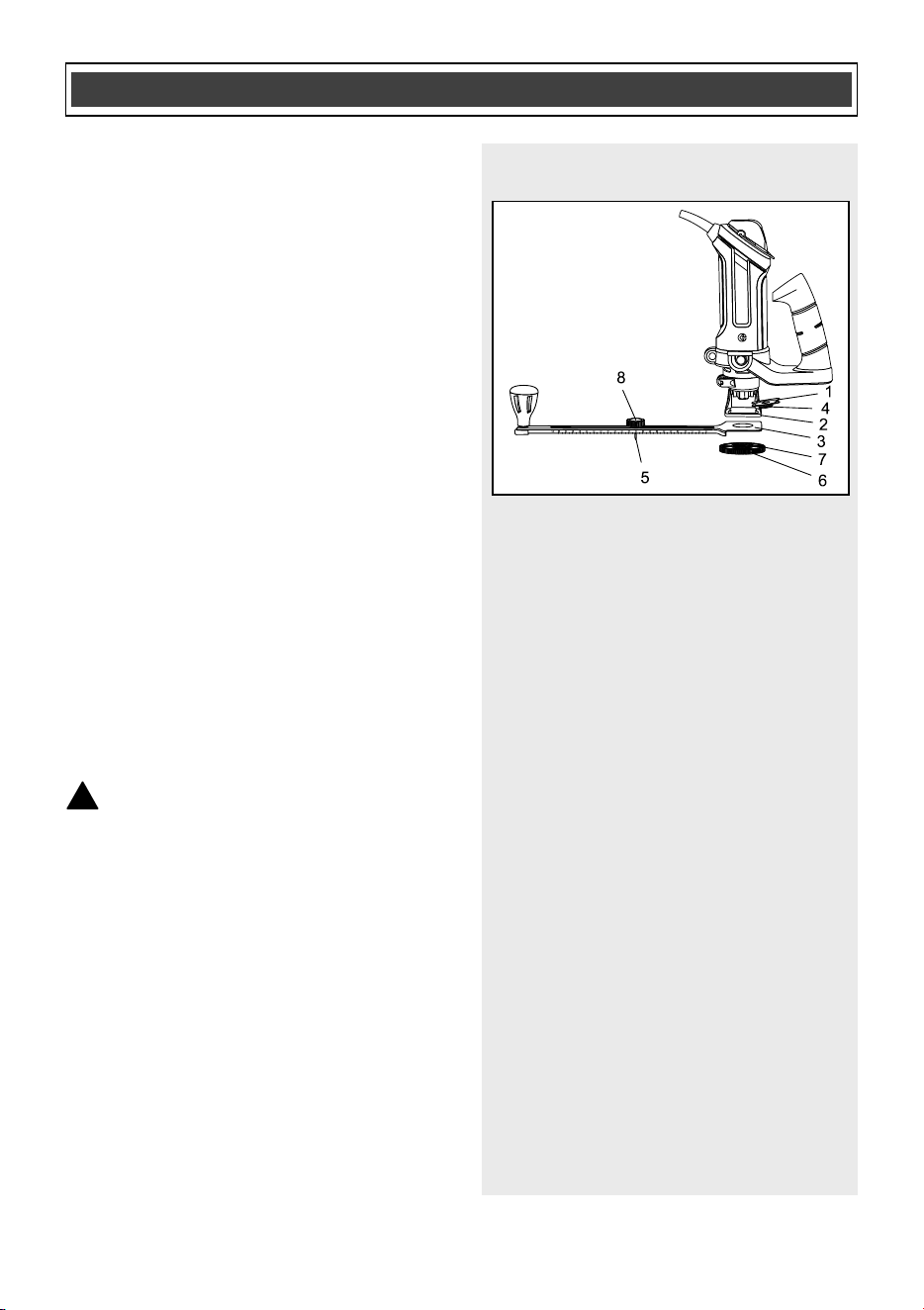
24
INSTALLING THE CIRCLE CUTTING GUIDE –
cont’d
4. Screw the internally threaded circle
cutting guide mounting disc (6) onto
the externally threaded circle cutting
guide mounting insert and hand
tighten.
NOTES:
a) Make sure the boss (7) on the cutting
guide mounting disc goes through the hole
in the circle guide.
b) Do not overtighten the circle cutting
guide mounting plastic parts. Hand tighten
only.
5. Adjust the circle cutting gui
de radius
by loosening the pivot point knob (8),
sliding it to the correct circle radius
and retightening in the desired
location.
NOTE: Check circle cutting guide radius
setting by measuring from the pivot point
to the outside of the cutting bit.
CIRCLE CUTTING GUIDE OPERATION
WARNING: Unplug the tool from
the power source before changing
accessories, changing bits and making
adjustments.
Before turning the tool ON, check
to
make sure bit and all accessory
fasteners are securely tightened.
1. Mark the center of the circle you wish
to cut on the workpiece and drill a
6 mm or 15/64" pilot hole.
2. Adjust cutting bit depth to 1/8" longer
than the thickness of the material to
be cut (Fig. 7).
ASSEMBLY AND OPERATING
!
Fig. 12
25
CIRCLE CUTTING GUIDE OPERATION –
cont’d
3. Adjust the circle cutting guide radius
by loosening the pivot point knob,
sliding it to the correct circle radius
and retightening in the desired
location.
NOTE: Check the circle cutting guide
radius setting by measuring from the pivot
point to the outside of the spiral bit.
4. Rest the edge of the freehand cutting
guide on the workpiece with the bit at
an angle of about 45° (Fig. 13
). Insert
the circle cutting guide pivot point into
the pilot hole drilled at the center of
the circle.
NOTE: DO NOT let the bit touch the
workpiece before switch is turned ON and
the tool is up to full speed.
5. Turn the switch ON.
6. When the motor is up to full speed,
slowly tip the tool and circle cutting
guide assembly to an upright position,
letting the bit cut into the workpiece
(Fig. 14). Be careful to keep t
he pivot
point located at the center of the circle
to be cut. Once the tool has reached
the upright position and the bit has cut
through the workpiece, slowly move
the tool in a clockwise direction using
slow steady pressure to make the cut.
Continue to cut the circle, keeping the
tool upright and rotating around the
circle cutting guide pivot point.
7. When cut is complete, turn the tool
OFF, wait until it comes to a complete
s
top and remove it from the
workpiece.
ASSEMBLY AND OPERATING
Fig. 13
Fig. 14

26
GENERAL
WARNING: When servicing, use
only identical replacement parts. The
use of any other part may create a
hazard or cause product damage.
DO NOT use solvents when cleaning
plastic parts. Plastics are susceptible to
damage from various types of commercial
solvents and may be damaged by their
use. Use a clean cloth to remove dirt, dust,
oil, grease etc.
WARNING: Do not allow brake
fluids, gasoline, petr
oleum-based
products, penetrating oils, etc. to come
into contact with plastic parts. They
contain chemicals that can damage,
weaken or destroy plastic.
DO NOT abuse power tools. Abusive
practices can damage the tool and the
workpiece.
WARNING: DO NOT attempt to
modify tools or create accessories. Any
such alteration or modification is
misuse and could result in a hazardous
condition leading to possible serious
injury. It will als
o void the warranty.
Remove accumulated dust and debris
regularly using a soft DRY brush.
It has been found that electric tools are
subjected to accelerated wear and
possible premature failure when they are
used on fiberglass boats and sports cars,
wallboard, spackling compounds or
plaster. The chips and grindings from
these materials are highly abrasive to
electric tool parts such as bearings,
brushes, commutators, etc. C
onsequently,
it is not recommended that this tool be
used for extended work on any fiberglass
material, wallboard, spackling compounds
or plaster. During any use on these
materials it is extremely important that the
tool is cleaned frequently by blowing it out
with an air jet.
WARNING: Always wear safety
goggles or safety glasses with side
shields during all sanding operations. It
is critical that you also wear safety
goggles or
safety glasses with side
shields and a dust mask while blowing
dust out of the cut-out saw with an air
jet. Failure to take these safety
precautions could result in permanent
eye or lung damage.
LUBRICATION
All of the bearings in this tool are
lubricated with a sufficient amount of high-
grade lubricant for the life of the unit under
normal conditions. Therefore, no further
lubrication is required.
!
MAINTENANCE
!
!
!
!
27
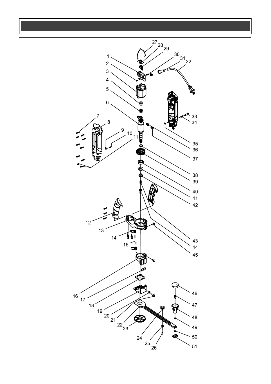
EXPLODED VIEW

28
WARNING: When servicing, use only original equipment replacement parts. The
use of any other parts may create a safety hazard or cause damage to the cut-out saw.
Any attempt to repair or replace electrical parts on this cut-out saw may create a safety
hazard unless repairs are performed by a qualified technician. For more information, call
the Toll-free Helpline, at 1-866-349-8665 Monday – Friday from 9am to 5p
m Eastern
Standard Time.
Always order by PART NUMBER, not by key number.
Key #
Part #
Part Name
Quantity
1
1130010008
V.S. PCB
1
2
4030010023
Tapping screw
1
3
1020270002
Stator
1
4
3140040006
Bearing sleeve
1
5
4010010060
Ball bearing 608-2Z
1
6
1010270002
Rotor
1
7
4030010106
Tapping screw
25
8
3011270003
Housing
1
9
2030020089
Pad
1
10
4030010020
Tapping screw
1
11
4030010099
Tapping screw
4
12
3120070026
Handle I
1
13
3150160058
Handle support
1
14
3120100002
Locking lever
3
15
2040160025
Pin
3
16
3150160019
Base support
1
17
2040150008
Locking nut
1
18
3150160009
Permanent seat
1
19
3150120011
Base plate
1
20
4040010012
Rivet
1
PARTS LIST
!

29
Key #
Part #
Part Name
Quantity
21
2040140007
Bakelite ball
1
22
2030030014
Ruler
1
23
3150100001
Round nut
1
24
1160030002
Positioning knob
1
25
4060020001
Square nut
1
26
3140080001
Protection sleeve
1
27
2050080075
Flying rings
1
28
3120110009
Switch button
1
29
1061150001
Switch
1
30
3150020005
cord clamp
1
31
3140010014
cord guard
1
32
1190030006
AC cord & plug
1
33
3120020015
Lock button
1
34
2050060023
Spring
1
35
410050002
Retaining ring
1
36
2030070016
Brush holder
2
37
1230010016
Carbon brush assembly
2
38
4100020013
Shoulder ring
1
39
3150010013
Fan
1
40
4010010058
Ball bearing 6002-2RS
1
41
3190010005
Felt seal
1
42
2040150006
Locking nut
1
43
1140060002
Collet 1/4"
1
44
2040190003
Collet nut
1
45
2030030024
Pin
3
46
3160020001
Grip cover
1
47
2040140004
Set screw
1
48
3120070003
Grip
1
49
4040010021
Rivet
1
50
4060090001
Hexagon nut
1
51
3150130013
Scale board
1
PARTS LIST

30
Rev 1.9 07/11/2022
PERFORMAX
®
5.8 AMP. CUT-OUT SAW WARRANTY
30-DAY MONEY BACK GUARANTEE:
This PERFORMAX
®
brand power tool carries our 30-Day Money Back
Guarantee. If you are not completely satisfied with your PERFORMAX
®
brand
power tool for any reason within thirty (30) days from the date of purchase, return
the tool with your original receipt to any MENARDS™ retail store, and we will
provide you a refund – no questions asked.
2-YEAR LIMITED WARRANTY:
This PERFORMAX
®
brand power tool carries a 2-Year Limited Warranty to the
original purchaser. If, during normal use, this PERFORMAX
®
power tool breaks
or fails due to a defect in material or workmanship within two (2) years from the
date of original purchase, simply bring this tool with the original sales receipt
back to your nearest MENARDS™ retail store. At its discretion, PERFORMAX
®
agrees to have the tool or any defective part(s) repair
ed or replaced with the
same or similar PERFORMAX
®
product or part free of charge, within the stated
warranty period, when returned by the original purchaser with original sales
receipt. Not withstanding the foregoing, this limited warranty does not cover any
damage that has resulted from abuse or misuse of the Merchandise. This
warranty: (1) excludes expendable parts including but not limited to blades,
brushes, belts, bits, light bulbs, and/or batteries; (2) shall be void if this tool is
used for commercial and/or rental purposes; and (3) does not cover any losses,
injuries to persons/property or costs. This warranty does give you specific legal
rights and you may have other rights, which vary from state to state. Be careful,
tools are dangerous if improperly used or maintained. Seller’s employees are
not qualified to adv
ise you on the use of this Merchandise. Any oral
representation(s) made will not be binding on seller or its employees. The rights
under this limited warranty are to the original purchaser of the Merchandise and
may not be transferred to any subsequent owner. This limited warranty is in lieu
of all warranties, expressed or implied including warranties or merchantability
and fitness for a particular purpose. Seller shall
not be liable for any special,
incidental, or consequential damages. The sole exclusive remedy against the
seller will be for the replacement of any defects as provided herein, as long as
the seller is willing or able to replace this product or is willing to refund the
purchase price as provided above. For insurance purposes, seller is not allowed
to demonstrate any of these power tools for you.
For questions /
comments, technical assistance or repair parts –
Please Call Toll Free at: 1-866-349-8665 (M-F 8am – 6pm)
SAVE YOUR RECEIPTS. THIS WARRANTY IS VOID WITHOUT THEM.
Distributed by: Menard, Inc., Eau Claire, WI 54703
