
1
2
Fig. 4
1
2
3
Fig. 5
2
Fig. 9
1
Fig. 8
1
Fig. 7
POWER TOOL SAFETY
WARNING: Read all safety warnings and
instruc�ons. Failure to follow the warnings and
instruc�ons may result in electric shock, fire
and/or serious injury.
Save all warnings and instruc�ons for future
reference.
Work area safety
Keep work area clean and well lit. Clu�ered or
dark areas invite accidents.
Do not operate power tools in explosive
atmospheres, such as in the presence of
flammable liquids, gases o
r dust. Power tools
create sparks which may ignite the dust or
fumes.
Keep children and bystanders away while
opera�ng a power tool. Distrac�ons can cause
you to lose control.
Electrical safety
Power tool plugs must match the outlet. Never
modify the plug in any way.
Do not expose power tools to rain or wet
condi�ons. Water entering a power tool will
increase the risk of electric shock.
Personal safet
y
Stay alert, watch what you are doing and use
common sense when opera�ng a power tool.
Do not use a power tool while you are �red or
under the influence of drugs, alcohol or
medica�on. A moment of ina�en�on while
opera�ng power tools may result in serious
personal injury.
Use personal protec�ve equipment. Always
wear eye protec�on.
Prevent uninten�onal star�ng. Ensure the
switch is in the off-posi�on before installing
the ba�ery p
ack, picking up or carrying the
tool. Carrying power tools with your finger on
the switch or energising power tools that have
the switch on invites accidents.
Do not overreach. Keep proper foo�ng and
balance at all �mes. This enables be�er control
of the power tool in unexpected situa�ons.
Dress properly. Do not wear loose clothing or
jewelry. Keep your hair, clothing and gloves
away from moving parts. Loose clothes, jewelry
or lon
g hair can be caught in moving parts.
Power tool use and care
Do not force the power tool. Use the correct
power tool for your applica�on. The correct
power tool will do the job be�er and safer at
the rate for which it was designed.
Do not use the power tool if the switch does
not turn it on and off. Any power tool that
cannot be controlled with the switch is
dangerous and must be repaired.
Remove the ba�ery pack from the power tool
before mak
ing any adjustments, changing
accessories, or storing power tools. Such
preven�ve safety measures reduce the risk of
star�ng the power tool accidentally.
Store idle power tools out of the reach of
children and do not allow persons unfamiliar
with the power tool or these instruc�ons to
operate the power tool. Power tools are
dangerous in the hands of untrained users.
Maintain power tools. Check for misalignment
or binding of moving
parts, breakage of parts
and any other condi�on that may affect the
power tool’s opera�on. If damaged, have the
power tool repaired before use. Many
accidents are caused by poorly maintained
power tools.
Hold power tool by insulated gripping surfaces,
when performing an opera�on where the
fastener may contact hidden wiring or its own
cord. Fasteners contac�ng a ʺliveʺ wire may
make exposed metal parts of the power tool
ʺliveʺ
and could give the operator an electric
shock.
Ba�ery tool use and care
Recharge only with the charger specified by the
manufacturer. A charger that is suitable for one
type of ba�ery pack may create a risk of fire
when used with another ba�ery pack.
Use power tools only with specifically
designated ba�ery packs. Use of any other
ba�ery packs may create a risk of injury and
fire.
When ba�ery pack is not in use, keep it away
f
rom other metal objects, like paper clips,
coins, keys, nails, screws or other small metal
objects that can make a connec�on from one
terminal to another. Shor�ng the ba�ery
terminals together may cause burns or a fire.
Under abusive condi�ons, liquid may be
ejected from the ba�ery; avoid contact. If
contact accidentally occurs, flush with water. If
liquid contacts eyes, addi�onally seek medical
help. Liquid ejected from the ba�ery may
cause
irrita�on or burns.
Service
Have your power tool serviced by a qualified
repair person using only iden�cal replacement
parts. This will ensure that the safety of the
power tool is maintained.
SPECIFIC SAFETY RULES
This tool is NOT a toy. Do not allow young
children to operate the tool, as misuse can
result in serious injury.
Use clamps or another prac�cal way to secure
and support the workpiece to a stable
pla�orm. Holding the work b
y hand or against
your body is unstable and may lead to loss of
control.
Always wear safety goggles or eye protec�on
when using this tool.
Always check to make sure the area where
screws are being driven or where holes are
being drilled does not have any hidden wiring.
Contact with a "live" wire will make exposed
metal parts of the tool “live” and could result in
an electric shock to the operator.
Do not drive screws or break into e
xis�ng walls
or other blind areas where electrical wiring
may exist. If this situa�on is unavoidable,
remove all fuses or disconnect all breakers
feeding the work area.
Never hold the body of the screwdriver near
the switch while changing bits. Accidentally
touching the switch may start the tool and
possibly cause an injury.
Always use the correct shape of screwdriver bit
that matches the head of the screw.
Always use the largest size
screwdriver bit that
will properly fit into the head of the screw.
Do not use worn or damaged screwdriver bits.
Worn or damaged screwdriver bits will not
drive the screw properly and may jump out of
the screw head, causing possible injury and
damage to the workpiece.
BATTERY & CHARGER SAFETY
WARNING: If the lithium-ion ba�ery no
longer charges properly or is damaged, the
ba�ery must not be discarded as household
trash, bur
nt or thrown into water. The ba�ery
must be disposed of as hazardous waste in
accordance with all municipal requirements.
Do not incinerate a discarded ba�ery. It can
explode in a fire.
Charge the ba�ery only with the 8V Li-ion
charger supplied for this 8V Li-ion screwdriver.
Do not use the 8V Li-ion charger to charge any
ba�eries other than the 8V Li-ion ba�ery
supplied for this 8V Li-ion screwdriver. Other
ba�eries may exp
lode.
Do not use the charger in wet or damp
condi�ons. It is intended for indoor use only.
Do not use the charger near sinks or bathtubs.
Do not immerse the charger in water.
Do not allow the cord to hang over the edge of
a table or counter or touch hot surfaces. The
charger should be placed away from sinks and
hot surfaces.
Do not operate the charger if the cord or plug
is damaged. Replace the damaged cord and
plug immediately.
Do
not operate the charger if it has received a
sharp impact, been dropped or otherwise
damaged in any way. Have a qualified
technician examine the charger and repair it if
necessary. Do not disassemble the charger.
For best results, charge the ba�ery when the
temperature of the ba�ery and the work area
is at or above 0° C (32° F) and below 45° C
(113° F).
Unplug the charger when not in use and before
cleaning or maintenance.
Do not abuse
the cord. To reduce the risk of
damage to the electric cord or plug, never carry
the charger by the cord or yank the cord to
unplug the charger. Always grasp the plug and
pull to disconnect. Always keep the cord away
from heat, oil and sharp edges.
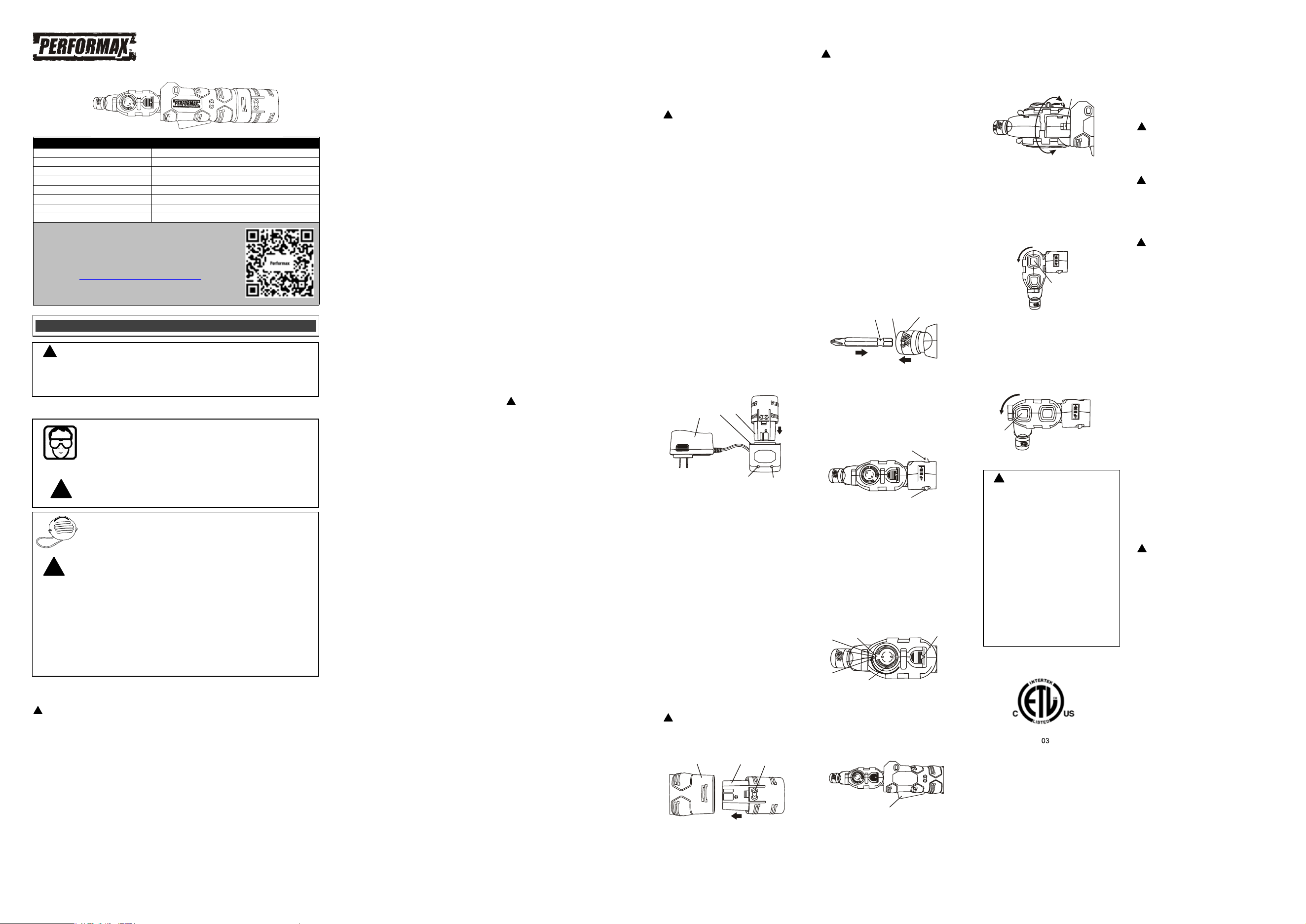
CHARGING THE BATTERY
WARNING: Use only the specified 8V
Li-ion charger and 8V Li-ion ba�ery with this
tool. Using any other charger or ba�ery may
damage the charger or the ba�ery,
and
possibly cause serious injury.
1. To charge the ba�ery, place the charger (1)
in a dry loca�on near a 120 V AC, 60 Hz
electrical outlet (Fig. 1).
2. Plug the ba�ery charger into the 120 V AC,
60 Hz wall receptacle. The green LED (4) will
turn ON.
3. Place the ba�ery stem (2) into the matching
cavity (3) in the top of the charging base.
NOTES:
a) Make sure the ba�ery is pressed fully
onto the charging base as far as it will go.
b) Do NOT cha
rge ba�eries when the work
area or the ba�ery temperature is at or
below 0°C (32° F) or above 45°C (113° F).
When the ba�ery charger is plugged into a
“live” receptacle, the ba�ery charger will begin
charging the ba�ery. The red LED (5) will turn
ON indica�ng the ba�ery is being charged.
When the ba�ery is fully charged, the red LED
will turn OFF and the green LED will turn ON.
NOTE: A completely discharged ba�ery will
take approximatel
y 2 hours to become fully
charged.
ASSEMBLY AND OPERATION
INSTALLING A BATTERY IN THE TOOL
1. Remove the discharged ba�ery (1) from the
tool (2) by pressing on the ba�ery release
bu�ons (3) on the sides of the ba�ery
(Fig. 2).
2. Pull the ba�ery out of the tool handle.
3. Slide the fully charged ba�ery into the
matching cavity in the tool handle where the
discharged ba�ery has been removed.
4. Insert the fully charged ba�ery into the tool
ha
ndle. The ba�ery release bu�on will
“click” into place when the ba�ery is fully
installed.
NOTE: The ba�ery can only be inserted into
the handle one way. If it will not slide into
the handle, rotate the ba�ery 180°.
WARNING: Do not immerse the ba�ery
pack in water. Sudden cooling could cause the
hot ba�ery to explode or leak. Water will also
damage the PCB.
INSTALLING A SCREWDRIVER BIT
WARNING: Never hold the screwdriver
with your fingers near the
switch while
changing the screwdriver bits. Accidentally
touching the switch may start the tool and
possibly cause an injury.
1. Pull outward on the quick release collar (1)
(Fig. 3).
2. Insert the grooved end of the bit (2) into the
bit holder (3).
NOTES:
a) Always use ANSI single ended screwdriver
bits with the grooved end. These bits will be
properly held in place by the collet. Other bit
types cannot be properly secured in the collet.
b) Push
the screwdriver bit as far as it will go
into the collet.
3. Release the quick release collar.
4. Pull outward on the screwdriver bit to
ensure it is properly locked into the collet.
NOTES:
a) Use the largest size screwdriver bit that will
properly fit the screw head.
b) Make sure the screwdriver bit is in good
condi�on and is neither damaged nor worn.
FORWARD/REVERSE SWITCH
1. To drive screws, press the right hand side of
the switch (1) (Fig. 4
).
2. To remove screws, press the le� hand side
of the switch (2).
LED WORKLIGHT
1. To turn the LED worklight ON, rotate the LED
switch (1) to point the LED toward the
screwdriver bit (Fig. 5). To turn the LED OFF,
rotate the LED switch to the OFF posi�on
(2).
2. To replace the worklight ba�ery, slide the
ba�ery cover (3) back and remove the
ba�ery.
NOTE: The ba�ery is 3V Li-ion CR927.
VARIABLE SPEED TRIGGER SWITCH
To start the screwdriver r
ota�ng, squeeze the
trigger switch (1) (Fig. 6). The harder you
squeeze the trigger, the faster the screwdriver
will rotate.
MULTI-POSITION SCREWDRIVER HEAD
The screwdriver head can be rotated and
swiveled into many posi�ons to access screws
that are otherwise difficult to reach.
1. To rotate the head, push the head release
bu�on (1) forward (Fig. 7). While holding
the head release bu�on forward, rotate the
head to the desired posi�on. Re
lease the
head release bu�on and rotate the head
slightly un�l it locks into posi�on.
2. To change the angle of the driver head, push
the driver head release bu�on (1) (Fig. 8).
While holding the driver head release
bu�on, rotate the driver head to the desired
posi�on. Release the driver head release
bu�on and rotate the head slightly un�l it
locks into posi�on.
3. To change the angle of the connector, push
the connector bu�on (2) (Fig. 9). While
hol
ding the connector bu�on, rotate the
connector to the desired posi�on. Release
the connector bu�on and rotate the
connector slightly un�l it locks into posi�on.
MAINTENANCE
GENERAL
DO NOT use solvents when cleaning plas�c
parts. Plas�cs are suscep�ble to damage from
various types of commercial solvents and may
be damaged by their use. Use a clean cloth to
remove dirt, dust, oil, grease etc.
WARNING: Do not allow brake fluids,
gasoli
ne, petroleum-based products,
penetra�ng oils, etc. to come into contact with
plas�c parts. They contain chemicals that can
damage, weaken or destroy plas�c.
WARNING: When cleaning the tool with
compressed air, always wear safety goggles.
Flying debris can cause serious eye damage.
DO NOT abuse power tools. Abusive prac�ces
can damage the tool and the workpiece.
WARNING: DO NOT a�empt to modify
tools or create accessories. Any such
altera�on
or modifica�on is misuse and could result in a
hazardous condi�on leading to possible serious
injury. It will also void the warranty.
LITHIUM-ION BATTERY MAINTENANCE
Lithium-ion ba�eries do not have a “memory”
and do not require to be completely discharged
periodically. It is recommended that you
charge your Lithium-ion ba�eries a�er each
use so they will be fully charged when needed.
NOTE: A fully charged ba�ery will
lose about
2% of its charge per month during storage.
BATTERY PACK REMOVAL AND PREPARATION
FOR RECYCLING
To preserve our natural resources, please
recycle or dispose of ba�eries properly.
The ba�eries supplied with this tool may
contain chemicals and metals that are harmful
to the environment. Never dispose of
rechargeable ba�eries in your normal
household garbage or in landfill sites because
they will add to the pollu�on of the
environme
nt.
Consult your local waste authority for
informa�on regarding available recycling and
disposal op�ons.
WARNING: Upon removal of the ba�ery
pack, cover the terminals of the ba�ery pack
with electrical tape or heavy-duty adhesive
tape. Never touch both terminals with metal
objects or body parts, because a short circuit
may result. Keep away from children. Do not
a�empt to destroy or disassemble ba�ery pack
or remove any of
its components.
Rechargeable ba�eries must be recycled or
disposed of properly. Failure to comply with
these warnings could result in fire and serious
injury.
EYE, EAR, LUNG PROTECTION
PRODUCT SPECIFICATIONS
Speed: 0 – 175 RPM (no load)
Torque: 70 in. lbs.
Hex drive: Quick release ¼" (6.35 mm)
Ba�ery: 8 V, 2.0 Ah Lithium-ion
Ba�ery charger: 2 hour, Class 2
Charger input: 120 V AC, 60 Hz
Charger output: 9.1 V DC, 1.0 A (maximum)
Weight: 1 lb. 5 oz. (0.604 kg) with ba�ery
GENERAL SAFETY WARNINGS
8 VOLT LI-ION SCREWDRIVER
241-1360
!
!
!
!
!
WARNING: Before using this tool or any of its accessories, read this manual and
follow all Safety Rules and Opera�ng Instruc�ons. The important precau�ons, safeguards
and instruc�ons appearing in this manual are not meant to cover all possible situa�ons. It
must be understood that common sense and cau�on are factors which cannot be built into
the product.
!
!
ALWAYS WEAR EYE PROTECTION THAT CONFORMS WITH CSA
REQUIREMENTS or ANSI SAFETY STANDARD Z87.1
FLYING DEBRIS can cause permanent eye damage. Prescrip�on eyeglasses
ARE NOT a replacement for proper eye protec�on.
WARNING: Non-compliant eyewear can cause serious injury if broken
during the opera�on of a power tool.
WEAR A DUST MASK THAT IS DESIGNED TO BE USED WHEN
OPERATING A POWER TOOL IN A DUSTY ENVIRONMENT.
WARNING:
Dust that is created by power sanding, sawing, grinding, drilling,
and other construc�on ac�vi�es may contain chemicals that are known to
cause cancer, birth defects, or other gene�c abnormali�es. These chemicals
include:
Lead from lead-based paints
Crystalline silica from bricks, cement, and other masonry products
Arsenic and chromium from chemically treated lumber
The leve
l of risk from exposure to these chemicals varies, according to how
o�en this type of work is performed. In order to reduce exposure to these
chemicals, work in a well-ven�lated area, and use approved safety equipment,
such as a dust mask that is specifically designed to filter out microscopic
par�cles.
!
!
!
WARNING:
For safety reasons,
the operator must read the sec�ons of
this Owner’s Manual en�tled “GENERAL
SAFETY WARNINGS”, “POWER TOOL
SAFETY”, “SPECIFIC SAFETY RULES”, and
“BATTERY AND CHARGER SAFETY” before
using this screwdriver.
Every �me you use the screwdriver you
should verify the following:
1. Screwdriver bit is the correct type &
size, not worn and not damaged in
any way.
2. Workpiece is properly secured.
3. Safety glasses are be
ing worn.
Failure to adhere to these safety rules
can greatly increase the chances of
injury.
!
!
!
This symbol designates that this tool is listed with
Canadi
an and U.S. requirements by ETL Testing
Laboratories
, Inc. Conforms to UL STD. 60745-1,
60745
-2-2.
Certified
to CAD/CSA C22.2 No. 60745-1, 60745-2-
2.
LISTED
3042597
JD5 9
1
2
3
Fig. 3
Fig. 1
1
2
3
4
5
Fig. 2
3
1
2
Fig. 6
1
Need Assistance?
• Technical questions
• Replacement parts
• Parts missing from package
Email us at:
Call us on our toll-free customer support line:1-866-349-8665
(9-5pm Monday-Friday EST)
Scan here for support
PERFORMAX
®
8 VOLT LI-ION SCREWDRIVER WARRANTY
2-YEAR LIMITED WARRANTY:
This PERFORMAX
®
brand power tool carries a 2-Year Limited Warranty to the
original purchaser. If, during normal use, this PERFORMAX
®
power tool breaks
or fails due to a defect in material or workmanship within two (2) years from the
date of original purchase, simply bring this tool with the original sales receipt
back to your nearest MENARDS® retail store. At its discretion, PERFORMAX
®
agrees to have the tool or any defective part(s) repaired or replaced with the
same or similar PERFORMAX
®
product or part free of charge, within the stated
warranty period, when returned by the original purchaser with original sales
receipt. Not withstanding the foregoing, this limited warranty does not cover any
damage that has resulted from abuse or misuse of the Merchandise. This
warranty: (1) excludes expendable parts including but not limite
d to blades,
brushes, belts, bits, light bulbs, and/or batteries; (2) shall be void if this tool is
used for commercial and/or rental purposes; and (3) does not cover any losses,
injuries to persons/property or costs. This warranty does give you specific legal
rights and you may have other rights, which vary from state to state. Be careful,
tools are dangerous if improperly used or maintained. Seller’s employees are
not qualified to advis
e you on the use of this Merchandise. Any oral
representation(s) made will not be binding on seller or its employees. The rights
under this limited warranty are to the original purchaser of the Merchandise and
may not be transferred to any subsequent owner. This limited warranty is in lieu
of all warranties, expressed or implied including warranties or merchantability
and fitness for a particular purpose. Seller shall not be liable for any specia
l,
incidental, or consequential damages. The sole exclusive remedy against the
seller will be for the replacement of any defects as provided herein, as long as
the seller is willing or able to replace this product or is willing to refund the
purchase price as provided above. For insurance purposes, seller is not allowed
to demonstrate any of these power tools for you.
For questions / comments, technical assistance or repair parts –
Please Call Toll F
ree at: 1-866-349-8665 (9-5pm Monday-Friday EST)
Or email us at: customerservice@powertoolsplus.ca
SAVE YOUR RECEIPTS. THIS WARRANTY IS VOID WITHOUT THEM.
Distributed by: Menard, Inc., Eau Claire, WI 54703
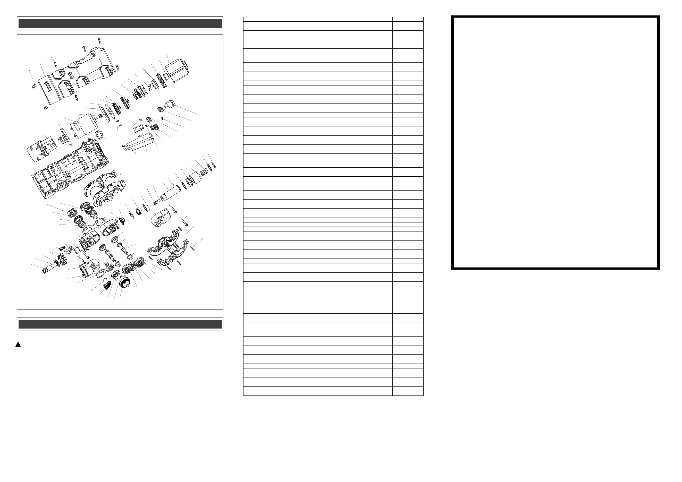
EXPLODED VIEW
PARTS LIST
WARNING: When servicing, use only original equipment replacement parts. The use of any
other parts may create a safety hazard or cause damage to the tool.
Any a�empt to repair or replace electrical parts on this tool may create a safety hazard unless
repairs are performed by a qualified technician. For more informa�on, call the Toll-free Helpline,
at 1-866-349-8665.
Always order by PART NUMBER, not by key numbe
r.
!
Key #
Part #
Part Name
Quantity
1
2050080181
Retaining ring
1
2
2030020310
Washer
1
3
2050060221
Spring
1
4
2040170008
Ring
1
5
3150160200
Spacer
1
6
2030020310
Washer
1
7
4080120001
Detent 2.5 ball
1
8
2010120009
Spindle
1
9
2040160208
Sleeve
1
10
2050060249
Spring
1
11
2010080132
Washer
1
12
4010010144
Bearing
1
13
2030020353
washer
1
14
2010200033
Connecting plug
1
15
2010030008
Bevel gear 3
1
16
2020170020
Front swivel head
1
17
2020170021
Intermediate rotating head
1
18
2010080134
Washer
1
19
3120020148
Lock button
1
20
2050040058
Spring
1
21
2010190012
Pre-set head positioner
1
22
2010030006
Bevel gear 1
1
23
2030020324
Gasket
1
24
2040290092
Output shaft
1
25
2010030007
Bevel gear 2
2
26
2030020352
Gasket
4
27
2040290091
Transmission shaft
2
28
2010080133
Washer
4
29
2030030279
Bearing housing
1
30
2010010140
Transmission gear 1
2
31
2010010141
Transmission gear 2
1
32
4110030028
Sleeve
1
33
4100040010
E circlip
1
34
3150160201
LED seat
1
35
1220040020
LED
1
36
2030150061
Sliding contacts
2
37
3150160203
Switch plate
1
38
3160090093
Battery sliding cover
1
39
1260040002
Battery
1
40
1130040061
LED board
1
41
2030150064
Shell
2
42
4030010232
ST2.5*5
1
43
2030030278
Frame for stepped lock assembly
1
44
2050060222
Spring
2
45
2010190011
Lock block
2
46
3120020138
Lock knob 1
1
47
3120020137
Lock knob 2
1
48
3160100015
Support assembly
1
49
3120010092
Switch button
1
50
1130010225
PCB
1
51
2030160135
Spacer
1
52
2030150062
Sliding contact
1
53
2050040059
Spring
1
54
3150160202
Contact seat
1
55
2050060223
Spring
1
56
3120120141
Reverse speed push button
1
57
1130030051
Switch PCB
1
58
1290030002
Battery housing
1
59
1130030052
Battery contact assembly
1
60
1039010019
Motor
1
61
2010010114
Motor pinion gear
1
62
3150090053
Motor flange
1
63
2030020314
Washer
1
64
2010010115
Planetary gear
3
65
1170070082
Planetary carrier
1
66
1170070083
Planetary carrier
1
67
2010010116
Planetary gear
6
68
1170070084
Planetary carrier
1
69
4110090001
Spindle lock pins
6
70
2010230016
Spindle lock disk
1
71
2010240045
Driving block
1
72
2010080120
Sleeve
1
73
2010090074
Gear box
1
74
2030090032
U clips
2
75
3010030032
Housing
1
76
4030010034
Screw ST2.9*16
5
77
3110010231
Decorative plates
1
78
4020010055
Screw ST2.5*5
2
79
4030010236
ST2.5*6
1
80
4020010180
M3*20
4
81
4030010130
ST2.9*25
2
82
4030010028
ST2.9*12
5
Rev 1.6 15/07/2025
1
2
3
4
5
6
7
8
9
10
11
12
13
14
15
16
17
18
19
20
21
22
23
24
25
26
27
28
29
30
31
32
33
34
35
36
37
38
39
40
41
42
43
44
45
46
47
48
49
50
51
52
53
54
55
56
57
59
60
61
62
63
64
65
66
67
68
69
70
71
72
73
74
75
76
77
78
79
80
81
82
58