pnuew
-rUEkJlU
S,&3UMO
vos/vowscda
YCINOH

Thank you for purchasing a Honda
Outboard Motor.
This manuul describes the operation
and maintenance of the Honda
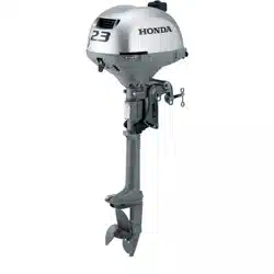
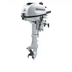
BF3SA
and
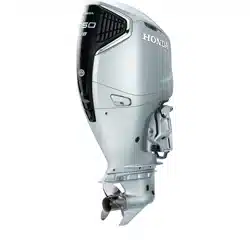
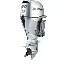
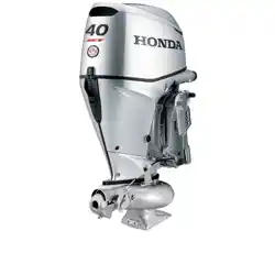
BF4OA and BFWA Out-
board Motors.
All information in this publication is
hased
on
the latest product informa-
tion available at the time of printing.
Honda Motor Co.. Ltd. reserves the
right to make changes at any time
without notice and without incurring
any obligation.
No part of this publication may be
reproduced without written
permission.
This manual should be considered a
permanent part of the Outboard Motor
and it must stay with the Outboard
Motor if resold.
READ THIS OWNER’S MANUAL
CAREFULLY. Pay special attention to
these symbols and any instructions
that follow.
m
You WILL be
KILLED or SERIOUSLY HURT
if you don’t follow instructions.
B You CAN be
KILLED or SERIOUSLY HURT
if you don’t follow instructions.
-
You CAN be HURT
if you don’t follow instructions.
NOTICE 1 Your outboard motor
or other property can be damaged
if you don’t follow instructions.
Honda Outboard Motors are designed
to give safe and dependable service if
operated according to instructions.
Operating this Outboard Motor
requires special effort on your part to
ensure your-safety and the safety of
others.
-
Careless operation
or misuse may cause injury or
property damage. Read and
understand this owner’s manual
before operating the Outboard
Motor.
If a problem should arise, or if you
have any questions about your
Outboard Motor, see an authorized
Honda Marine dealer.
HONDA MOTOR CO., LTD. 1994,
ALL RIGHTS RESERVED
1
TYPES OF HONDA BF35A/40A/5OA OUTBOARD MOTORS
It may hc necessary to rcfcr to this chart for reference purposes when reading this manual.
TYPE CODE (example)
L R T T = Power Trimmilt
R = Remote Control H = Tiller Handle
TT-II
X = Extra Long Shaft L = Long Shaft
2
IDENTIFICATION NUMBERS
RIGHT STERN BRACKET
, ,-in,
PRODUCT IDEliTiFICATION NUMBER
Record the Product Identification
Number (P.I.N.)
and the Engine Serial
Number for your reference. Refer to
the Product Identification Number
when
ordering parts, and when mak-
ing technical or warranty inquiries
(see page 101).
STARTER MOTOR
- -\
The Product Identification Number is
stamped on a plate and attached to the
right stern bracket. The Engine Serial
Number is stamped on the cylinder
block under the starter motor which is
located in the front of the engine.
Product identification number:
Engine serial number:
3
CONTENTS
1. SAFETY
SAFETY LABELS..
................................................... 6
SAFETY INFORMATION
........................................ 7
2. COMPONENT IDENTIFICATION
............................
8
3. CONTROLS
TILLER HANDLE TYPE
Engine Start Button
.................................................... 1 I
Shift Lever..
................................................................
II
Choke Knob.. ..............................................................
1 I
Throttle Grip.. .............................................................
12
Throttle Opening Indicator
.........................................
12
Throttle Friction Knob
...............................................
12
Engine Stop Switch
....................................................
13
Emergency Stop Switch
Lanyard
...............................
13
Oil Pressure Indicator Light
.......................................
I4
Overheat Indicator Light
............................................ 14
REMOTE CONTROL TYPE
Remote Control Lever
................................................ 15
Neutral Release Lever
................................................
I6
Ignition Switch
........................................................... I6
Emergency Stop Switch
Lanyard
............................... I7
Choke/Fast Idle Lever
................................................
18
Manual Choke Knob
......... .........................................
18
Oil Pressure Indicator Light/Buzzer..
.........................
19
Overheat Indicator Light/Buzzer
................................ I9
REMOTE CONTROL & PQWER TRIM/TILT TYPE
Power Trim/Tilt Switch (remote control lever)
.......... 20
Power Tilt Switch (motor pan)
...................................
2 I
4
Trim Meter
.................................................................
21
Tachometer
.................................................................
2 I
Manual Relief Valve
..................................................
22
GAS ASSISTED TILT TYPE
Tilt Lever
.................................................................... 22
CONTROLS & INSTRUMENTS (common)
Tilt Lock
Lever.. .........................................................
23
Trim Tab..
...................................................................
23
Anode Metal
...............................................................
24
Cooling
System
Indicator..
.........................................
24
Water
Intakes..
............................................................
25
Transom Angle Adjusting Rod
..................................
26
Fuel Cap/Gauge/Vent
Knob
.......................................
27
Over-Rev Limiter
.......................................................
27
4. PRE-OPERATION CHECKS
Engine Cover Removal/Installation
...........................
28
Engine
Oil
..................................................................
29
Fuel Level..
.................................................................
30
Fuel Recommendations
..............................................
3 1
Oxygenated Fuels
.......................................................
32
Propeller and Cotter pin
.............................................
33
Steering Friction Adjustment (common).
................... 33
Remote Control
Friction
Adjustment
.........................
34
Other Checks
l
Stern
bracket
............................................................
34
l
Tool Kit
....................................................................
34
l
Anodes
.....................................................................
34
5. STARTING THE ENGINE
Fuel Tank and Vent Knob
..........................................
35
CONTENTS
Fuel Line Connection
................................................. 35
STARTING THE ENGINE (TILLER HANDLE TYPE).
... 37
STARTING THE ENGINE (REMOTE CONTROL TYPE). ...
41
Emergency Starting ....................................................
44
Troubleshooting Starting Problems.. ..........................
49
6. OPERATION
Break-in Procedure.. ...................................................
50
TILLER HANDLE TYPE
Gear Shifting
......................................................... 5 1
Steering ..................................................................
52
Cruising .................................................................
52
REMOTE CONTROL TYPE
Gear Shifting
......................................................... 53
Cruising .................................................................
54
Tilting motor
GAS ASSISTED TILT TYPE..
............................. 55
POWER TRIM/TILT TYPE
................................. 58
POWER TRIM/TILT TYPE
Trim Meter .............................................................
59
Power Tilt Switch (Motor Pan)
............................. 60
Manual Relief Valve..
............................................ 60
Tilt Lock Lever
...................................................... 6 1
Trim Tab Adjustment
................................................. 62
MOTOR PROTECTION SYSTEM
Engine Oil Pressure and
Overheat Warning
System.. ................................... 63
Over-Rev Limiter
.................................................. 65
Power Trim Wgning System
................................ 65
Anodes ................................................................... 66
Shallow Water Operation ...................................... 67
High Altitude Operation ........................................ 68
7. STOPPING THE ENGINE
TILLER HANDLE TYPE ..................................... 69
REMOTE CONTROL TYPE ................................ 7 1
8. TRANSPORTING
.....................................................
72
9. CLEANING AND FLUSHING
................................. 73
10. MAINTENANCE..
..................................................... 75
Tool Kit and Spare Parts.. ...................................... 76
MAINTENANCE SCHEDULE ............................ 77
Engine Oil .............................................................. 79
Gear Oil ................................................................. 8 I
Spark Plugs ............................................................ 83
Battery (not included). ........................................... 84
Lubrication ............................................................ 86
Engine Fuel Filter .................................................. 87
Fuel Tank and Filter .............................................. 89
Fuse Replacement.. ................................................ 90
Propeller ................................................................ 9 1
Submerged Motor .................................................. 92
I 1. STORAGE
................................................................. 94
12. TROUBLESHOOTING
............................................. 96
13. SPECIFICATIONS
.................................................... 98
14. WARRANTY
SERVICE ........................................... 101
15. WIRING
DIAGRAM ................................................. 102
. 16. INDEX
....................................................................... I05
5
1. SAFETY
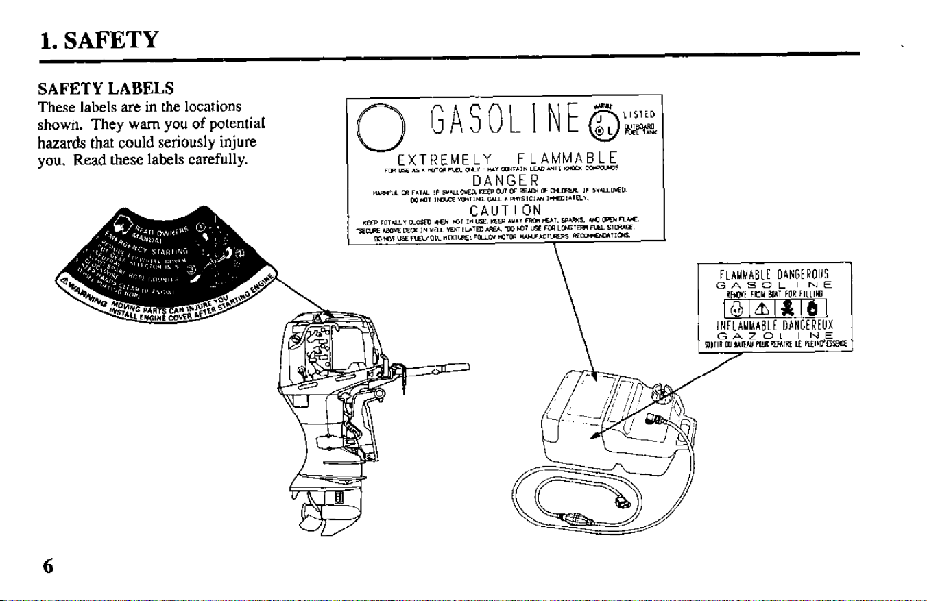
SAFETYLABELS
These labels are in the locations
show& They warn you of potential
hazards that could seriously injure
you. Read these labels carefully.
EXTREMELY
FLAMMABLE
FUI USE As A lwu1 FIEI. ma.” -#+A” omT,IN EM UlTl twa coparm
6
1. SAFETY
SAFETY INFORMATION
For your safety and the safety of oth-
ers, pay special attention to these pre-
cautions.
Operator Responsibility
-Know how to stop the engine
quickly in case of emergency.
Understand the use of all controls.
Do not exceed the boat manufactur-
er’s power recommendation, and be
sure that the outboard motor is
properly mounted.
Never permit anyone to operate the
outboard motor without proper
instruction.
Stop the engine immediately if any
one falls overboard.
Do not run the motor while the
boat is near anyone in the water.
Attach the emergency stop switch
lanyard securely to the operator.
Do
not remove the engine cover
while the engine is running.
l
Before operating the outboard
.motor, familiarize yourself with all
laws and regulations relating to
boating and the use of outboard
motors.
l
Do not attempt to modify the out-
board motor.
l
Always wear PERSONAL
FLOTATION DEVICE (PFD) when
on board.
l
Do not remove any guards, labels,
shields, covers or safety devices;
they are installed for your safety.
Fire and Burn Hazards
Gasoline is extremely flammable, and
gasoline vapor can explode. Use
extreme care when handling gasoline.
l
Remove the fuel tank from the boat
for refueling.
l
Refuel in a well-ventilated area
with the engine stopped. Keep
flames and sparks away, and do not
smoke in the area.
l
Refuel carefully to avoid spilling
fuel. Avoid overfilling the fuel tank
(there should be no fuel in the filler
neck). After refueling, tighten the
filler cap securely. If any fuel is
spilled, make sure the area is dry
before starting the engine.
7

2. COMPONENT IDENTIFICATION (TILLER HANDLE TYPE)
THROTTLE GRIP
\
FUEL LINE
CONNECTOR
I
ENGINE COVER
OIL FILLER CAP
OIL LEVEL
GEAR SHIFT LEVER
LEVER
I IP
STERN
IV,
ENGINE OIL
U.-I
[ ANTI-VENTILATION
TRANSOM
ANGLE
GEAR OIL
LEVEL PLUG
(ANODE METAL)
PROPELLER
\
THROTTLE
FRICTION K
ENGINE START
BUTTON
\
TILT LEVER
WATER INTAKE
OIL
.NOB
.---
a
/
PRESSURE INDICATOR LIGHT
\
OVERHEAT
INDICATOR
LIGHT
CHOKE KNOB
/ I
\
EMERGENCY
STOP SWITCH
EMERGENCY
LANYARD
STOP SWITCH
CLIP
SPARE EMERGENCY
STOP SWITCH CLIP
GEAR OIL DRAIN PLUG
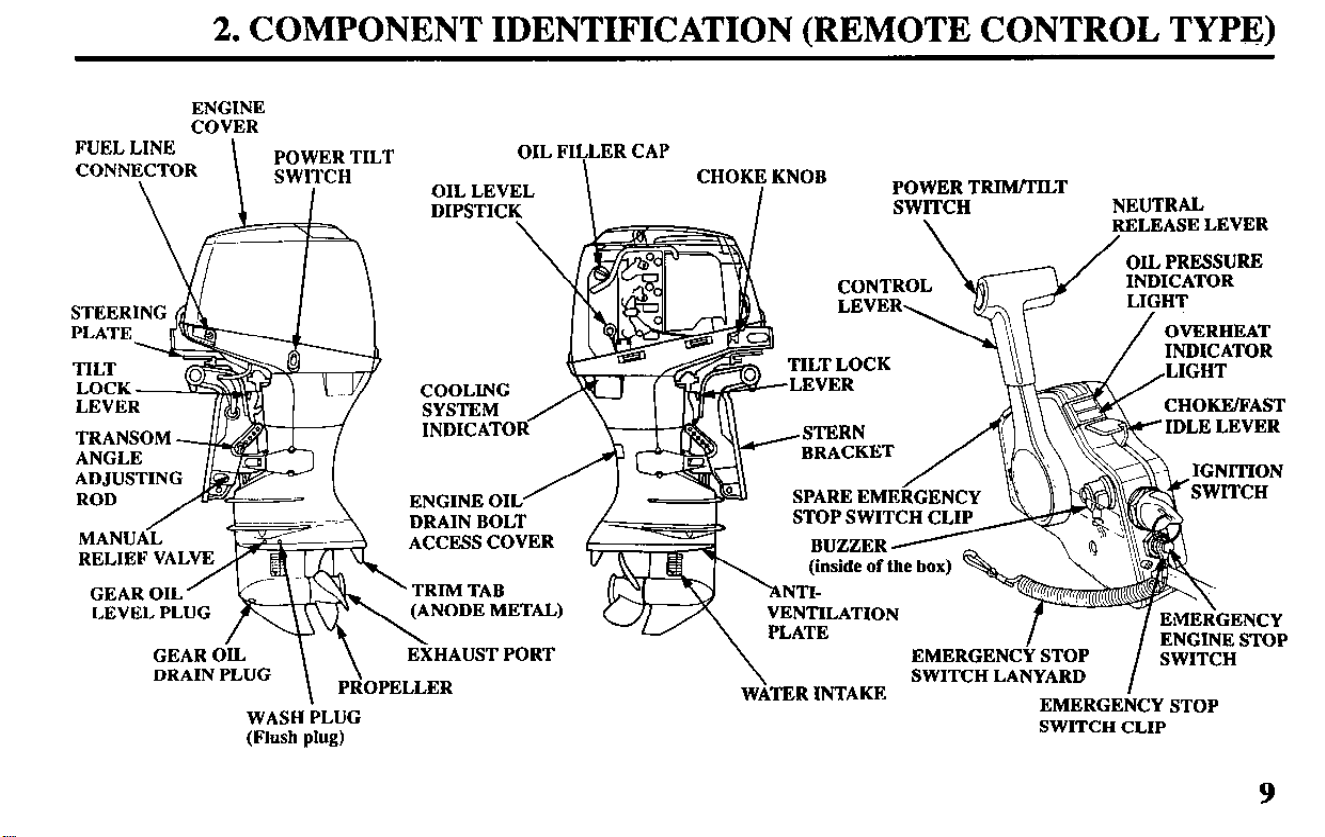
2. COMPONENT IDENTIFICATION (REMOTE CONTROL TYPE)
ENGINE
COVER
FUEL LINE
CONNECTOR
POWER TILT
\
SWITCH
I
ENGINE OIL
/
M ANUA<
DRAIN BOLT
ACCESS COVER
RELIEF VALV
OIL FI$LER CAP
OIL LEVEL
DIPSTIC
POWER TRIM/TILT
SWITCH
NEUTRAL
Fgi;fzL~gi;g
/
OVERHEAT
“DICATOR In
LIGHT
COOLING
LEVEK
SYSTEM
INDICATOR
GEAR OIL
LEVEL PL
ETAL)
GEAR OIL
\
\
EXHAUST PORT
DRAIN PLUG
PROPELLER
WASH PLUG
(Flush plug)
CHOKE/FAST
IDLE LEVER
STOP SWITCH CL1
EMERGENCY STOP
ENGINE STOP
\
SWITCH LANYARD
WATER INTAKE
EMERGENCY STOP
SWITCH CLIP
9
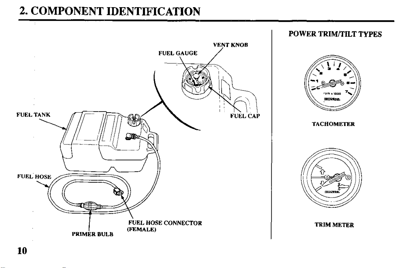
2. COMPONENT IDENTIFICATION
VENT KNOB
FUEL GAUGE
FUEL CAP
FUEL T
FUEi
I
FUEL HOSE CONNECTOR
PRIMER BULB
(FEMALE)
10
POWER TRIM/TILT TYPES
TACHOMETER
TRIM METER
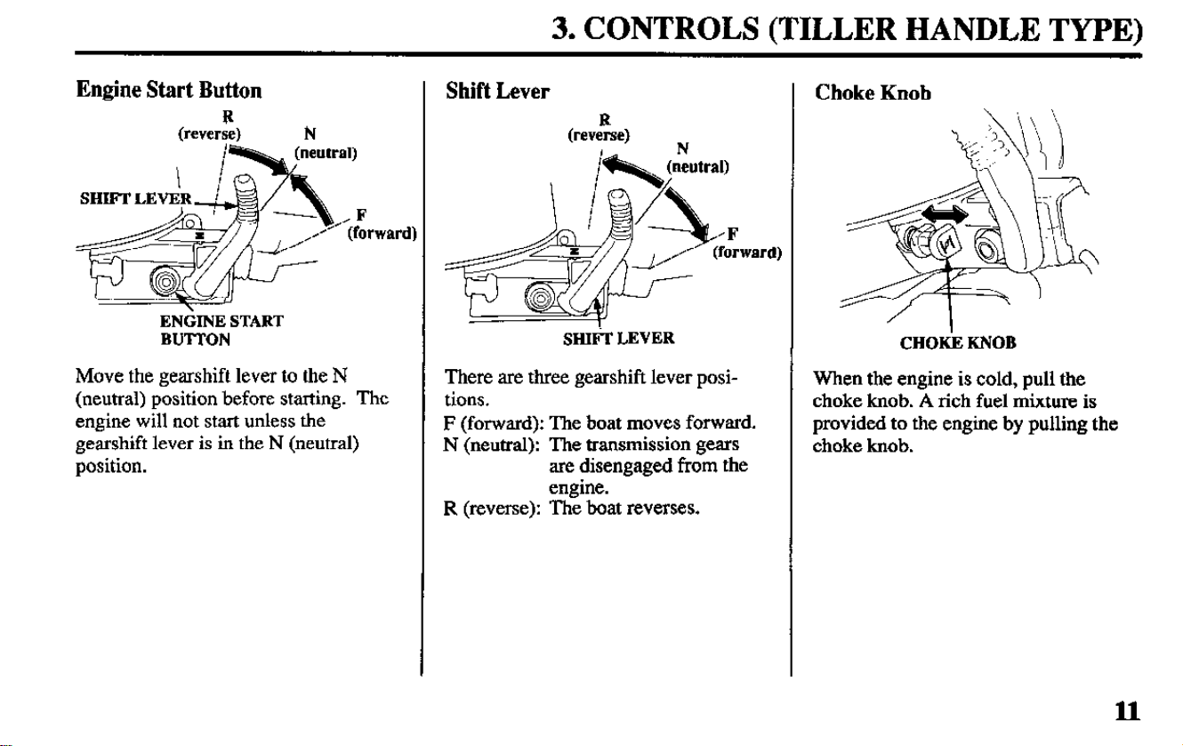
3. CONTROLS (TILLER HANDLE TYPE)
Engine Start Button
R
(reverse) N
ENdINE START
BUTTON
Move the gearshift lever to the N
(neutral) position before starting. The
engine will not start unless the
gearshift lever is in the N (neutral)
position.
Shift Lever
(reveZse)
N
SHIti LEVER
There are three gearshift lever posi-
tions.
F (forward): The boat moves forward.
N (neutral): The transmission gears
are disengaged from the
engine.
R (reverse): The boat reverses.
Choke Knob
CHOti KNOB
When the engine is cold, pull the
choke knob. A rich fuel mixture is
provided to the engine by pulling the
choke knob.
11
3. CONTROLS (TILLER HANIDLE TYPE)
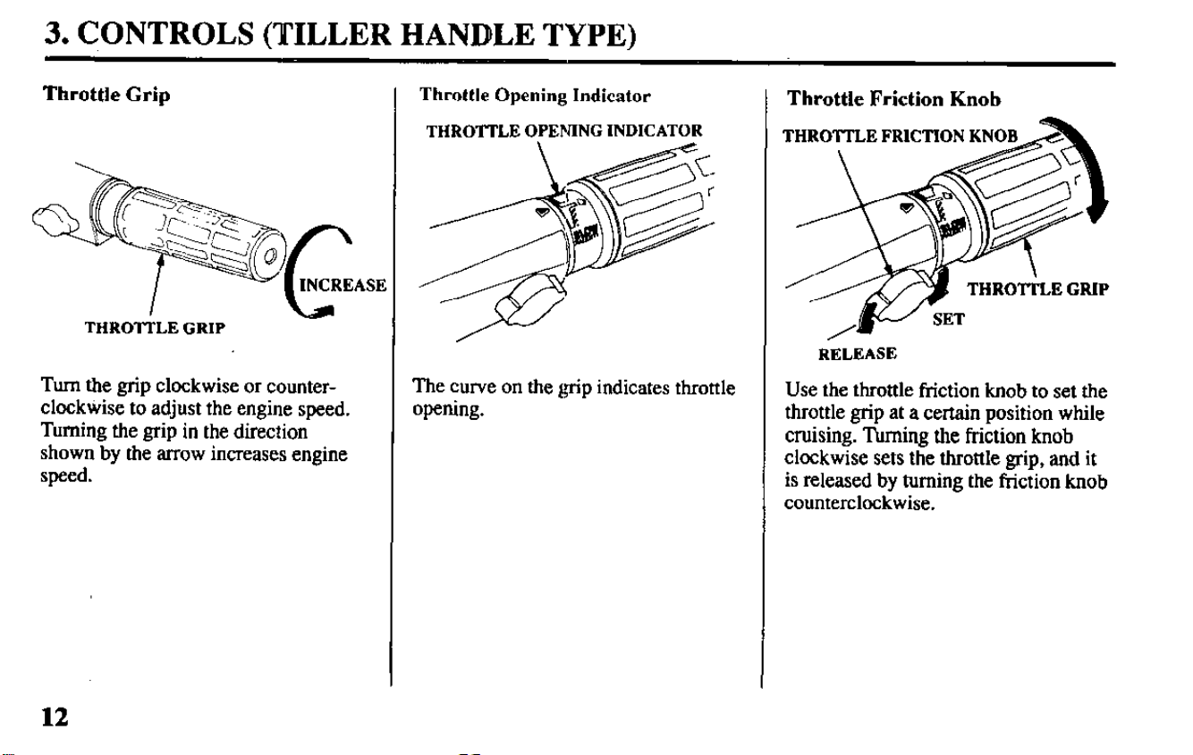
Throttle Grip
THRO’ITLE GRIP
Turn the grip clockwise or counter-
clocktiise to adjust the engine speed.
Turning the grip in the direction
shown by the arrow increases engine
speed.
Throttle Opening Indicator
THROTTLE OPENING INDICATOR
The curve on the &tip indicates throttle
opening.
Throttle Friction Knob
THROTI’LE FRICTION KNO
RELEASE
Use the throttle friction knob to set the
throttle grip at a certain position while
cruising. Turning the friction knob
clockwise sets the throttle grip, and it
is released by turning the friction knob
counterclockwise.
12
3. CONTROLS (TILLER HANDLE TYPE)
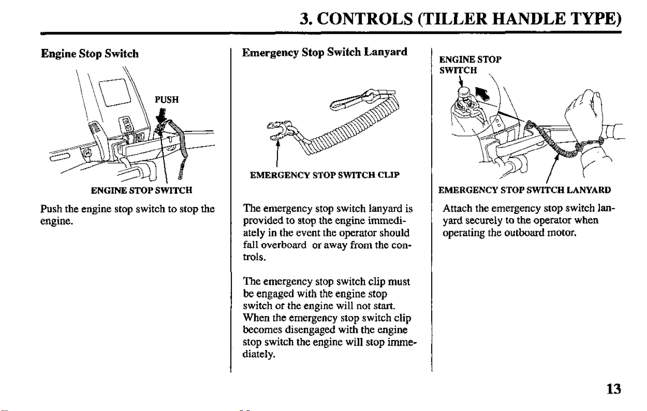
Engine Stop Switch
ENGINE STOP SWITCH
Push the engine stop switch to stop the
engine.
Emergency Stop Switch Lanyard
EMERGENCY STOP SWITCH CLIP
The emergency stop switch lanyard is
provided to stop the engine immedi-
ately in the event the operator should
fall overboard or away from the con-
trols.
The emergency stop switch clip must
be engaged with the engine stop
switch or the engine will not start.
When the emergency stop switch clip
becomes disengaged with the engine
stop switch the engine will stop imme-
diately.
ENGINE STOP
SWITCH
EMERGENCY STOP SWITCH LANYARD
Attach the emergency stop switch lan-
yard securely to the operator when
operating the outboard motor.
13
3. CONTROLS (TILLER HANDLE TYPE)
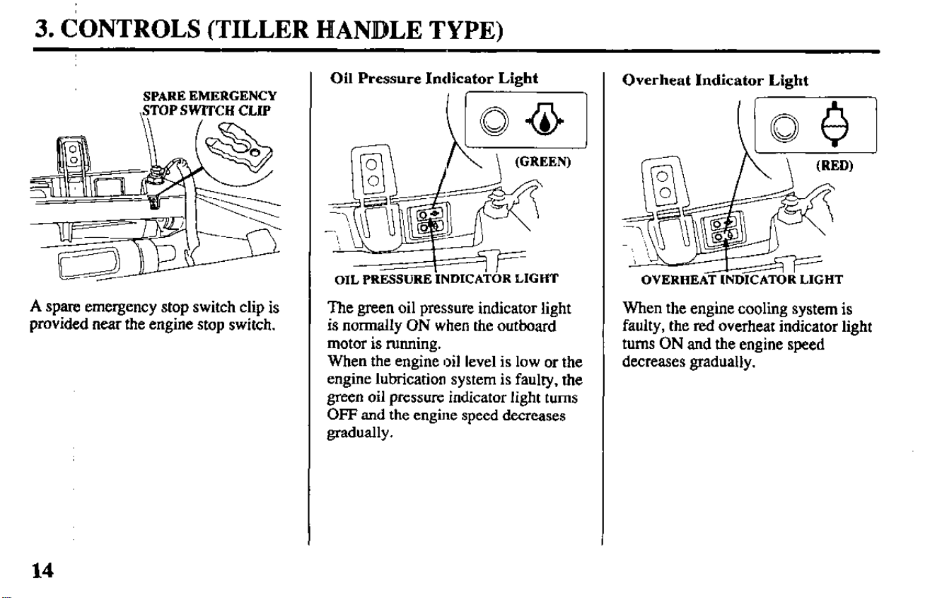
SPARE EMERGENCY
,STOP SWITCH CLIP
A spare emergency stop switch clip is
provided near the engine stop switch.
Oil Pressure Indicator Light
f-
OIL PRESSURE INDICATOR LIGHT
The green oil pressure indicator light
is normally ON when the outboard
motor is running.
When the engine oil level is low or the
engine lubrication system is faulty, the
green oil pressure indicator light turns
OFF and the engine speed decreases
gradually.
Overheat Indicator Light
OVERHEAT INDICATOR LIGHT
When the engine cooling system is
faulty, the red overheat indicator light
turns ON and the engine speed
decreases gradually.
14
3. CONTROLS (REMOTE CONTROL TYPE)
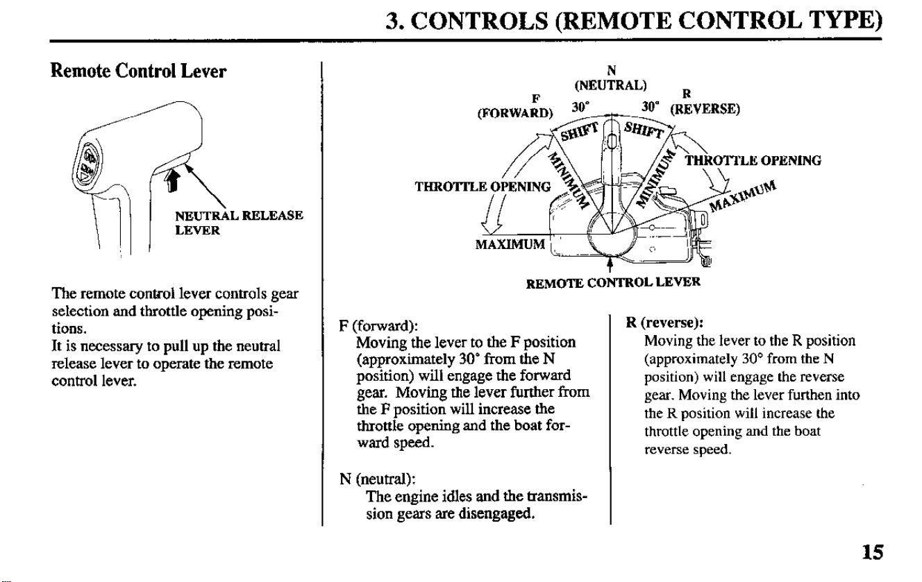
Remote Control Lever
The remote control lever controls gear
selection and throttle opening posi-
tions.
It is necessary to pull up the neutral
release lever to operate the remote
control lever.
THROm
D
(NEUiRAL, R
REMOTE CONTROL LEVER
F (forward):
Moving the lever to the F position
(approximately 30’ from the N
position) will engage the forward
gear. Moving the lever further from
the F position will increase the
throttle opening and the boat for-
ward speed.
N (neutral):
The engine idles and the transmis-
sion gears are disengaged.
R (reverse):
Moving the lever to the R position
(approximately 30” from the N
position) will engage the reverse
gear. Moving the lever furthen into
the R position will increase the
throttle opening and the boat
reverse speed.
15
3. CONTROLS (REMOTE CONTROL TYPE)
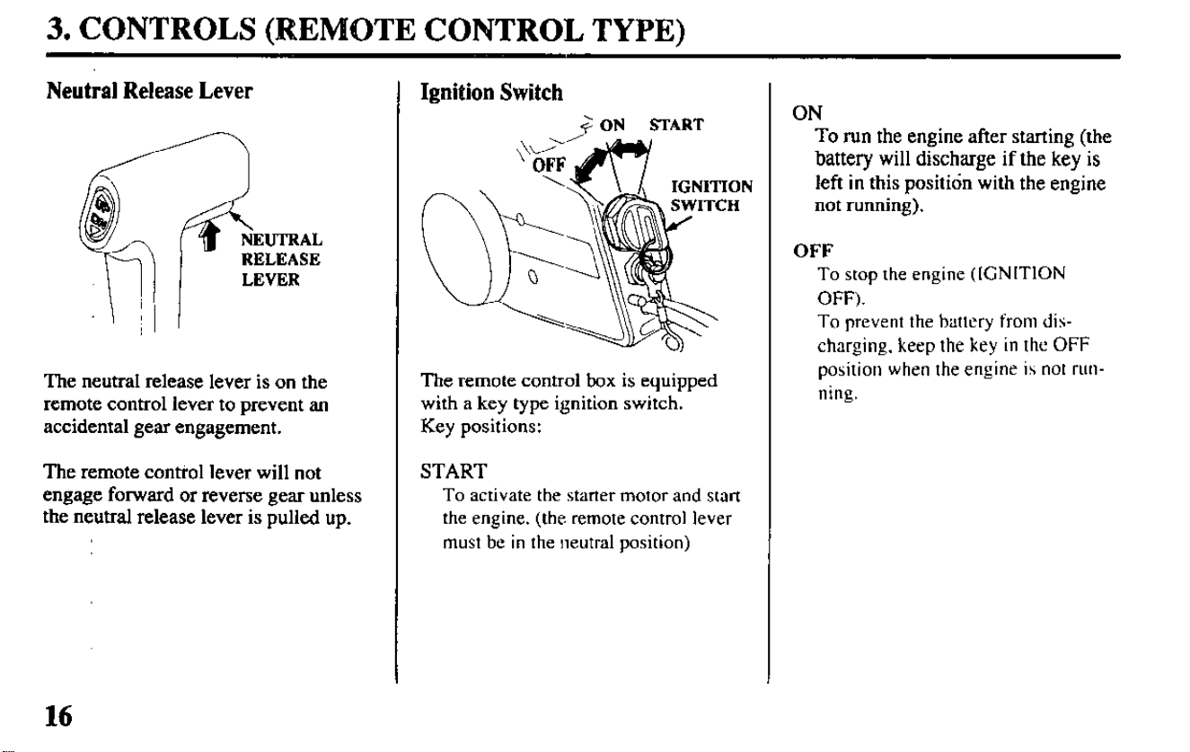
Neutral Release Lever
The neutral release lever is on the
remote control lever to prevent an
accidental gear engagement.
The remote control lever will not
engage forward or reverse gear unless
the neutral release lever is pulled up.
Ignition Switch
+ ON
START
The remote control box is equipped
with a key type ignition switch.
Key positions:
START
To activate the starter motor and start
the engine.
(the remote control lever
must be in the neutral position)
ON
To run the engine after starting (the
battery will discharge if the key is
left in this positidn with the engine
not running).
OFF
To stop the engine (IGNITION
OFF).
To prevent the battery from dis-
charging, keep the key in the OFF
position when the engine is not run-
ning.
16
3. CONTROLS (REMOTE CONTROL TYPE)
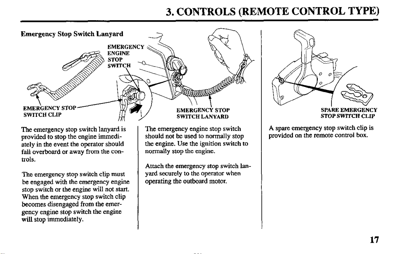
Emergency Stop Switch Lanyard
4
The emergency stop switch lanyard is
provided to stop the engine immedi-
ately in the event the operator should
fall overboard or away from the con-
trols.
The emergency stop switch clip must
be engaged with the emergency engine
stop switch or the engine will not start.
When the emergency stop switch clip
becomes disengaged from the emer-
gency engine stop switch the engine
will stop immediately.
The emergency engine stop switch
should not he used to normally stop
the engine. Use the ignition switch to
normally stop the engine.
Attach the emergency stop switch lan-
yard securely to the operator when
operating the outboard motor.
SPA’RE EMERGENCY
STOP SWITCH CLIP
A spare emergency stop switch clip is
provided on the remote control box.
17
3. CONTROLS (REMOTE CONTROL TYPE)
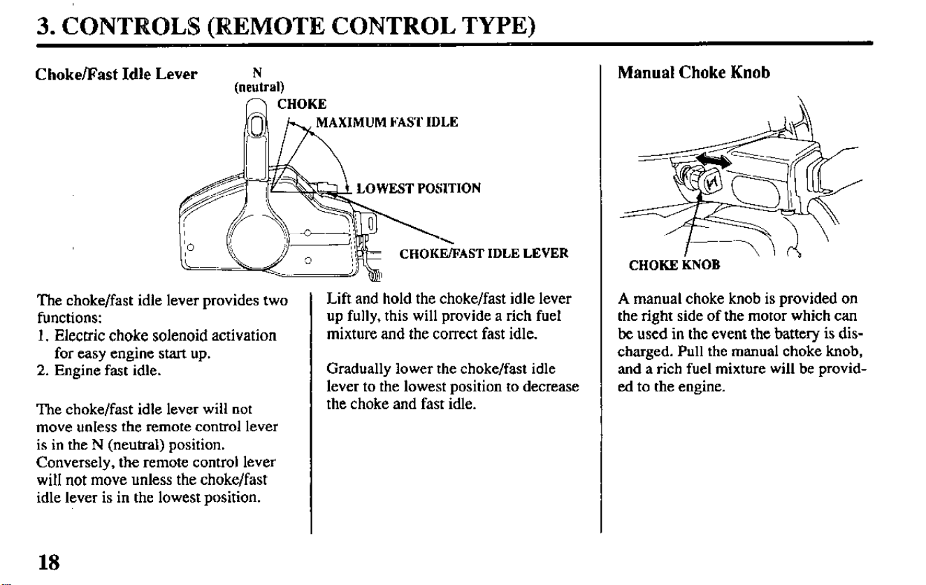
Choke/Fast Idle
Lever
f’-J CHOKE
XIMUM FAST IDLE
OWEST POSITION
&AST
The choke/fast idle lever provides two
functions:
1. Electric choke solenoid activation
for easy engine start up.
2. Engine fast idle.
The choke/fast idle lever will not
move unless the remote control lever
is in the N (neutral) position.
Conversely, the remote control lever
will not move unless the choke/fast
idle lever is in the lowest position.
IDLE LEVER
Lift and hold the choke/fast idle lever
up fully, this will provide a rich fuel
mixture and the correct fast idle.
Gradually lower the choke/fast idle
lever to the lowest position to decrease
the choke and fast idle.
Manual Choke Knob
CHOKE KNOB
A manual choke knob is provided on
the right side of the motor which can
be used in the event the battery is dis-
charged. Pull the manual choke knob,
and a rich fuel mixture will be provid-
ed to the engine.
18
3. CONTROLS (REMOTE CONTROL TYPE)
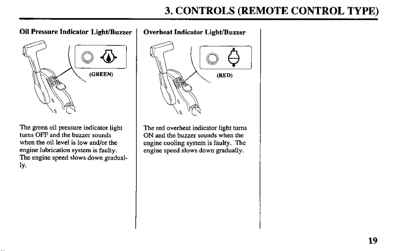
Oil Pressure Indicator Light/Buzzer
The green oil pressure indicator light
turns OFF and the buzzer sounds
when the oil level is low and/or the
engine lubrication system is faulty.
The engine speed slows down gradual-
ly-
Overheat Indicator Light/Buzzer
The red overheat indicator light turns
ON and the buzzer sounds when the
engine cooling system is faulty. The
engine speed Slows down gradually.
19
3. CONTROLS (REMOTE CONTROL & POWER TRIM/TILT TYPE)
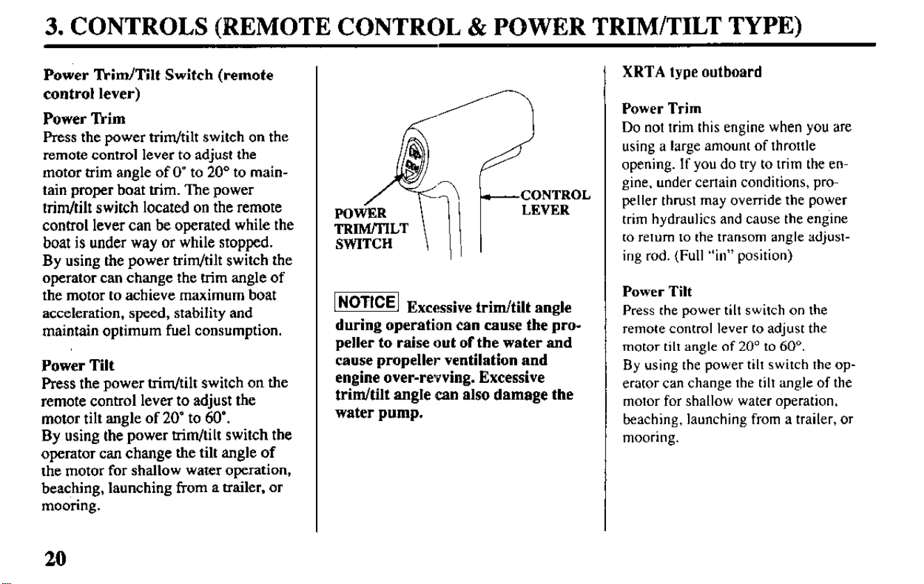
Power ‘l’kim/Tilt Switch (remote
control lever)
Power Tkim
Press the power trim/tilt switch on the
remote control lever to adjust the
motor trim angle of 0” to 20” to main-
tain proper boat trim. The power
trim/tilt switch located on the remote
control lever can be operated while the
boat is under way or while stopped.
By
using the power trim/tilt switch the
operator can change the trim angle of
the motor to achieve maximum boat
acceleration, speed, stability and
maintain optimum fuel consumption.
Power Tilt
Press the power trim/tilt switch on the
remote control lever to adjust the
motor tilt angle of 20” to 60’.
By
using the power trim/tilt switch the
operator can change the tilt angle of
the motor for shallow water operation,
beaching, launching from a trailer, or
mooring.
pi6Tzq
Excessive trim/tilt angle
during operation can cause the pro-
peller to raise out of the water and
cause propeller ventilation and
engine over-revving. Excessive
trim/tilt angle can also damage the
water pump.
XRTA type outboard
Power Trim
Do not trim
this engine when you are
using a large amount of throttle
opening. If you do try to trim the en-
gine, under certain conditions, pro-
peller thrust may override the power
trim hydraulics and cause the engine
to return to the transom angle adjust-
ing rod. (Full “in” position)
Power Tilt
Press the power tilt switch on the
remote control lever to adjust the
motor tilt angle of 20” to 60”.
By using the power tilt switch the op-
erator can change the tilt angle of the
motor for shallow water operation,
beaching, launching from a trailer, or
mooring.
20
3. CONTROLS (REMOTE CONTROL & POWER TRIM/TILT TYPE)
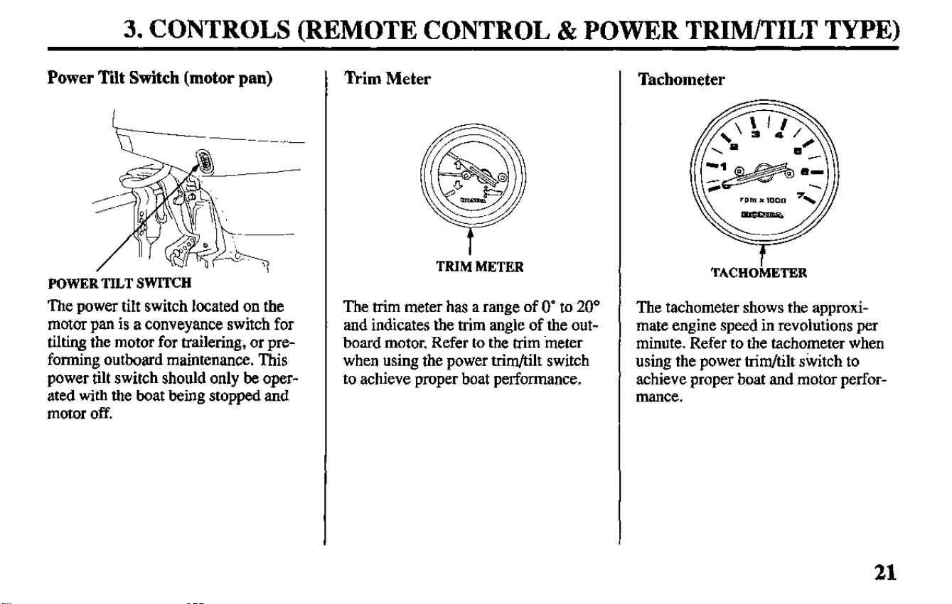
Power Tilt Switch (motor pan)
POWER TILT SWITCH
The power tilt switch located on the
motor pan is a conveyance switch for
tilting the motor for trailering, or pre-
forming outboard maintenance. This
power tilt switch should only be oper-
ated with the boat being stopped and
motor off.
Trim Meter
TRIM METER
The trim meter has a range of 0’ to 20”
and indicates the trim angle of the out-
board motor. Refer to the trim ‘meter
when using the power trim/tilt switch
to achieve proper boat performance.
Tachometer
t
TACHOMETER
The tachometer shows the approxi-
mate engine speed in revolutions per
minute. Refer to the tachometer when
using the power trim/tilt switch to
achieve proper boat and motor perfor-
mance.
21
3. CONTROLS (REMOTE CONTROL & POWER TRIM/TILT TYPE)
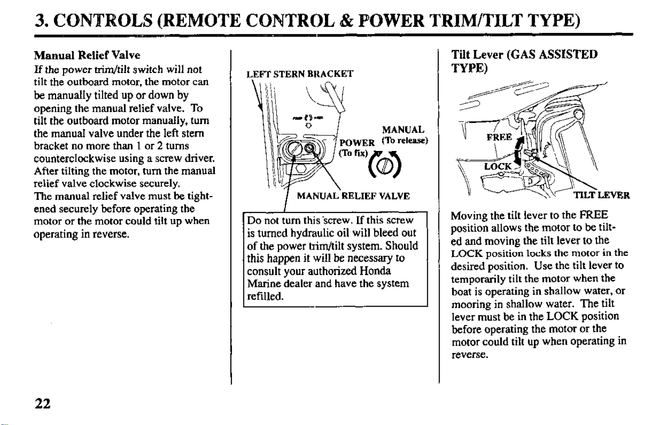
Manual Relief Valve
If the power trim/tilt switch will not
tilt the outboard motor, the motor can
be manually tilted up or down by
opening the manual relief valve. To
tilt the outboard motor manually, turn
the manual valve under the left stem
bracket no more than 1 or 2 turns
counterclockwise using a screw driver.
After tilting the motor, turn the manual
relief valve clockwise securely.
The manual relief valve must be tight-
ened securely before operating the
motor or the motor could tilt up when
operating in reverse.
LEFT STERN BRACKET
MANUAL
WER (To WI-)
Rx)
MANUAL-RELIEF VALVE
Do not turn this -screw. If this screw
is turned hydraulic oil will bleed out
of the power trim/tilt system. Should
this happen it will be necessary to
consult your authorized Honda
Marine dealer and have the system
refilled.
Tilt Lever (GAS ASSISTED
TYPE)
Moving the tilt lever to the FREE
position allows the motor to be tilt-
ed and moving the tilt lever to the
LOCK
position
locks the
motor in the
desired position.
Use
the tilt
lever to
temporarily tilt the motor when the
boat is operating in shallow water, or
mooring in shallow water. The tilt
lever must be in the LOCK position
before operating the motor or the
motor could tilt up when operating in
reverse.
22
3. CONTROLS & INSTRUMENTS (common)
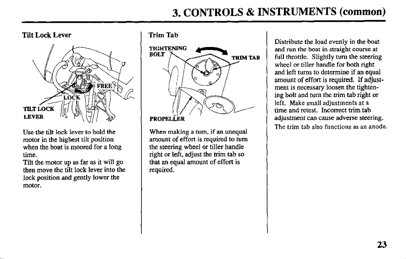
Tilt Lock Lever
Use the tilt lock lever to hold the
motor in the highest tilt position
when the boat is moored for a long
time.
Tilt the motor up as far as it will go
then move the tilt lock lever into the
lock position and gently lower the
motor.
Trim Tab
PROPELLER
When making a turn, if an unequal
amount of effort is required to turn
the steering wheel or tiller handle
right or left, adjust the trim tab so
that an equal amount of effort is
required.
TAB
I
Distribute the load evenly in the boat
and run the boat in straight course at
full throttle. Slightly turn the steering
wheel or tiller handle for both right
and left turns to determine if an equal
amount of effort is required. If adjust-
ment is necessary loosen the tighten-
ing bolt and turn the trim tab right or
left. Make small adjustments at a
time and retest. Incorrect trim tab
adjustment can cause adverse steering.
The trim tab also functions as an anode.
23
3. CONTROLS d!k INSTRUMENTS (common)
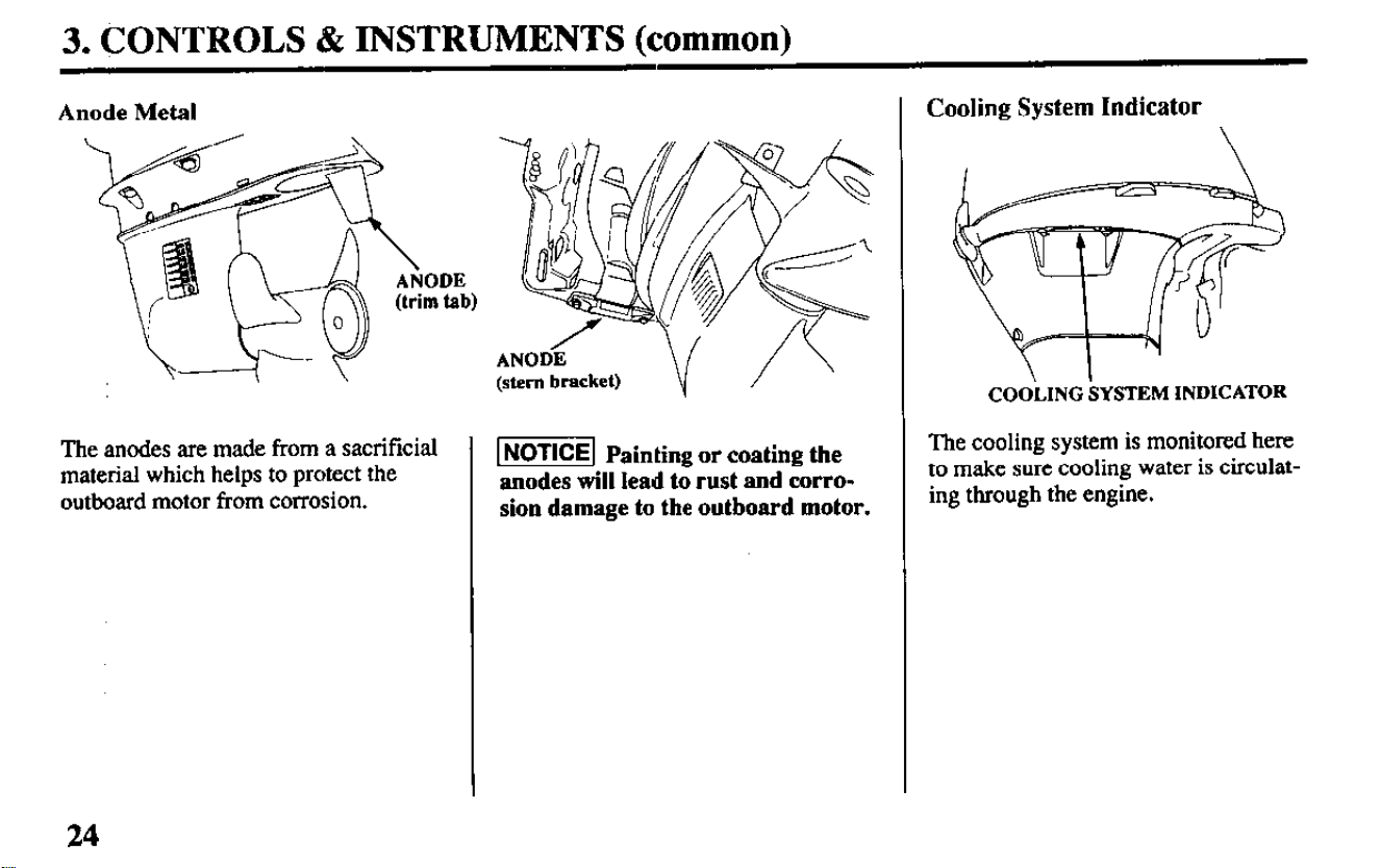
Anode Metal
Y----l
\
The anodes are made from a sacrificial
material which helps to protect the
outboard motor from corrosion.
ANODiX
(stem
bracket)
1
NOTICE]
Painting or coating the
anodes will lead to rust and corro-
sion damage to the outboard motor.
Cooling System Indicator
C~~'LIN~ SYSTEM
INDICATOR
The cooling system is monitored here
to make sure cooling water is circulat-
ing through the engine.
24
3. CONTROLS & INSTRUMENTS (common)
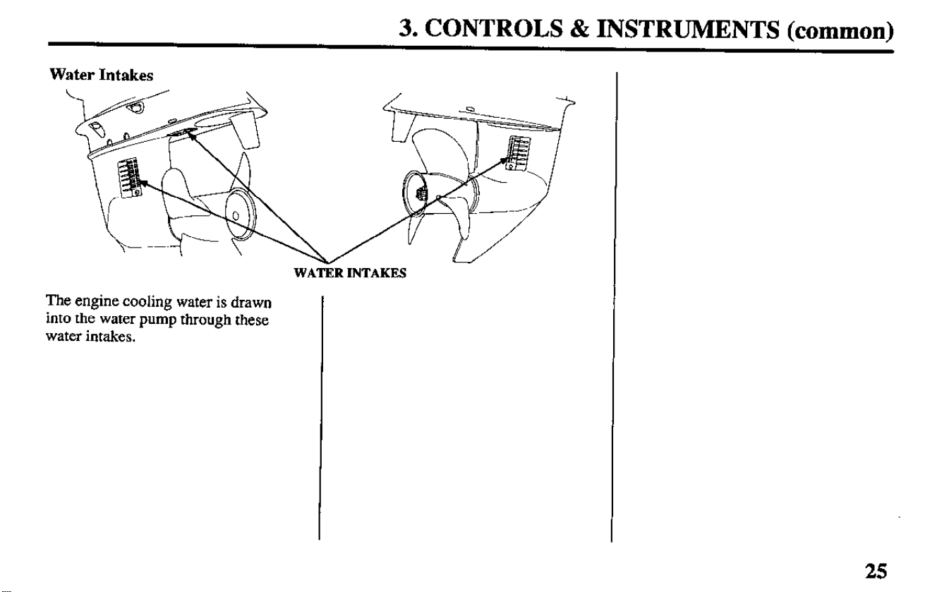
Water Intakes
WATER INTAKES
The engine cooling water is drawn
into the water pump through these
water intakes.
25
3. CONTROLS & INSTRUMENTS (common)
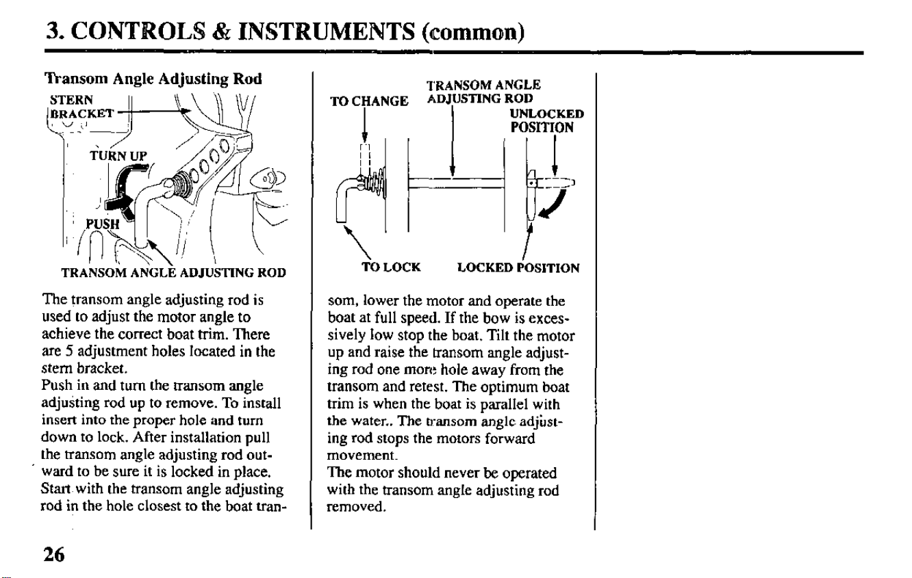
Transom Angle Adjusting Rod
TRANSOM ANGLE ADJUSTING ROD
The transom angle adjusting rod is
used to adjust the motor angle to
achieve the correct boat trim. There
are 5 adjustment holes located in the
stem bracket.
Push in and turn the transom angle
adjusting rod up to remove. To install
insert into the proper hole and turn
down to lock. After installation pull
the transom angle adjusting rod out-
. ward to be sure it is locked in place.
Start with the transom angle adjusting
rod in the hole closest to the boat tran-
26
TRANSOM ANGLE
ADJUSTING ROD
UNLOCKED
POSITION
‘ItI LOCK
LOCKED POSITION
som, lower the motor and operate the
boat at full speed. If the bow is exces-
sively low stop the boat. Tilt the motor
up and raise the transom angle adjust-
ing rod one more hole away from the
transom and retest. The optimum boat
trim is when the boat is parallel with
the water.. The transom angle adjust-
ing rod stops the motors forward
movement.
The motor should never be operated
with the transom angle adjusting rod
removed.
3. CONTROLS & INSTRUMENTS (common)
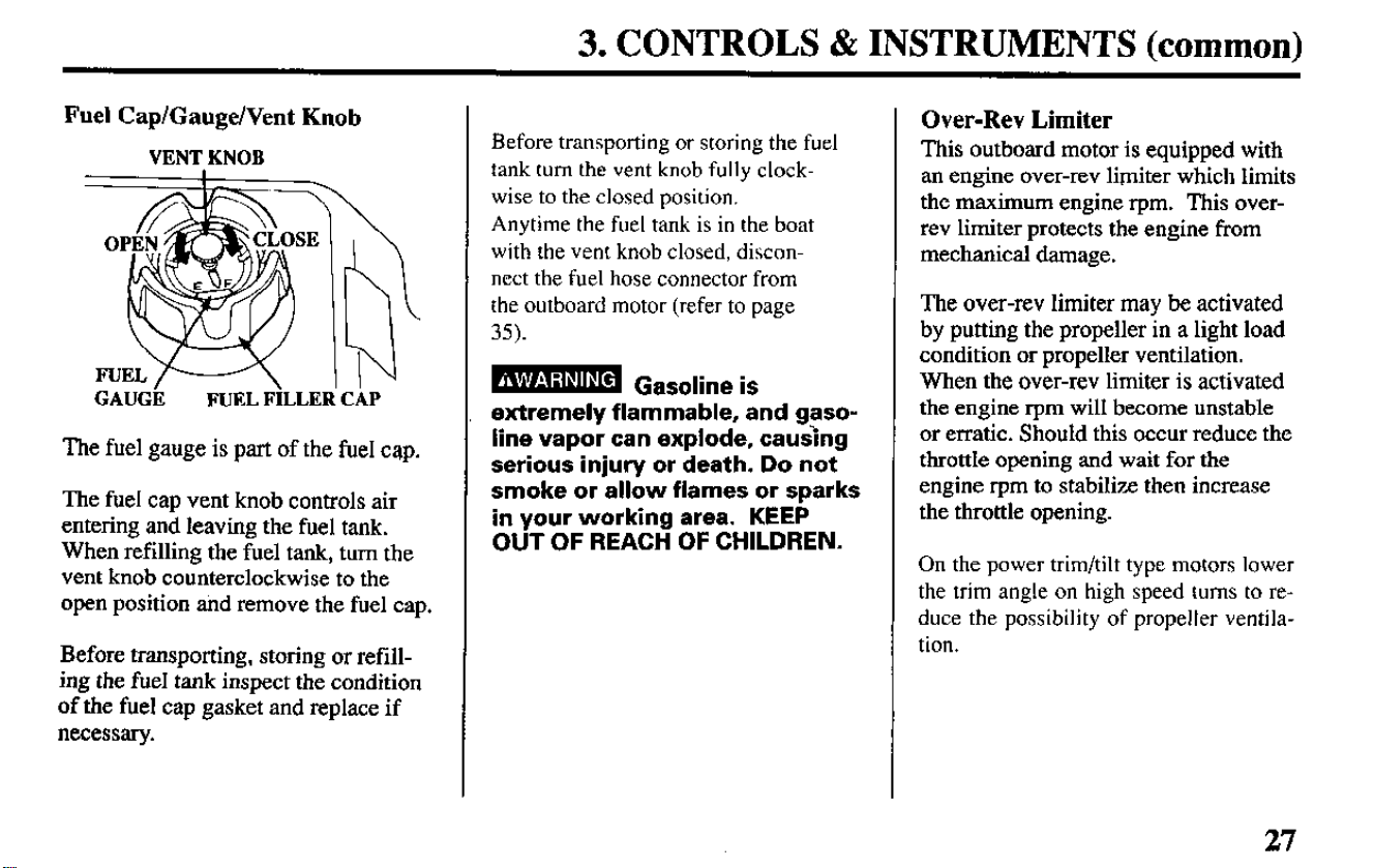
Fuel Cap/Gauge/Vent Knob
VENT KNOB
GAUGk FUEL FiLLEIi CkP
The fuel gauge is part of the fuel cap.
The fuel cap vent knob controls air
entering and leaving the fuel tank.
When refilling the fuel tank, turn the
vent knob counterclockwise to the
open position and remove the fuel cap.
Before transporting, storing or refill-
ing the fuel tank inspect the condition
of the fuel cap gasket and replace if
necessary.
Before transporting or storing the fuel
tank turn the vent knob fully clock-
wise to the closed position.
Anytime the fuel tank is in the boat
with the vent knob closed, discon-
nect the fuel hose connector from
the outboard motor (refer to page
35).
extremely flammable, and gaso-
line vapor can explode, causing
serious injury or death. Do not
smoke or allow flames or sparks
in your working area. KEEP
OUT OF REACH OF CHILDREN.
Over-Rev Limiter
This outboard motor is equipped with
an engine over-rev limiter which limits
the maximum engine rpm. This over-
rev limiter protects the engine from
mechanical damage.
The over-rev limiter may be activated
by putting the propeller in a light load
condition or propeller ventilation.
When the over-rev limiter is activated
the engine rpm will become unstable
or erratic. Should this occur reduce the
throttle opening and wait for the
engine r-pm to stabilize then increase
the throttle opening.
On the power trim/tilt type motors lower
the trim angle on high speed turns to re-
duce the possibility of propeller ventila-
tion.
27
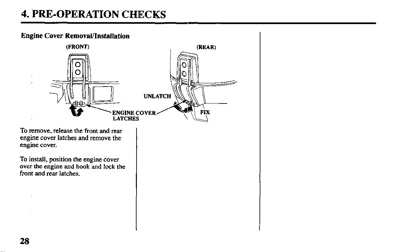
Engine Cover Removal/InstalIation
(FRONT) (WAR)
ENGINE COVER
LATCHES
To remove, release the front and rear
engine cover latches and remove the
engine cover.
To install, position the engine cover
ovei the engine and hook and lpck the
front and rear latches.
28
4. PRE-OPERATION CHECKS
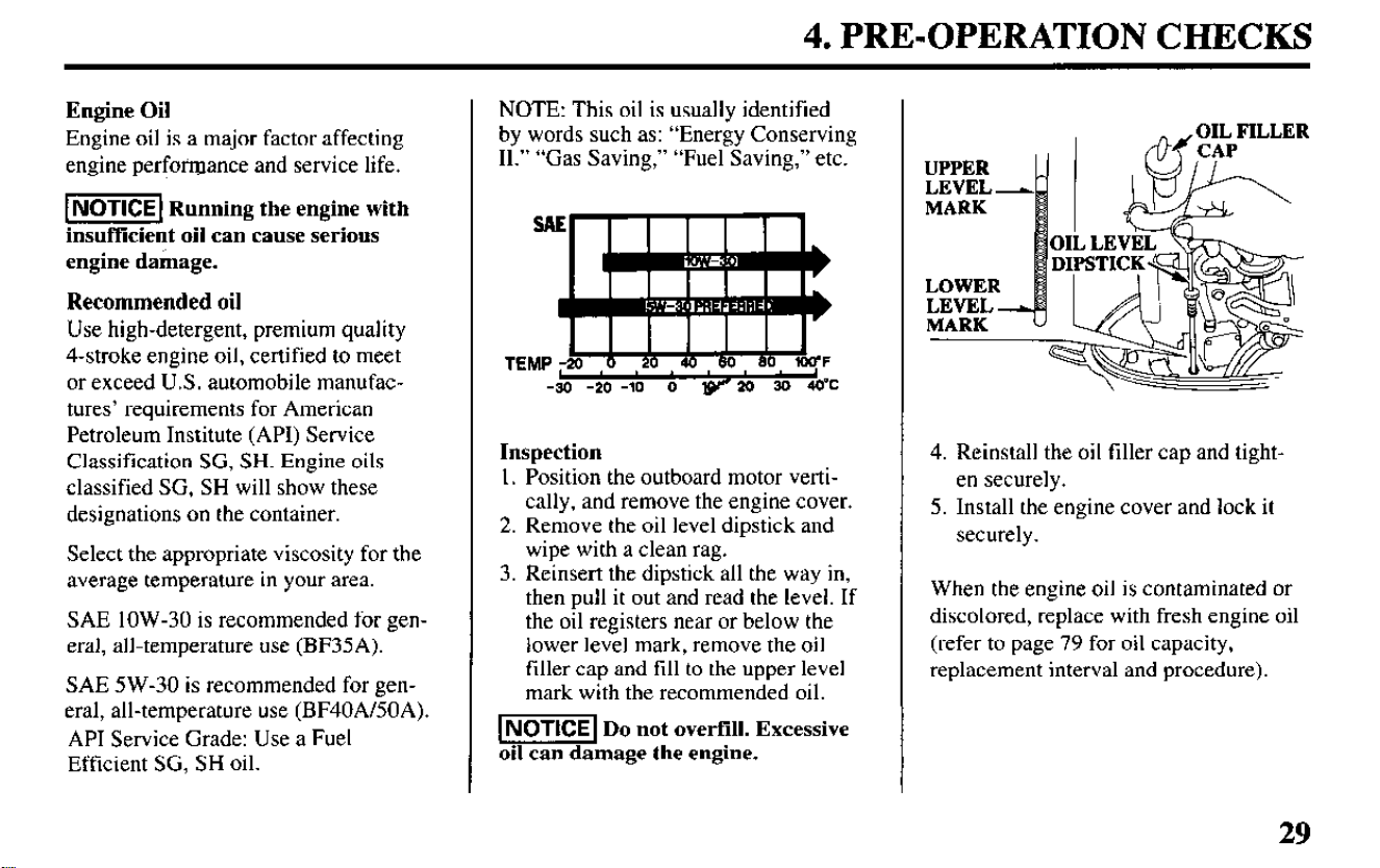
Engine Oil
Engine oil is a major factor affecting
engine performance and service life.
-1 Running the engine with
insufficient oil can cause serious
engine damage.
Recommended oil
Use high-detergent, premium quality
4-stroke engine oil, certified to meet
or exceed U.S. automobile manufac-
tures’ requirements for American
Petroleum Institute (API) Service
Classification SG, SH. Engine oils
classified SG, SH will show these
designations on the container.
Select the appropriate viscosity for the
average temperature in your area.
SAE low-30 is recommended for gen-
eral, all-temperature use (BF35A).
SAE 5 W-30 is recommended for gen-
eral, all-temperature use (BF40A/SOA).
API Service Grade: Use a Fuel
Efficient SG, SH oil.
NOTE: This oil is usually identified
by words such as: “Energy Conserving
II.” “Gas Saving, ” “Fuel Saving,” etc.
Inspection
1. Position the outboard motor verti-
cally, and remove the engine cover.
2. Remove the oil level dipstick and
wipe with a clean rag.
3. Reinsert the dipstick all the way in,
then pull it out and read the level. If
the oil registers near or below the
lower level mark, remove the oil
filler cap and fill to the upper level
mark with the recommended oil.
NOTICE Do not overfill. Excessive
oil can damage the engine.
4. Reinstall the oil tiller cap and tight-
en securely.
5. Install the engine cover and lock it
securely.
When the engine oil is contaminated or
discolored, replace with fresh engine oil
(refer to page 79 for oil capacity,
replacement interval and procedure).
29
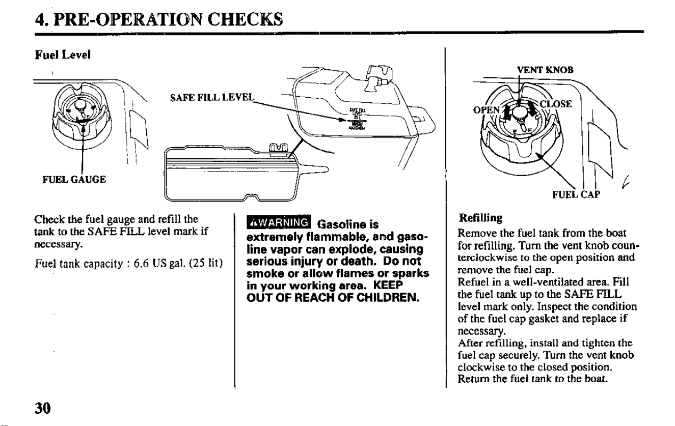
4. PRE-OE’ERATION CHECKS
Fuel Level
I
FUELGhGE
Check the fuel gauge and refill the
tank to the SAFE FILL level mark if
necessary.
Fuel tank capacity : 6.6 US gal. (25 lit)
30
B Gasoline is
extremely flammable, arnd gaso-
line vapor can explode, causing
serious injury or death. Do not
smoke or allow flames or sparks
in your working area. KEEP
OUT OF REACH OF CHILDREN.
VENTKNOB
FUELCAP
Refilling
Remove the fuel tank from the boat
for refilling. Turn the vent knob coun-
terclockwise to the open position and
remove the fuel cap.
Refuel in a well-ventilated area. Fill
the fuel tank up to the SAFE FILL
level mark only. Inspect the condition
of the fuel cap gasket and replace if
necessary.
After refilling, install and tighten the
fuel cap securely. Turn the vent knob
clockwise to the closed position.
Return the fuel tank to the boat.
4. PRE-OPERATION CHECKS
Fuel Recommendations
Use unleaded gasoline with a pump octane rating of 86
or higher.
This engine is designed to operate on unleaded gasoline.
Unleaded gasoline produces fewer engine and spark plug
deposits and extends exhaust system life.
Never use stale or contaminated gasoline or an oil/gaso-
line mixture. Avoid getting dirt or water in the fuel tank.
Occasionally you may hear light “spark knock” or “ping-
ing” (metallic rapping noise) while operating under heavy
loads. This is no cause for concern.
If spark knock or pinging occurs at a steady engine speed,
under normal load, change brands of gasoline. If spark
knock or pinging persists, see an authorized Honda Ma-
rine or Honda Outboard Motor dealer.
1-1 Running the engine with persistent spark
knock or pinging can cause engine damage.
Running the engine with persistent spark knock or ping-
ing is misuse, and the Distributor’s Limited Warranty
does not cover parts damaged by misuse.
31
4. PRE-OPERATION CHECKS
Oxygenated Fuels
Some conventional gasolines are being blended with alco-
hol or an ether compound. These gasolines are collec-
tively referred to as oxygenated fuels. To meet clean air
standards, some areas of the United States and Canada
use oxygenated fuels to help reduce emissions.
If you use an oxygenated fuel, be sure it is unleaded and
meets the minimum octane rating requirement.
Before using an oxygenated fuel, try to confirm the fuel’s
contents. Some states/provinces require this information
to be posted on the pump.
The following are the EPA approved percentages of oxy-
genates:
ETHANOL -
(ethyl or grain alcohol) 10% by volume
You may use gasoline containing up to
10% ethanol by volume. Gasoline con-
taining ethanol may be marketed under
the name “Gasohol”.
MTBE - (Methyl Tertiary Butyl Ether) 15% by volume
You may use gasoline containing up to
15% MTBE by volume.
32
METHANOL
-(methyl or wood alcohol) 5% by volume
You may use gasoline containing up to
5% methanol by volume, as long as it
also contains cosolvents and corrosion
inhibitors to protect the fuel system.
Gasoline containing more than 5%
methanol by volume may cause starting
and/or performance problems. It may
also damage metal, rubber, and plastic
parts of your fuel system.
If you notice any undesirable operating symptoms, try an-
other service station, or switch to another brand of gaso-
line.
Fuel system damage or performance problems resulting
from the use of an oxygenated fuel containing more than
the percentages of oxygenates mentioned above are not
covered under warranty.
4. PRE-OPERATION CHECKS
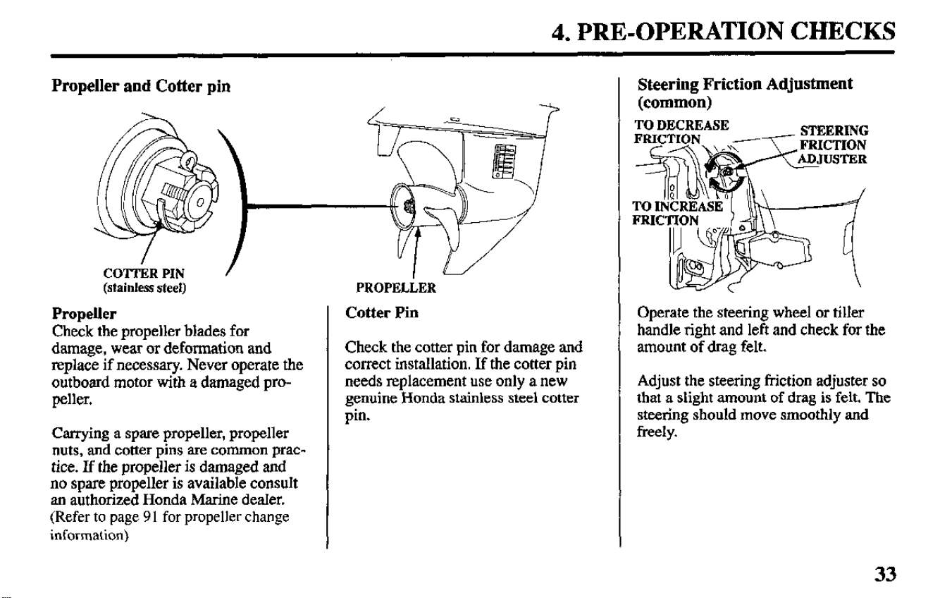
Propeller and Cotter pin
COTTERPIN /
(stainless steel)
Propeller
Check the propeller blades for
damage, wear or deformation and
replace if necessary. Never operate the
outboard motor with a damaged pro-
peller.
Carrying a spare propeller, propeller
nuts, and cotter pins are common prac-
tice. If the propeller is damaged and
no spare propeller is available consult
an authorized Honda Marine dealer.
(Refer to page 91 for propeller change
information)
PROPELLER
Cotter Pin
Check the cotter pin for damage and
correct installation. If the cotter pin
needs replacement use only a new
genuine Honda stainless steel cotter
pin.
Steering Friction Adjustment
(common)
TO DECREASE
STEERING
\ e\,< FRICTION
Operate the steering wheel or tiller
handle right and left and check for the
amount of drag felt.
Adjust the steering friction adjuster so
that a slight amount of drag is felt. The
steering should move smoothly and
freely.
33
4. PRE-OPERATION CHECKS
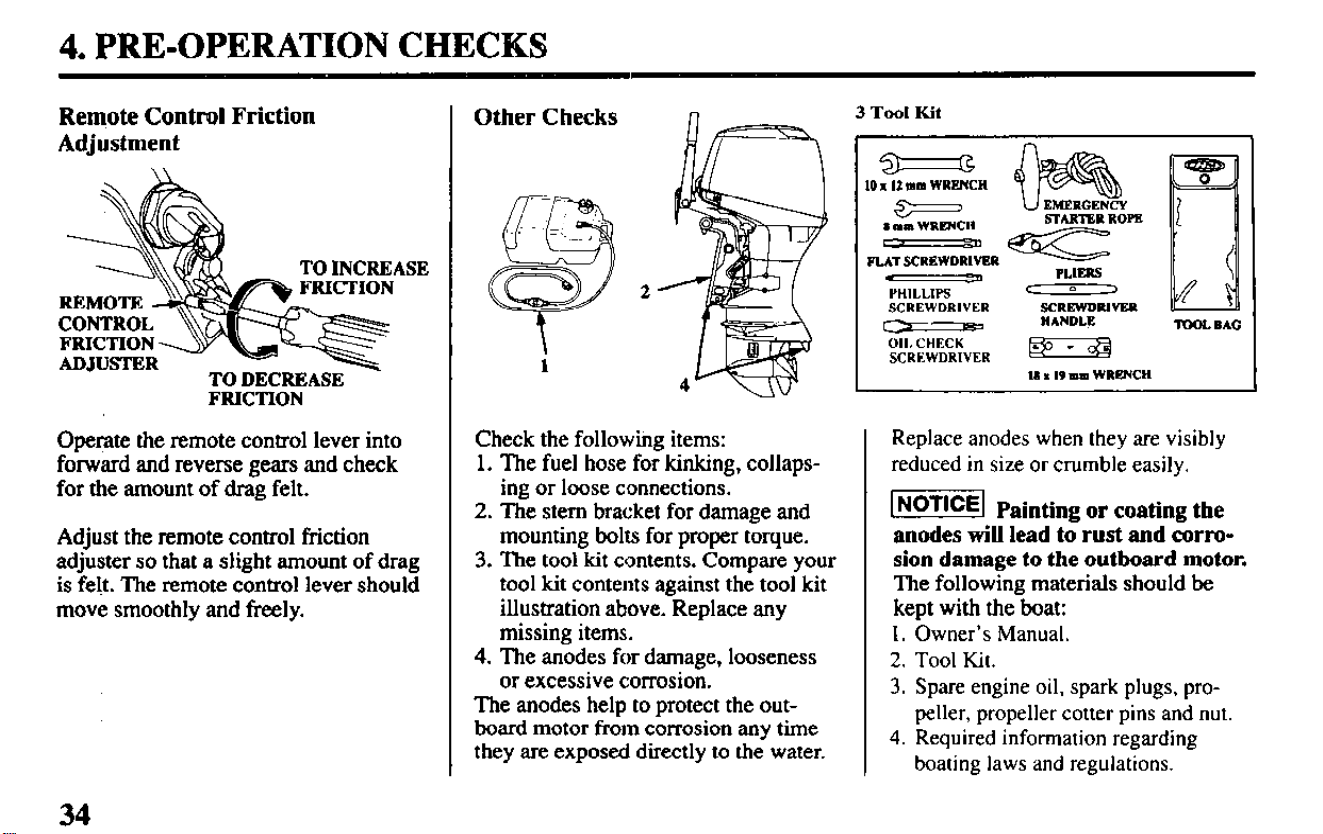
Remote Contml Friction
Adjustment
TO INCREASE
-
FRICTION
Operate the remote control lever into
forward and reverse gears and check
for the amount of drag felt.
Adjust the remote control friction
adjuster so that a slight amount of drag
is felt. The remote control lever should
move smoothly and freely.
2
Check the followihg items:
1. The fuel hose for kinking, collaps-
ing or loose connections.
2. The stem bracket for damage and
mounting bolts for proper torque.
3. The tool kit contents. Compare your
tool kit contents against the tool kit
illustration above. Replace any
missing items.
4.
The anodes for damage, looseness
or excessive corrosion.
The anodes help to protect the out-
board motor from corrosion any time
they are exposed directly to the water.
Other Checks
PUT SCREWDRIVER
I II
PLIRRS
YHILLIPS
‘ 0 -)
SCREWDRIVER SCRRWDRIVRR
c2
HANDLE
nmL BAG
011. CHECK
SCREWDRIVER
#”
II I I9 mm WRENCH
Replace anodes when they are visibly
reduced in size or crumble easily.
w Painting or coating the
anodes will lead to rust and corro-
sion damage to the outboard motor.
The following materials should be
kept with the boat:
1. Owner’s Manual.
2.
Tool Kit.
3. Spare engine oil, spark plugs, pro-
peller, propeller cotter pins and nut.
4. Required information regarding
boating laws and regulations.
34
5. STARTING THE ENGINE
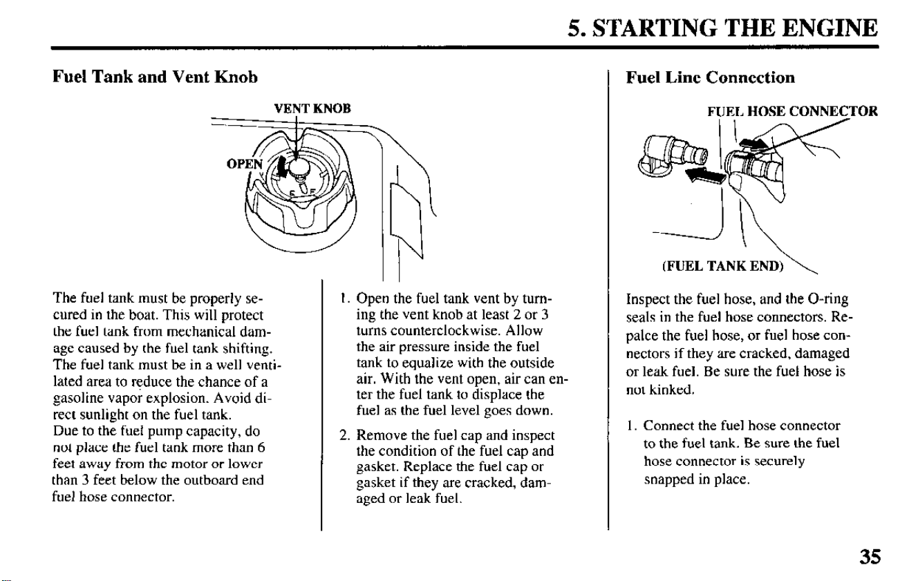
Fuel Tank and Vent Knob
VENT KNOB
The fuel tank must be properly se-
cured in the boat. This will protect
the fuel tank from mechanical dam-
age caused by the fuel tank shifting.
The fuel tank must be in a well venti-
lated area to reduce the chance of a
gasoline vapo; explosion. Avoid di-
rect sunlight on the fuel tank.
Due to the fuel pump capacity, do
not place the fuel tank more than 6
feet away from the motor or lower
than 3 feet below the outboard end
fuel hose connector.
1. Open the fuel tank vent by turn-
ing the vent knob at least 2 or 3
turns counterclockwise. Allow
the air pressure inside the fuel
tank to equalize with the outside
air. With the vent open, air can en-
ter the fuel tank to displace the
fuel as the fuel level goes down.
2. Remove the fuel cap and inspect
the condition of the fuel cap and
gasket. Replace the fuel cap or
gasket if they are cracked,
dam-
aged or leak fuel.
Fuel Line Connection
FUEL HOSE CONNECTOR
(FUEL TANK END)\
Inspect the fuel hose, and the O-ring
seals in the fuel hose connectors. Re-
palce the fuel hose, or fuel hose con-
nectors if they are cracked, damaged
or leak fuel. Be sure the fuel hose is
not kinked.
1. Connect the fuel hose connector
to the fuel tank. Be sure the fuel
hose connector is securely
snapped in place.
35
5. STARTING THE ENGINE
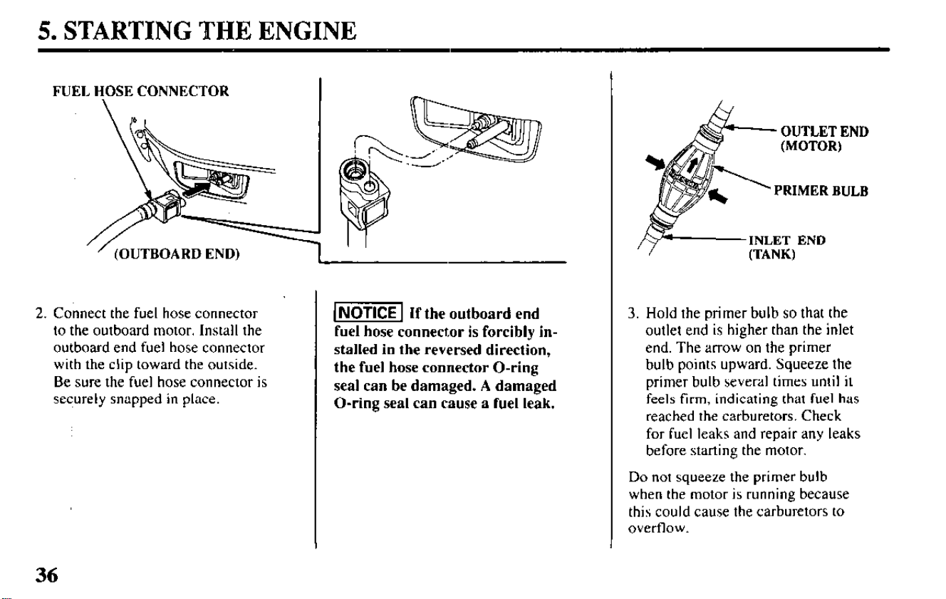
FUEL HOSE CONNECTOR
(OUTBOARD END)
2. Connect the fuel hose connector
to the outboard motor. Install the
outboard end fuel hose connector
with the clip toward the outside.
Be sure the fuel hose connector is
securely snapped in place.
1 NOTICE 1 If the outboard end
fuel hose connector is forcibly in-
stalled in the reversed direction,
the fuel hose connector O-ring
seal can be damaged. A damaged
O-ring seal can cause a fuel leak.
OUTLET END
PRIMER BULB
3. Hold the primer bulb so that the
outlet end is higher than the inlet
end. The arrow on the primer
bulb points upward. Squeeze the
primer bulb several times until it
feels firm, indicating that fuel has
reached the carburetors. Check
for fuel leaks and repair any leaks
before starting the motor.
Do not squeeze the primer bulb
when the motor is running because
this could cause the carburetors to
overflow.
36
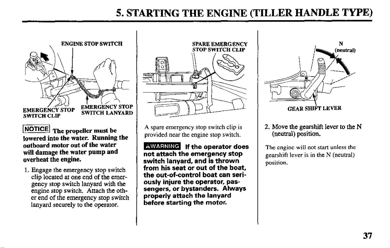
5. STARTING THE ENGINE (TILLER HANDLE TYPE)
ENGINE STOP SWITCH
SWITCH CLIP
piim%j
The nroneller must be
lowered into thi wker. Running the
outboard motor out of the water
will damage the water pump and
overheat the engine.
1. Engage the emergency stop switch
clip located at one end of the emer-
gency stop switch lanyard with the
engine stop switch. Attach the oth-
er end of the emergency stop switch
lanyard securely to the operator.
SPARE EMERGENCY
STOP SWITCH CLIP
A spare emergency stop switch clip is
provided near the engine stop switch.
B If the operator does
not attach the emergency stop
switch lanyard, and is thrown
from his seat or out of the boat,
the out-of-control boat can seri-
ously injure the operator, pas-
sengers, or bystanders. Always
properly attach the lanyard
before starting the motor.
GEAR SHIFF LEVER
2. Move the gearshift lever to the N
(neutral) position.
The engine will not start unless the
gearshift lever is in the N (neutral)
position.
37
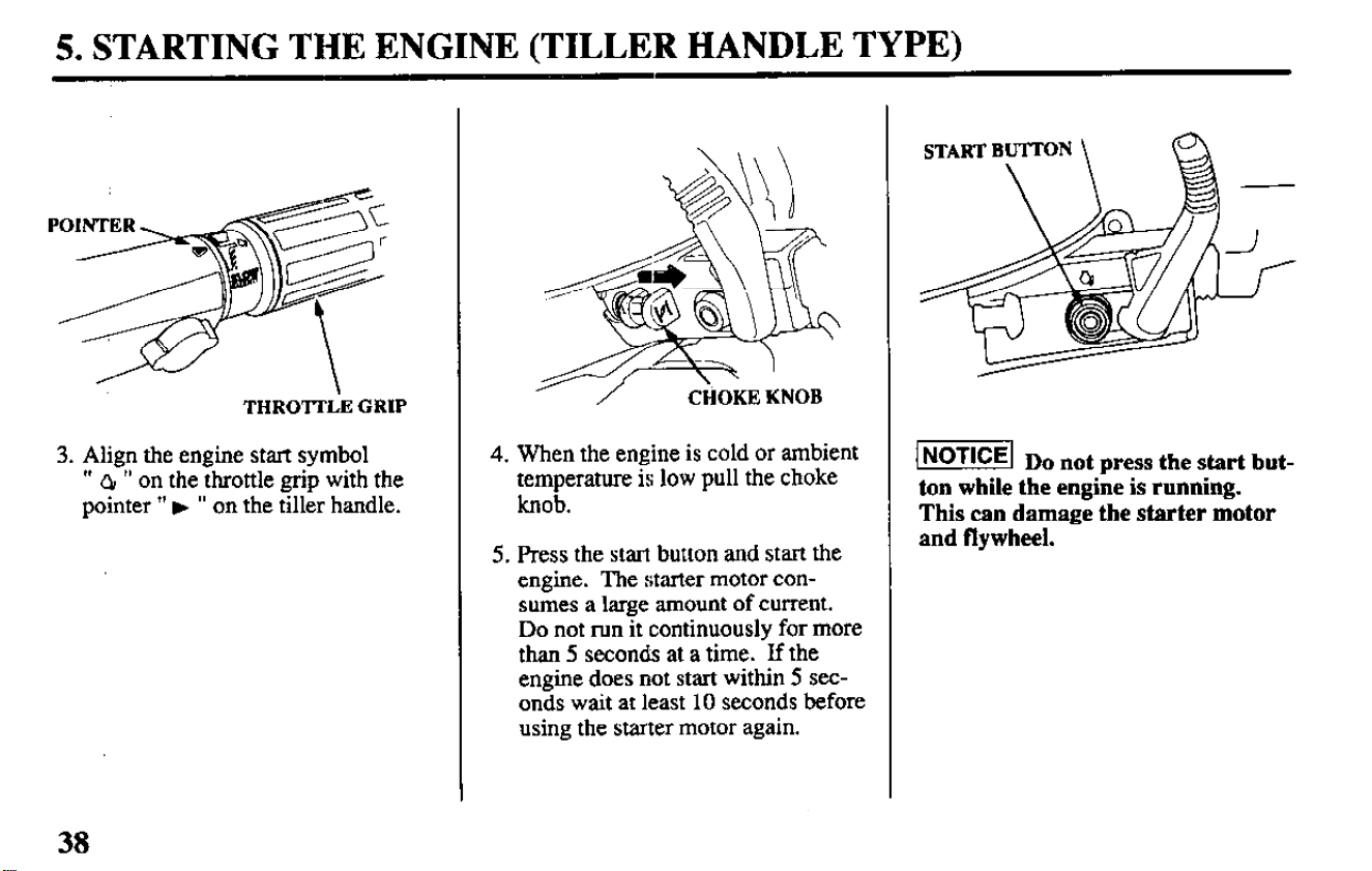
5. STARTING THE ENGINE (TILLER HANDLE TYPE)
THROlTIiE GRIP
3. Align the engine start symbol
” Q, ” on the throttle grip with the
pointer ” w ” on the tiller handle.
’ /
CHOKE KNOB
4. When the engine is cold or ambient
temperature is low pull the choke
knob.
5. Press the start button and start the
engine. The starter motor con-
sumes a large amount of current.
Do not run it continuously for more
than 5 seconds at a time. If the
engine does not start within 5 sec-
onds wait at least 10 seconds before
using the starter motor again.
k!f@ Do not press the start but-
ton while the engine is running.
This can damage the starter motor
and flywheel.
38
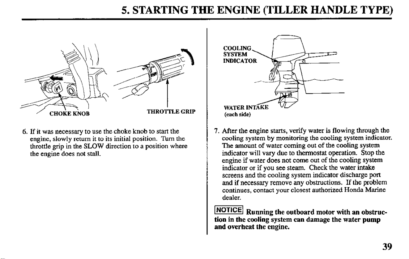
5. STARTING THE ENGINE (TILLER HANDLE TYPE)
CHO;E K\NO;
THROTTLE GRIP
6. If it was necessary to use the choke knob to start the
engine, slowly return it to its initial position. Turn the
throttle grip in the SLOW direction to a position where
the engine does not stall.
-ATT---
WATER INTAKE
(each side)
7. After the engine starts, verify water is flowing through the
cooling system by monitoring the cooling system indicator.
The amount of water coming out of the cooling system
indicator will vary due to thermostat operation. Stop the
engine if water does not come out of the cooling system
indicator or if you see steam. Check the water intake
screens and the cooling system indicator discharge port
and if necessary remove any obstructions. If the problem
continues, contact your closest authorized Honda Marine
dealer.
-1 Ru
nning the outboard motor with an obstruc-
tion in the cooling system can damage the water pump
and overheat the engine.
39
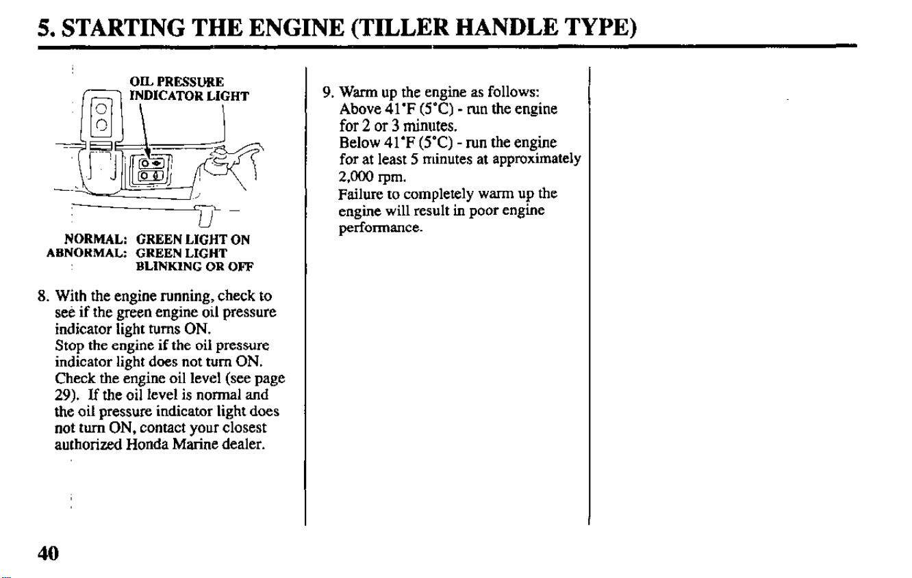
5. STARTING THE ENGINE (TILLER HANDLE TYPE)
OIL PRESSURE
NORMAL: GREEN LIGHT ON
ABNORMAL: GREEN LIGHT
BLINKING OR OFF
8. With the engine running, check to
see if the green engine oil pressure
indicator light turns ON.
Stop the engine if the oil pressure
indicator light does not turn ON.
Check the engine oil level (see page
29). If the oil level is normal and
the oil pressure indicator light does
not turn ON, contact your closest
authorized Honda Marine dealer.
9. Warm up the engine as follows:
Above 41’F (YC) - run the engine
for 2 or 3 minutes.
Below 41’F (5°C) - run the engine
for at least 5 minutes at approximately
2,000 rpm.
Failure to completely warm up the
engine will result in poor engine
performance.
40
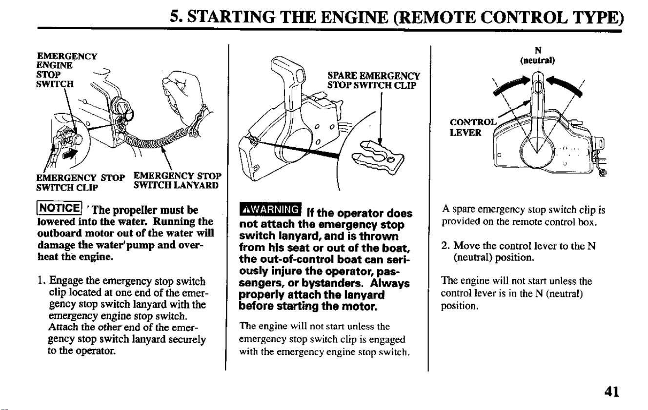
5. STARTING THE ENGINE (REMOTE CONTROL TYPE)
EMERGENCY
EkERGENCY STOP EMERGENCY STOP
SWITCH CLIP
SWITCH LANYARD
1 NoTlq ’ The propeller must be
lowered into the water. Running the
outboard motor out of the water will
damage the water’pump and over-
heat the engine.
1. Engage the emergency stop switch
clip located at one end of the emer-
gency stop switch lanyard with the
emergency engine stop switch.
Attach the other end of the emer-
gency stop switch lanyard securely
to the operator.
SPARE EMERGENCY
STOP SWITCH
CLIP
mmm
If the operator does
not attach the emergency stop
switch lanyard, and is thrown
from his seat or out of the boat,
the out-of-control boat can seri-
ously injure the operator, pas-
sengers, or bystanders. Always
properly attach the lanyard
before starting the motor.
The engine will not start unless the
emergency stop switch clip is engaged
with the emergency engine stop switch.
(nekl)
CONTRO
LEVER
A spare emergency stop switch clip is
provided on the remote control box.
2. Move the control lever to the N
(neutral) position.
The engine will not start unless the
control lever is in the N (neutral)
position.
41
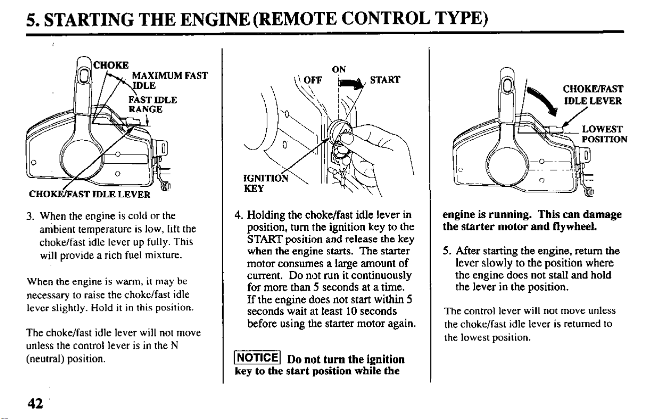
5. STARTING THE ENGINE (REMOTE CONTROL TYPE)
3. When the engine is
cold or the
ambient temperature is low, lift the
choke/fast idle lever up fully. This
will provide a rich fuel mixture.
When the engine is warm, it
may be
necessary to
raise the choke/fast idle
lever slightly. Hold it in this position.
The choke/fast idle lever will not move
unless the control lever is in the N
(neutral) position.
ON
4. Holding the choke/fast idle lever in
position, turn the ignition key to the
START position and release the key
when the engine starts. The starter
motor consumes a large amount of
current. Do not run it continuously
for more than 5 seconds at a time.
If the engine does not start within 5
seconds wait at least 10 seconds
before using the starter motor again.
[m Do not turn the ignition
key to the start position while the
engine is running. This can damage
the starter motor and flywheel.
5. After starting the engine, return the
lever slowly to the position where
the engine does not stall and hold
the lever in the position.
The control lever will not move unless
the choke/fast idle lever is returned
to
the lowest position.
42
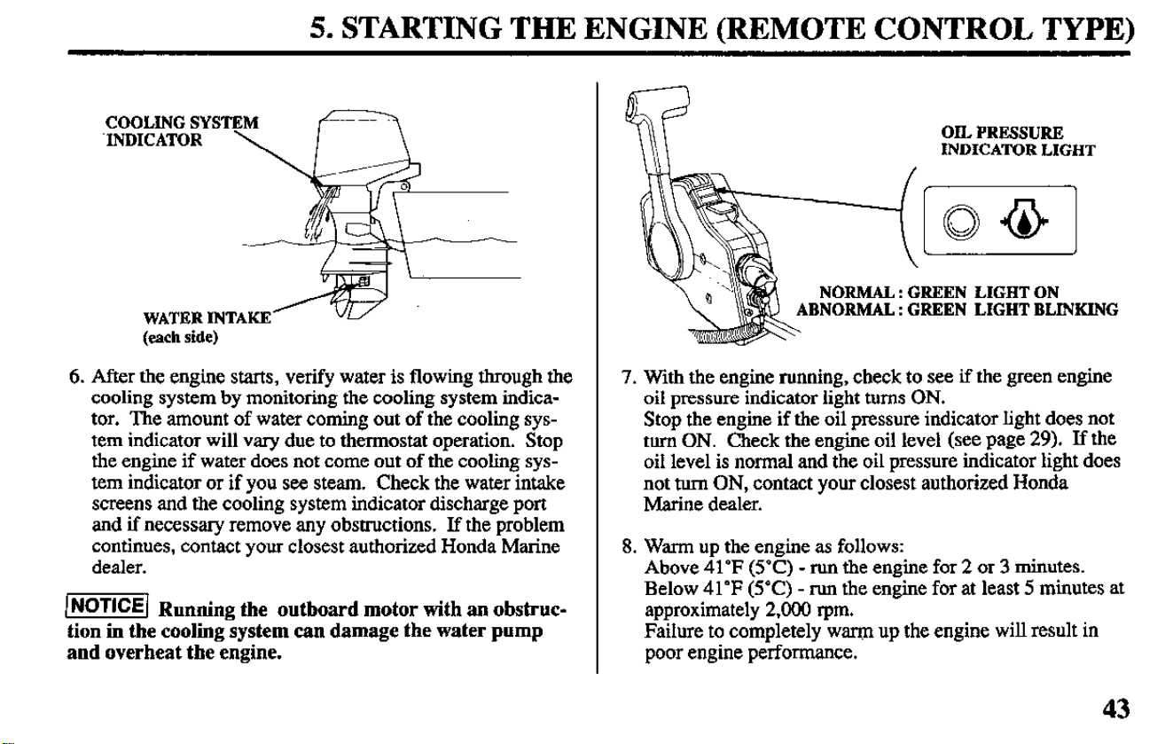
5. STARTING THE ENGINE (REMOTE CONTROL TYPE)
COOLING SYSTEM
X’JDICATOR \
WATER INTAKE
(each side)
6. After the engine starts, verify water is flowing through the
cooling system by monitoring the cooling system indica-
tor. The amount of water coming out of the cooling sys-
tem indicator will vary due to thermostat operation. Stop
the engine if water does not come out of the cooling sys-
tem indicator or if you see steam. Check the water intake
screens and the cooling system indicator discharge port
and if necessary remove any obstructions. If the problem
continues, contact your closest authorized Honda Marine
dealer.
/=I Ru
nning the outboard motor with an obstruc-
tion in the cooling system can damage the water pump
and overheat the engine.
OiL PRESSURE
INDICATOR LIGHT
7. With the engine running, check to see if the green engine
oil pressure indicator light turns ON.
Stop the engine if the oil pressure indicator light does not
turn ON. Check the engine oil level (see page 29). If the
oil level is normal and the oil pressure indicator light does
not turn ON, contact your closest authorized Honda
Marine dealer.
8. Warm up the engine as follows:
Above 41’F (5°C) - run the engine for 2 or 3 minutes.
Below 41°F (5°C) - run the engine for at least 5 minutes at
approximately 2,000 rpm.
Failure to completely warm up the engine will result in
poor engine performance.
43
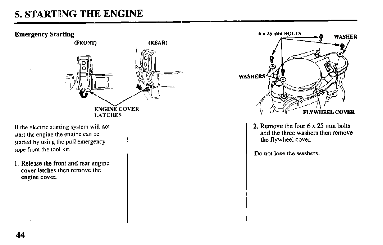
5. STARTING THE ENGINE
Emergency Starting
(FRONT)
(REAR)
ENGINE COVER
LATCHES
If the electric starting system will
not
start the engine the engine can be
started by using the pull
emergency
rope from the tool kit.
1. Release the front and rear engine
cover latches then remove the
engine cover.
2. Remove the four 6 x 25 mm bolts
and the three washers then remove
the flywheel cover.
Do
not lose the washers.
44
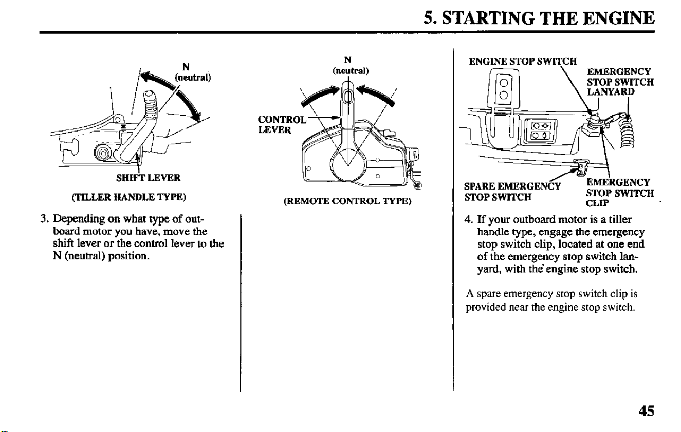
5. STARTING THE ENGINE
SHti LEVER
(TILLER HANDLE TYPE)
3. Depending on what type of out-
board motor you have, move the
shift lever or the control lever to the
N (neutral) position.
N
(neutral)
(REMOTE CONTROL TYPE)
ENGINE STOP SWITCH
-
SPARE EMERGENCC
- EMEkGENCY
STOP SWITCH
STOP SWITCH
CLIP
4. If your outboard motor is a tiller
handle type, engage the emergency
stop switch clip, located at one end
of the emergency stop switch lan-
yard, with the’ engine stop switch.
A spare emergency stop switch clip is
provided near the engine stop switch.
45
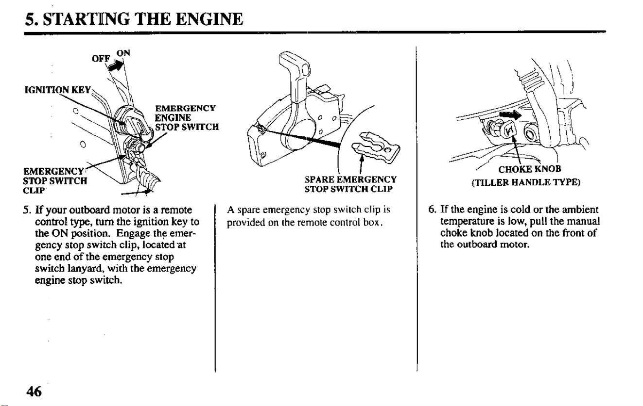
5. STARTltNG THE ENGINE
OFF$
IGNITI
EMERGENCY
STOP SWITCH
CLIP
5. If your outboard motor is a remote
control type, turn the ignition key to
the ON position. Engage the emer-
gency stop switch clip, locatedat
one end of the emergency stop
switch lanyard, with the emergency
engine stop switch.
SPARE EMERGENCY
STOP SWITCH CLIP
A spare emergency stop switch clip is
provided on the remote control box.
/ CHOKEI(NOR
(TILLER HANDLE TYPE)
6. If the engine is cold or the ambient
temperature is low, pull the manual
choke knob located on the front of
the outboard motor.
46
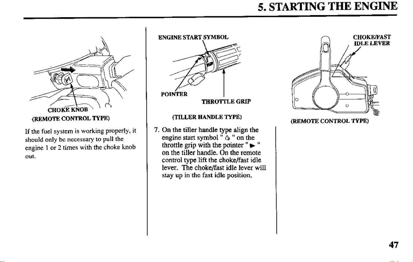
5. STARTING THE ENGINE
(REMOTE CONTROL TYPE)
If the fuel system is working properly, it
should only be necessary to pull the
engine 1 or 2 times with the choke knob
out.
ENGINE START SYMBOL
POIN-TER
I
THROTTLE GRIP
(TILLER HANDLE TYPE)
7. On the tiller handle type align the
engine start symbol ” QI ” on the
throttle grip with the painter ” F ”
on the tiller handle. On the remote
control type.lift the choke/fast idle
lever. The choke/fast idle lever will
stay up in the fast idle position.
n
CHOKE/FAST
(REMOTE CONTROL TYPE)
47
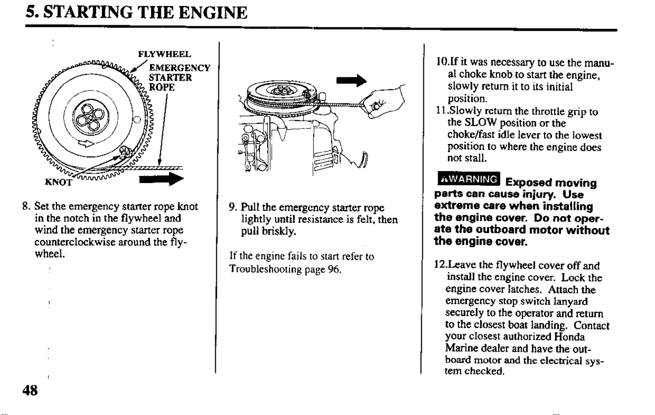
5. STARTING THE ENGINE
OPE
1’
8. Set the emergency starter rope knot
in the notch in the flywheel and
wind the emergency starter rope
counterclockwise around the fly-
wheel.
9. pull the emergency starter rope
lightly until resistance is felt, then
pull briskly.
If the engine fails to start refer to
Troubleshooting page 96.
10X it was necessary to use the manu-
al choke knob to start the engine,
slowly return it to its initial
position.
11 .Slowly return the throttle grip to
the SLOW position or the
choke/fast idle lever to the lowest
position to where the engine does
not stall.
parts can cause-injury.
Use
extreme care when installing
the engine cover. Do not oper-
ate the outboard motor without
the engine cover.
12Leave the flywheel cover off and
install the engine cover. Lock the
engine cover latches. Attach the
emergency stop switch lanyard
securely to the operator and return
to the closest boat landing. Contact
your closest authorized Honda
Marine dealer and have the out-
board motor and the electrical sys-
tem checked.
5. STARTING THE ENGINE
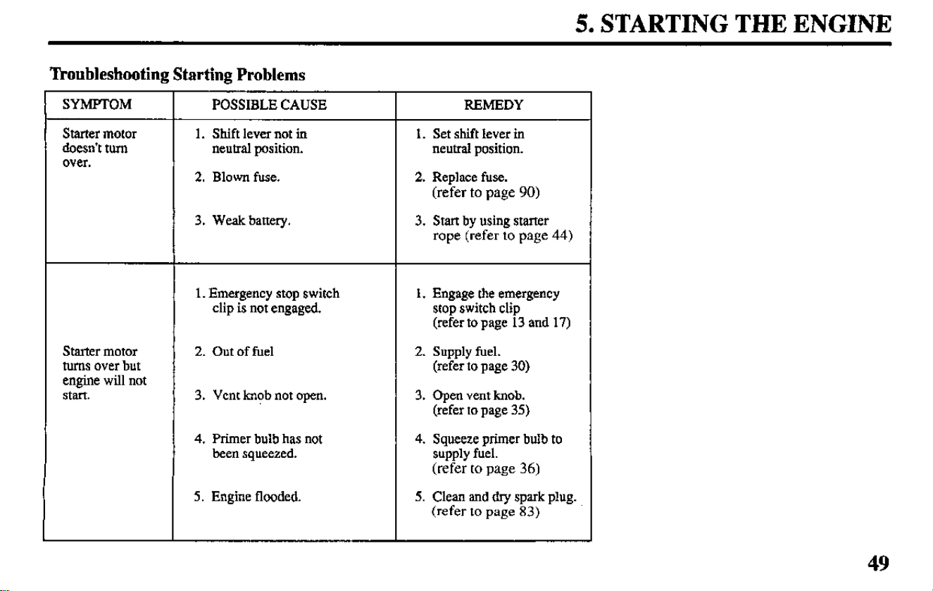
“ikoubleshooting Starting Problems
SYMPTOM
Starter motor
doesn’t mm
over.
POSSIBLE CAUSE
1. Shift lever not in
neutral position.
2. Blown fuse.
REMEDY
1. Set shift lever in
neutral position.
2. Replace fuse.
(refer to page 90)
3. Weak battery. 3. Start by using starter
rope (refer to page 44)
1. Emergency stop switch
clip is not engaged.
1. Engage the emergency
stop switch clip
(refer to page 13 and 17)
Starter motor
turns over but
engine will not
Start.
2. Out of fuel
3. Vent knob not open.
2. Supply fuel.
(refer to page 30)
3. Open vent knob.
(refer to page 35)
4. Primer bulb has not
been squeezed.
4. Squeeze primer bulb to
supply fuel.
(refer to page 36)
5. Engine flooded. 5. Clean and dry spark plug.
(refer to page 83)
49
6. OIE’ERATION
Break-in Procedure
Break-in period 10 hours
Break-in operation allows the moving
parts to wear-in evenly and thus
ensures proper performance and
longer outboard motor life.
Break-in your new outboard motor as
follows:
First 15 minutes:
Run the outboard motor at trolling
speed. Use the minimum amount
of throttle opening necessary to
operate the boat at a safe trolling
speed.
Next 45 minutes:
Run the outboard motor up to a
maximum of 2,000 to 3,000 rpm or
10% to 30% throttle opening.
Next 60 minutes:
Run the outboard motor up to maxi-
mum of 4,000 to 5,000 rpm or 50%
to 80% throttle opening. Short
50
bursts of full throttle are acceptable
but do not operate the motor contin-
uously at full throttle.
Next 8 hours:
Avoid continuous full throttle oper-
ation (100% throttle opening). Do
not run the outboard motor at full
throttle for more than 5 minutes at a
time.
For boats that plane easily, bring the
boat up on plane
then reduce the throttle
opening lo the specified break-in
settings called out above.
6. OPERATION (TILLER HANDLE TYPE)
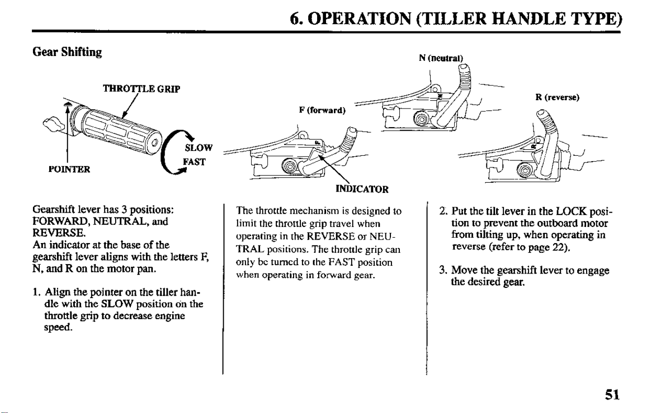
Gear Shifting
N (neutral)
FAST
L
I
POINTER
Gearshift lever has 3 positions:
FORWARD, NEUTRAL, and
REVERSE.
An indicator at the base of the
gearshift lever aligns with the letters F,
N, and R on the motor pan.
1. Align the pointer on the tiller han-
dle with the SLOW position on the
throttle grip to decrease engine
speed.
INiMCATOR
The throttle mechanism is designed to
limit the throttle grip travel when
operating in the
REVERSE
or
NEU-
TRAL
positions. The throttle grip can
only be turned to the
FAST
position
when operating in forward gear.
2. Put the tilt lever in the LOCK posi-
tion to prevent the outboard motor
from tilting up, when operating in
reverse (refer to page 22).
3. Move the gearshift lever to engage
the desired gear.
6. OPERATION (TILLER HANDLE TYPE)
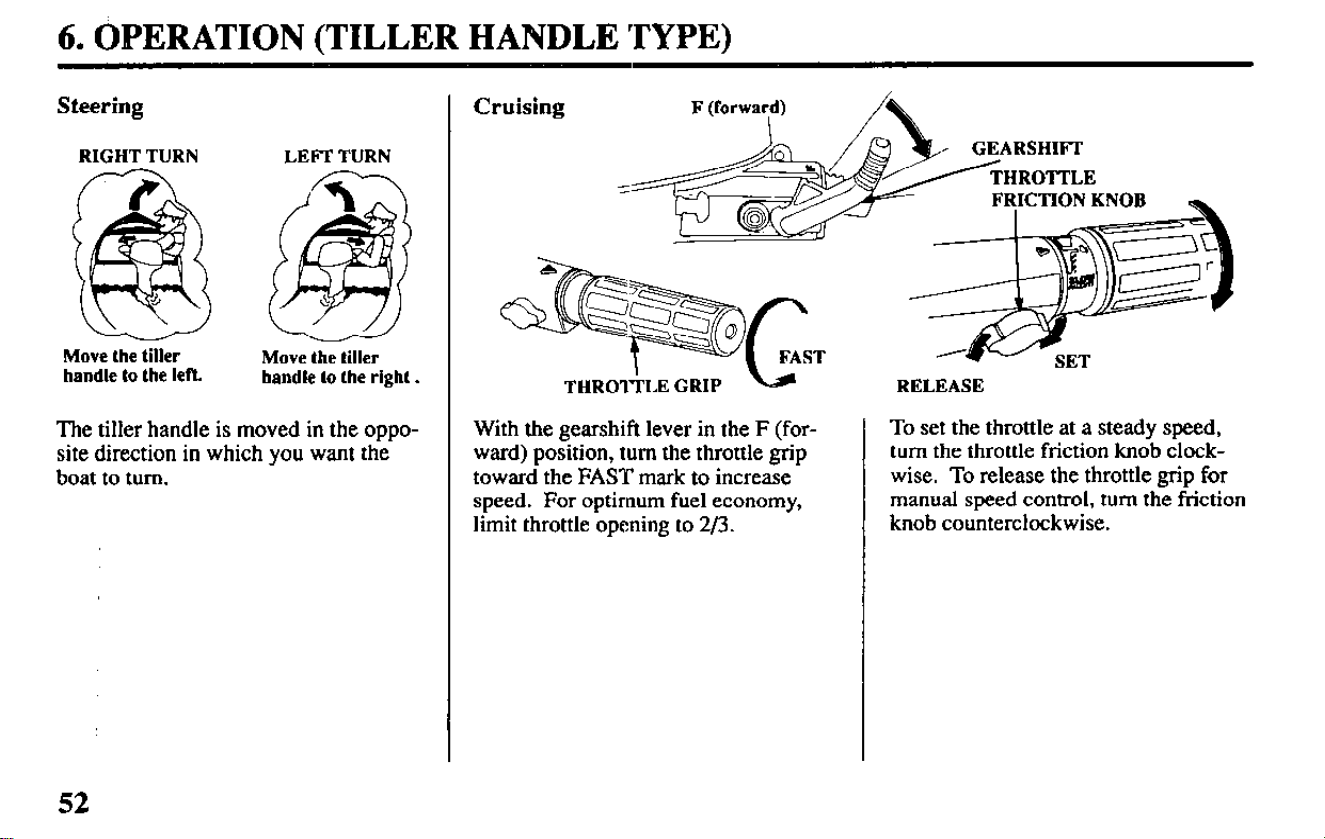
Steering
RIGHT TURN
Move
the tiller
handle to the left.
LEFT TURN
Move the tiller
handle to the right.
The tiller handle is moved in the oppo-
site direction in which you want the
boat to turn.
Cruising
THRO&LE GRIP b
With the gearshift lever in the F (for-
ward) position, turn the throttle grip
toward the FAST mark to increase
speed. For optimum fuel economy,
limit throttle opening to 2/3.
RELEASE
To set the throttle at a steady speed,
turn the throttle friction knob clock-
wise. To release the throttle grip for
manual speed control, turn the friction
knob counterclockwise.
52
6. OPERATION (REMOTE CONTROL TYPE)
Gear Shifting
N
(neutral)
NEUTRAL
RELEASE
LEVER
I II I
PULL UP
OPENING
’ II 1
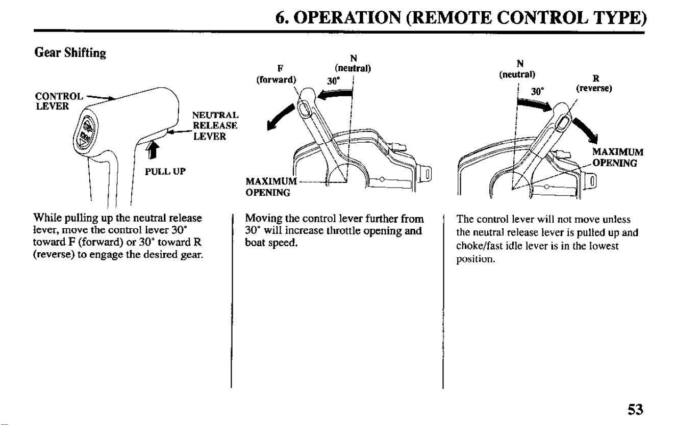
While pulling up the neutral release
lever, move the control lever 30
toward F (forward) or 30’ toward R
(reverse) to engage the desired gear.
Moving the control lever further from
30” will increase throttle opening and
boat speed.
N
(neutral)
i 30”
R
(reverse)
The control
lever will not move unless
the neutral release lever is pulled up and
choke/fast idle lever is in the lowest
position.
53
6. OPERATION (REMOTE CONTROL TYIE’E)
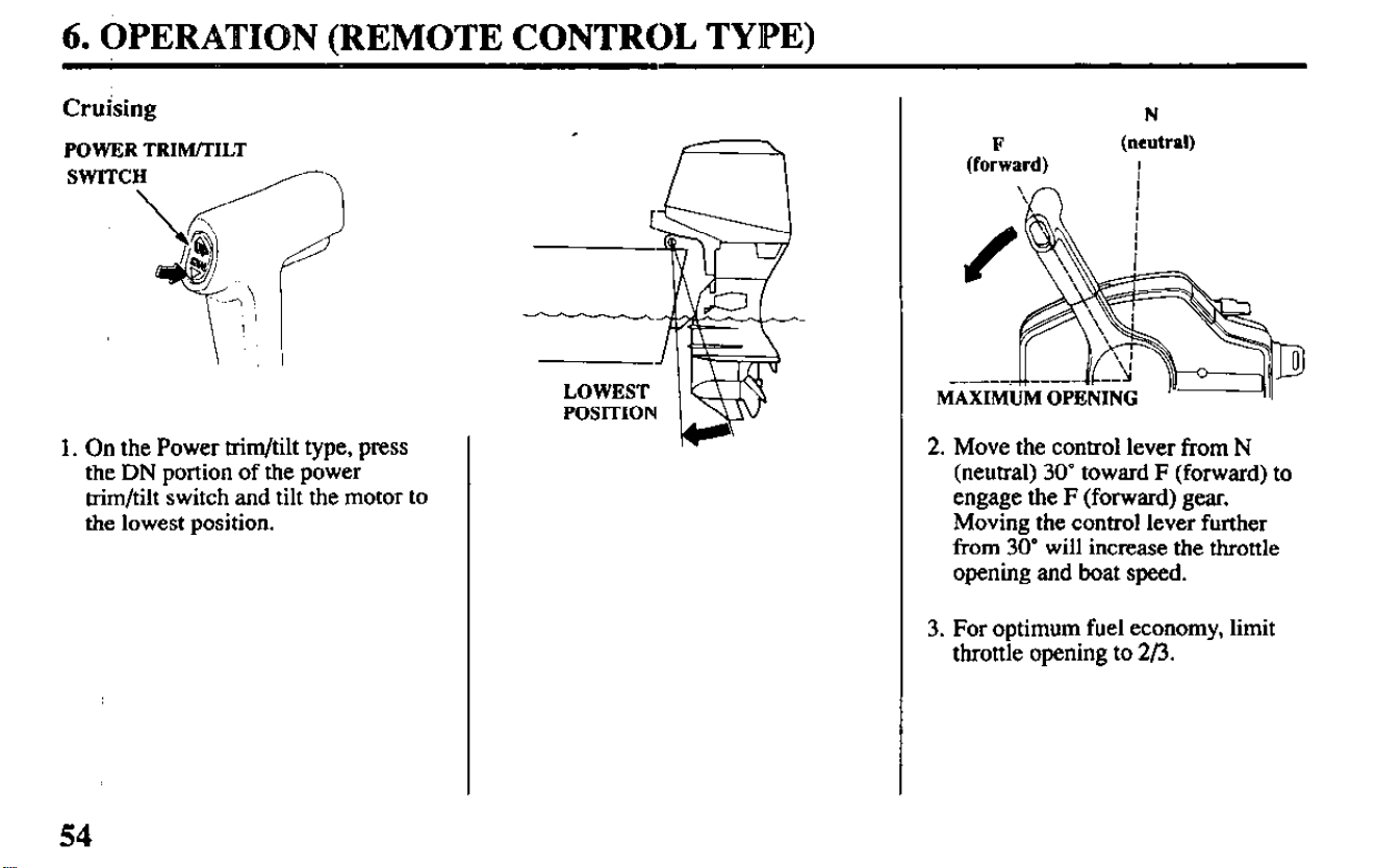
Cruising
POWER TRW/TILT
1. On the Power trim/tilt type, press
the DN portion of the power
trim/tilt switch and tilt the motor to
the lowest position.
54
(fo:ard)
N
(neutral)
I
2. Move the control lever from N
(neutral) 30’ toward F (forward) to
engage the F (forward) gear.
Moving the control lever further
from 30’ will increase the throttle
opening and boat speed.
3. For optimum fuel economy, limit
throttle opening to 2/3.
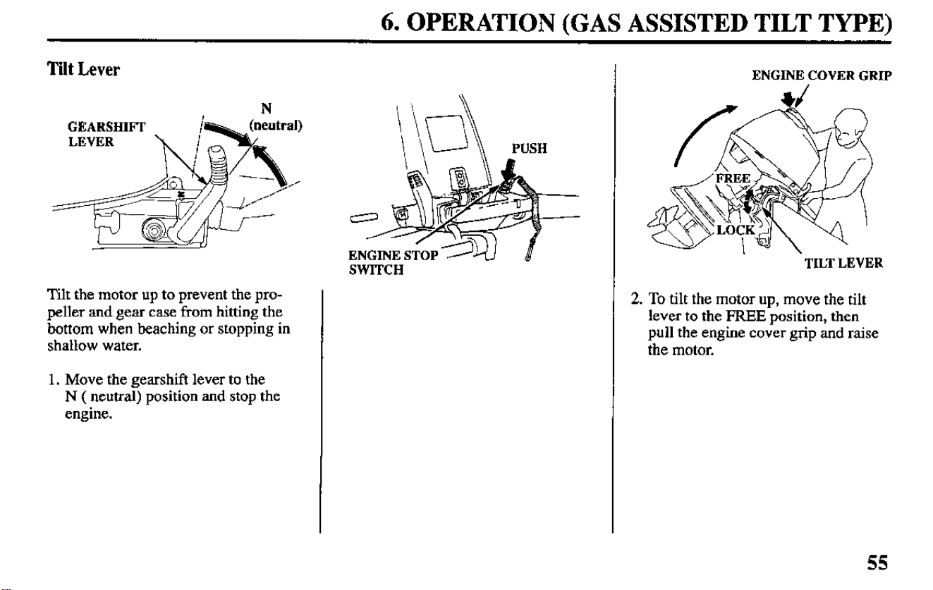
6. OPERATION (GAS ASSISTED TILT TYPE)
Tilt Lever
GEARSHIFT
Tilt the motor up to prevent the pro-
peller and gear case from hitting the
bottom when beaching or stopping in
shallow water.
1. Move the gearshift lever to the
N ( neutral) position and stop the
engine.
\ \u\\ PUSH
SWITCH
ENGINE COVER GRIP
‘TILT LEVER
2. To tilt the motor up, move the tilt
lever to the FREE position, then
pull the engine cover grip and raise
the motor.
55
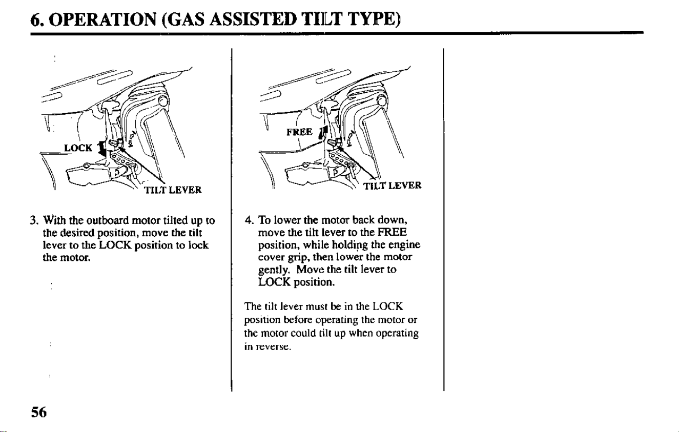
6. OPERATION (GAS ASSISTED TIILT TYPE)
3. With the outboard motor tilted up to
the desired position, move the tilt
lever to the LOCK position to lock
the motor.
4.
To lower the
motor
back down,
move the tilt lever to the FREE
position, while holding the engine
cover grip, then lower the motor
gently. Move the tilt lever
to
LOCK position.
The tilt lever must be in the LOCK
position before operating the motor or
the motor could tilt up when operating
in reverse.
56
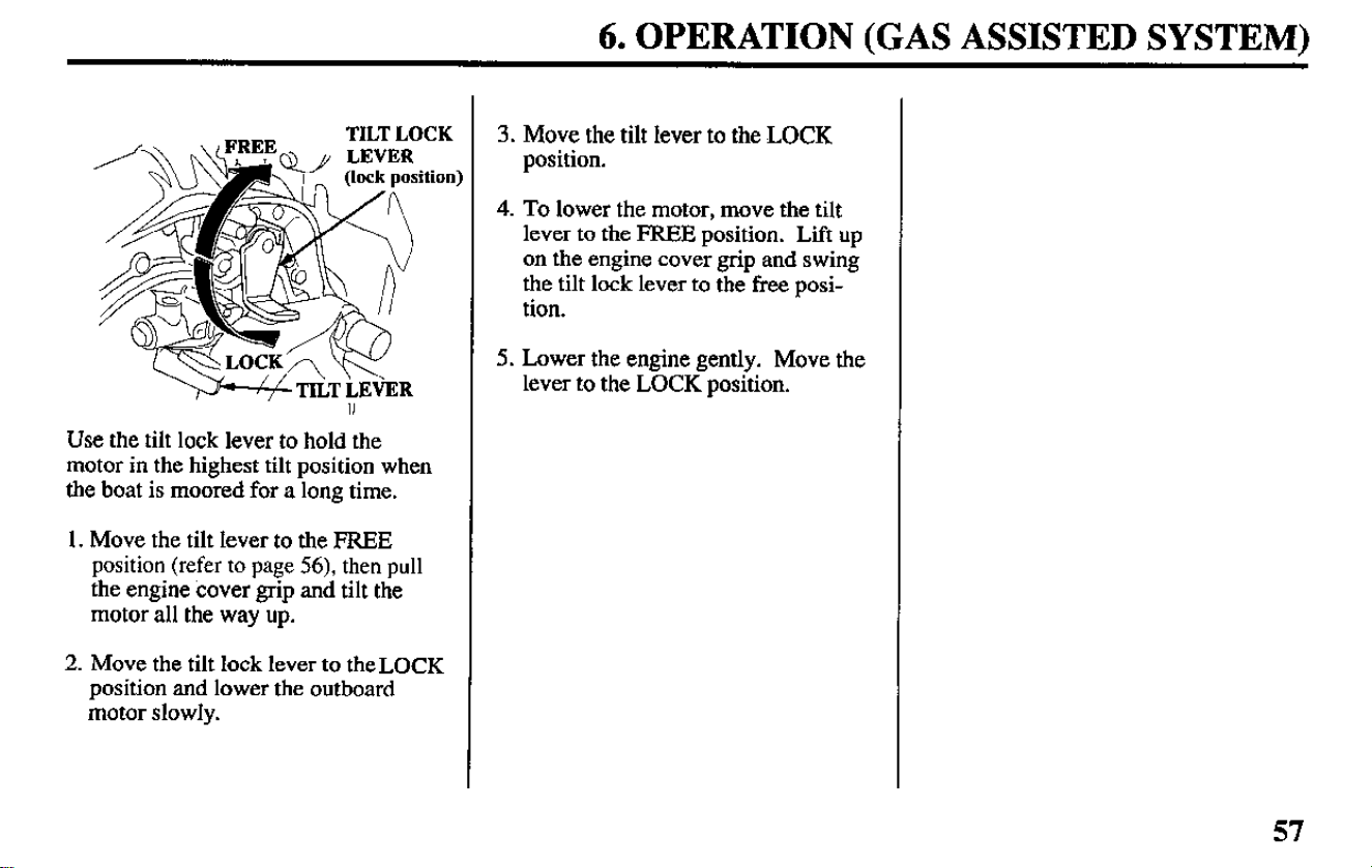
6. OPERATION (GAS ASSISTED SYSTEM)
TILT LOCK
II
Use the tilt lock lever to hold the
motor in the highest tilt position when
the boat is moored for a long time.
1. Move the tilt lever to the FREE
position (refer to page 56), then pull
the engine cover grip and tilt the
motor all the way up.
2. Move the tilt lock lever to theLOCK
position and lower the outboard
motor slowly.
3. Move the tilt lever to the LOCK
position.
4. To lower the motor, move the tilt
lever to the FREE position. Lift up
on the engine cover grip and swing
the tilt lock lever to the free posi-
tion.
5. Lower the engine gently. Move the
lever to the LOCK position.
57
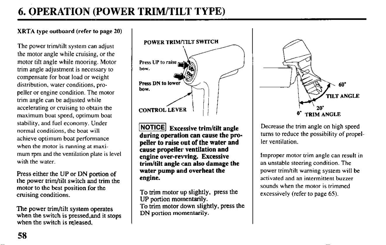
6. OPERATION (POWER TRIFdTILT TYPE)
XRTA type outboard (refer to page 20)
The power trim/tilt system can adjust
the motor angle while cruising, or the
motor tilt angle while mooring. Motor
trim angle adjustment is necessary to
compensate for boat load or weight
distribution, water conditions, pro-
peller or engine condition. The motor
trim angle can be adjusted while
accelerating or cruising to obtain the
maximum boat speed, optimum boat
stability, and fuel economy. Under
normal conditions, the boat will
achieve optimum boat performance
when the motor is running at maxi-
mum t-pm and the ventilation plate is level
with the water.
Press either the UP or DN portion of
the power trim/Mt switch and trim the
motor to the best position for the
cruising conditions.
The power trim/tilt system operates
when the switch is pressed,and it stops
when the switch is released.
POWER TRIMfllLT SWITCH
-
&T
Press UP
tu raise p
db
bow.
Press DN to
lower
bOW.
CONTROL LEVER
INOTICE] Excessive trim/tilt angle
during operation can cause the pro-
peller to raise out of the water and
cause propeller ventilation and
engine over-revving. Excessive
trim/tilt angle rzn also damage the
water pump and overheat the
engine.
To trim motor up slightly, press the
UP portion momentarily.
To trim motor down slightly, press the
DN portion momentarily.
I
’ 20’
0’ TRIM ANGLE
Decrease the trim angle on high speed
turns to reduce the possibility of prope
ler ventilation.
!I-
Improper motor trim angle can result in
an unstable steering condition. The
power trim/tilt warning system will be
activated and an intermittent buzzer
sounds when the motor is trimmed
excessively (refer to page 65).
58
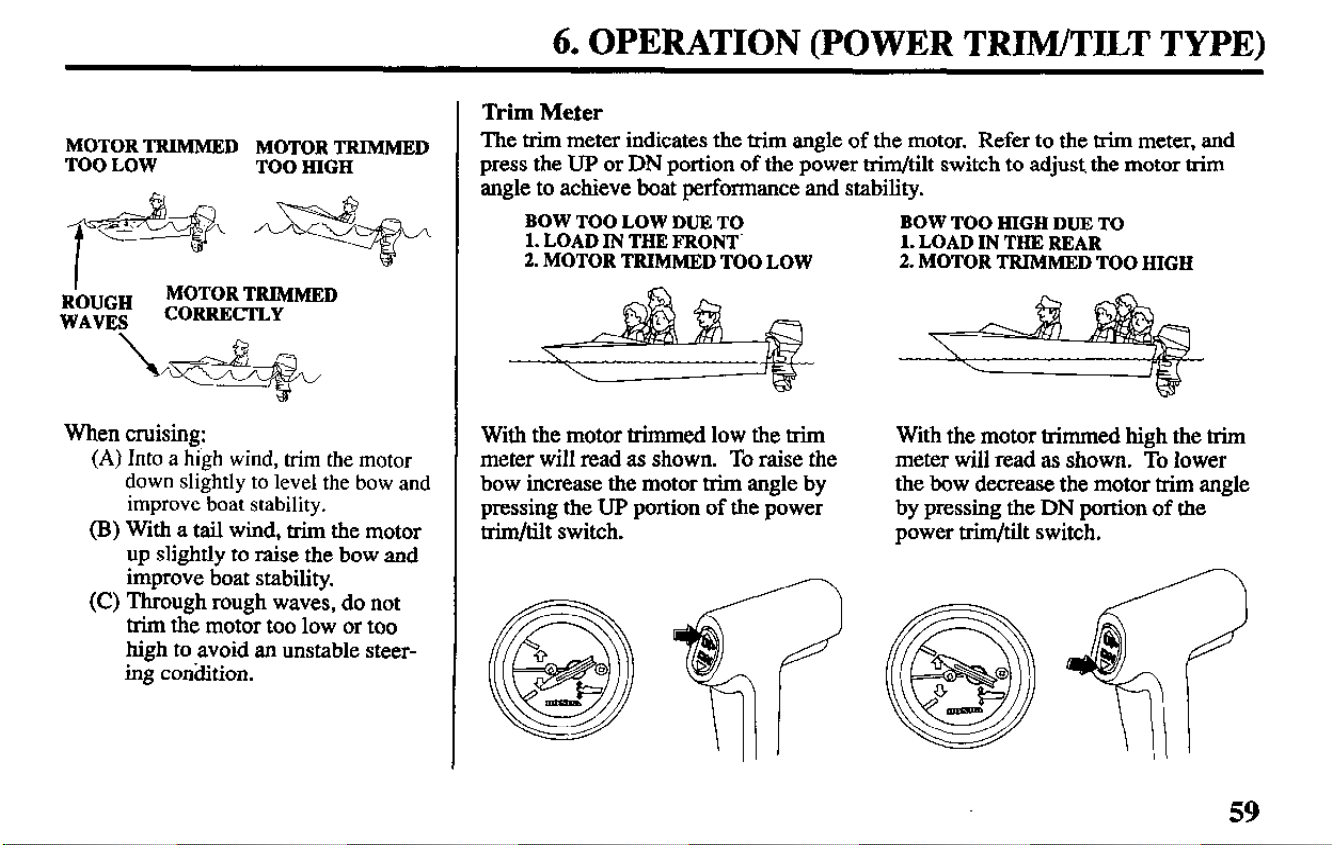
6. OPERATION (POWER TRIM/TILT TYPE)
MOTOR TRIMMED MOTOR TRIMMED
TOO LOW
TOO HIGH
R’OIJGH
MOTOR TRIMMED
WAVES
CORRECTLY
When cruising:
(A) Into a high wind, trim the motor
down slightly to level the bow and
improve boat stability.
(B) With a tail wind, trim the motor
up slightly to raise the bow and
improve boat stability.
(C) Through rough waves, do not
trim the motor too low or too
high to avoid an unstable steer-
ing condition.
‘lkim Meter
The trim meter indicates the trim angle of the motor.
Refer to the trim meter, and
press the UP or DN portion of the power trim/tilt switch to adjust. the motor trim
angle to achieve boat performance and stability.
BOW TOO HIGH DUE TO
1. LOAD IN THE REAR
2. MOTOR TRIMMED TOO HIGH
BOW TOO LOW DUE TO
1. LOAD IN THR FRONT’
2. MOTOR TRIMMED TOO LOW
With the motor trimmed low the trim
meter will read as shown. To raise the
bow increase the motor trim angle by
pressing the UP portion of the power
trim/tilt switch.
With the motor trimmed high the trim
meter will read as shown. To lower
the bow decrease the motor trim angle
by pressing the DN portion of the
power trim/tilt switch.
59
6.~PERATIOlV (POWER TRIM/TILT TYPE)
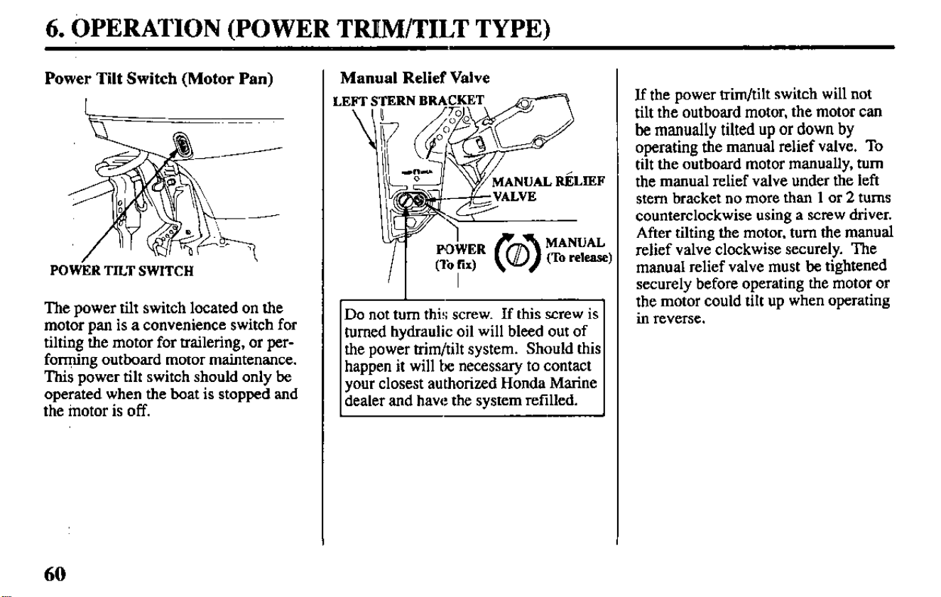
Power Tilt Switch (Motor Pan)
POWkR TILT SWITCH
The power tilt switch located on the
motor pan is a convenience switch for
tilting the motor for trailering, or per-
forming outboard motor maintenance.
This power tilt switch should only be
operated when the boat is stopped and
the motor is off.
Manual Relief Valve
.IEF
MANUAL
(To release)
Do not turn this screw. If this screw is
turned hydraulic oil will bleed out of
the power trim/tilt system. Should this
happen it will be necessary to contact
your closest authorized Honda Marine
dealer and have the system refilled.
If the power trim/tilt switch will not
tilt the outboard motor, the motor can
be manually tilted up or down by
operating the manual relief valve. To
tilt the outboard motor manually, turn
the manual relief valve under the left
stem bracket no more than 1 or 2 turns
counterclockwise using a screw driver.
After tilting the motor, turn the manual
relief valve clockwise securely. The
manual relief valve must be tightened
securely before operating the motor or
the motor could tilt up when operating
in reverse.
6. OPERATION (POWER TRIM/TILT TYPE)
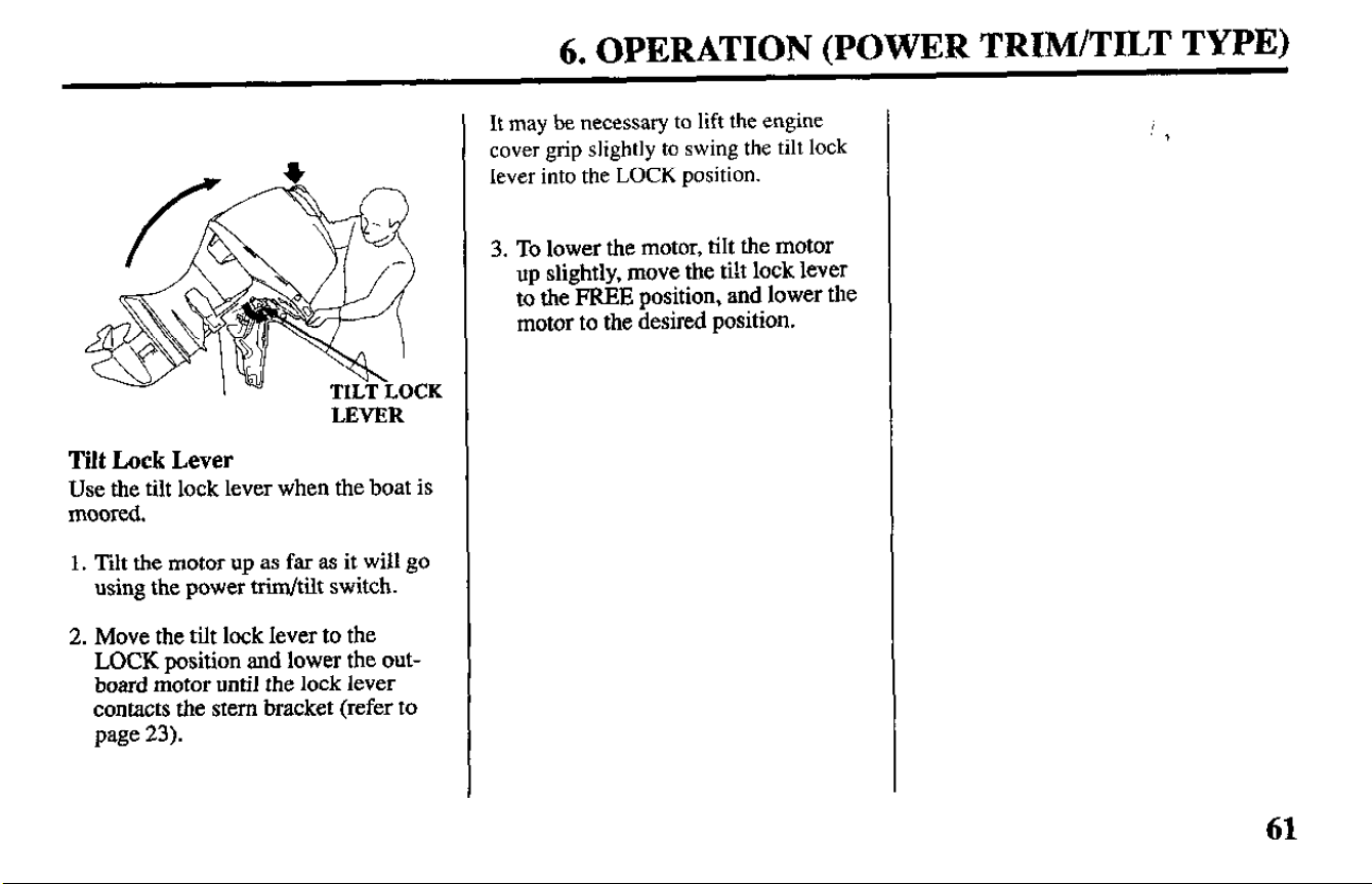
LEVER
Tilt Lock Lever
Use the tilt lock lever when the boat is
moored.
1. Tilt the motor up as far as it will go
using the power trim/tilt switch.
2. Move the tilt lock lever to the
LOCK position and lower the out-
board motor until the lock lever
contacts the stem bracket (refer to
page 23).
It may be necessary to lift the engine
cover grip slightly to swing the tilt lock
lever into the LOCK position.
3. To lower the motor, tilt the motor
up slightly, move the tilt lock lever
to the FREE position, and lower the
motor to the desired position.
,
*
61
6. OPERATIBFJ
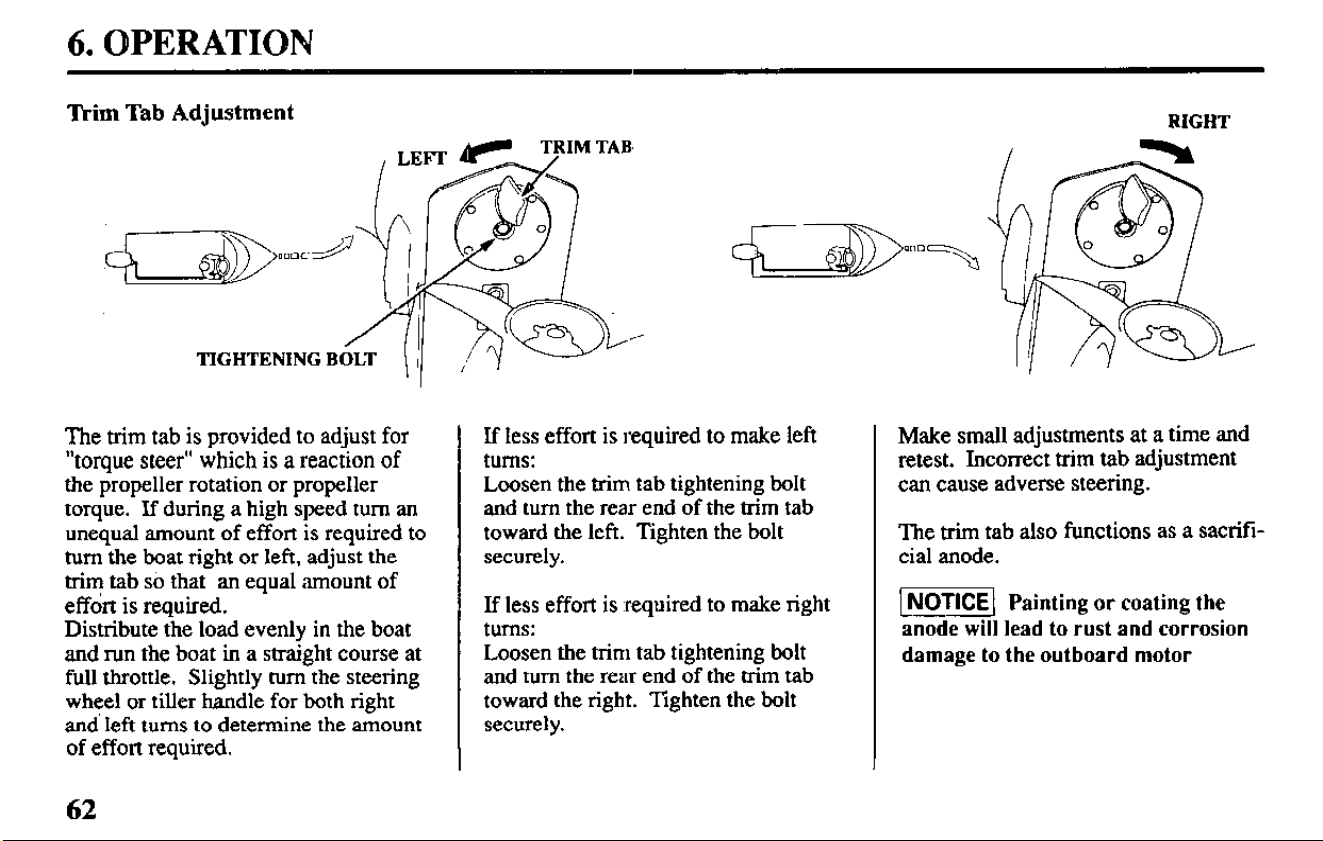
‘Ikim Tab Adjustment
TIGHTENING B
The trim tab is provided to adjust for
“torque steer” which is a reaction of
the propeller rotation or propeller
torque. If during a high speed turn an
unequal amount of effort is required to
turn the boat right or left, adjust the
trim tab so that an equal amount of
effort is required.
Distribute the load evenly in the boat
and run the boat in a straight course at
full throttle. Slightly turn the steering
wheel or tiller handle for both right
and’ left turns to determine the amount
of effon required.
If less effort is required to make left
turns:
Loosen the trim tab tightening bolt
and turn the rear end of the trim tab
toward the left. Tighten the bolt
securely.
If less effort is .required to make right
turns:
Loosen the trim tab tightening bolt
and turn the rear end of the trim tab
toward the right. Tighten the bolt
securely.
Make small adjustments at a time and
retest. Incorrect trim tab adjustment
can cause adverse steering.
The trim tab also functions as a sacrifi-
cial anode.
-1 Painting or coating
the
anode will lead to rust and corrosion
damage to the outboard motor
62
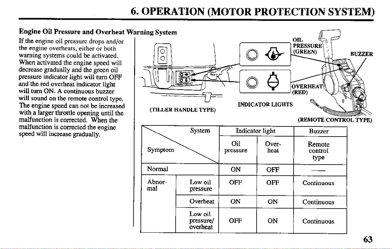
6. OPERATION (MOTOR PROTECTION SYSTEM)
Engine Oil Pressure and Overheat Warning System
If the engine oil pressure drops andfor
the engine overheats, either or both
warning systems could be activated.
When activated the engine speed will
decrease gradually and the green oil
pressure indicator light will turn OFF
and’the red overheat indicator light
will turn ON. A continuous buzzer
will sound on the remote control type.
The engine speed can not be increased
with a larger throttle opening until the
malfunction is corrected. When the
malfunction is corrected the engine
speed will increase gradually.
INDICATOR LIGHTS
63
6. OPERATION (MOTOR PROTECTION SYSTEM)
When the oil pressure warning sys-
tems is activated:
1. Stop the engine immediately and
check the engine oil level (refer to
pqze 29).
2.If the oil is up to the recommended
level, restart the engine. If the oil
pressure warning system stops after
30 seconds, the system is normal.
If the throttle
was closed suddenly after
cruising at full throttle, the engine speed
may drop below the specified idle speed.
This’could cause the oil pressure
warning system to activate momentarily.
3. If the oil pressure warning system
stays activated after 30 seconds,
return to the closest boat landing
and contact your closest authorized
Honda Marine dealer.
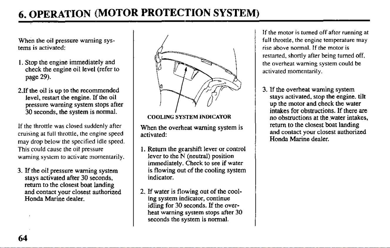
COOLING SYSTEM INDICATOR
When the overheat warning system is
activated:
1. Return the gearshift lever or control
lever to the N (neutral) position
immediately. Check to see if water
is flowing out of the cooling system
indicator.
2. If water is flowing out of the cool-
ing system indicator, continue
idling for 30 seconds. If the over-
heat warning system stops after 30
seconds the system is normal.
If the motor is turned off after running at
full throttle, the engine temperature may
rise above
normal.
If the
motor is
restarted, shortly after being
turned off,
the overheat warning system could be
activated momentarily.
3. If the overheat warning system
stays activated, stop the engine. tilt
up the motor and check the water
intakes for obstructiotls. If there are
no obstructions at the -water intakes,
return to the closest boat landing
and contact your closest authorized
Honda Marine dealer.
64
6. OPERATION (MOTOR PROTECTION SYSTEM)
Over-Rev Limiter
This outboard motor is equipped with
an engine over-rev limiter which acti-
vates when the engine speed increases
excessively. The over-rev limiter can
be activated while cruising, tilting up
the motor, or when ventilation occurs
during a sharp turn.
When the over-rev limiter is activated:
1 .Reduce the throttle opening immedi-
ately and check the trim angle.
23 the trim angle is correct but the
over-rev limiter stays activated,
stop-the engine and check the con-
dition of the outboard motor and
check the propeller for damage.
Correct or service as necessary,.
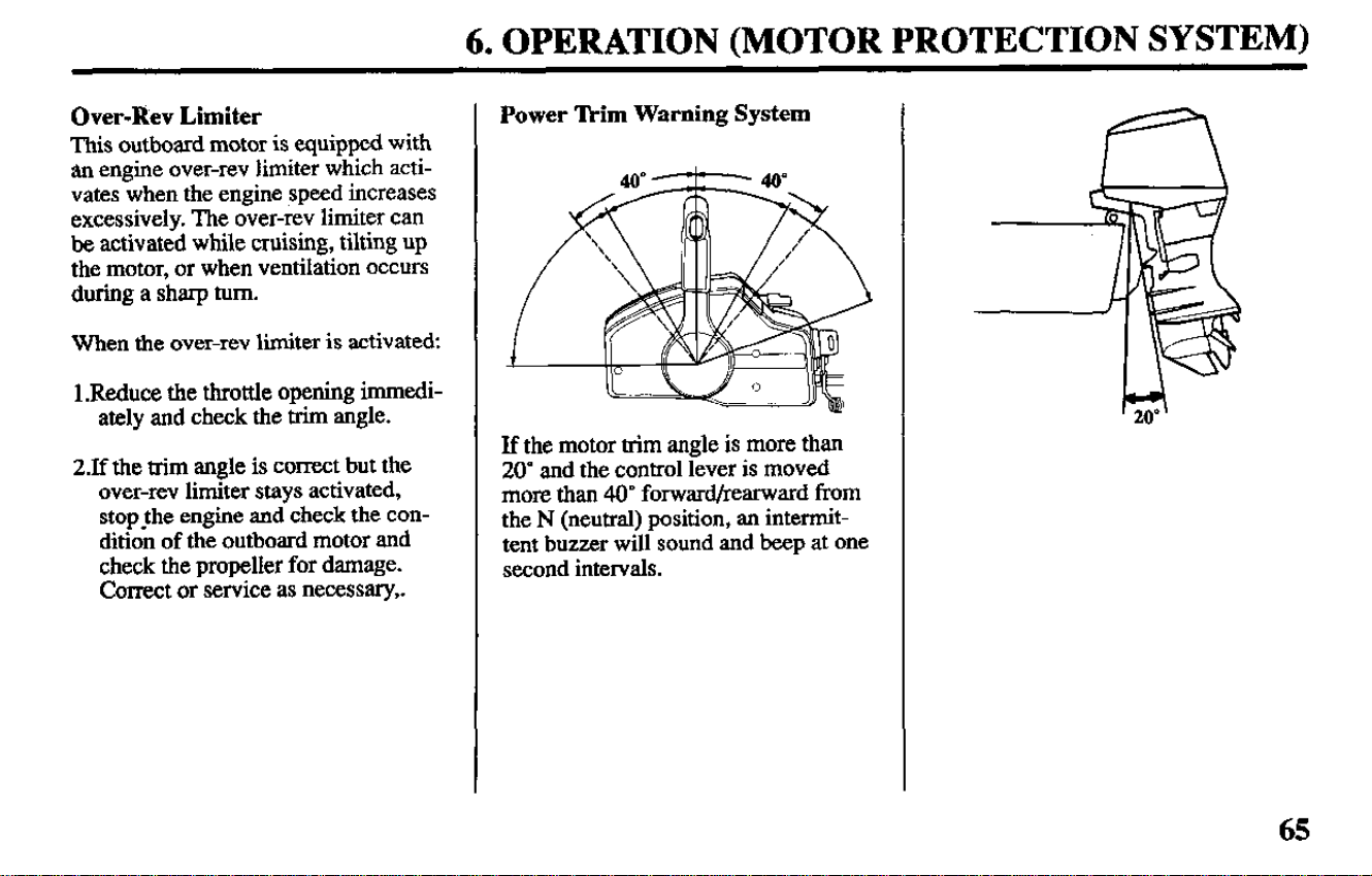
Power lkim Warning System
If the motor trim angle is more than
20” and the control lever is moved
more than 40’ forward/rearward from
the N (neutral) position, an intermit-
tent buzzer will sound and beep at one
second intervals.
65
6. OPERATION (MOTOR PROTECTION SYSTEM)
When the power trim warning system
is activated:
1. Immediately decrease the trim
angle by pressing the DN portion of
the power trim/tilt switch.
2. Immediately reduce the tiottle
opening to SLOW and Operate the
engine at low speed.
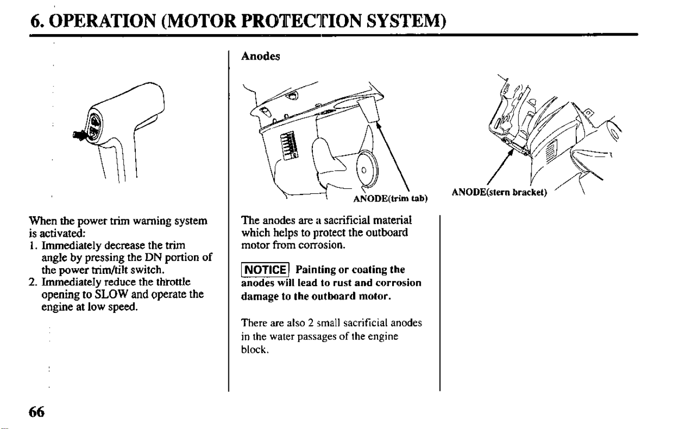
Anodes
The anodes are a skxificial material The anodes are a skxificial material
which helps to protect the outboard which helps to protect the outboard
motor from corrosion. motor from corrosion.
1 NOTICE) Painting or coating the
anodes will lead to rust and corrosion
damage to the outboard motor.
There are also 2 small sacrificial anodes
in the water passages of the engine
block.
66
6. OPERATION
Shallow Water Operation
-[Excessive trim/tilt angle
during operation can cause the pro-
peller to raise out of the water and
cause propeller ventilation and
engine over-revving. Excessive
trim/tilt angle can also damage the
water pump and overheat the
engine.
When operating in shallow water, tilt
the motor up to prevent the propeller
and gear case from hitting the bottom
(refer to pages 55 and 58). With the
motor tilted up, operate the motor at
low speed.
Monitor the cooling system indicator
for water discharge. Be sure that the
motor is not tilted so high that the
water intakes are out of the water.
If an excessive amount of throttle is
used when operating in forward gear,
the motor will return to the transom
angle adjusting rod.
(Gas assisted tilt type).
If the motor trim angle is more than
20” and the control lever is moved
more than 40’ forward/rearward from
the N (neutral) position, the power
trim warning system will be activated
(refer to page 65).
(Power trim/tilt type).
67
6. OPERATION
High Altitude Operation
At high altitude, the standard carburetor air-fuel mixture
will be too rich. Performance will decrease, and fuel con-
sumption will increase. A very rich mixture will also foul
the spark plugs and cause hard starting.
High altitude performance can be improved by specific
modifications to the carburetors. If you always operate
your outboard at altitudes above 6,000 feet (1,800 meters)
have an authorized Honda Marine dealer perform this car-
buretor modification.
Even with carburetor modification, engine horsepower
will decrease about 3.5% for each I.000 foot (300 meter)
increase in altitude. The effect of altitude on horsepower
will be greater than this if no carburetor modification is
made.
NOTICE When the carburetors have been modified
for high altitude operation, the air-fuel mixture will be
too lean for low altitude use. Operation at altitudes be-
low 6,000 feet (1,800 meters) with modified carbure-
tors may cause the engine to overheat and result in
serious engine damage. For use at low altitudes, have
an authorized Honda Marine dealer return the carbu-
retors to original factory specifications.
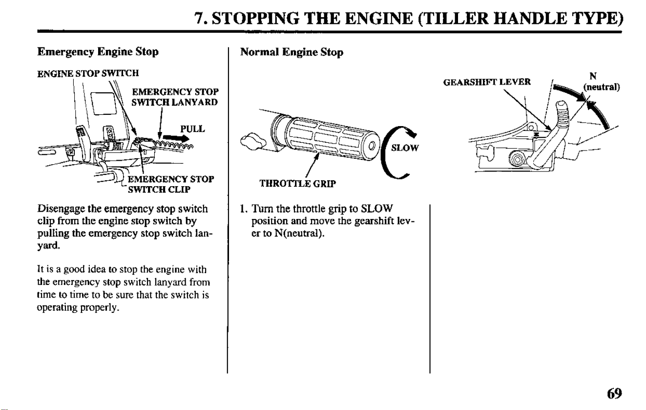
7. STOPPING THE ENGINE (TILLER HANDLE TYPE)
Emergency Engine Stop
ENGINE STOP SWITCH
EMERGENCY STOP
SWITCH LANYARD
L SWITCH CLIP
Disengage the emergency stop switch
clip from the engine stop switch by
pulling the emergency stop switch lan-
yard.
It is a good idea to stop the engine with
the emergency stop switch lanyard from
time to time to be sure that the switch is
operating properly.
Normal Engine Stop
THROTTLE GRIP
1. Turn the throttle grip to SLOW
position and move the gearshift lev-
er to N(neutral).
GEARSHIFT LEVER
,’
N
69
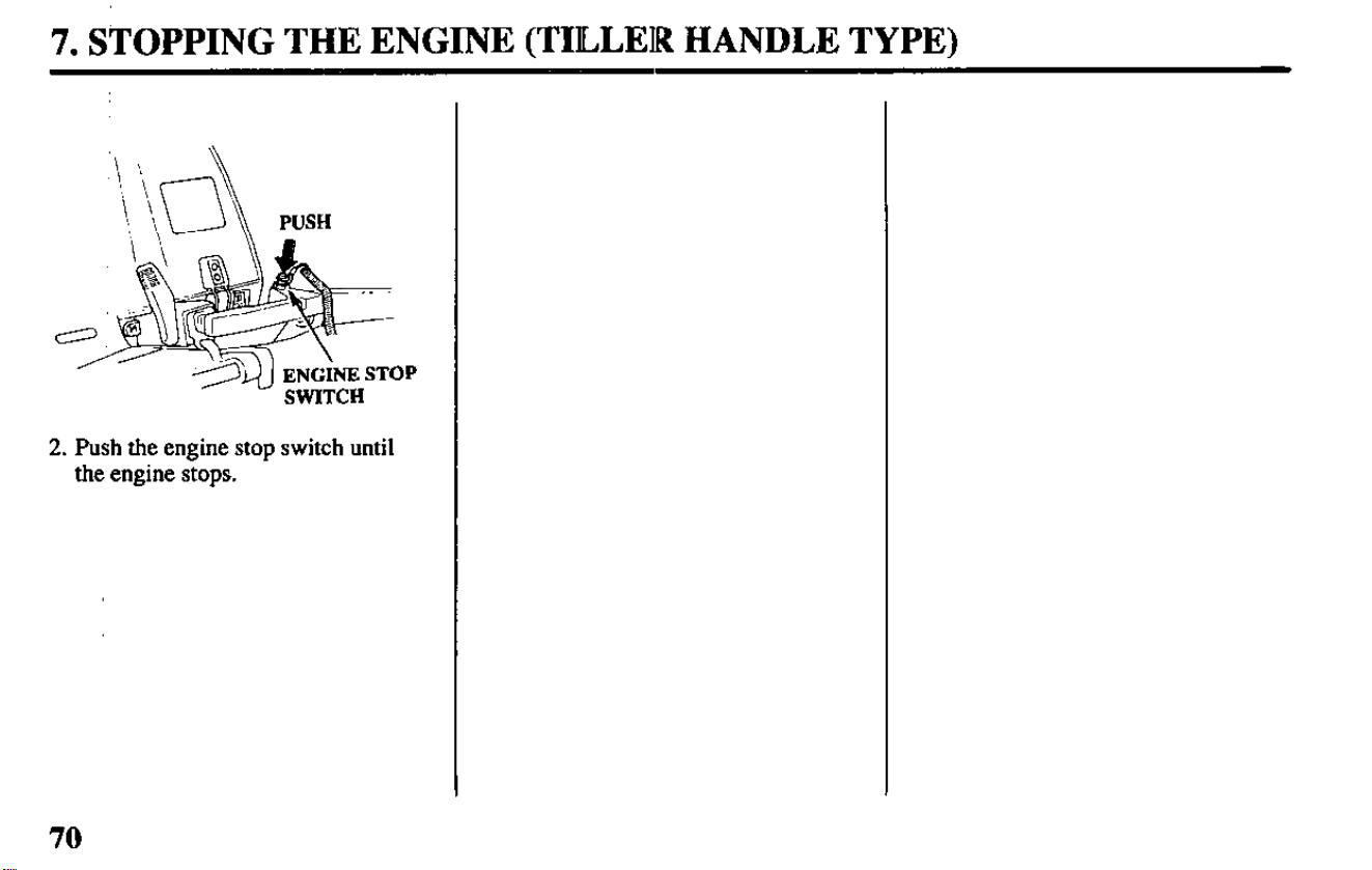
7. STOPPING THE ENGINE (TILLEIR HANDLE TYPE)
PUSH
2. Push the engine stop switch until
the engine stops.
70
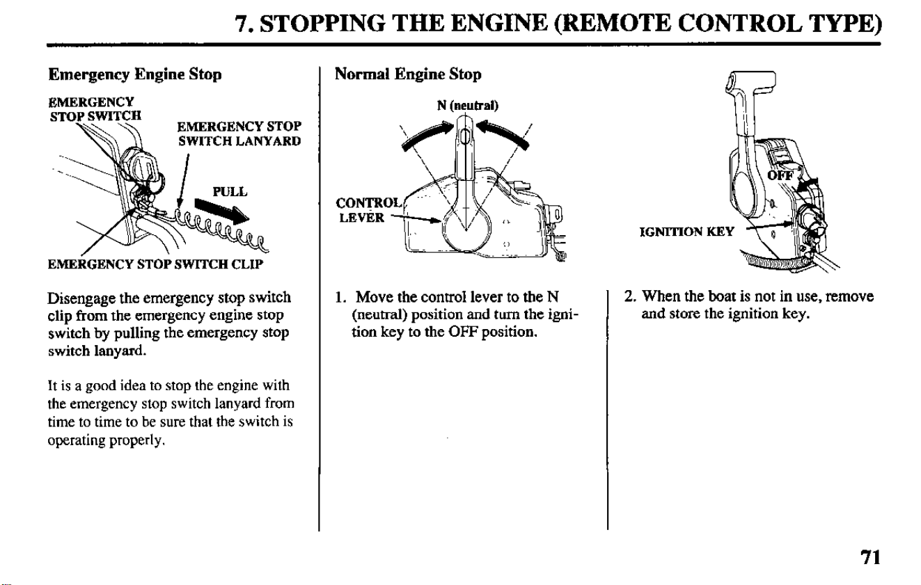
7. STOPPING THE ENGINE (REMOTE CONTROL TYPE)
Emergency Engine Stop
EMERGENCY
EMERGENCY STOP
\\\\ \\
SWITCH LANYARD
EMERGENCY STOP SWITCH CLIP
Disengage the emergency stop switch
clip from the emergency engine stop
switch by pulling the emergency stop
switch lanyard.
It is a good idea to stop the engine with
the emergency stop switch lanyard from
time
to time to be sure that the switch is
operating properly.
Normal Engine Stop
N (neutral)
1. Move the control lever to the N
(neutral) position and turn the igni-
tion key to the OFF position.
IGNITION KEY
2.
When the boat is not in use, remove
and store the ignition key.
71
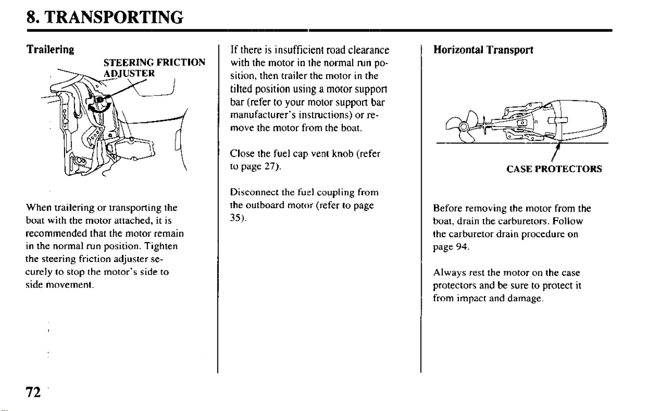
8. TRANSPORTING
Trailering
STEERING FRICTION
When trailering or transporting the
boat with the motor attached, it is
recommended that the motor remain
in the normal run position. Tighten
the steering friction adjuster se-
curely lo stop the motor’s side to
side tiovement.
If there is insufficient road clearance
with the motor in the normal run po-
sition, then trailer the motor in the
tilted position using a motor support
bar (refer to your motor support bar
manufacturer’s instructions) or re-
move the motor from the boat.
Close the fuel cap vent knob (refer
to page 27).
Disconnect the fuel coupling from
the outboard motor (refer to page
35).
Horizontal Transport
CASE PROTECTORS
Before removing the motor from the
boat, drain the carburetors. Follow
the carburetor drain procedure on
page 94.
Always rest the motor on the case
protectors and be sure to protect it
from impact and damage.
72
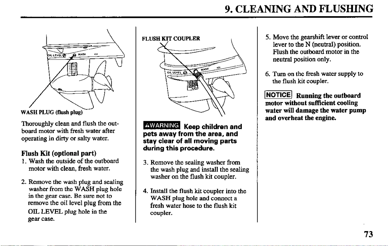
9. CLEANING AND FLUSHING
I
w
WASH PLUG (flush plug)
Thoroughly clean and flush the out-
board motor with fresh water after
operating in dirty or salty water.
Flush Kit (optional part)
1. Wash the outside of the outboard
motor with clean, fresh water.
2. Remove the wash plug and sealing
washer from the WASH plug hole
in the gear case. Be sure not to
remove the oil level plug from the
OIL LEVEL plug hole in the
gear case.
FLUSH KIT COUPLER
I
B Keep children and
pets away from the area, and
stay clear of all moving parts
during this procedure.
3. Remove the sealing washer from
the wash plug and install the sealing
washer on the flush kit coupler.
4. Install the flush kit coupler into the
WASH plug hole and connect a
fresh water hose to the flush kit
coupler.
5. Move the gearshift lever or control
lever to the N (neutral) position.
Blush the outboard motor in the
neutral position only.
6. Turn on the fresh water supply to
the flush kit coupler.
I- Running the outboard
motor without sufficient cooling
water will damage the water pump
and overheat the engine.
73
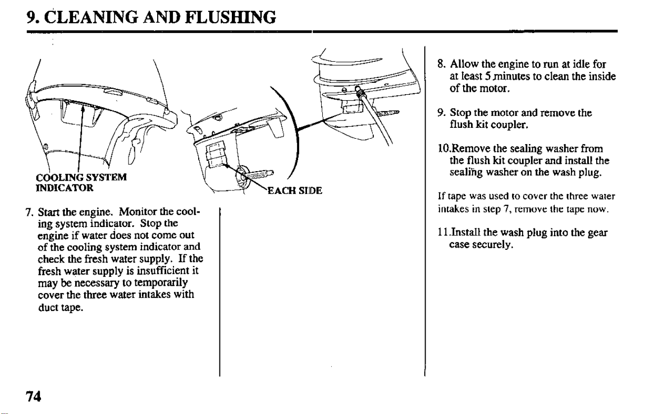
9. CLEANING AND FLUSHING
CdoLINb SYSTEM
INDICATOR
7. Start the engine. Monitor the cool-
ing system indicator. Stop the
engine if water does not come out
of the cooling system indicator and
check the fresh water supply. If the
fresh water supply is insufficient it
may be necessary to temporarily
cover the three water intakes with
duct tape.
8. Allow the engine to run at idle for
at least 5 minutes to clean the inside
of the motor.
9. Stop the motor and remove the
flush kit coupler.
lO.Remove the sealing washer from
the flush kit coupler and install the
sealing washer on the wash plug.
If tape was used to cover the three water
intakes in step 7, remove the tape now.
11 .Install the wash plug into the gear
case securely.
74
10. MAINTENANCE
Periodic maintenance and adjustment
are important to keep the motor in the
best operating condition. Service and
inspect according to the MAINTENA-
NCE SCHEDULE.
Stop the engine before performing any
maintenance.
If it is necessary to run the engine
make sure the area is well ventilated.
Never run the engine in an enclosed or
confined area.
-
Exhaust contains
poisonous carbon monoxide
gas; exposure can cause loss of
consciousness and may lead to
death.
m Running the outboard
motor without sufficient cooling
water will damage the water pump
and overheat the engine.
To maintain the cooling system effi-
ciency, flush the outboard motor with
fresh water after operating in salt
water or dirty water. Make sure there
is at least 2 inches of water above the
ventilation plate. Or follow the flushing
procedure (refer to pages 73 and 74).
75
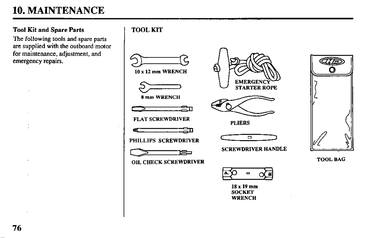
10. MAINTENANCE
Tool Kit and Spare Parts
The following tools and spare parts
are supplied with the outboard motor
for maintenance, adjustment, and
emergency repairs.
TOOL KIT
n
10 x 12
mm
WRENCH
w
8
mm
WRENCZI
FLAT SCREWDRIVER
-==n
PHILLIPS SCREWDRIVER
-=
OIL CHECK SCREWDRIVER
PLIERS
C
0
3
SCREWDRIVER HANDLE
TOOL BAG
18 x 19
mm
SOCKET
WRENCH
76
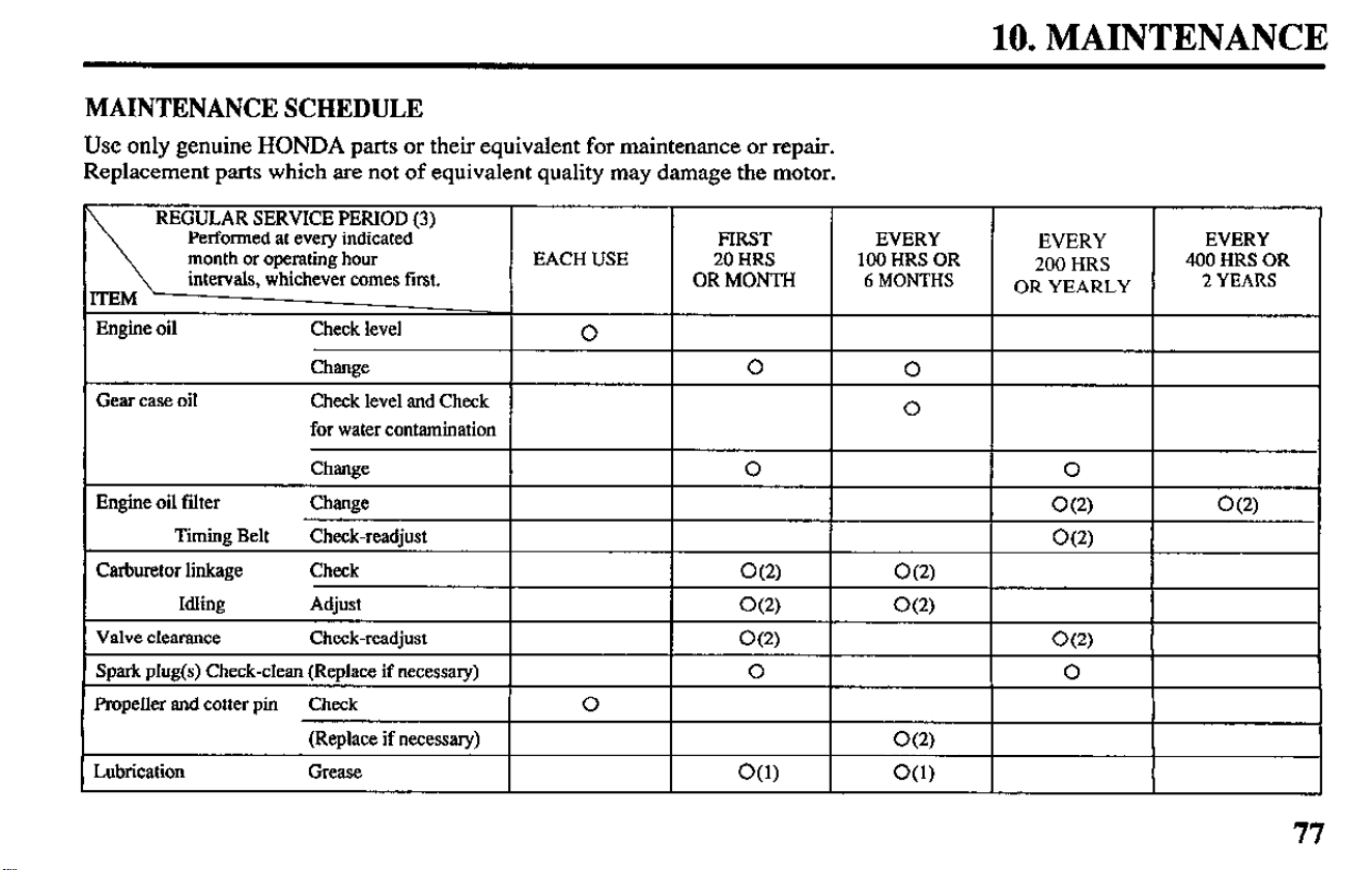
10. MAINTENANCE
MAINTENANCE SCHEDULE
Use only genuine HONDA parts or their equivalent for maintenance or repair.
Replacement parts which are not of equivalent quality may damage the motor.
REGULAR SERVICE PERIOD (3)
Performed at every indicated FIRST
EVERY
EVERY
EVERY
month or operating hour EACH USE 20 HRS
100 HRS OR
200 HRS
400 HRS OR
intervals, whichever comes first. OR MONTH
6 MONTHS
OR YEARLY
2 YEARS
Engine oil Check level
0
Change
0
0
Gear case oil Check level and Check
0
for water contamination
Engine oil filter
Change
0 0
Change
O(2)
O(2)
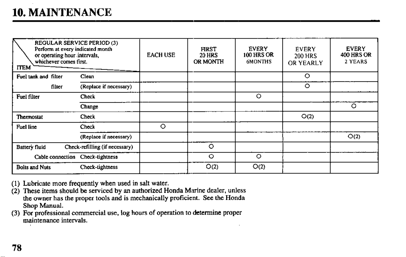
10. MAINTENANCE
REGULAR SERVICE PERIOD (3)
Perform at every indicated month
or operating
hour,
intervals,
whichever comes first.
Fuel tank and filter
ClCUl
filter
(Replace if necessary)
FIRST
EVERY
EVERY
EVERY
EACH USE
20 HRS
100 HRS OR
200 HRS
400 HRS OR
OR MONTH
6MONTHS
OR YEARLY
2 YEARS
0
0
I
Fuel filter
Check 0
Chanee I
I
I
0
I
l%ermostat
Check
I
I I I
O(2)
1
I
Fuel line
Check
(Replace if necessary)
Battee fluid
Check-refilling (if necessary)
Cable connection Check-tightness
Bolts and Nuts
Check-tighmess
0
O(2)
0
0 0
O(2) O(2)
(1) Lubricate more frequently when used in salt water.
(2) These items should be serviced by an authorized Honda Marine dealer, unless
the owner has the proper tools and is mechanically proficient. See the Honda
Shop Manual.
(3) For professional commercial use, log hours of operation to determine proper
maintenance intervals.
78
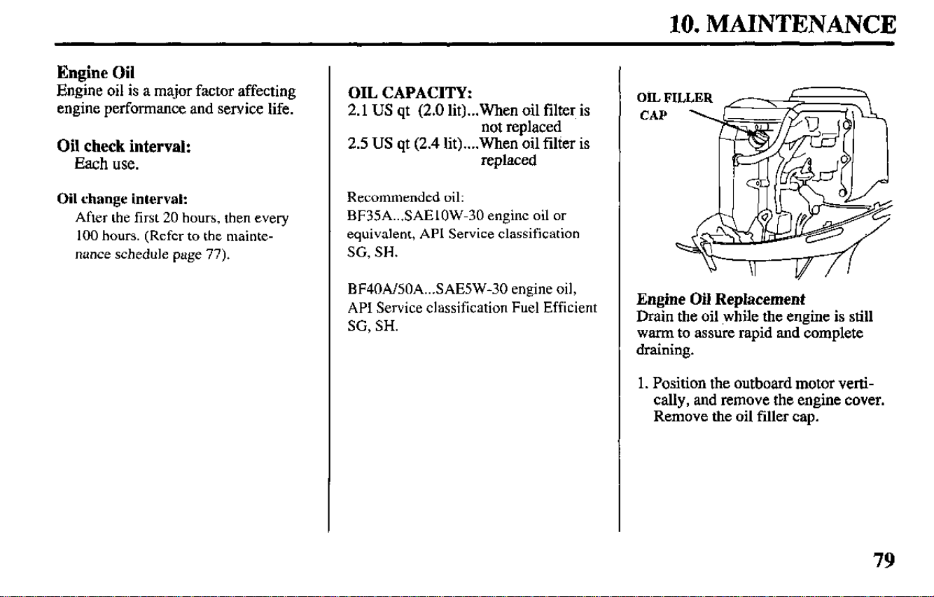
10. MAINTENANCE
Engine Oil
Engine oil is a major factor affecting
engine performance and service life.
Oil check interval:
Each use.
Oil change interval:
After the first 20 hours, then every
100 hours. (Refer to the mainte-
nance schedule page 77).
OIL CAPACITY:
2.1 US qt (2.0 lit)...When oil filter is
not replaced
2.5 US qt (2.4 lit)....When oil filter is
replaced
Recommended oil:
BF35A...SAElOW-30 engine oil or
equivalent, API Service classification
SG, SH.
BF40Al50A...SAE5W-30 engine oil,
API Service classification Fuel Efficient
SG. SH.
Engine Oil Replacement
Drain the oil while the engine is still
warm to assure rapid and complete
draining.
1. Position the outboard motor verti-
cally, and remove the engine
cover.
Remove the oil filler cap.
79
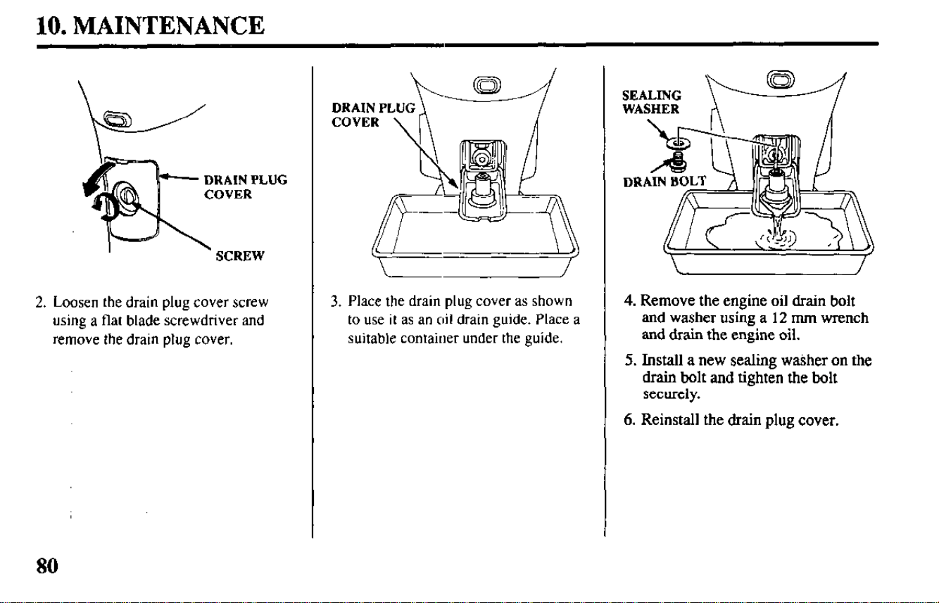
10. MAINTENANCE
DHAINPLUG
2. Loosen the drain plug cover screw
using a flat blade screwdriver and
remove the drain plug cover.
80
3. Place the drain plug cover as shown
to use it as an oil drain guide. Place a
suitable contaiuer under the guide.
4. Remove the engine oil drain bolt
and washer using a 12 mm wrench
and drain the engine oil.
5. Install a new sealing washer on the
drain bolt and tighten the bolt
securely.
6. Reinstall the drain plug cover.
10. MAINTENANCE
7. Refill to the upper level mark on the
oil level dipstick with the recom-
mended oil.
NOTE: To ,avoid incorrect gauging
of the engine oil level, inspect the oil
level when the engine has cooled. The
outboard motor needs to be in the
vertical position.
8. Reinstall the oil filler cap.
Always wash your hands after handling
used oil.
Also, please dispose of used motor oil in
a manner that is compatible with the
environment. We suggest you take it in a
sealed container to your local service
station reclamation center. Do not throw
it in the trash, pour it on the ground,
down a drain, or into the water.
Gear Oil
Oil check interval:
Every 100 hours.
Oil change interval:
After the first 20 hours, then every
100 hours. (Refer to the mainte-
nance schedule page 77).
OIL CAPACITY:
0.53 US qt. (0.5 lit)
Recommended oil:
Outboard motor SAE 90 hypoid
gear oil API Service Classification
(GL-4 or GL-5).
81
10. ‘MAINTENANCE
LEVEL PLUG
Gear Oil Level/Check
1. Position the outboard motor verti-
cally.
2. Remove the level plug and see if oil
flows out. If no oil flows out, fill
through the drain plug hole until the
oil starts to flow out through the level
plug hole. If there is water in the oil,
the water will flow out first when the
drain plug is removed, or the oil will
be milky colored. If the oil appears
abnormal contact your closest
authorized Honda Marine dealer.
GEAR OIL BOITLE
A gear oil bottle is recommended to
fill the gear case.
The end of the drain plug is a mag-
net. Remove all metal particles from
the end of the drain plug before
reinstalling. Do not reinstall the drain
plug in the level plug hole.
3. Use new sealing washers and rein-
stall the level plug and drain plug
securely.
Gear Oil Change
1. Position the outboard motor verti-
cally.
2. Remove the level plug and drain
plug to drain the oil. Inject oil
through the drain plug hole until it
starts flowing out through the level
plug hole. Use new sealing washers
and reinstall the level plug first and
then the drain plug securely.
OIL CAPACITY:
0.53 US qt. (0.5 lit)
82
10. MAINTENANCE
Spark Plugs
To ensure proper engine operation, the
spark plugs must be properly gapped
and free of deposits.
Check-replace interval:
After the first 20 hours, then every
200 hours. (Refer to the mainte-
nance schedule page 77).
Recommended spark plug:
DR7EA (NGK),
X22ESR-U (NIPPON DENSO)
Use only the recommended spark
plugs or equivalent.
-1 Spark plugs which have
an improper heat range may cause
engine damage.
1. Allow the engine to cool. The spark
plugs will be hot if the engine has
been running.
2. Remove the engine cover.
PLUG CAPS
- v
3. Disconnect the spark plug caps
from the spark plugs.
4. Use the wrench and screwdriver
supplied in the tool kit to remove
the spark plugs.
5. Check the spark plugs. Replace the
spark plugs if there is apparent
wear, or if the insulators are
cracked or chipped. Clean the spark
*plugs with a wire brush if they are
to be reused.
: 0.024-0.028 in
(0.6-0.7
mm)
6. Measure the plug gaps with a spark
plug gap gauge.
The gaps should be 0.024-0.028 in
(0.6-0.7 mm). Correct as necessary
by carefully bending the side elec-
trode.
83
10. MAINTENANCE
7. Thread the plugs in by hand to pre-
vent cross threading.
8. After the spark plugs are seated,
tighten with a spark plug wrench to
compress the washers.
If installing new spark plugs, tighten i/2
turn after the spark plugs seat to com-
press the washers. If reinstalling used
spark plugs, tighten l/8-
l/4
turn after
the spark plugs seat to compress the
washers.
m The spark plugs must be
securely tightened. Aloose spark
plug can become very hot and may
cause engine damage.
Overtightening the spark plugs can
damage the threads.
Battery (not included)
Minimum requirements
12V-70AH marine cranking battery.
Maintenance interval
Refer
to the maintenance schedule
page 78 and your battery manufac-
turer’s instructions for servicing or
recharging information.
Check the battery cables to be sure
they are securely connected to the bat-
tery terminals. lighten if necessary.
If the battery terminals are corroded or
if recharging is necessary, remove the
battery from the boat to clean or
recharge.
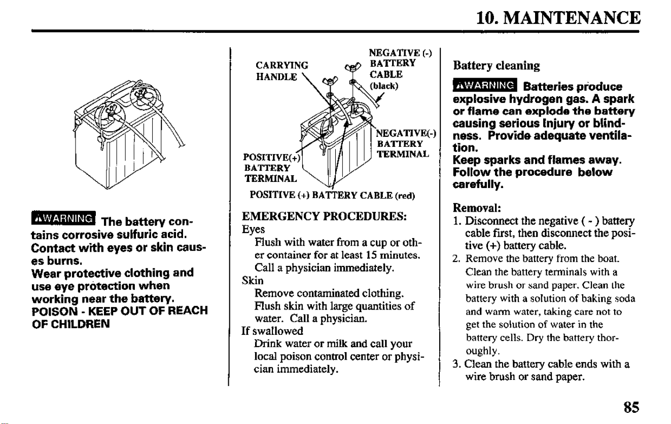
10. MAINTENANCE
tains corrosive sulfuric acid.
Contact with eyes or skin caus-
es burns.
Wear protective clothing and
use eye protection when
working near the
battery.
POISON - KEEP OUT OF REACH
OF CHILDREN
NEGATIVE (-)
CARRYING
~013 BATTERY
TERMINAL
POSITIVE
(+) BATTERY CABLE (red)
EMERGENCY PROCEDURES:
Eyes
Flush with water from a cup or oth-
er container for at least 15 minutes.
Call a physician immediately.
Skin
Remove contaminated clothing.
Flush skin with large quantities of
water. Call a physician.
If swallowed
Drink water or milk and call your
local poison control center or physi-
cian immediately.
Battery cleaning
B Batteries pioduce
explosive hydrogen gas. A spark
or flame can explode the battery
causing serious Injury or blind-
ness. Provide adequate ventila-
tion.
Keep sparks and flames away.
Follow the procedure below
carefully.
Removal:
1. Disconnect the negative ( - ) battery
cable first, then disconnect the posi-
tive (+) battery cable.
2. Remove the battery from the boat.
Clean the battery terminals with a
wire brush or sand paper. Clean the
battery with a solution of baking soda
and warm water, taking care not to
get the solution of water in the
battery cells. Dry the battery thor-
oughly.
3. Clean the battery cable ends with a
wire brush or sand paper.
85
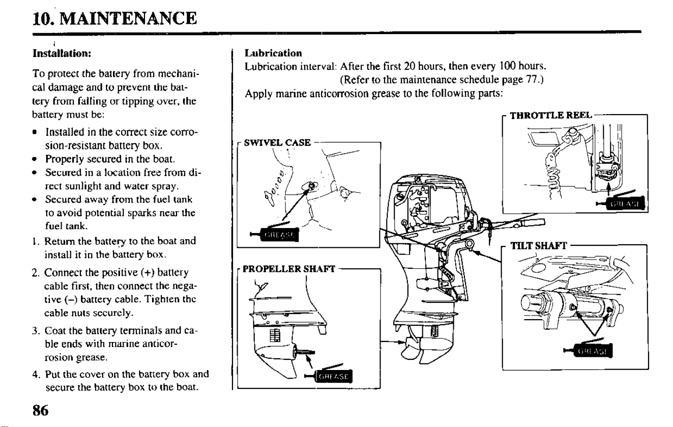
10. MAINTENANCE
Insthation:
To protect the battery from mechani-
cal damage and to prevent the bat-
tery from falling or tipping over, the
battery must be:
l
Installed in the correct size corro-
sion-resistant battery box.
l
Properly secured in the boat.
l
Secured in a location free from di-
rect sunlight and water spray.
l
Secured away from the fuel tank
to avoid potential sparks near the
fuel tank.
1. Return the battery to the boat and
install it in the battery box.
2. Connect the positive (+) battery
cable first, then connect the nega-
tive (-) battery cable. Tighten the
cable nuts securely.
3. Coat the battery terminals and ca-
ble ends with marine anticor-
rosion grease.
4, Put the cover on the battery box and
secure the battery box to the boat.
86
Lubrication
Lubrication interval: After the first 20 hours, then every 100 hours.
(Refer to the maintenance schedule page 77.)
Apply marine anticorrosion grease to the following parts:
r THROTI’LE REEL
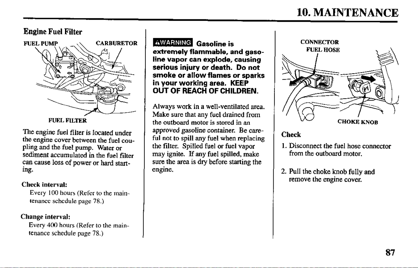
10. MAINTENANCE
Engine Fuel Filter
FUEL FILTER
The engine fuel filter is located under
the engine cover between the fuel cou-
pling and the fuel pump. Water or
sediment accumulated in the fuel filter
can cause loss of power or hard start-
ing.
Check interval:
Every
100 hours
(Refer
to the main-
tenance schedule page 78.)
Change interval:
Every 400 hours (Refer to the main-
tenance schedule page 78.)
w Gasoline is
extremely flammable, and gaso-
line vapor can explode, causing
serious injury
or
death. Do not
smoke or allow flames or sparks
in your working area. KEEP
OUT OF REACH OF CHILDREN.
Always work in a well-ventilated area.
Make sure that any fuel drained from
the outboard motor is stored in an
approved gasoline container. Be care-
ful not to spill any fuel when replacing
the filter. Spilled fuel or fuel vapor
may ignite. If any fuel spilled, make
sure the area is dry before starting the
engine.
CONNECTOR
FUEL HOSE
.
,\
Check
1. Disconnect the fuel hose connector
from the outboard motor.
2. Pull the choke knob fully
and
remove the engine cover.
87
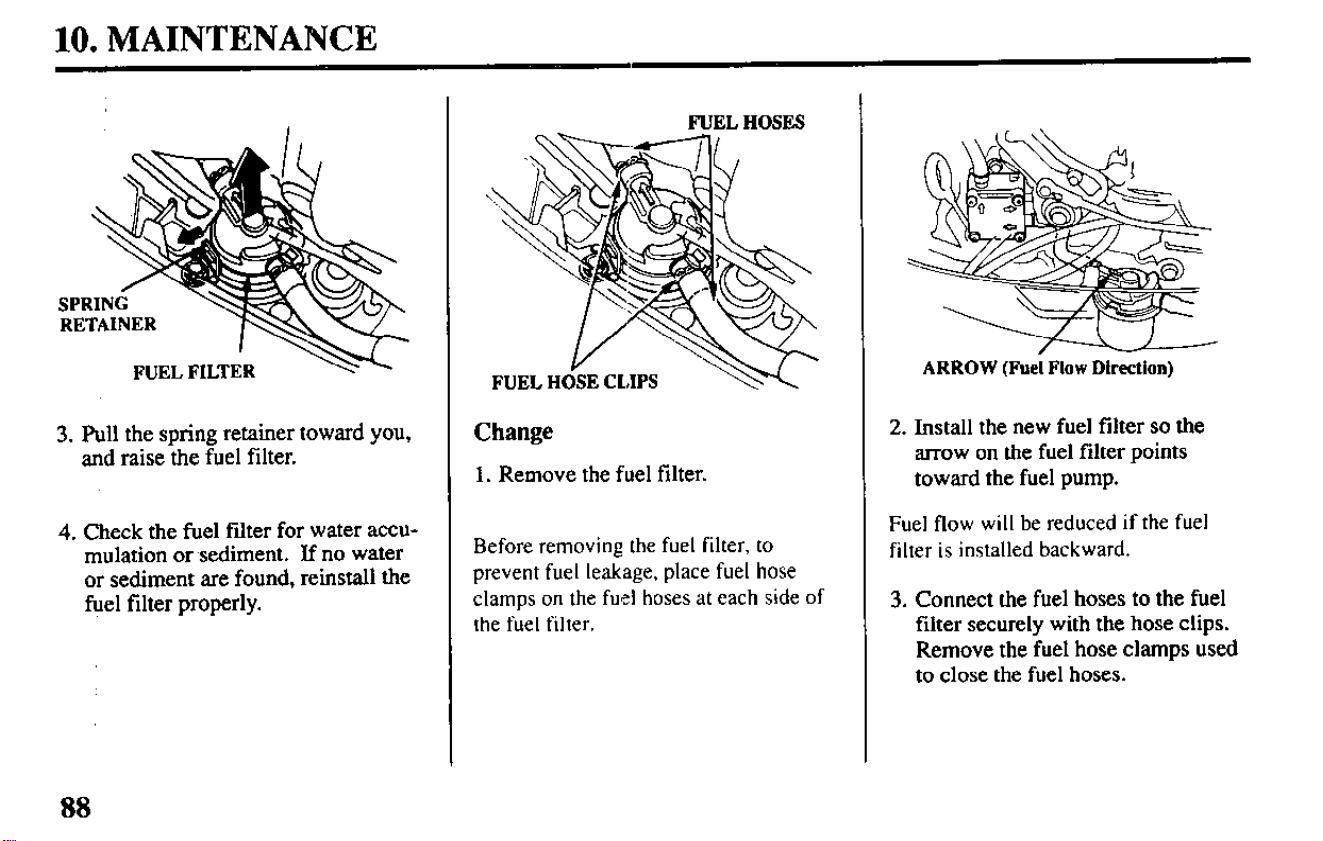
10. MAINTENANCE
3.
Pull the spring retainer toward you,
and raise the fuel filter.
4. Check the fuel filter for water accu-
mulation or sediment. If no water
or sediment are found, reinstall the
fuel filter properly.
FUEL HOSES
Change
1. Remove the fuel filter.
Before removing the fuel filter. to
prevent fuel leakage, place fuel hose
clamps on the fuel hoses at each side of
the fuel filter.
ARROW (Fuel Flow Direction)
2. Install the new fuel filter so the
arrow on the fuel filter points
toward the fuel pump.
Fuel flow will be reduced if the fuel
filter is installed backward.
3. Connect the fuel hoses to the fuel
filter securely with the hose clips.
Remove the fuel hose clamps used
to close the fuel hoses.
88
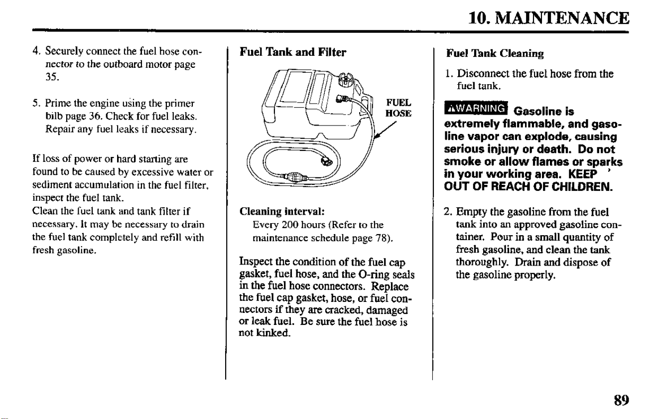
10. MAINTENANCE
4. Securely connect the fuel hose con-
nector to the outboard motor page
35.
5. Prime the engine using the primer
bilb page 36. Check for fuel leaks.
Repair any fuel leaks if necessary.
If loss of power or hard starting are
found to be caused by excessive water or
sediment accumulation in the fuel filter,
inspect the fuel tank.
Clean the fuel tank and tank filter if
necessary. It may be necessary to drain
the fuel tank completely and refill with
fresh gasoline.
Fuel Tank and Filter
Cleaning interval:
Every 200 hours (Refer to the
maintenance schedule page 78).
Inspect the condition of the fuel cap
gasket, fuel hose, and the O-ring seals
in the fuel hose connectors. Replace
the fuel cap gasket, hose, or fuel con-
nectors if they are cracked, damaged
or leak fuel. Be sure the fuel hose is
not kinked.
Fuel ‘Ihnk Cleaning
1. Disconnect the fuel hose from the
fuel tank.
extremely flammable, and gaso-
line vapor can explode, causing
serious injury or death. Do not
smoke or allow flames or sparks
in your working area. KEEP ’
OUT OF REACH OF CHILDREN.
2. Empty the gasoline from the fuel
tank into an approved gasoline con-
tainer. Pour in a small quantity of
fresh gasoline,
and
clean the tank
thoroughly. Drain and dispose of
the gasoline properly.
89
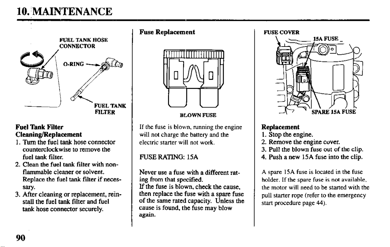
lO.:MAINTENANCE
FUEL TANK HOSE
CONNECTOR
FUEL TANK
FILTER
Fuel Tank Filter
Cleaning/Replacement
1.
Turn the fuel tank hose connector
counterclockwise to remove the
fuel tank filter.
2. Clean the fuel tank filter with non-
flammable cleaner or
solvent.
Replace the fuel tank filter if neces-
sary*
3. After cleaning or replacement, rein-
st$l the fuel tank filter and fuel
tank hose connector securely.
Fuse Replacement
BLOWN FUSE
If the fuse is blown, running the engine
will not charge the battery and the
electric starter will not work.
FUSE
RATING:
15A
Never use a fuse. with a different rat-
ing from that specified.
If the fuse is blown, check the cause,
then replace the fuse with a spare fuse
of the same rated capacity. Unless the
cause is found, the fuse may blow
again.
FUSE COVER
Replacement
1. Stop the engine.
2. Remove the engine cover.
3. Pull the blown fuse out of the clip.
4. Push a new 15A fuse into the clip.
A spare 15A fuse is located in the fuse
holder. If the spare fuse is not available,
the motor will need to be started with the
pull starter rope (refer to the emergency
start procedure page 44).
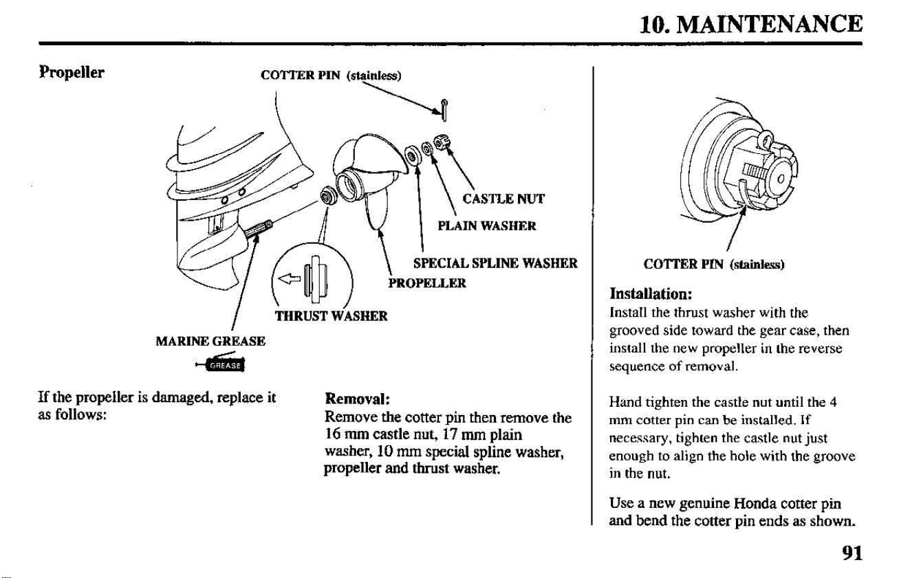
10. MAINTENANCE
Propeller
ECIAL SPLINE WASHER
PROPELLER
I
THRUST WASHER
MARINE GREASE
45i!i
If the propeller is damaged, replace it
as follows:
Removal:
Hand tighten the castle nut until the 4
Remove the cotter pin then remove the
16 mm castle nut, 17 mm plain
mm cotter pin can be installed. If
washer, 10 mm special spline washer,
necessary, tighten the castle nut just
propeller and thrust washer.
enough to align the hole with the groove
in the nut.
COTTER PIN (stainless)
Installation:
Install
the thrust washer with the
grooved side toward the gear case, then
install the new propeller in the reverse
sequence of removal.
Use a new genuine Honda cotter pin
and bend the cotter pin ends as shown.
91
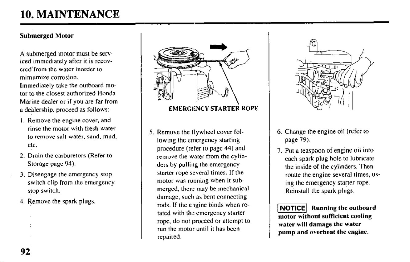
10. MAINTENANCE
Submerged Motor
A submerged motor must be serv-
iced immediately after it is recov-
ered’from the water inorder to
mimumize corrosion.
Immediately take the outboard mo-
tor to the closest authorized Honda
Marine dealer or if you are far from
a dehlership, proceed as follows:
I. Remove the engine cover, and
rinse the motor with fresh water
to remove salt water, sand, mud,
etc.
2. Drain the carburetors (Refer to
Storage page 94).
3. Disengage the emergency stop
switch clip from the emergency
stop switch.
4. Remove the spark plugs.
EMERGENCY STARTEli
ROPE
5.
Remove the flywheel cover fol-
lowing
the emergency starting
procedure (refer to page 44) and
remove the water from the cylin-
ders by pulling the emergency
starter rope several times. If the
motor was running when it sub-
merged, there may be mechanical
damage, such as bent connecting
rods. If the engine binds when ro-
tated with the emergency starter
rope, do not proceed or attempt to
run the motor until it has been
repaired.
6. Change the engine oil (refer to
page 79).
7. Put a teaspoon of engine oil into
each spark plug hole to lubricate
the inside of the cylinders. Then
rotate the engine several times, us-
ing the emergency starter rope.
Reinstall the spark plugs.
-1 Running the outboard
motor without suffkient cooling
water will damage the water
pump and overheat the engine.
92
10. MAINTENANCE
8. Engage the emergency stop
switch clip with the emergency
stop switch and attempt to start
the engine (be sure the water
level is at least 2 inches above the
anti-ventilation plate).
l If the engine fails to start, re-
move the spark plugs, clean
and dry the electrodes, then re-
install the spark plugs and at-
tempt to start the engine again.
l If the engine starts, and no me-
chanical damage is evident,
continue run the engine for a l/2
hour or longer.
l If there was water in the en-
gine crankcase, or the used en-
gine oil showed signs of water
contamination, then a second
engine oil change should be
performed after running the en-
gine for a l/2 hour.
9. Take the outboard motor to your
closest authorized Honda Marine
dealer for inspection and service
as soon as possible.
93
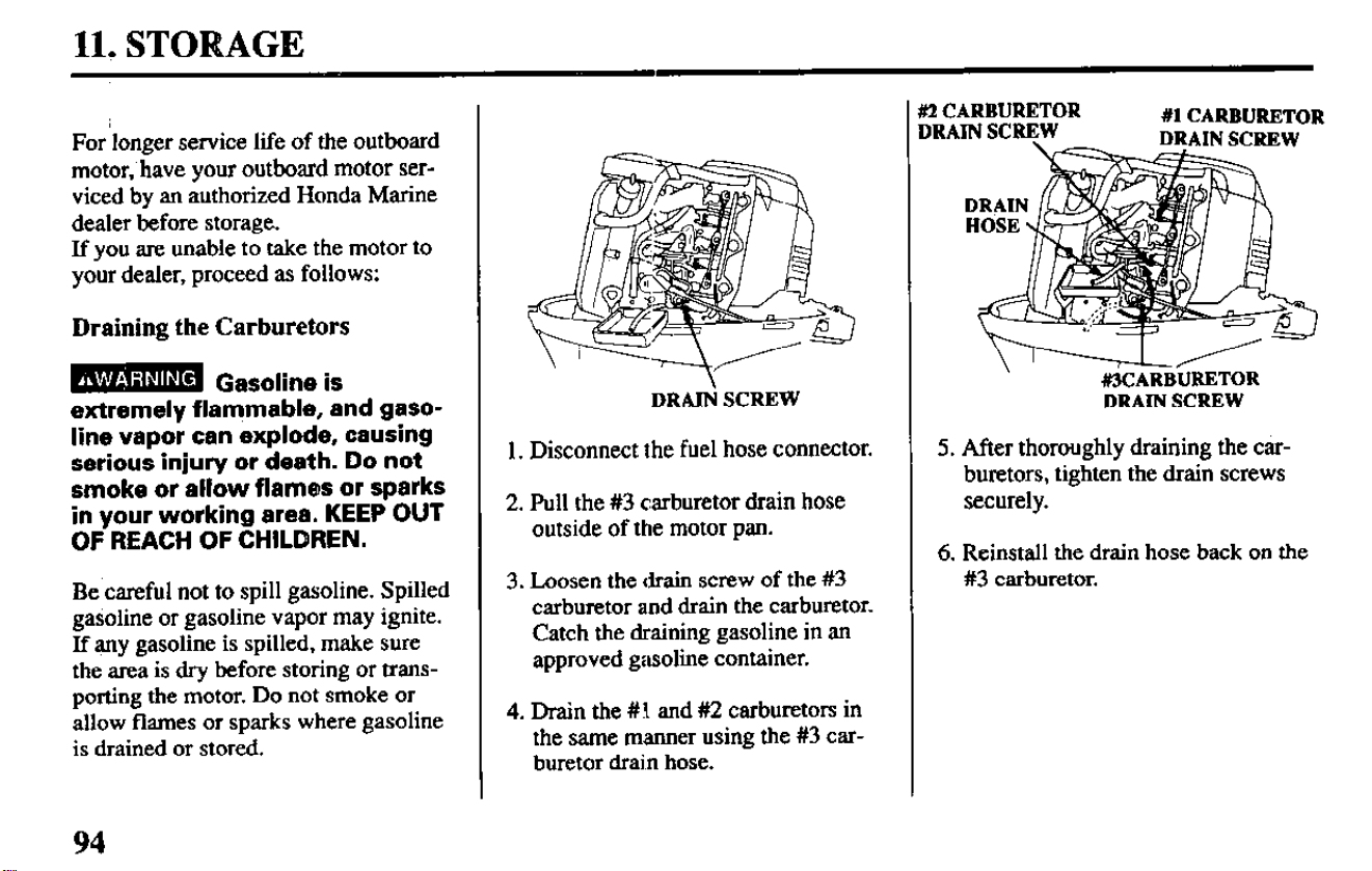
lit STORAGE
For longer service life of the outboard
motor,‘have your outboard motor ser-
viced by an authorized Honda Marine
dealer before storage.
If you are unable to take the motor to
your dealer, proceed as follows:
Draining the Carburetors
B Gasoline is
extremely flammable, and gaso-
line vapor can explode, causing
serious injury or death. Do not
smoke or allow flames or sparks
in your working area, KEEP OUT
OF REACH OF CHILDREN.
Be careful not to spill gasoline. Spilled
gasoline or gasoline vapor may ignite.
If any gasoline is spilled, make sure
the area is dry before storing or trans-
porting the motor. Do not smoke or
allow flames or sparks where gasoline
is drained or stored.
DRAII’i SCREW
1. Disconnect the fuel hose connector.
2. Pull the #3 carburetor drain hose
outside of the motor pan.
3. Loosen the drain screw of the #3
carburetor and drain the carburetor.
Catch the draining gasoline in an
approved gasoline container.
4. Dram the #I and #2 carburetors in
the same manner using the #3 car-
buretor dram hose.
DRA
tlos
KZCARBURETOR
#l CARBURETOR
#3CARBURETOR
DRAIN SCREW
5. After thoroughly draining the car-
buretors, tighten the drain screws
securely.
6. Reinstall the drain hose back on the
#3 carburetor.
94
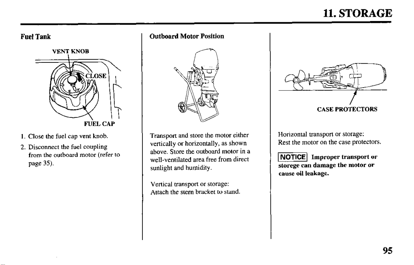
11. STORAGE
Fuel Tank
VENT KNOB
FUEL CAP
1. Close the fuel cap vent knob.
2. Disconnect the fuel coupling
from the outboard motor (refer to
page 35).
Outboard Motor Position
Transport and store the motor either
vertically or horizontally, as shown
above. Store the outboard motor in a
well-ventilated area free from direct
sunlight and humidity.
Vertical transport or storage:
Attach the stem bracket to stand.
CASE PROTECTORS
Horizontal transport or storage:
Rest the motor on the case protectors.
1 NOTICE 1 Improper transport or
storege can damage the motor or
cause oil leakage.
95
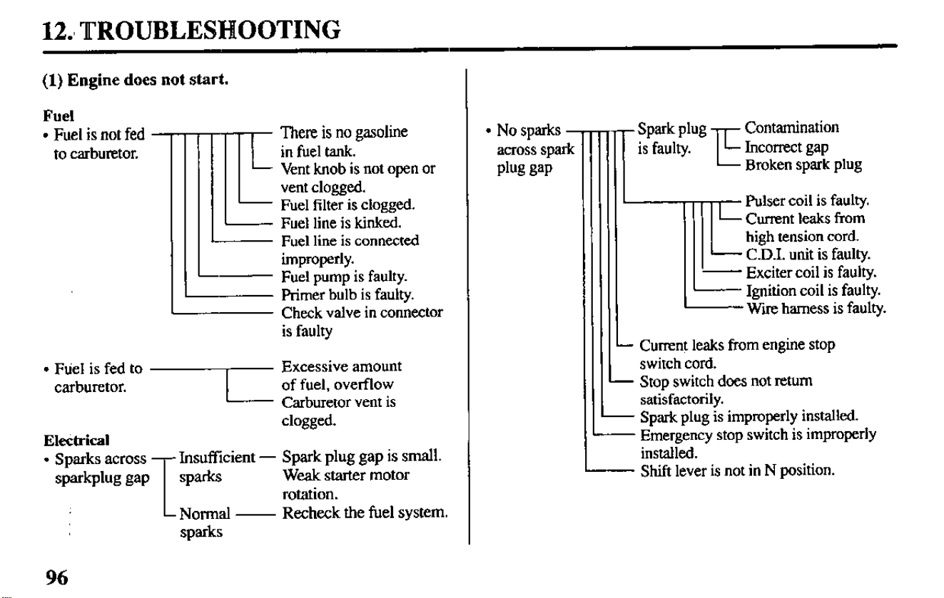
12.8 TROUBLESHOOTING
(1) Engine does not start.
Fuel
l
Fuel is not fed -
to carburetor.
II
There is no gasoline
in fuel tank.
Vent knob is not open or
vent clogged.
Fuel filter is clogged.
Fuel line is kinked.
Fuel line is connected
improperly.
Fuel pump is faulty.
primer bulb is faulty.
Check valve in connector
is faulty
clogged.
Electrical
l
Sparks across
T
Insufficient - Spark plug gap is small.
sparblw gap
sparks
Wcalc starter motor
rotation.
Normal -
Recheck the fuel system.
sparks
l
No sparks -
across spark
plug gap
Spark plug -,-,- Contamination
is faulty.
L
L- Incorrect gap
Broken spark plug
lTll
1
Fulser coil is faulty.
Current leaks from
high tension cord.
- C.D.I. unit is faulty.
I I ‘-
Exciter coil is faulty.
Ignition coil is faulty.
Wire harness is faulty.
Current leaks from engine stop
switch cord.
Stop switch does not return
satisfactorily.
- Spark plug is improperly installed.
- Emergency stop switch is improperly
installed.
Shift lever is not in N position.
96
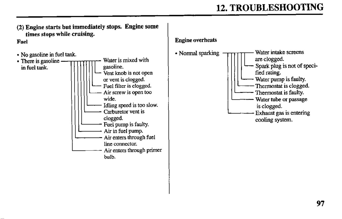
12. TROUBLESHOOTING
(2) Engine starts but immediately stops. Engine some
times stops while cruising.
Fuel
l
No gasoline in fuel tank.
l
There is gasoline -
in fuel tank.
iii
t
Water is mixed with
gasoline.
Vent knob is not open
or vent is clogged.
- Fuel filter is clogged.
I Air screw is open too
L
wide.
Idling speed is too slow.
- Carburetor vent is
clogged.
- Fuel pump is faulty.
Air in fuel pump.
Air enters through fuel
line connector.
Air enters through primer
bulb.
Engine overheats
l
Normal sparking
IE
Water intake screens
arc clogged.
Spark plug is not of speci-
fied rating.
Water pump is faulty.
Thermostat is clogged.
Thermostat is faulty.
Water tube or passage
is clogged.
Exhaust gas is entering
cooling system.
97
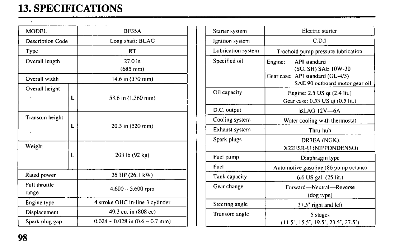
13. SPECIFICATIONS
MODEL
BF35A
Dtscription Code
Long shaft: BLAG
Type
RT
Overall length 27.0 in
(685 mm)
Overall width
14.6 in (370 mm)
Overall height
L
53.6 in ( 1,360 mm)
Transom height
L 20.5 in (520 mm)
Weight
L 203 lb (92 kg)
Rated power 35 HP (26. I kW)
Full throttle
range
4,600 - 5,600 ‘pm
Engine type
4 stroke OHC in-line 3 cylinder
Displacement
49.3 cu. in (808 cc)
Spark plug gap
0.024 - 0.028 in (0.6 - 0.7 mm)
(SC, SH) SAE low-30
98
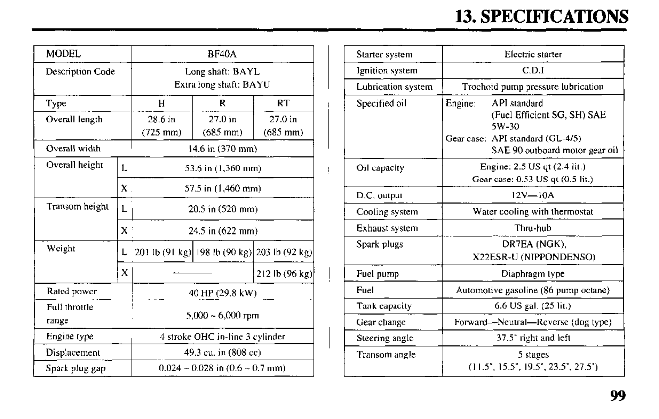
13. SPECIFICATIONS
MODEL
Description Code
Type
Overall length
BF40A
Long shaft: BAYL
Extra long shaft: BAYU
H
R RT
28.6 in 27.0 in 27.0 in
(725 mm) (685 mm) (685 mm)
Overall width
Overall height
Transom height
Weight
Rated power
14.6 in (370 mm)
L
53.6 in (1,360 mm)
X 57.5 in (1,460 mm)
L
20.5 in (520 mm)
X
24.5 in (622 mm)
L 201 lb (91 kg) 198 lb (90 kg) 203 lb (92 kg)
X
212 lb (96 kg)
40 HP (29.8 kW)
Full throttle
range
I
5,000 - 6,000 ‘pm
I
Engine type
4 stroke OHC in-line 3 cylinder
Displacement
49.3 cu. in (808 cc)
Spark plug gap 0.024 - 0.028 in (0.6 - 0.7 mm)
Starter system
Electric starter
Ignition system C.D.1
Lubrication system Trochoid pump pressure lubrication
Specified oil Engine: API standard
(Fuel Efficient SG, SH) SAE
5w-30
Oil capacity
D.C. output
Cooling system
Exhaust system
Spark plugs
Fuel pump
Fuel
Tank capacity
Gear change
Steering angle
Transom angle
Gear case: API standard (CL-415)
SAE 90 outboard motor gear oil
Engine: 2.5 US qt (2.4 lit.)
Gear case: 0.53 US qt (0.5 lit.)
l2V-IOA
Water cooling with thermostat
Thru-hub
DR7EA (NGK),
X22ESR-U (NIPPONDENSO)
Diaphragm type
Automotive gasoline (86 pump octane)
6.6 US gal. (25 lit.)
Forward-Neutral-Reverse (dog type)
37.5” right and left
5 stages
(I l.5”, 15.5”, 19.5”, 23.5”, 27.5”)
99
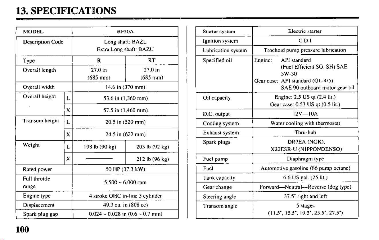
13. ,SPECHFICATIONS
Overall length
I
27.0 in
I
27.0 in
(685 mm) (685 mm)
I
Ov,erall width
I
14.6 in (370 mm)
I
Full throttle
range
I
5,500 - 6,000 rpm
Engine type
Disolacement
4 stroke OHC in-line 3 cylinder
49.3 cu. in (808 cc)
Spark plug gap 1
0.024 - 0.028 in (0.6 - 0.7 mm)
I
Starter system
I
Electric starter
I
Ignition system
I
C.D.1
I
Lubrication system
Trochoid pump pressure lubrication
Specified oil Engine:
API standard
(Fuel Efficient SG, SH) SAE
5w-30
Gear case: API standard (GL-415)
SAE 90 outboard motor gear oil
Oil capacity
I
Engine: 2.5 US qt (2.4 lit.)
Gear case: 0.53 US qt (0.5 lit.)
I
D.C. outout I 12V-IOA
I
Cooling system
Exhaust system
Water cooling with thermostat
Thru-hub
Spark plugs
DR7EA (NGK),
X22ESR-U (NIPPONDENSO)
Fuel pump
Fuel
Diaphragm type
Automotive gasoline (86 pump octane)
Tank capacity
I
6.6 US gal. (25 lit.)
I
Gear change
Steering angle
Forward-Neutral-Reverse (dog type)
37.5” right and left
Transom angle
5 stages
(I 1.5”, 15.5”. 19.5’. 23.5’. 27.5”)
J
100
14. WARRANTY SERVICE
Owner Satisfaction
Your satisfaction and good will are
important to your dealer and to us. All
Honda warranty details are explained
in the Distributor’s Limited Warranty.
Normally, any problems concerning
the product will be handled by your
dealer’s service department. If you
have a warranty problem that has not
been handled to your satisfaction, we
suggest you take the following action:
l
Discuss your problem with a mem-
ber of dealership management.
Often complaints can be quickly
resolved at that level. If the prob-
lem has already been reviewed with
the Service Manager, contact the
owner of the dealership or the
General Manager.
l
In order to contact the Honda
Marine Customer Service Office,
you can write to:
American Honda Motor Co., Inc.
Honda Power Equipment Division
Customer Service Office
4475 River Green Parkway
Duluth, GA 30136-2565
Or telephone: (404) 497-6400
We will need the following informa-
tion in order to assist you:
- Your name, address, and telephone
number
- Product model and serial number
- Date of purchase
- Dealer name and address
- Nature of the problem
Your purchase of a Honda product is
greatly appreciated by both your deal-
er and American Honda Motor Co.,
Inc. We want to assist you in every
way possible to assure your complete
satisfaction with your purchase.
101

Current customer service contact information:
Your owner's manual was written to cover most of the questions you might ask about
your Honda. Any questions not answered in the owner's manual can be answered by
your Honda dealer. If your dealer doesn't have an immediate answer, they should be
able to get it for you.
If you have a difference of opinion with your dealer, please remember that each
dealership is independently owned and operated. That's why it's important to work to
resolve any differences at the dealership level. If the service personnel are unable to
assist you, please discuss your concerns with the dealer management such as the
Service Manager or the dealership's owner.
If you need to contact American Honda regarding your experiences with your Honda
product or with your dealer, please send your comments to the following address:
American Honda Motor Co., Inc.
Marine Division
Customer Relations Office
4900 Marconi Drive
Alpharetta, GA 30005-8847
Or telephone: (770) 497-6400 M-F, 8:30 am - 7:00 pm EST
When you write or call, please provide the following information:
• Your name, address and telephone number (complete with area code)
• Model and complete serial number
• Date of purchase
• Name and location of the selling dealer
• Name and location of the servicing dealer (if different)
• A detailed description of your concerns
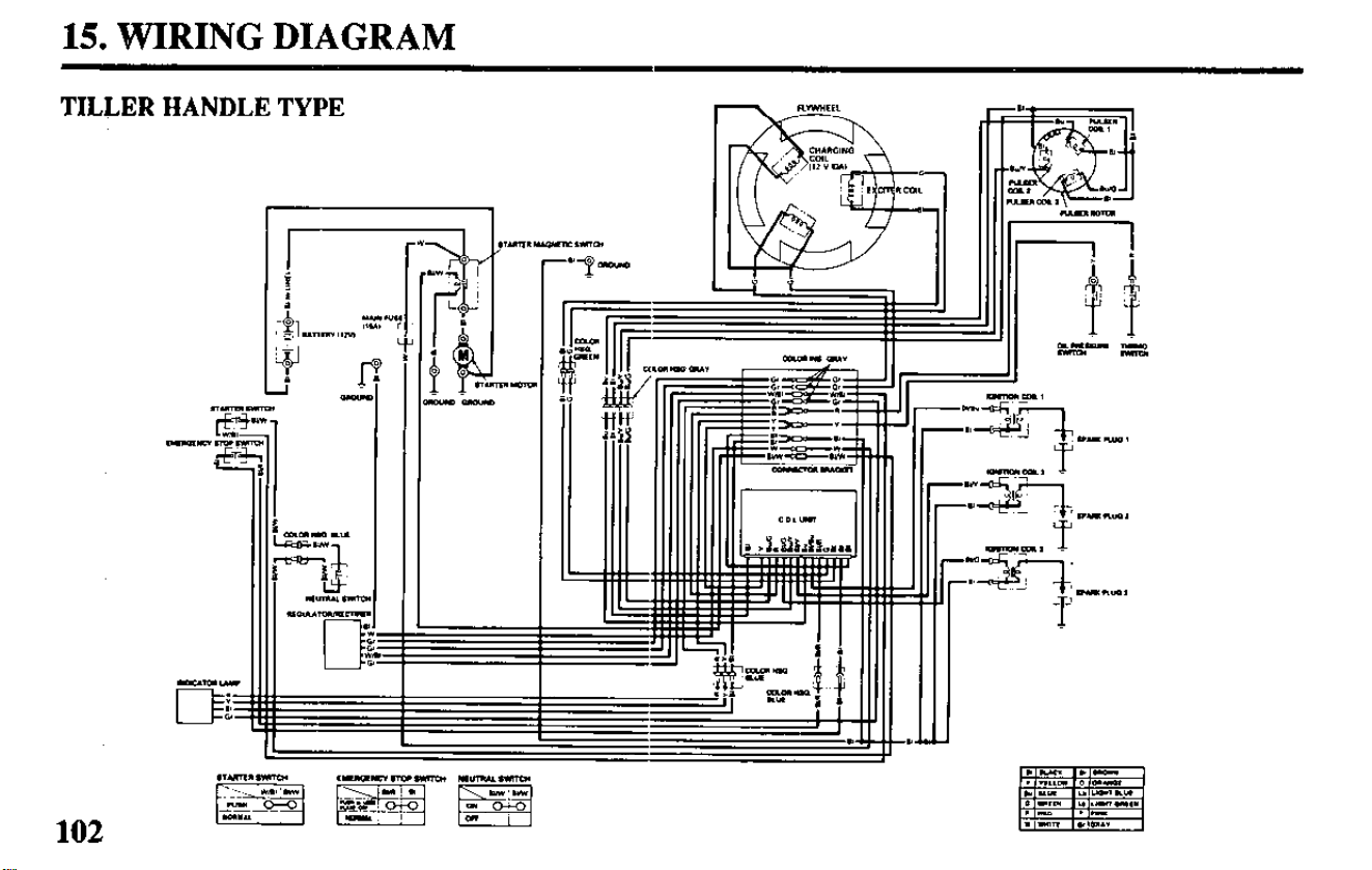
15. WIRING DIAGRAM
TILLER HANDLE TYPE
fp
9
*
I
:
L -
n- DITm
D
102
t
=
-
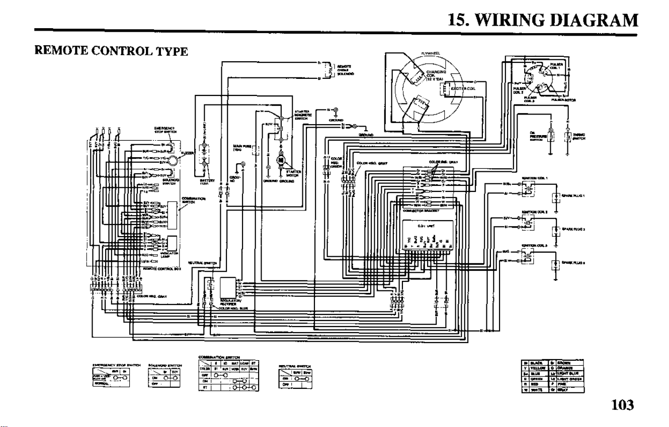
15. WIRING DIAGRAM
REMOTE CONTROL TYPE
F==
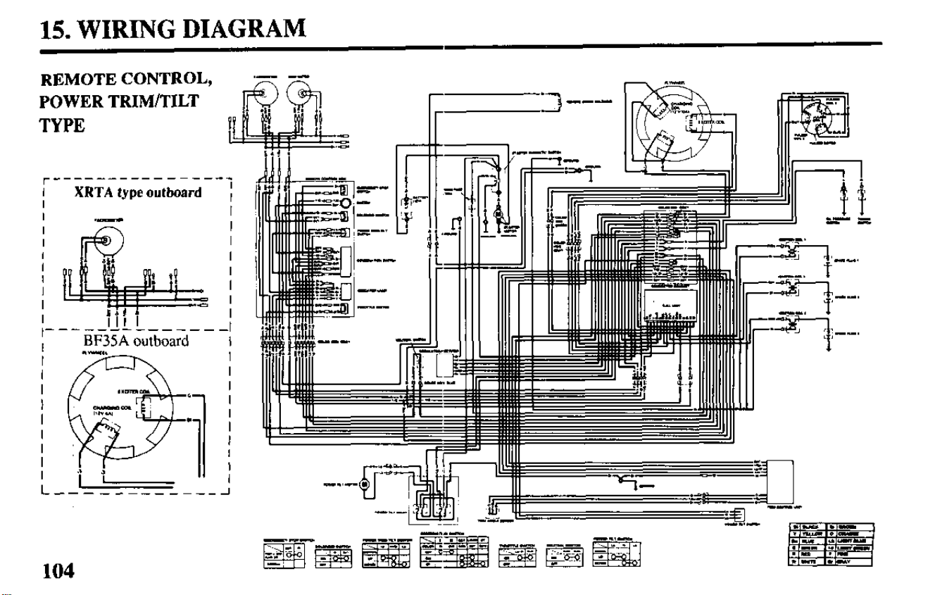
15. WIRING DIAGRAM
r---------------’
I
XRTA type outboard
I
I
I
REMOTE
CONTROL,
POWER TRIM/TILT
TYPE
*= ;
HP I
-------------_
BF35A outboard I
104
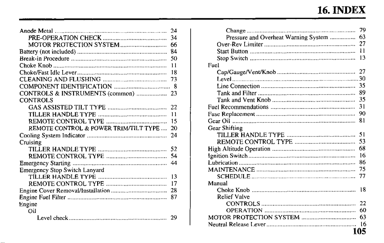
16. INDEX
Anode Metal ...................................................................... 24
PRE-OPERATION CHECK ........................................ 34
MOTOR PROTECTION SYSTEM.. ........................... 66
Battery (not included) ........................................................ 84
Break-in Procedure ............................................................ 50
Choke Knob ....................................................................... 1 1
Choke/Fast Idle Lever.. ...................................................... 18
CLEANING AND FLUSHING ........................................ 73
COMPONENT IDENTIFICATION ................................... 8
CONTROLS & INSTRUMENTS (common) ................... 23
CONTROLS
GAS ASSISTED TILT TYPE ..................................... 22
TILLER HANDLE TYPE ........................................... 1 1
REMOTE CONTROL TYPE ...................................... 15
REMOTE CONTROL & POWER TRIM/TILT TYPE.. .. 20
Cooling System Indicator
..................................................
24
Cruising
TILLER HANDLE TYPE ........................................... 52
REMOTE CONTROL TYPE ......................................
54
Emergency Starting ........................................................... 44
Emergency Stop Switch Lanyard
TILLER HANDLE TYPE ........................................... 13
REMOTE CONTROL TYPE
......................................
17
Engine Cover Removal/Installation
...................................
28
Engine Fuel Filter .............................................................. 87
Engine
Oil
Level check..
...........................................................
29
Change
....................................................................
79
Pressure and Overheat Warning System ................ 63
Over-Rev Limiter
.........................................................
27
Start Button ..................................................................
1 1
Stop Switch ..................................................................
13
Fuel
Cap/Gauge/Vent/Knob
.................................................
27
Level
..............................................................................
.30
Line Connection ...........................................................
35
Tank and Filter .............................................................
89
Tank and Vent Knob
....................................................
35
Fuel Recommendations .....................................................
3 1
Fuse Replacement
..............................................................
90
Gear Oil
.............................................................................
81
Gear Shifting
TILLER HANDLE TYPE ...........................................
5 1
REMOTE CONTROL TYPE
...................................... 53
High Altitude Operation ....................................................
68
Ignition Switch
................................................................... 16
Lubrication .........................................................................
86
MAINTENANCE
..............................................................
75
SCHEDULE
......... ........................................................
77
Manual
Choke Knob .................................................................
18
Relief Valve
CONTROLS ........................................................... 22
OPERATION ......................................................... 60
MOTOR PROTECTION SYSTEM
.................................. 63
Neutral Release Lever
.......................................................
.
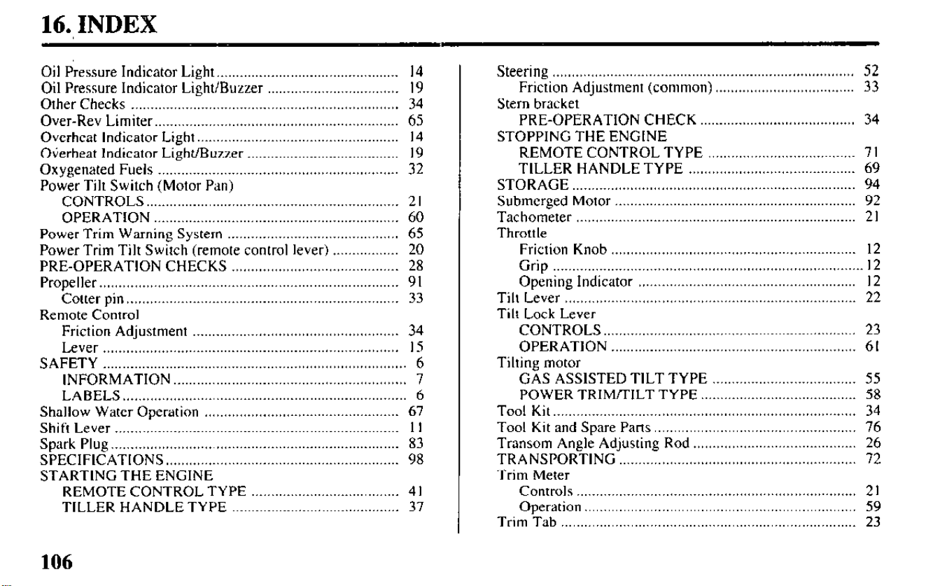
16., INDEX
Oil Pressure Indicator Light..
............................................. 14
Oil Pressure Indicator Light/Buzzer
..................................
19
Other Checks .....................................................................
34
Over-Rev Limiter.. .............................................................
65
Overheat Indicator Light..
..................................................
14
Overheat Indicator Light/Buzzer
.......................................
19
Oxygenated Fuels
..............................................................
32
Power Tilt Switch (Motor Pan)
CONTROLS..
............................................................... 2 I
OPERATION ...............................................................
60
Power Trim Warning System
............................................
65
Power Trim Tilt Switch (remote control lever)
................. 20
PRE-OPERATION CHECKS
...........................................
28
Propeller..
...........................................................................
9 I
Cotter pin.. ....................................................................
33
Remote Control
Friction Adjustment
.....................................................
34
Lever
............................................................................
15
SAFETY
.............................................................................. 6
INFORMATION..
.......................................................... 7
LABELS..
....................................................................... 6
Shallow Water Operation
..................................................
67
Shift Lever
.........................................................................
II
Spark Plug..
........................................................................ 83
SPECIFICATIONS..
.......................................................... 98
STARTING THE ENGINE
REMOTE CONTROL TYPE
......................................
4 I
TILLER HANDLE TYPE
........................................... 37
Steering
..............................................................................
52
Friction
Adjustment (common) .................................... 33
Stern bracket
PRE-OPERATION
CHECK ........................................ 34
STOPPING THE ENGINE
REMOTE CONTROL TYPE
...................................... 7 I
TILLER
HANDLE TYPE ........................................... 69
STORAGE
.........................................................................
94
Submerged
Motor .............................................................. 92
Tachometer
........................................................................ 2 I
Throttle
Friction Knob
...............................................................
12
Grip
................................................................................ 12
Opening
Indicator ........................................................ 12
Tilt Lever
........................................................................... 22
Tilt Lock Lever
CONTROLS..
............................................................... 23
OPERATION
............................................................... 6 I
Tilting motor
GAS
ASSISTED TILT TYPE ..................................... 55
POWER
TRIM/TILT TYPE.. ...................................... 58
Tool Kit..
............................................................................ 34
Tool Kit and Spare
Parts .................................................... 76
Transom Angle Adjusting
Rod .......................................... 26
TRANSPORTING
............................................................. 72
Trim Meter
Controls
........................................................................ 2 I
Operation..
.................................................................... 59
Trim Tab
............................................................................ 23
106
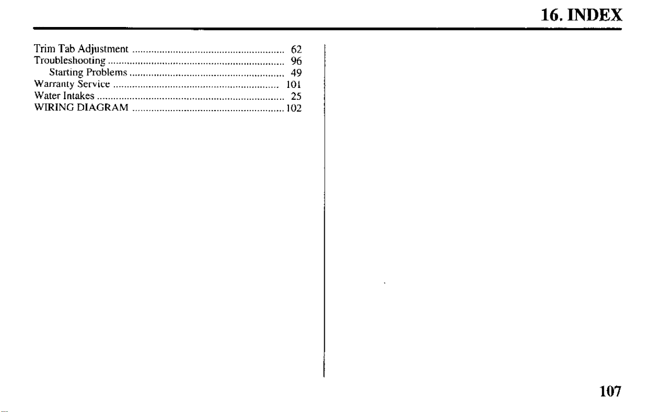
16. INDEX
Trim
Tab Adjustment . . . . . . . . . . . . . . . . . . . . . . . . . . . . . . . . . . . . . . . . . . . . . . . . . . . . . . . . 62
Troubleshooting
. . . . . . . . . . . . . . . . . . . . . . . . . . . . . . . . . . . . . . . . . . . . . . . . . . . . . . . . . . . . . . . . .
96
Starting Problems . . . . . . . . . . . . . . . . . . . . . . . . . . . . . . . . . . . . . . . . . . . . . . . . . . . . . . . . .
49
Warranty
Service . . . . . . . . . . . . . . . . . . . . . . . . . . . . . . . . . . . . . . . . . . . . . . . . . . . . . . . . . . . . . 10 1
Water Intakes
. . . . . . . . . . . . . . . . . . . . . . . . . . . . . . . . . . . . . . . . . . . . . . . . . . . . . . . . . . . . . . . . . . . . . 25
WIRING
DIAGRAM . . . . . . . . . . . . . . . . . . . . . . . . . . . . . . . . . . . . . . . . . . . . . . . . . . . . . . . . 102
107