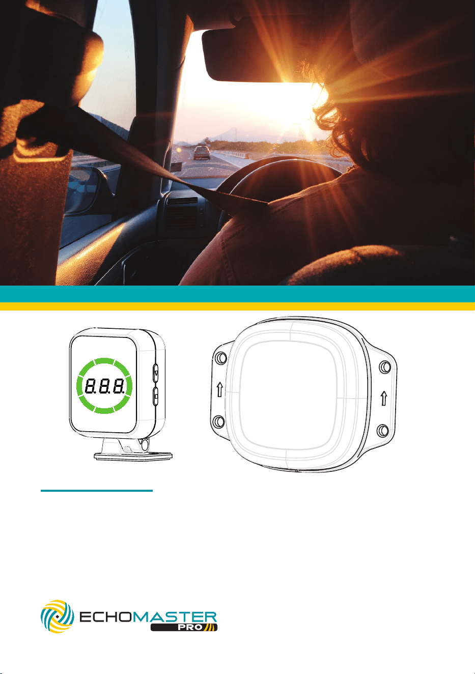
77GHz Blind Spot Detection Assist System
OPERATION GUIDE / MANUAL
PBS-RD1

2
email - [email protected]
tel - 727-592-5991
Thank you for purchasing the
EchoMaster
PBS-RD1
The EchoMaster Pro radar detection system is designed to assist
in the avoidance of obstacles while reversing and driving.
Disclaimer:
EchoMaster® is strictly a driver assistance device, and should not be relied upon
as a substitute for safe driving practices. Use common sense when parking and
always follow recommended safe driving guidelines from your local, State and
County Department of Motor Vehicles regarding parking procedures. To help pre-
vent accidents, always use caution when parking, looking visually to ensure your
path is clear. Keep speeds under three miles per hour. The owner shall not be
entitled to recover from the Company, its successors or assignees, incidental and
consequential damages, such as personal injury, loss of income, loss of time, loss
of profits, loss of vehicle use or property damage.
No employee, agent or representative of the Company of the Selling Retailer may
modify, alter or extend this Warranty in any way. This Warranty gives you specific
legal rights. You may also have other rights under this Warranty which may vary
from state to state.
Note: Under no circumstances should you attempt to open the control box or any
other component. Doing so will void all manufacturer’s warranties.
3
email - [email protected]
tel - 727-592-5991
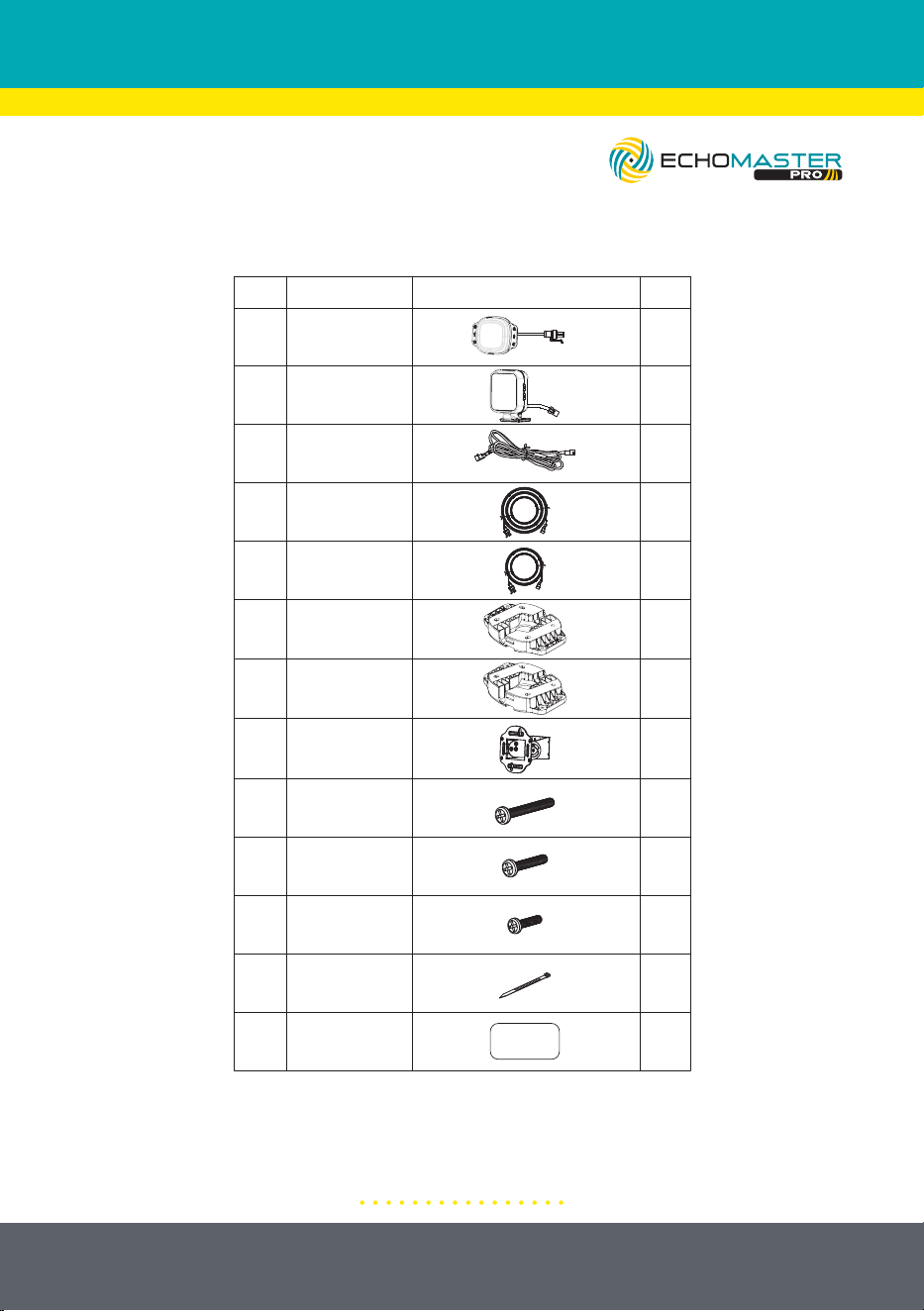
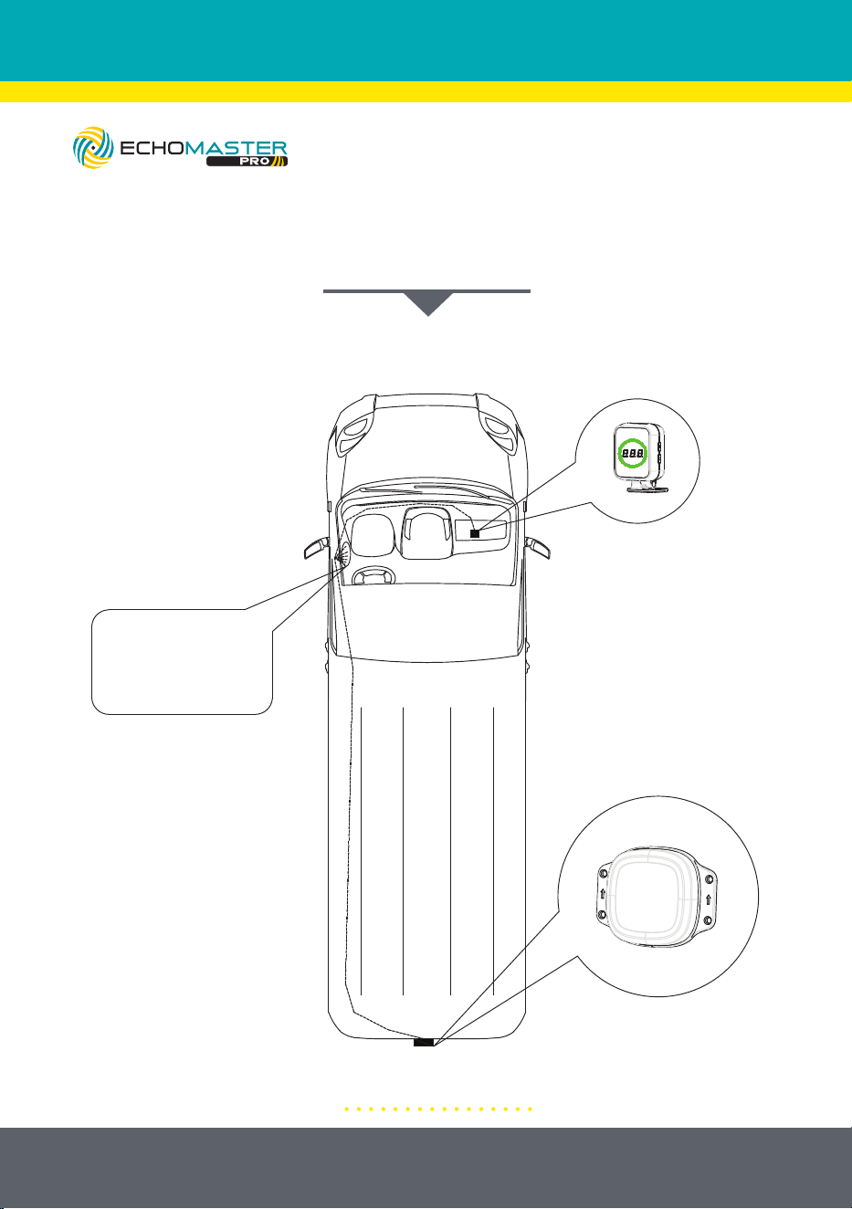
SYSTEM COMPONENTS
1. System Components
No.
Name
Diagram
Display
1
2
3
4
Main Harness
32.8’ (10m)
Sensor
Extension
Sensor
16.4’ (5m)
Sensor
Extension
Qty
1
1
1
1
1
5
8
9
10
Sensor
Bracket
11
Screw
4.8*30mm
Screw
5*20mm
Screw
4*15mm
Cable Tie
QR Card
12
13
1
4
8
2
10
1
5˚ Angled
Sensor
Mounting Plate
10˚ Angled
Sensor
Mounting Plate
1
1
6
7
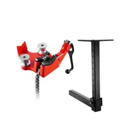
RD1-HITCH-BRK Optional Trailer Hitch Mount
Instructions see page 22
4
email - [email protected]
tel - 727-592-5991
Illustrations are typical and may not match exact vehicle detail
Blind Spot Detection Assist System
INSTALLATION GUIDE
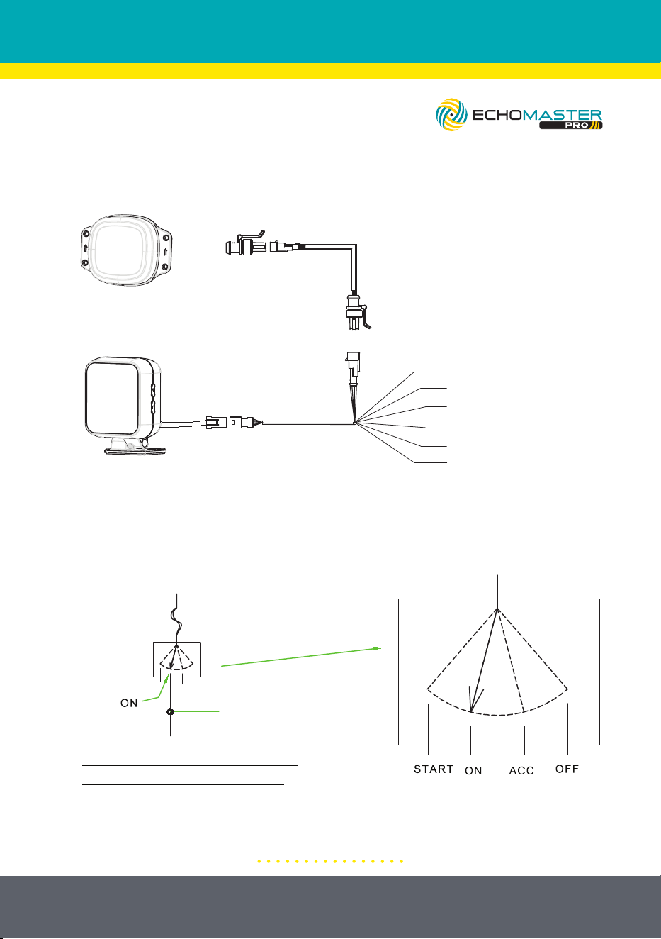
SYSTEM WIRING DIAGRAM
3. System Wiring Diagram
GND (Black)
IGN/ACC (Red)
Reverse Signal Wire (Purple)
Right Turn Signal Wire (Gray)
Left Turn Signal Wire (White)
Trigger Output (Green)
5
email - [email protected]
tel - 727-592-5991
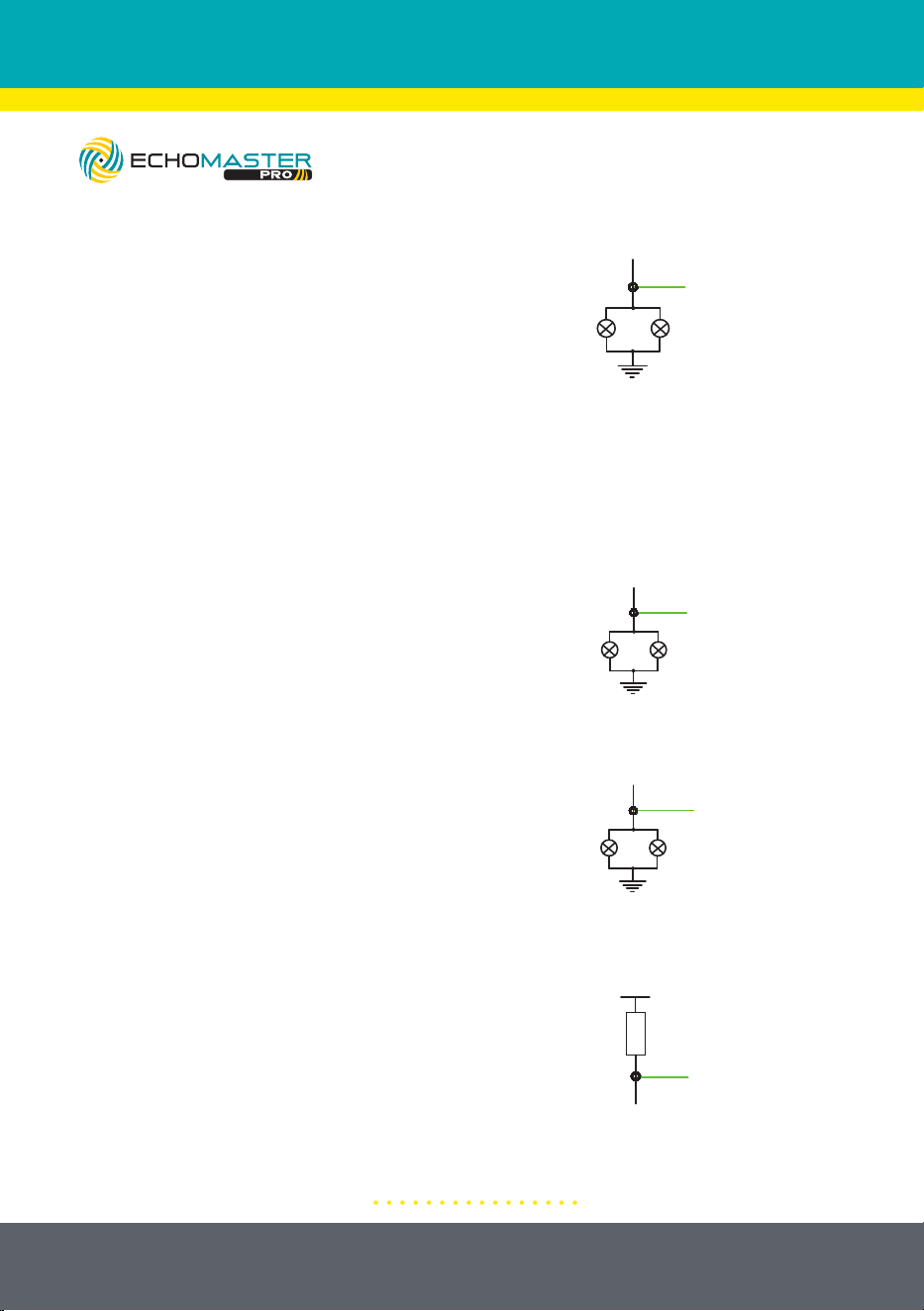
1: Connect Ignition Power Wire (+)
SYSTEM CONNECTION OVERVIEW
4.Connect Left Turn Signal Wire (+)
1. Connect Ignition Power Wire (+)
3. Connect Ground (-)
2. Connect Reverse Signal Wire (+)
Sensor
Display
GND (Black)
IGN/ACC (Red)
Reverse Signal Wire (Purple)
Right Turn Signal Wire (Gray)
Left Turn Signal Wire (White)
Trigger Output (Green)
6. Connect Trigger Output Wire (-)
Note: Optional Connection
5.Connect Right Turn Signal Wire (+)
Reverse
Signal
connect reverse
signal wire here
GND
GND
Left
Turn
Signal
connect left
turn signal
wire here
connect trigger
wire here
VCC
Load
connect right
turn signal
wire here
GND
Right
Turn
Signal
Connect the ground
ring terminal (black wire)
to chassis ground.
Note: the system will be on when the
vehicle’s ignition is turned to "ON".
Ignition
Switch
Battery +
Fuse
connect power
wire here
Ignition
Circuit
6
email - [email protected]
tel - 727-592-5991
Connect the ground ring terminal
(black wire) to chassis ground.
2: Connect Reverse Signal Wire (+)
3: Connect Ground (-)
4: Connect Left Turn Signal Wire (+)
5: Connect Right Turn Signal Wire (+)
6: Connect Trigger Output Wire (-)
Note: Optional Connection
4.Connect Left Turn Signal Wire (+)
1. Connect Ignition Power Wire (+)
3. Connect Ground (-)
2. Connect Reverse Signal Wire (+)
Sensor
Display
GND (Black)
IGN/ACC (Red)
Reverse Signal Wire (Purple)
Right Turn Signal Wire (Gray)
Left Turn Signal Wire (White)
Trigger Output (Green)
6. Connect Trigger Output Wire (-)
Note: Optional Connection
5.Connect Right Turn Signal Wire (+)
Reverse
Signal
connect reverse
signal wire here
GND
GND
Left
Turn
Signal
connect left
turn signal
wire here
connect trigger
wire here
VCC
Load
connect right
turn signal
wire here
GND
Right
Turn
Signal
Connect the ground
ring terminal (black wire)
to chassis ground.
Note: the system will be on when the
vehicle’s ignition is turned to "ON".
Ignition
Switch
Battery +
Fuse
connect power
wire here
Ignition
Circuit
7
email - [email protected]
tel - 727-592-5991
Illustrations are typical and may not match exact vehicle detail
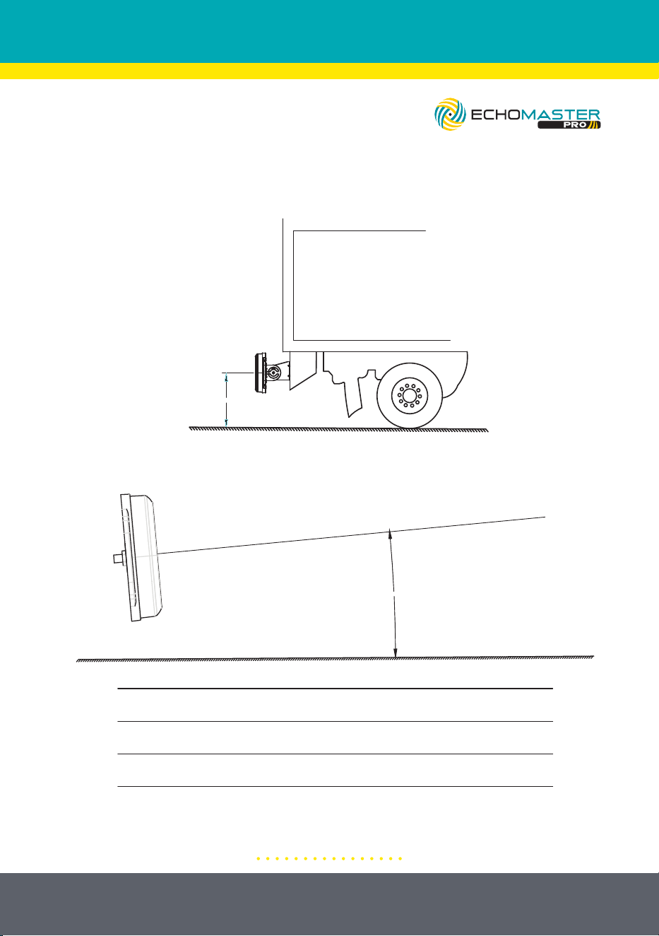
SENSOR INSTALLATION
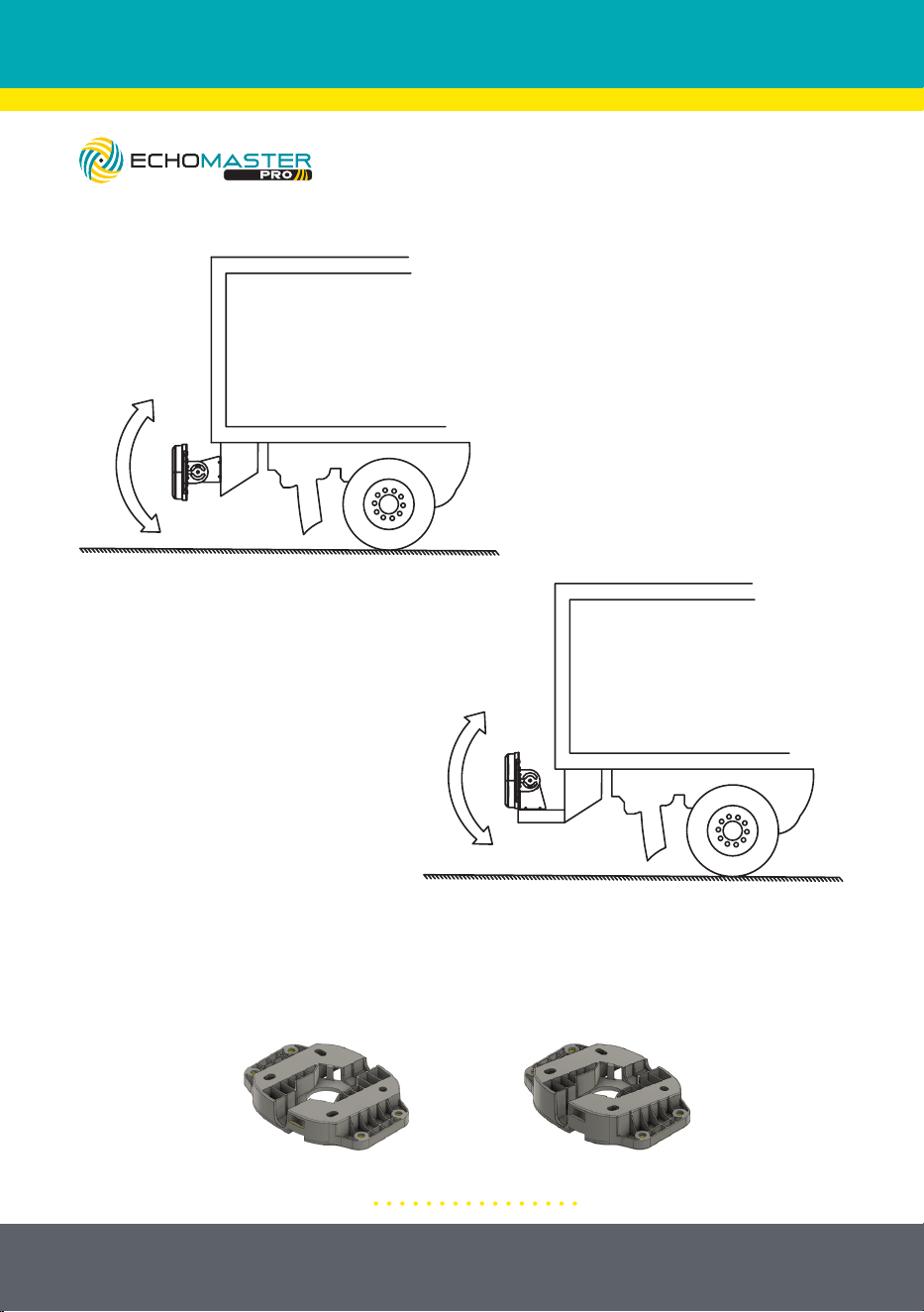
1: Installation Height Requirement
2: Vertical Angle Requirement
4. Sensor Installation
(1) Installation height requirement
(2) Vertical angle requirement
Installation height Upward tilt angle
23.6”-29.5” (0.6-0.75m) 10°
29.5”-51.2” (0.75-1.3m) 5°
Upward angle
(3) Sensor fixation
A. The sensor bracket is fixed on a horizontal
plane and the vertical installation angle is
adjusted through the installation bracket
B. The sensor bracket is fixed on a
vertical surface and the vertical
installation angle is adjusted through the
installation bracket.
23.6”-51.2”
(0.6-1.3m)
8
email - [email protected]
tel - 727-592-5991
Illustrations are typical and may not match exact vehicle detail
3: Sensor and Bracket Orientation
A. The sensor bracket is fixed on
a horizontal plane and the vertical
installation angle is adjusted
through the installation bracket.
B. The sensor bracket is fixed on
a vertical plane and the vertical
angle is adjusted through the
installation bracket.
4. Sensor Mounting Without Bracket
For flush mounting applications where the sensor will be mounted directly to
the vehicle body. Use the included 5° or 10° angled mounting plate based on
installation height of the sensor.
9
email - [email protected]
tel - 727-592-5991
Illustrations are typical and may not match exact vehicle detail
DISPLAY INSTALLATION
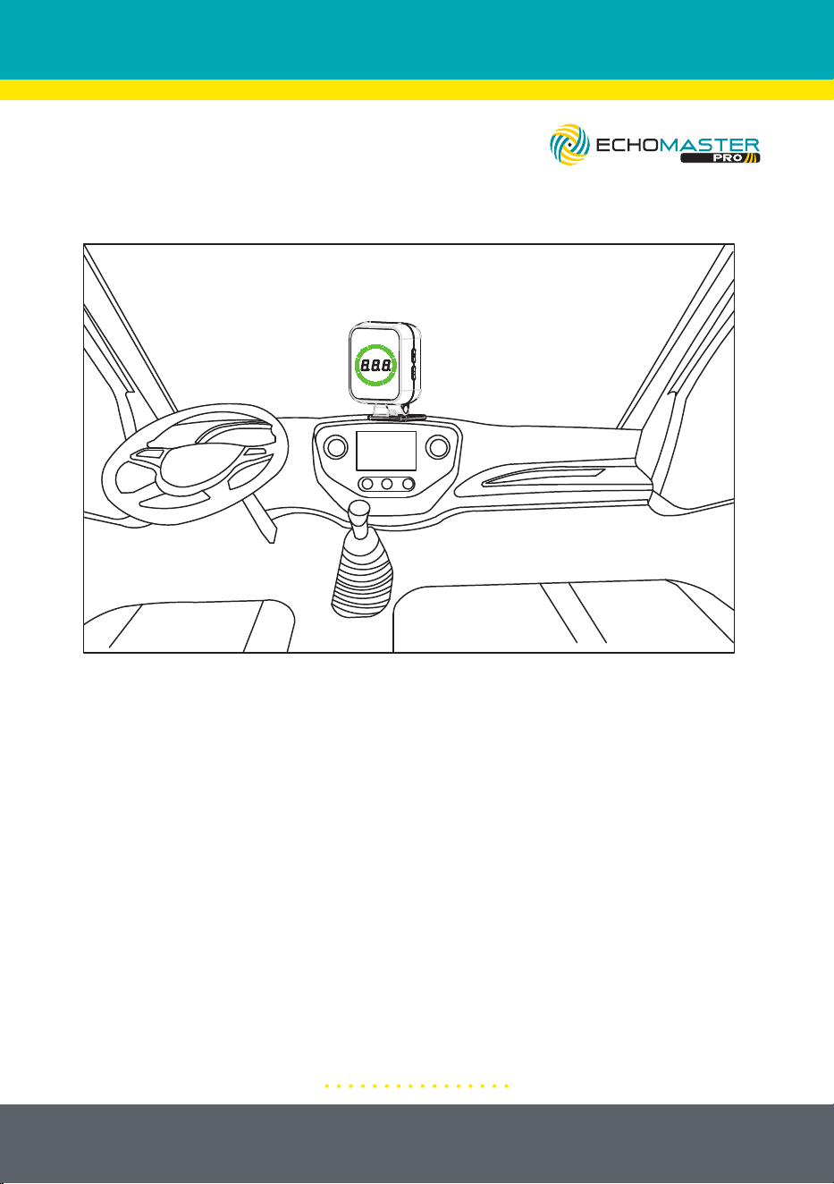
5. Display Installation
(1) Select location: Choose a suitable location so that the driver can easily observe the content
displayed on the monitor
(2) Monitor fixation: Clean the adhesive position of the monitor, remove the 3M
adhesive from the bottom of the monitor, and stick it in a suitable position. It can also
be fixed with screws.
6. Technical Parameters
DC 9-16V
<350mA@12V
-40˚ F-176˚ F
-40˚ F-176˚ F
77-81GHz
FMCW
30°
150°
2TX,4RX
Operating Voltage
Current Consumption
Working Temperature
Storage Temperature
Frequency
Modulation Mode
Vertical Angle
Horizontal Angle
Antenna Type
1: Select Location
Choose a suitable mounting location that the driver can easily observe the
content on the display.
2: Display Mounting
Clean the mounting location with an alcohol swab or similar. Remove the 3M
adhesive backing and adhere the display mount to the dash or other chosen
location. Alternatively, screws can be used to mount the display in place.
Automatic Brightness Adjustment
The display detects the external brightness and will automatically adjust the
brightness of the display.
10
email - [email protected]
tel - 727-592-5991
FUNCTION DESCRIPTION
7. Function Description
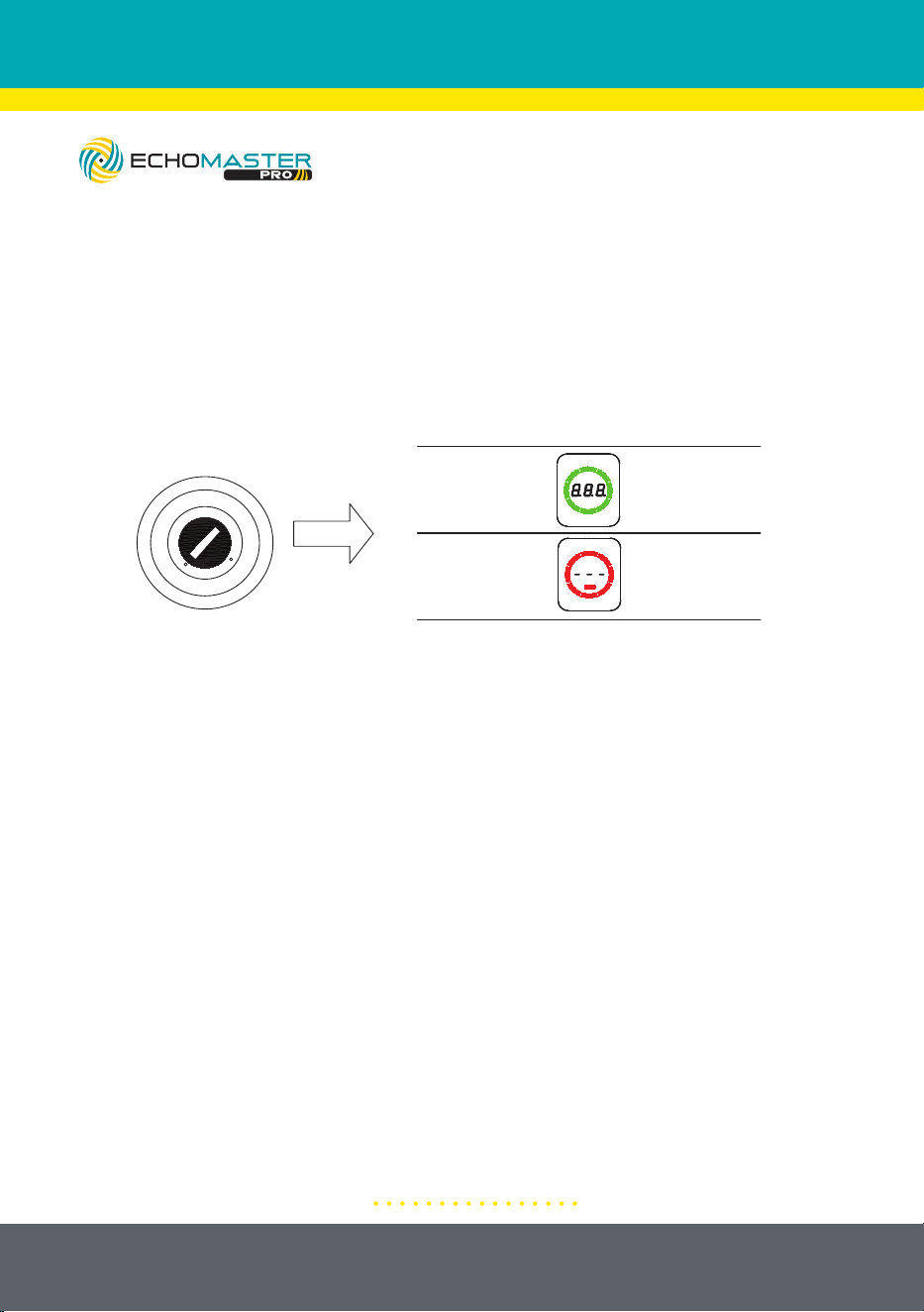
(1) Self-Diagnosis
When the key is turned to ON, the system starts to make self-diagnosis, and remind driver of the
system status by audible and visible warning.
LOCK
ACC
ON
START
System
Status
Display
Reading
Sound Cue
Normal
Operation
Beep once
(Bi--)
Sensor
Abnormality
Beep twice
(Bi-Bi-)
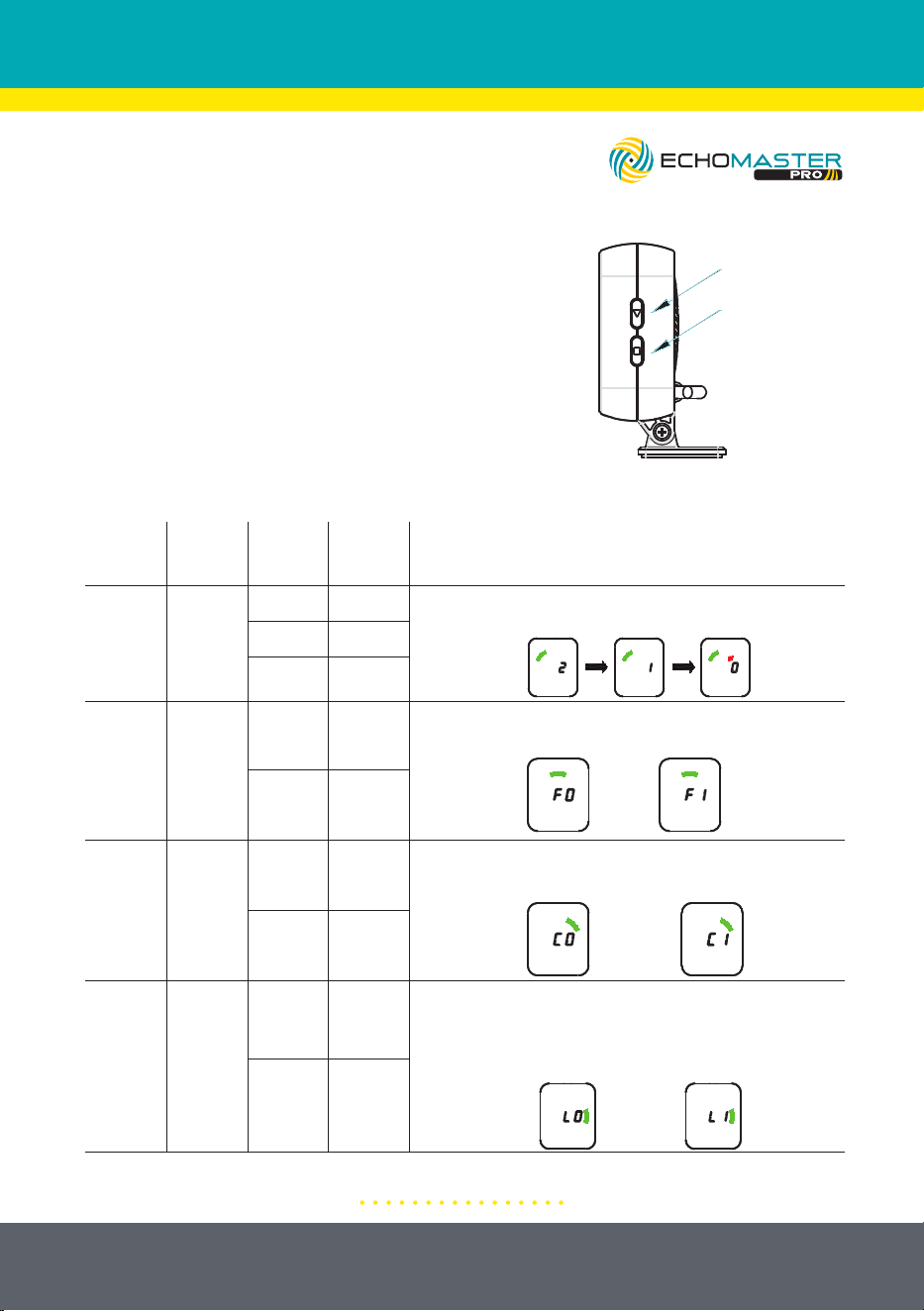
(2) System Settings
Press the select button to select the settings function, and press the confirm button to enter the
settings for this function.
Setting
Function
Function
Selection -
Button
Count
Setting
Functions
Display
Reading
Define Notes
1 Time
Volume
Setting
No
Sound
Press □ button once, the buzzer will beep once to enter volume
adjustment mode. Press the ▽ setting button, the volume will
cycle through 2, 1, and 0, and stop pressing to automatically
save and exit.
Low
Output
High
Output
2 Times
Standard
Settings
(Distance
Reading)
F0
Metric
System
Press the □ button twice, the buzzer will beep once to enter the
display standard setting mode. Press the ▽ setting key, cycle
through F0 and F1 modes, and stop pressing to automatically save
and exit.
F1
Imperial
System
3 Times
Target Type
Setup
C0
All targets
detected
Press the □ button three times, and the buzzer will sound once
to enter the target detection setting mode. Press the ▽ setting
button, cycle through C0 and C1 modes, and stop pressing to
automatically save and exit.
C1
Only detect
moving
targets
4 Times
Sensor
Learning
Function
Setup
(Refer to
page 13
for more
detail)
L0
Not
Learning
Press the □ button four times, the buzzer will beep once to
enter the learning setting mode. Press the ▽ setting button
once, and the display will display "L1". The system will enter
the learning mode, and the green bars will light up one by one in
a circle during the learning process. After successful learning,
"L5" will be displayed and keep ringing for one second.
L1
Automatic
Learning
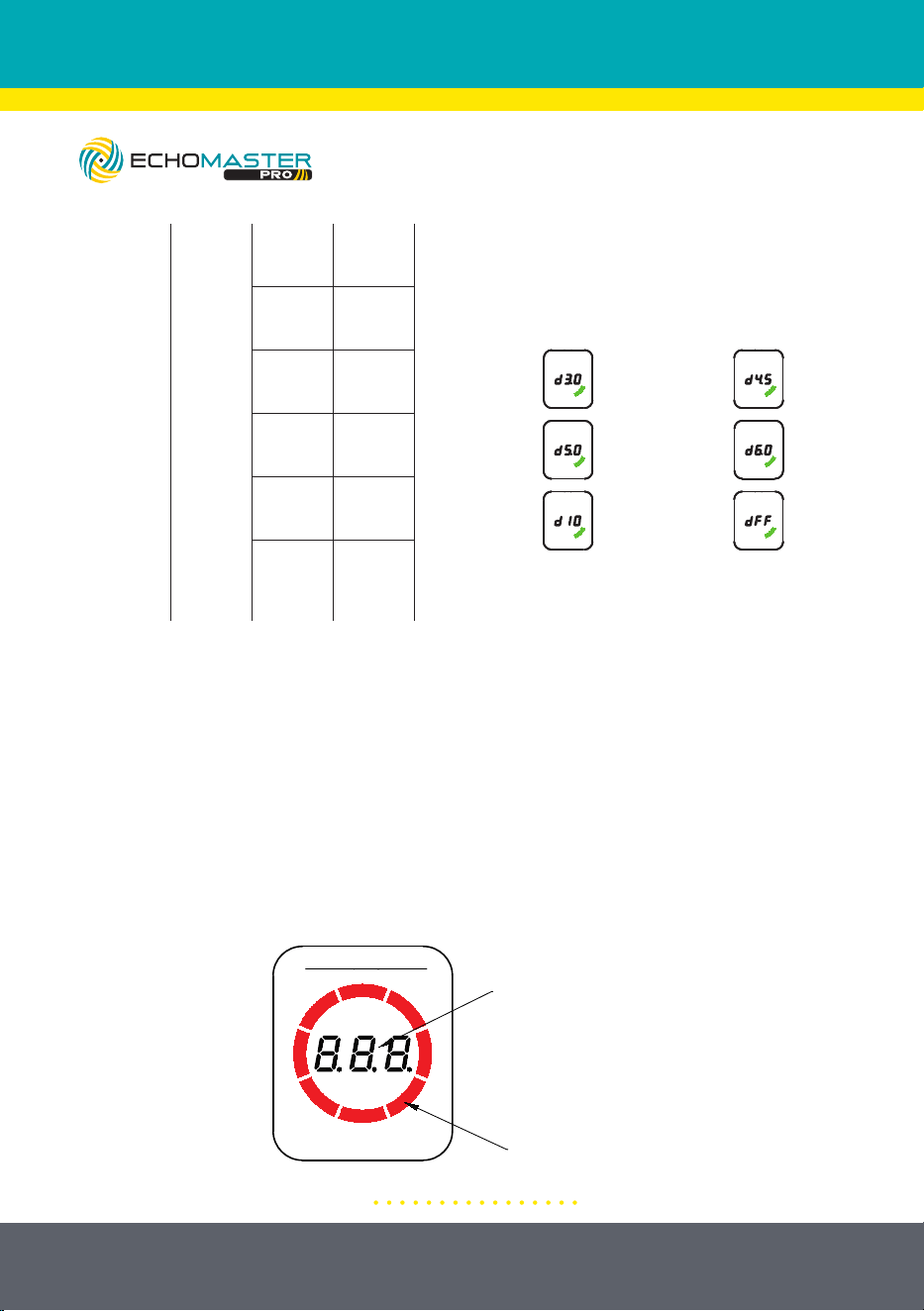
5 Times
Detection
Range
Setting
d3.0
Detection
Range =
9.8’*7.9’
(3.0m*2.4m)
Press the □ button five times, and the buzzer will sound once to
enter the detection distance setting mode. Press the ▽ setting
button once, and the mode will cycle through d3.0, d4.5, d5.0,
d6.0, d10, and dFF. Stop pressing and automatically save and
exit.
d4.5
Detection
Range =
14.8’ * 11.2’
(4.5m * 3.4m)
d5.0
Detection
Range =
16.4’ * 13.1’
(5.0m * 4.0m)
d6.0
Detection
Range =
19.7’ * 14.4’
(6.0m * 4.4m)
d10
Detection
Range =
32.8’ * 16.4’
(10m * 5.0m)
dFF
Metric
system
Imperial
system
All targets
detected
Only
detect
moving
targets
Not
learning
Automatic
learning
Length 9.8’ (3.0m)
Width 7.9’ (2.4m)
Length 19.7’ (6.0m)
Width 14.4’ (4.4m)
Length 14.8’ (4.5m)
Width 11.2’ (3.4m)
:
Length 32.8’ (10.0m)
Width 16.4’ (5.0m)
Length 16.4’ (5.0m)
Width 13.1’ (4.0m)
2
1
0
Used for
Manufacturer
Programming
Only
Used for
Manufacturer
Programming Only
1: Self Diagnosis
When the key is turned to the “ON” position, the system starts a self-diagnostic
procedure and informs the driver of the system status by audible and visible
alerts.
11
email - [email protected]
tel - 727-592-5991
2: System Settings
Press the “Function” button to select the
function and press the “Setting” button to enter
the settings for that function.
7. Function Description
(1) Self-Diagnosis
When the key is turned to ON, the system starts to make self-diagnosis, and remind driver of the
system status by audible and visible warning.
LOCK
ACC
ON
START
System
Status
Display
Reading
Sound Cue
Normal
Operation
Beep once
(Bi--)
Sensor
Abnormality
Beep twice
(Bi-Bi-)
(2) System Settings
Press the select button to select the settings function, and press the confirm button to enter the
settings for this function.
Setting
Function
Function
Selection -
Button
Count
Setting
Functions
Display
Reading
Define Notes
1 Time
Volume
Setting
No
Sound
Press □ button once, the buzzer will beep once to enter volume
adjustment mode. Press the ▽ setting button, the volume will
cycle through 2, 1, and 0, and stop pressing to automatically
save and exit.
Low
Output
High
Output
2 Times
Standard
Settings
(Distance
Reading)
F0
Metric
System
Press the □ button twice, the buzzer will beep once to enter the
display standard setting mode. Press the ▽ setting key, cycle
through F0 and F1 modes, and stop pressing to automatically save
and exit.
F1
Imperial
System
3 Times
Target Type
Setup
C0
All targets
detected
Press the □ button three times, and the buzzer will sound once
to enter the target detection setting mode. Press the ▽ setting
button, cycle through C0 and C1 modes, and stop pressing to
automatically save and exit.
C1
Only detect
moving
targets
4 Times
Sensor
Learning
Function
Setup
(Refer to
page 13
for more
detail)
L0
Not
Learning
Press the □ button four times, the buzzer will beep once to
enter the learning setting mode. Press the ▽ setting button
once, and the display will display "L1". The system will enter
the learning mode, and the green bars will light up one by one in
a circle during the learning process. After successful learning,
"L5" will be displayed and keep ringing for one second.
L1
Automatic
Learning
5 Times
Detection
Range
Setting
d3.0
Detection
Range =
9.8’*7.9’
(3.0m*2.4m)
Press the □ button five times, and the buzzer will sound once to
enter the detection distance setting mode. Press the ▽ setting
button once, and the mode will cycle through d3.0, d4.5, d5.0,
d6.0, d10, and dFF. Stop pressing and automatically save and
exit.
d4.5
Detection
Range =
14.8’ * 11.2’
(4.5m * 3.4m)
d5.0
Detection
Range =
16.4’ * 13.1’
(5.0m * 4.0m)
d6.0
Detection
Range =
19.7’ * 14.4’
(6.0m * 4.4m)
d10
Detection
Range =
32.8’ * 16.4’
(10m * 5.0m)
dFF
Metric
system
Imperial
system
All targets
detected
Only
detect
moving
targets
Not
learning
Automatic
learning
Length 9.8’ (3.0m)
Width 7.9’ (2.4m)
Length 19.7’ (6.0m)
Width 14.4’ (4.4m)
Length 14.8’ (4.5m)
Width 11.2’ (3.4m)
:
Length 32.8’ (10.0m)
Width 16.4’ (5.0m)
Length 16.4’ (5.0m)
Width 13.1’ (4.0m)
2
1
0
Used for
Manufacturer
Programming
Only
Used for
Manufacturer
Programming Only
12
email - [email protected]
tel - 727-592-5991
7. Function Description
(1) Self-Diagnosis
When the key is turned to ON, the system starts to make self-diagnosis, and remind driver of the
system status by audible and visible warning.
LOCK
ACC
ON
START
System
Status
Display
Reading
Sound Cue
Normal
Operation
Beep once
(Bi--)
Sensor
Abnormality
Beep twice
(Bi-Bi-)
(2) System Settings
Press the select button to select the settings function, and press the confirm button to enter the
settings for this function.
Setting
Function
Function
Selection -
Button
Count
Setting
Functions
Display
Reading
Define Notes
1 Time
Volume
Setting
No
Sound
Press □ button once, the buzzer will beep once to enter volume
adjustment mode. Press the ▽ setting button, the volume will
cycle through 2, 1, and 0, and stop pressing to automatically
save and exit.
Low
Output
High
Output
2 Times
Standard
Settings
(Distance
Reading)
F0
Metric
System
Press the □ button twice, the buzzer will beep once to enter the
display standard setting mode. Press the ▽ setting key, cycle
through F0 and F1 modes, and stop pressing to automatically save
and exit.
F1
Imperial
System
3 Times
Target Type
Setup
C0
All targets
detected
Press the □ button three times, and the buzzer will sound once
to enter the target detection setting mode. Press the ▽ setting
button, cycle through C0 and C1 modes, and stop pressing to
automatically save and exit.
C1
Only detect
moving
targets
4 Times
Sensor
Learning
Function
Setup
(Refer to
page 13
for more
detail)
L0
Not
Learning
Press the □ button four times, the buzzer will beep once to
enter the learning setting mode. Press the ▽ setting button
once, and the display will display "L1". The system will enter
the learning mode, and the green bars will light up one by one in
a circle during the learning process. After successful learning,
"L5" will be displayed and keep ringing for one second.
L1
Automatic
Learning
5 Times
Detection
Range
Setting
d3.0
Detection
Range =
9.8’*7.9’
(3.0m*2.4m)
Press the □ button five times, and the buzzer will sound once to
enter the detection distance setting mode. Press the ▽ setting
button once, and the mode will cycle through d3.0, d4.5, d5.0,
d6.0, d10, and dFF. Stop pressing and automatically save and
exit.
d4.5
Detection
Range =
14.8’ * 11.2’
(4.5m * 3.4m)
d5.0
Detection
Range =
16.4’ * 13.1’
(5.0m * 4.0m)
d6.0
Detection
Range =
19.7’ * 14.4’
(6.0m * 4.4m)
d10
Detection
Range =
32.8’ * 16.4’
(10m * 5.0m)
dFF
Metric
system
Imperial
system
All targets
detected
Only
detect
moving
targets
Not
learning
Automatic
learning
Length 9.8’ (3.0m)
Width 7.9’ (2.4m)
Length 19.7’ (6.0m)
Width 14.4’ (4.4m)
Length 14.8’ (4.5m)
Width 11.2’ (3.4m)
:
Length 32.8’ (10.0m)
Width 16.4’ (5.0m)
Length 16.4’ (5.0m)
Width 13.1’ (4.0m)
2
1
0
Used for
Manufacturer
Programming
Only
Used for
Manufacturer
Programming Only
Distance display
Distance bar
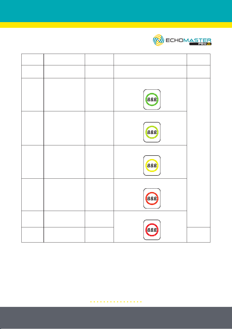
3: Rear Parking Assist
When the key is turned to the “ON” position and the Reverse gear is engaged,
the system is activated. If an obstacle is detected, its distance will be shown on
the display, along with an audible tone and visual alert.
The alarm method is as follows:
Audible and Visual Warning Display will show the obstacle distance and provide
warning beeps according to the distance of the obstacle. The alarm section will
be divided into 5 equal segments according to the farthest detection distance.
13
email - [email protected]
tel - 727-592-5991
(3) Rear Parking Assistant
When the key is turned to ON and R gear is engaged, the system starts to work, and the detected
demerit is recorded through the display to give an audible and visual alarm to remind the driver.
If there is no RCTA alarm, then follow the reversing working mode. The alarm method is as follows:
a. If there's an obstacle being detected, the trigger cable will provide a low level output, and if
there's being detected, it will provide floating output
b. Audible and visible warning Display show object distance and provide warning beep according
to the distance of the object; The alarm section be will divided into 5 segments equally according
to the farthest detection distance.
Distance display
Distance bar
Note: A. The color bars are segmented according to the longest distance of 5 equal parts;
B. The "- P -" area is 1/8 of the farthest detection distance; When displaying "- P -", the buzzer
will beep continuously;
C. The frequency of other alarm areas increases from 1Hz to 8Hz as the distance approaches;
Detection
Zone
Obstacle
Distance
Distance
Display
Color Bar Display
Audible
Alarm
1
Not detected
— —
Light bar is off
No
Tone
2
26.6’ - 32.8’
(8.1 - 10.0m)
1Hz-8Hz
Stepless
Gradient
20.0’ - 26.2’
(6.1 - 8.0m)
4
13.4’ - 19.7’
(4.1 - 6.0m)
5
6.9’ - 13.1’
(2.1 - 4.0m)
4.1’ - 6.6’
(1.26 - 2.0m)
≤ 4.1’
(≤1.25m)
Solid
Tone
Bright yellow green stripes
Bright yellow stripes
Bright orange stripes
Bright red stripes
Bright green color stripes
26.6 - 32.8
(8.1 - 10.0)
20.0 - 26.2
(6.1 - 8.0)
3
6
7
13.4 - 19.7
(4.1 - 6.0)
6.9 - 13.1
(2.1 - 4.0)
4.1 - 6.6
(1.26 - 2.0)
-P-
Note:
A.The color bars are segmented into 5 equal parts according to the longest
distance.
B. The “- P -” area is 1/8 of the farthest detection distance; When displaying
“- P -”, the speaker will output a solid tone.
C. The frequency of other alarm areas increases from 1Hz to 8Hz as the
obstacle approaches.
14
email - [email protected]
tel - 727-592-5991
Illustrations are typical and may not match exact vehicle detail
Press four
Press
once “
▽”
Enter learning
mode
Learning
success
A long beep
Learning failure
Beep twice
In learning
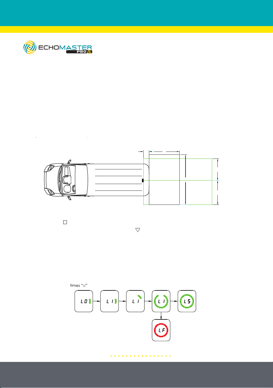
4: Learning Function
When the installation position of the radar is not at the outermost side of the
vehicle, the radar can easily detect the vehicle body, or vehicle accessories in the
rear bumper area, which can result in a false alarm. Therefore, it is necessary to
enter the learning mode to teach the radar to ignore the obstacle causing false
alerts.
Use the following steps to go through the learning function.
A. Move the vehicle to an open area and confirm that there are no obstacles
other than body accessories within (a*b) distances of the radar.
(4) Learning Function
When the installation position of the radar is not at the outermost side of the vehicle, the radar is
easy to detect the accessories of the vehicle or vehicle body, which will result in false alarm.
Therefore, in order not to make false alarm, it is necessary to enter into the learning mode to
make the radar ignore the object.
Users need to follow the following steps to realize the learning function:
a. Move the vehicle to an open area and confirm that there are no obstacles other than
body accessories within (a*b)m of the radar;
b. Power on and wait for system self diagnosis to complete;
c. Press the button
“□” four times, the buzzer will beep once to enter the learning setting mode.
Short press the "
▽" setting button, and the display will display "L1". Release the setting button,
and the system will enter the learning mode. The green bars will light up one by one during the
learning process, and the learning results will be displayed after the learning is completed. If
"LS" is displayed and one beep is made, it means the learning is successful. If "LF" is displayed
and two beeps are made, it means the learning is failed
;
a > 4*L1, and a > 9.84’ (3m);
b > W1 + W2, and b > 19.7’ (6m);
a
W2
W1
L1
b
Press four
times
“□”
Press
once “
▽”
Enter learning
mode
Learning
success
A long beep
Learning failure
Beep twice
In learning
(5) Rear Collision Warning (RCW)
When the key is turned to ON and any gear but R is engaged, the system starts to work.If any one
of the following two conditions is met, and the hazard warning light is off, the RCW alarm will be
triggered (control the flashing of the hazard warning light through the trigger line); after the alarm
finished, the hazard warning light will be turned off
a. L < 0.3s*V2;
b. TTC < 1.5s;
Note: TTC = L / (V2-V1)
L
V1
V2
9.84’ (3m)
B. Power on and wait for the system’s self diagnosis to complete.
C. Press the “ “ button four times, the buzzer will beep once to select the
learning mode setting. Short press the “ “ button one time so the display shows
“L1.” The system will now enter learning mode. The green bars will light up
one by one during the learning process and the results will be displayed after
the process is completed. If “L5” is displayed and one beep is heard, then the
learning process was successful. If “LF” is displayed and two beeps are heard,
then the learning process has failed. Retry the learning mode if the process fails
the first time.
15
email - [email protected]
tel - 727-592-5991
Illustrations are typical and may not match exact vehicle detail
5: Rear Collision Warning (RCW)
The system is active when the key is turned to the “ON” position and any gear,
except reverse is engaged. If any one of the following two conditions is met,
and the hazard warning light is off, the RCW alarm will be triggered (controlling
the flashing of the hazard warning light through the trigger wire). After the alert is
finished, the hazard warning light will turn off.
(4) Learning Function
When the installation position of the radar is not at the outermost side of the vehicle, the radar is
easy to detect the accessories of the vehicle or vehicle body, which will result in false alarm.
Therefore, in order not to make false alarm, it is necessary to enter into the learning mode to
make the radar ignore the object.
Users need to follow the following steps to realize the learning function:
a. Move the vehicle to an open area and confirm that there are no obstacles other than
body accessories within (a*b)m of the radar;
b. Power on and wait for system self diagnosis to complete;
c. Press the button
“□” four times, the buzzer will beep once to enter the learning setting mode.
Short press the "
▽
" setting button, and the display will display "L1". Release the setting button,
and the system will enter the learning mode. The green bars will light up one by one during the
learning process, and the learning results will be displayed after the learning is completed. If
"LS" is displayed and one beep is made, it means the learning is successful. If "LF" is displayed
and two beeps are made, it means the learning is failed
;
a > 4*L1, and a > 9.84’ (3m);
b > W1 + W2, and b > 19.7’ (6m);
a
W2
W1
L1
b
Press four
times
“□”
Press
once “
▽”
Enter learning
mode
Learning
success
A long beep
Learning failure
Beep twice
In learning
(5) Rear Collision Warning (RCW)
When the key is turned to ON and any gear but R is engaged, the system starts to work.If any one
of the following two conditions is met, and the hazard warning light is off, the RCW alarm will be
triggered (control the flashing of the hazard warning light through the trigger line); after the alarm
finished, the hazard warning light will be turned off
a. L < 0.3s*V2;
b. TTC < 1.5s;
Note: TTC = L / (V2-V1)
L
V1
V2
9.84’ (3m)
16
email - [email protected]
tel - 727-592-5991
Illustrations are typical and may not match exact vehicle detail
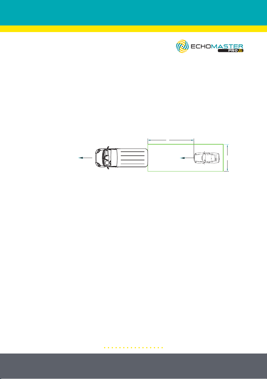
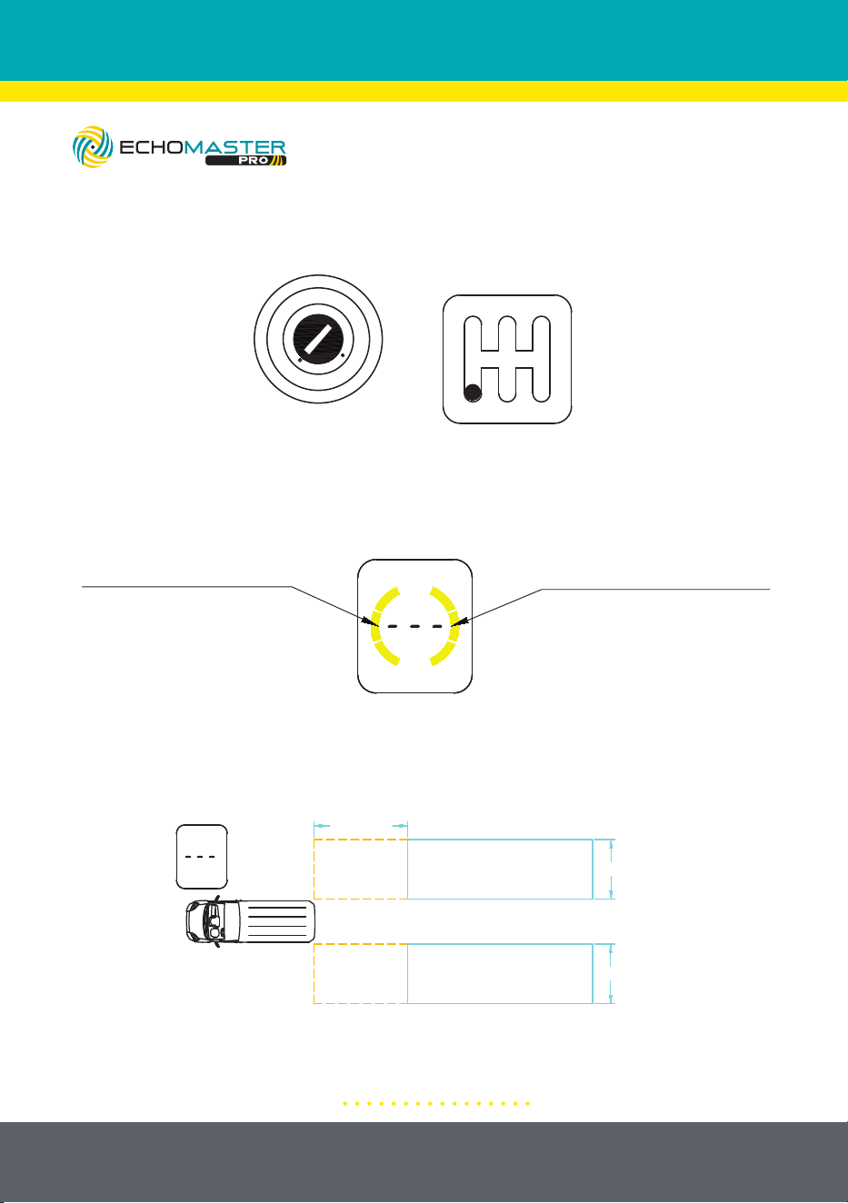
6: Blind Spot Detection BSD/Lane Change Aid (LCA)
A. Conditions
B. Basic Functions
The left and right sides of the display have the same function and are
independent of each other.
The display warning area is as shown below:
Taking the right side of the display as an example, the function is as follows:
There is no car in the alarm area and the display does not show obstacles.
LOCK
ACC
ON
START
R
531
42
Any gear but R
(6) Blind Spot Detection BSD/Lane Change Aid (LCA)
a. Conditions
b. Basic functions
The left and right sides have the same function and are independent of each other.
The display warning area is as below:
Taking the right as an example, the function is as follows:
There is no car in the alarm area, and the display does not show objects;
There is no target vehicle in the BSD alarm area, and there is a vehicle in the LCA alarm
area, but the overtaking time > 3.5s, the display won't warning;
Right side warning areaLeft side warning area
BSD warning
area
LCA warning area
BSD warning
area
LCA warning area
Max: 164.0’ (50m)
BSD warning
area
LCA warning area
BSD warning
area
LCA warning area
Max: 164.0’ (50m)
14.7’(4.5m)
14.7’(4.5m)
32.8’(10m)
32.8’(10m)
14.7’(4.5m)
14.7’(4.5m)
17
email - [email protected]
tel - 727-592-5991
Illustrations are typical and may not match exact vehicle detail
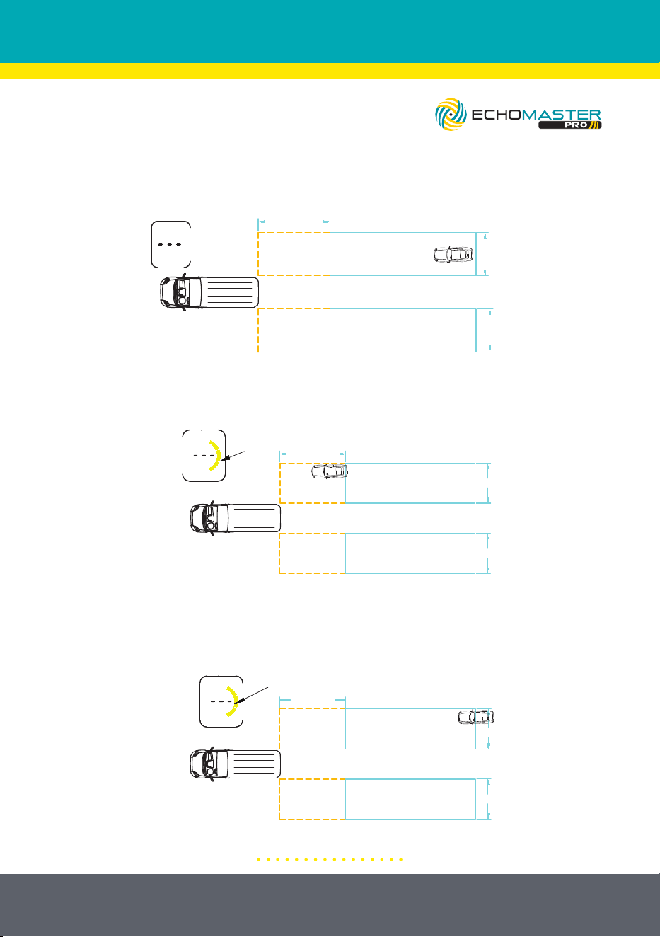
There is no vehicle in the BSD alarm area and there is a vehicle in the LCA alarm
area, but the overtaking time is greater than 3.5 seconds, the display will not
alert the driver.
If a vehicle is in the BSD warning area, a first-level alarm will be issued (the color
bar on the right side of the display will be ON)
If a vehicle is in the LCA warning area and the overtaking time is less than 3.5
seconds, a first-level alarm will be issued (the color bar on the right side of the
display will be ON)
LOCK
ACC
ON
START
R
531
42
Any gear but R
(6) Blind Spot Detection BSD/Lane Change Aid (LCA)
a. Conditions
b. Basic functions
The left and right sides have the same function and are independent of each other.
The display warning area is as below:
Taking the right as an example, the function is as follows:
There is no car in the alarm area, and the display does not show objects;
There is no target vehicle in the BSD alarm area, and there is a vehicle in the LCA alarm
area, but the overtaking time > 3.5s, the display won't warning;
Right side warning areaLeft side warning area
BSD warning
area
LCA warning area
BSD warning
area
LCA warning area
Max: 164.0’ (50m)
BSD warning
area
LCA warning area
BSD warning
area
LCA warning area
Max: 164.0’ (50m)
14.7’(4.5m)
14.7’(4.5m)
32.8’(10m)
32.8’(10m)
14.7’(4.5m)
14.7’(4.5m)
If the target vehicle is in the BSD warning area, a first-level alarm will be issued (the color bar on
the right side of the display will be ON);
If the target vehicle is in the LCA warning area and will overtaking the vehicle < 3.5s, a first-level
alarm will be issued (the color bar on the right side of the display will be ON);
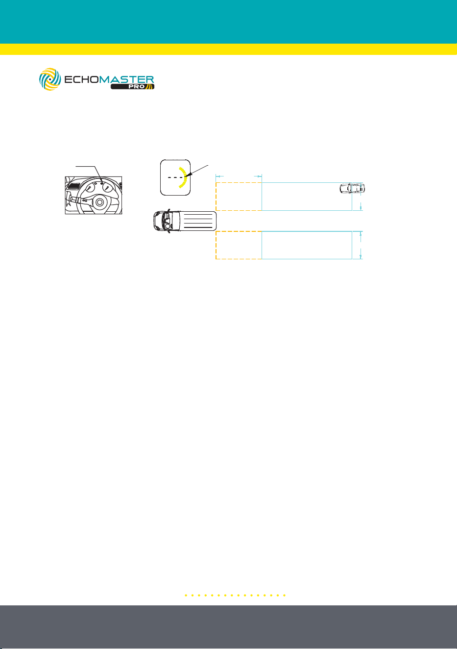
In the case of the first-level alarm, if turn right, the second-level alarm will be issued (the color bar
on the right side of the display will blink, and the buzzer will beep twice);
ON
BSD warning
area
LCA warning area
BSD warning
area
LCA warning area
Max: 164.0’ (50m)
BSD warning
area
LCA warning area
BSD warning
area
LCA warning area
ON
Max: 164.0’ (50m)
10
0
20
30
40
50
60
Right turn
Blink
Blink
BSD warning
area
LCA warning area
BSD warning
area
LCA warning area
Max: 164.0’ (50m)
32.8’(10m)
14.7’(4.5m)
14.7’(4.5m)
14.7’(4.5m)
14.7’(4.5m)
32.8’(10m)
32.8’(10m)
14.7’(4.5m)
14.7’(4.5m)
If the target vehicle is in the BSD warning area, a first-level alarm will be issued (the color bar on
the right side of the display will be ON);
If the target vehicle is in the LCA warning area and will overtaking the vehicle < 3.5s, a first-level
alarm will be issued (the color bar on the right side of the display will be ON);
In the case of the first-level alarm, if turn right, the second-level alarm will be issued (the color bar
on the right side of the display will blink, and the buzzer will beep twice);
ON
BSD warning
area
LCA warning area
BSD warning
area
LCA warning area
Max: 164.0’ (50m)
BSD warning
area
LCA warning area
BSD warning
area
LCA warning area
ON
Max: 164.0’ (50m)
10
0
20
30
40
50
60
Right turn
Blink
Blink
BSD warning
area
LCA warning area
BSD warning
area
LCA warning area
Max: 164.0’ (50m)
32.8’(10m)
14.7’(4.5m)
14.7’(4.5m)
14.7’(4.5m)
14.7’(4.5m)
32.8’(10m)
32.8’(10m)
14.7’(4.5m)
14.7’(4.5m)
18
email - [email protected]
tel - 727-592-5991
Illustrations are typical and may not match exact vehicle detail
In the case of the first-level alarm, when turning right, the second-level alarm will
be issued (the color bar on the right side of the display will blink and the buzzer
will beep twice).
If the target vehicle is in the BSD warning area, a first-level alarm will be issued (the color bar on
the right side of the display will be ON);
If the target vehicle is in the LCA warning area and will overtaking the vehicle < 3.5s, a first-level
alarm will be issued (the color bar on the right side of the display will be ON);
In the case of the first-level alarm, if turn right, the second-level alarm will be issued (the color bar
on the right side of the display will blink, and the buzzer will beep twice);
ON
BSD warning
area
LCA warning area
BSD warning
area
LCA warning area
Max: 164.0’ (50m)
BSD warning
area
LCA warning area
BSD warning
area
LCA warning area
ON
Max: 164.0’ (50m)
10
0
20
30
40
50
60
Right turn
Blink
Blink
BSD warning
area
LCA warning area
BSD warning
area
LCA warning area
Max: 164.0’ (50m)
32.8’(10m)
14.7’(4.5m)
14.7’(4.5m)
14.7’(4.5m)
14.7’(4.5m)
32.8’(10m)
32.8’(10m)
14.7’(4.5m)
14.7’(4.5m)
19
email - [email protected]
tel - 727-592-5991
Illustrations are typical and may not match exact vehicle detail
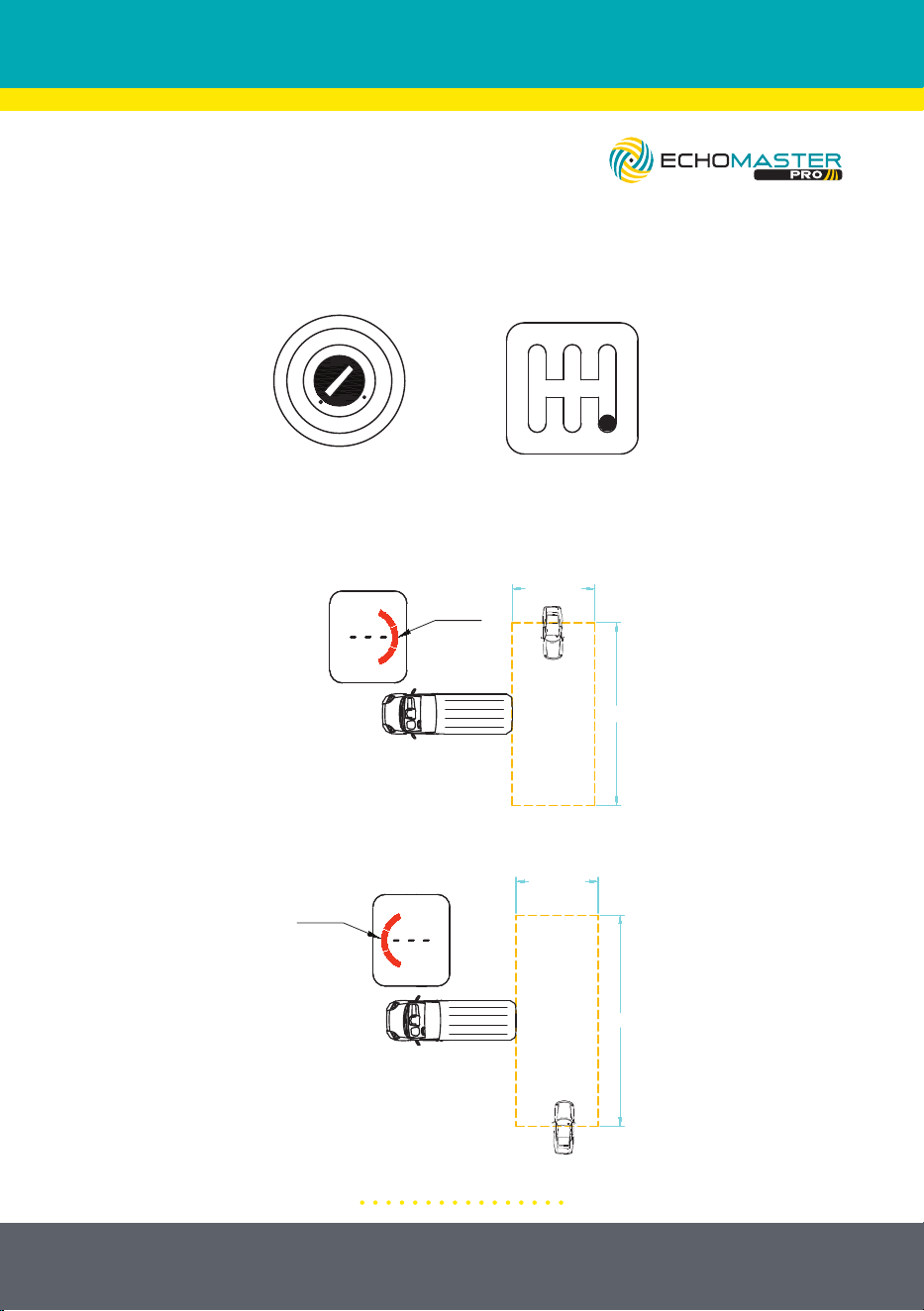
7: Rear Cross Traffic Alert (RCTA)
A. Conditions
B. Warning Functions
When an obstacle on the right side enters the warning area, the color bar on the
right side of the display blinks and beeps twice.
When an obstacle on the left side enters the warning area, the color bar on the
left side of the display blinks and beeps twice.
(7) Rear Cross Traffic Alert (RCTA)
b. Warning functions
LOCK
ACC
ON
START
R
5
31
4
2
In Reverse gear
When an obstacle on the right side enters the warning area, the color bar on the right side of
the display blink and beeps twice;
When an obstacle on the left side enters the warning area, the color bar on the left side of the
display blink and beeps twice;
Blink
Blink
a. Conditions
16.4’(5m)
16.4’(5m)
65.6’(20m)
65.6’(20m)
20
email - [email protected]
tel - 727-592-5991
INSTALLATION NOTES
1: This product is designed to work with 12-24V battery vehicles.
2: The front of the radar sensor should not be covered by metal objects.
3: Connect cables according to the labels.
4: Make sure the wiring harness is secured and far away from heat
sources, sharp edges and any moving vehicle components. Avoid pulling on the
harnesses.
5: Wrap all wire to wire connections with electrical tape, or cover with heat
shrink.
6: If there is ice or dirt on the surface of the sensor, please clean it off for the best
operation. Paint will also affect the detection ability.
7: Obstacles such as soft sponges, spheres, and sharp pointed objects can not
be detected easily.
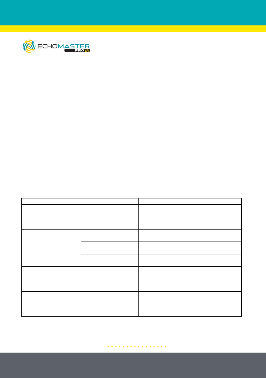
TROUBLESHOOTING
Symptom Cause Solution
Poor wire connection
Check all wire connections between display and
the vehicle
Display is damaged or
faulty
Replace the display
Poor wire connection
Check harness connections between the display
and the sensor
Sensor is damaged or
faulty
Replace the sensor
Display is damaged or
faulty
Replace the display
Alam does not sound when
object is in blind spot and
turn signal is active
Poor wire connection
Check harness connections and make sure left
and right turn signal wire connections are correct
and solid
Vehicle body or object on
body is detected
Enter display menu and reprogram learning
function; refer to Step 4: Learning Function
Sensor is damaged or
faulty
Replace the sensor
Display does not turn on
when power is applied
Display shows red bar and
beeps twice when power is
applied
There are no obstacles, but
system continues to beep
when in reverse

21
email - [email protected]
tel - 727-592-5991
TECHNICAL PARAMETERS
5. Display Installation
(1) Select location: Choose a suitable location so that the driver can easily observe the content
displayed on the monitor
(2) Monitor fixation: Clean the adhesive position of the monitor, remove the 3M
adhesive from the bottom of the monitor, and stick it in a suitable position. It can also
be fixed with screws.
6. Technical Parameters
DC 9-16V
<350mA@12V
-40˚ F-176˚ F
-40˚ F-176˚ F
77-81GHz
FMCW
30°
150°
2TX,4RX
Operating Voltage
Current Consumption
Working Temperature
Storage Temperature
Frequency
Modulation Mode
Vertical Angle
Horizontal Angle
Antenna Type
22
email - [email protected]
tel - 727-592-5991
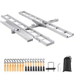
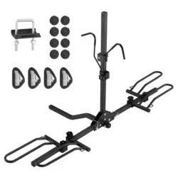
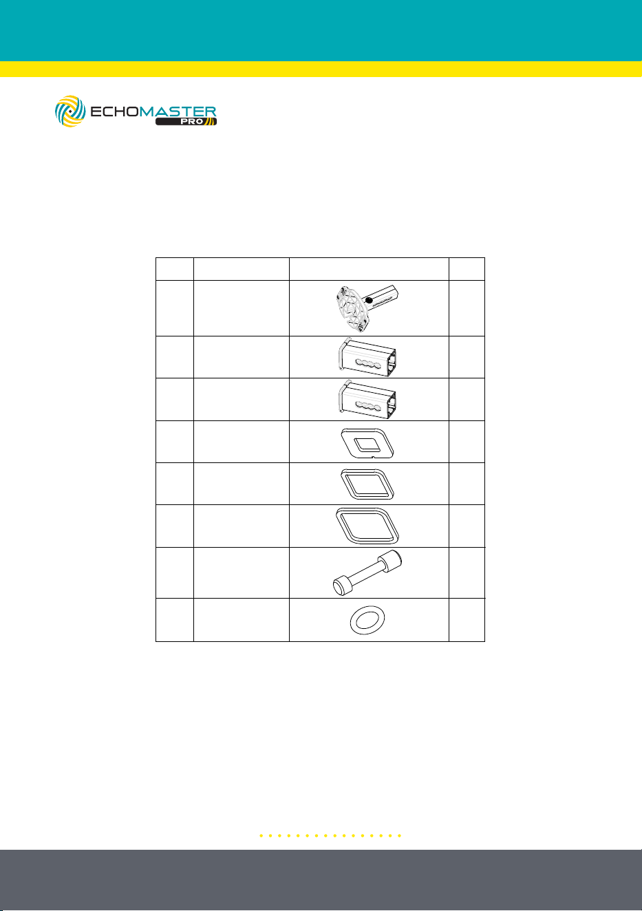
ACCESSORY COMPONENTS
No.
Name
Diagram
2.0” Square Tube
1
2
3
4
2.5” Square Tube
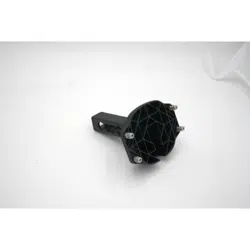
Hitch Bracket
Qty
1
4
1
1
4
5
8 10
4
1
6
7
1.25” Gasket
2.0” Gasket
2.5” Gasket
Locking Hitch Pin
O-Ring
RD1-HITCH-BRK
23
email - [email protected]
tel - 727-592-5991
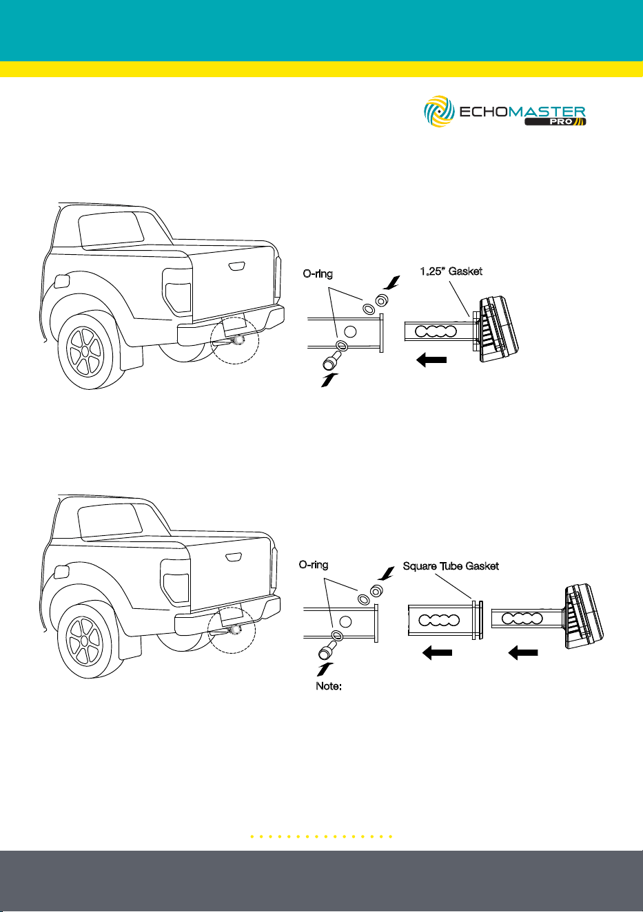
Illustrations are typical and may not match exact vehicle detail
1.25” Gasket
Note: The number of O-rings and
gaskets is selected based on what
makes for a snug fit
O-ring
Square Tube Gasket
Note:
The square tube is selected according to the
size of the trailer hitch;
The size and quantity of square tube gaskets
should be selected based on what makes for
snug fit
O-ring
Vehicles Equipped with 1.25” Hitch Receiver
Vehicles Equipped with 2” or 2.5” Hitch Receiver

Phone – 727-592-5991
E-Mail – [email protected]
EchoMaster is a Power Brand of Stinger
EchoMaster.com
REV. BF051225