ASSEMBLY AND USER’S GUIDE
SKU: 26512
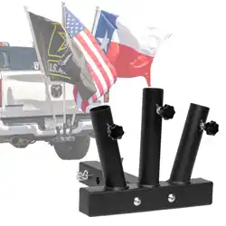
UNIVERSAL HITCH MOUNT
FLAG POLE HOLDER
26513
2 FLAG POLE HOLDER
26512
SKU: 26513
FOR 2” HITCH RECEIVER
3 FLAG POLE HOLDER


TABLE OF CONTENTS
1
10DISCLAIMER
8Parts Diagram
8REPLACEMENT PARTS
5ASSEMBLY INSTRUCTIONS
5ASSEMBLY
3PACKAGING CONTENTS
3PRODUCT INFORMATION
2
Legends and Symbols
2IMPORTANT SAFETY INSTRUCTIONS
1TABLE OF CONTENTS
10Customer Service
10Disclaimer
4INTRODUCTION
5Step 2: Adjustable Knob Attachment
5Step 1: Hitch Receiver And Flag Pole Holder Attachment
6Step 4: Fix Pin Attachment
6Step 3: Hitch Mount Attachment
7Completed
7Step 5: Wave Pin Attachment
IMPORTANT SAFETY INSTRUCTIONS
2
For safety reasons, children should not be allowed to use this product.
Packing materials and plastic bags are not toys. Keep them away from children to prevent the risk
of suffocation.
Failure to comply with all instructions and warnings may lead to severe bodily
injury or even death. For optimal safety and functionality, it is advisable to have the product installed
and serviced by a certified service professional. Prior to using this product, installers, operators, and
owners must carefully review these warnings and all instructions provided in the owner's manual. It
is essential to leave these warnings and the owner's manual with the owner for their reference and
safety.
ATTENTION INSTALLER: This manual contains vital information regarding the installation,
operation, and safe use of this product. It is essential to provide this manual to the end user of the
product. Failure to read and follow all instructions could lead to severe injuries.
USE OF NON-XTREMEPOWERUS REPLACEMENT PARTS VOIDS WARRANTY
DANGER: Ignoring these hazards can result in death, severe personal injury, or
significant property damage.
WARNING: Indicates potential hazards that can result in severe personal injury,
death, or significant property damage. Ignoring these warnings presents a real
danger.
CAUTION: Indicates potential hazards that can result in minor or moderate
personal injury, property damage, or actions that are unpredictable and unsafe.
Ignoring these cautions presents a potential hazard.
NOTICE: This label indicates important special instructions that are not directly
related to hazards.
This guide provides instructions for installing and using the UNIVERSAL HITCH MOUNT FLAG
POLE HOLDER . If you have any questions about the product, please contact XtremepowerUS.
This guide contains important information about safely installing and operating this product. After
installation, make sure to share this information with the owner/operator or leave it with them for
their reference.
Legends and Symbols
When you come across the safety-alert symbol on the product or in this manual, pay attention to the
following signal words and remain vigilant about the potential for personal injury.
IMPORTANT SAFETY INSTRUCTIONS
DANGER
WARNING
WARNING
CAUTION
NOTE
DANGER
3
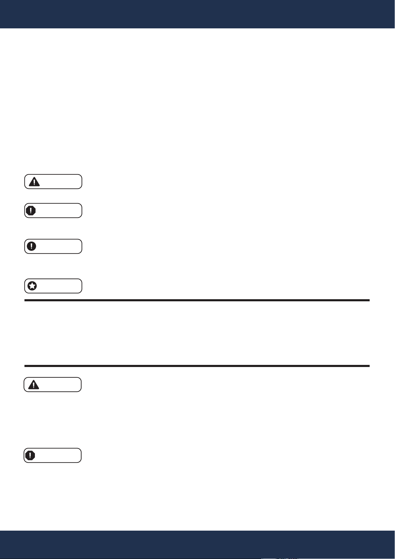
PRODUCT INFORMATION
PACKAGING CONTENTS
PRODUCT INFORMATION
PARTS # 1
2” HITCH
1 PC(S)
PARTS #
2
2-FLAG POLE HOLDER
1 PC(S)
PARTS #
3
FIX PIN
1 PC(S)
PARTS #
4
ADJUSTABLE KNOB
2 PC(S)
SKU 26512
M8 x 30
PARTS #
5
NUT
2 PC(S)
PARTS #
6
WAVE PIN
1 PC(S)
PARTS #
7
LOCK NUT
2 PC(S)
PARTS #
8
WASHER
2 PC(S)
M8
PARTS #
9
BOLT
2 PC(S)
M10 M10 M10 x 65
PARTS # 1
2” HITCH
1 PC(S)
PARTS #
2
3-FLAG POLE HOLDER
1 PC(S)
PARTS #
3
FIX PIN
1 PC(S)
PARTS #
4
ADJUSTABLE KNOB
3 PC(S)
SKU 26513
M8 x 30
PARTS #
5
NUT
3 PC(S)
PARTS #
6
WAVE PIN
1 PC(S)
PARTS #
7
LOCK NUT
2 PC(S)
PARTS #
8
WASHER
2 PC(S)
M8
PARTS #
9
BOLT
2 PC(S)
M10 M10 M10 x 65
PRODUCT INFORMATION
4
StarkUSA Universal Hitch Mount Flag Pole Holder is engineered for secure and flexible flag
display on vehicles with a 2” hitch receiver. Perfect for events, parades, or stationary flag-flying,
this holder maintains flag stability and visibility.
It accommodates various flag sizes and styles, keeping the flag anchored during movement.
The installation process is simple, fitting most standard 2” hitch receivers, which makes this
holder a key accessory for displaying flags.
INTRODUCTION
SKU 26512
SKU 26513
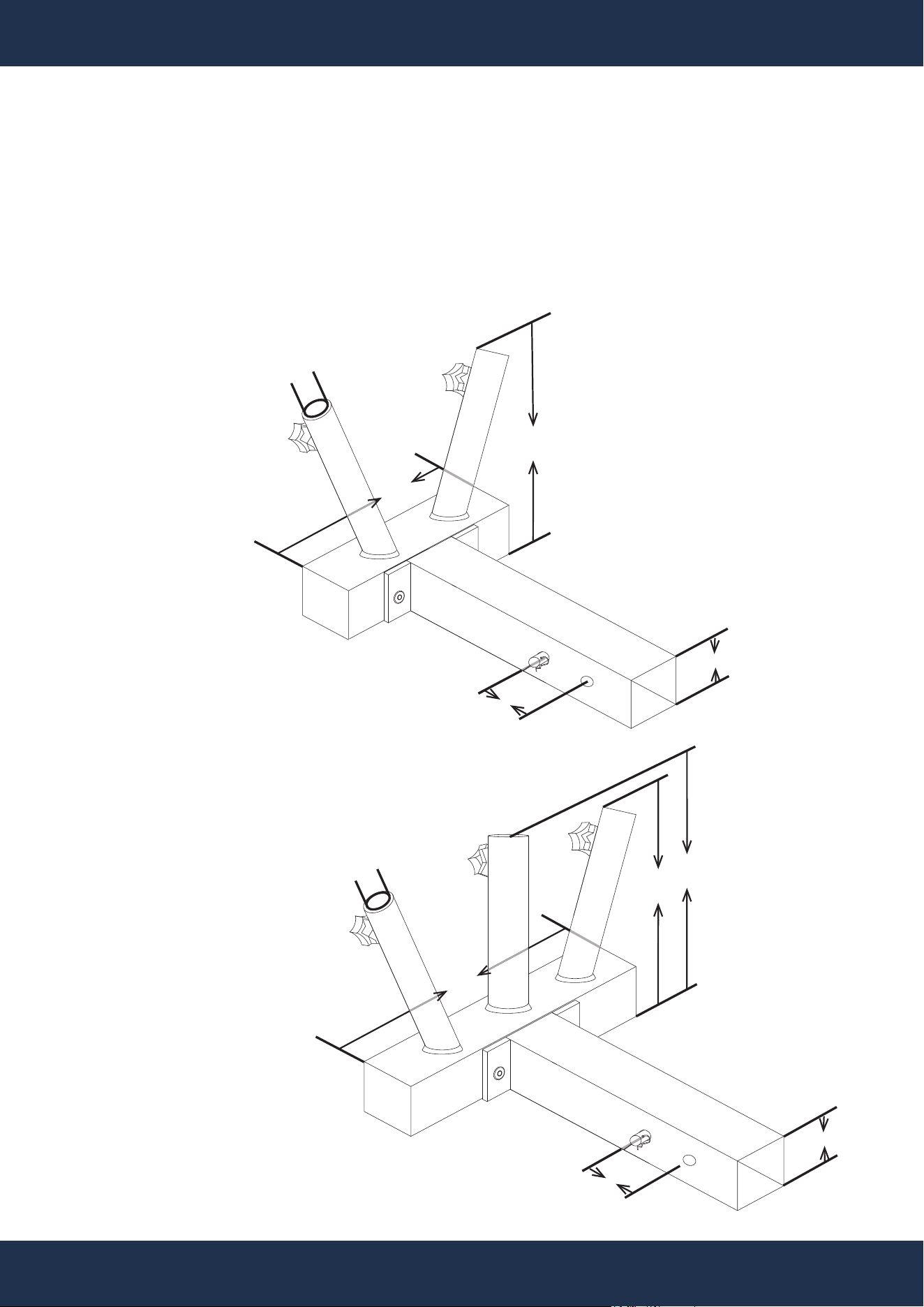
DIMENSIONS
8.5”
1.4”
(INNER)
9”
2”
11”
8.5”
1.4”
(INNER)
9.5”
2”
2”
2”
ASSEMBLY
5
ASSEMBLY
ASSEMBLY INSTRUCTIONS
SKU: 26512 SKU: 26513
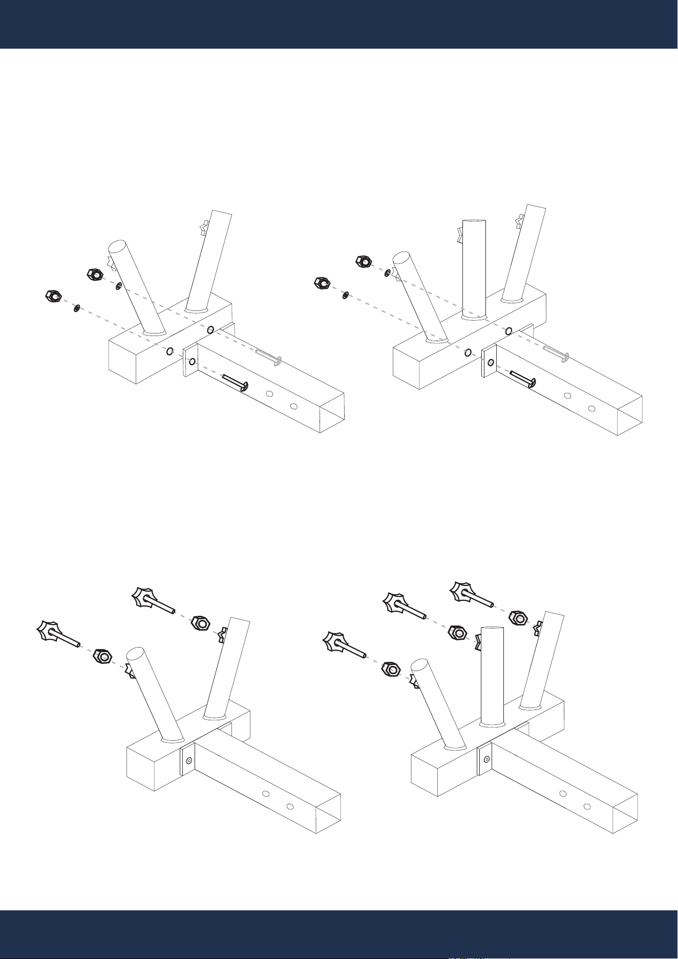
Step 1: Hitch Receiver And Flag Pole Holder Attachment
SKU: 26512 SKU: 26513
Step 2: Adjustable Knob Attachment
PARTS# 8
PARTS#
1
PARTS#
2
PARTS# 9
PARTS# 9
PARTS# 7
PARTS# 8
PARTS#
1
PARTS#
2
PARTS# 9
PARTS# 9
PARTS# 7
PARTS# 4
PARTS# 4
PARTS# 4
PARTS# 4
PARTS# 4
PARTS# 5
PARTS# 5
PARTS# 5
PARTS# 5
PARTS# 5
ASSEMBLY
6
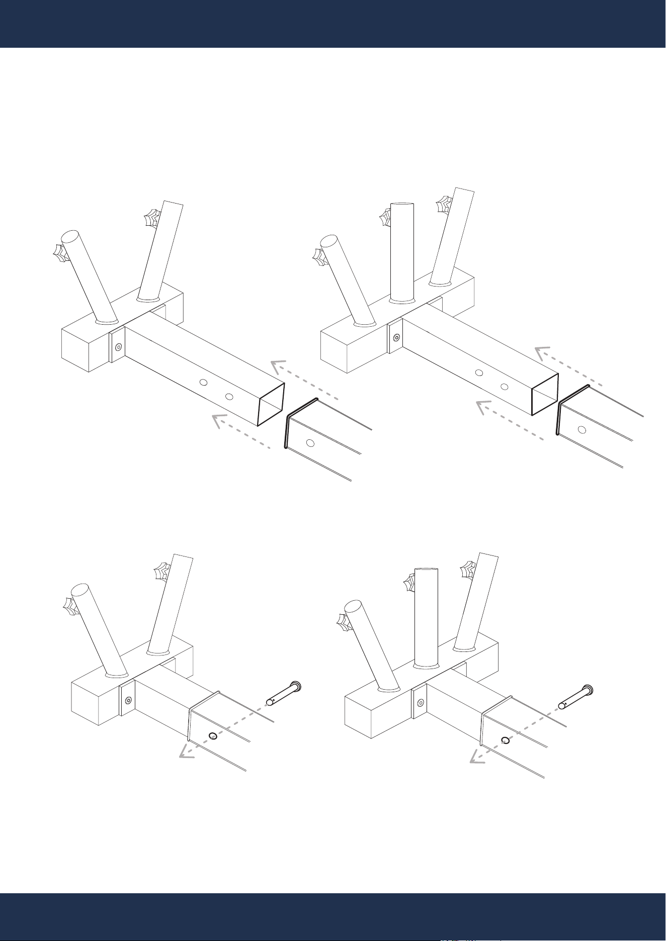
Step 3: Hitch Mount Attachment
Step 4: Fix Pin Attachment
SKU: 26512 SKU: 26513
SKU: 26512 SKU: 26513
PARTS#
3
PARTS#
3
RECEIVER TUBE
(NOT INCLUDED)
RECEIVER TUBE
(NOT INCLUDED)
ASSEMBLY
7
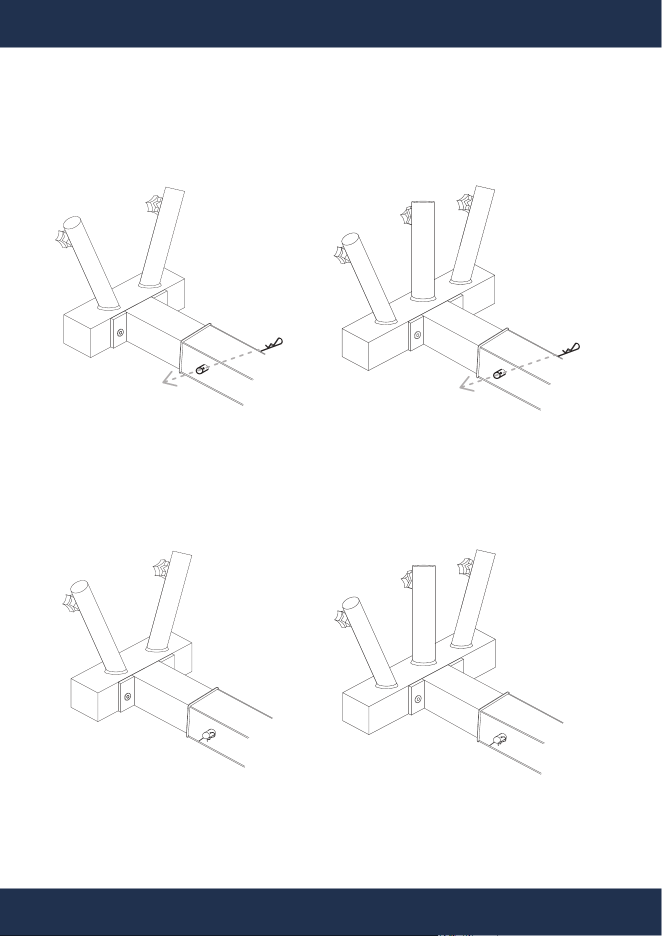
Step 5: Wave Pin Attachment
SKU: 26512 SKU: 26513
SKU: 26512 SKU: 26513
Completed
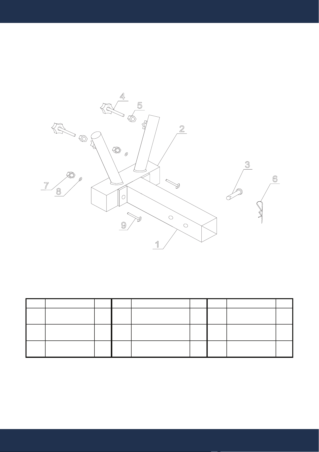
REPLACEMENT PARTS
8
REPLACEMENT PARTS
SKU: 26512
PARTS DIAGRAM
1
2
3
4
5
6
7
8
9
ITEM DESCRIPTION QTY ITEM DESCRIPTION QTY ITEM DESCRIPTION QTY
1
2" HITCH
RECEIVER
1
4
ADJUSTABLE KNOB
M8 x 30
2
7
LOCK NUT
M10
2
2
2-FLAG POLE
HOLDER
1 5 NUT
M8
2 8 WASHER
M10
2
3 FIX PIN 1 6 WAVE PIN 1 9 BOLT
M10 x 65
2
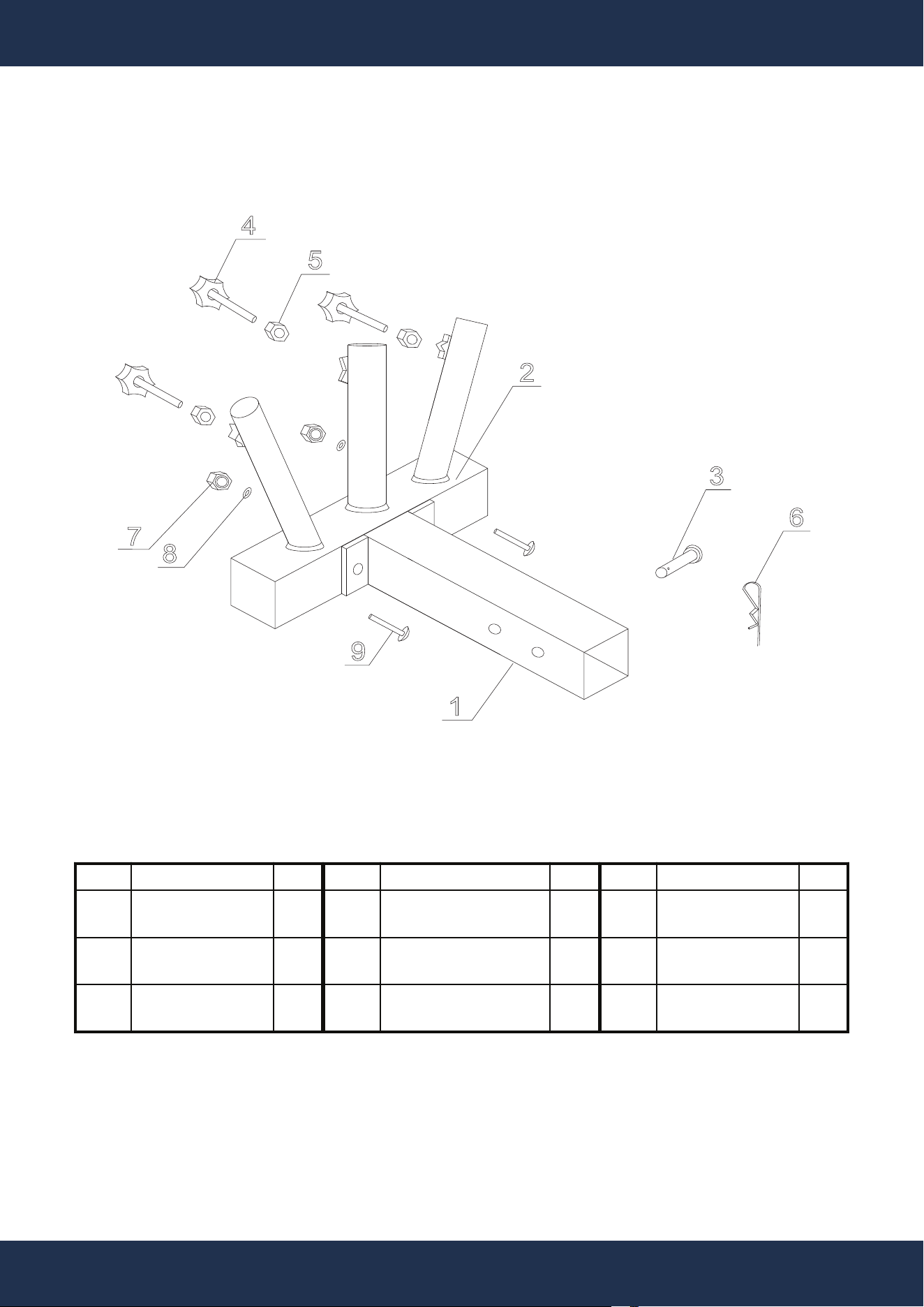
REPLACEMENT PARTS
9
SKU: 26513
ITEM DESCRIPTION QTY ITEM DESCRIPTION QTY ITEM DESCRIPTION QTY
1
2" HITCH
RECEIVER
1 4
ADJUSTABLE KNOB
M8 x 30
3 7 LOCK NUT
M10
2
2
3-FLAG POLE
HOLDER
1
5
NUT
M8
3
8
WASHER
M10
2
3 FIX PIN 1 6 WAVE PIN 1 9 BOLT
M10 x 65
2
1
2
3
4
5
6
7
8
9

DISCLAIMER
10
DISCLAIMER
PLEASE READ THE FOLLOWING CAREFULLY
The manufacturer and/or distributor have provided the parts list and assembly diagram in this
manual for reference purposes only. They do not make any representation or warranty to the buyer
that they are qualified to make repairs to the product or replace any parts of the product. In fact, the
manufacturer and/or distributor expressly state that all repairs and parts replacements should be
undertaken by certified and licensed technicians, and not by the buyer.
The buyer assumes all risk and liability arising from their repairs to the original product or
replacement parts or arising from their installation of replacement parts. It is strongly advised that
qualified professionals handle any repairs or replacements to ensure safety and proper functioning
of the product. Improper installation and operation may result in injury, property damage, or voiding
of warranty. The manufacturer and/or distributor shall not be held responsible for any accidents,
damages, or malfunctions resulting from the buyer's installation and operation of the product. It is
essential to follow all safety guidelines and recommendations provided in this manual and to seek
professional assistance if unsure about the installation or operation procedures.
CUSTOMER SERVICE
If you have any questions about ordering our pool pumps and replacement parts or pool products,
please feel free to contact us using the following contact information:
Customer Service and Technical Support
Phone: (909) 628-0880
Email: [email protected]
Hours of Operation: Monday – Friday, 9AM – 4PM (CST)
