Download the app
& activate product
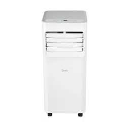
MAP05S1AWT-A
MAP07S1AWT-A
USER MANUAL
Before using this product, please read this manual carefully and keep it for future reference.
The design and specifications are subject to change without prior notice for product improvement. Consult
with the dealer or the manufacturer for details.
PORTABLE AIR CONDITIONER

2
CONTENTS
Read This Manual
This manual contains helpful tips for the proper use and maintenance of the
dehumidifier. Implementing preventive care can save significant time and money
throughout the unit's lifespan.
• For support, please call the Service Center at 1-866-646-4332.
• This unit is not intended for use by people (including children) with reduced
physical, sensory or mental capabilities or lack of experience and knowledge, unless
they have been given supervision or instruction concerning use of the appliance by
a person responsible for their safety.
• Children should be supervised to ensure that they do not play with the air conditioner.
• The unit shall be installed in accordance with national wiring regulations.
• Do not operate the air conditioner in a humid room such as a bathroom or laundry
room.
CAUTION
THANK YOU FOR CHOOSING MIDEA!
Before using your new Midea product, please review this manual thoroughly to
ensure safe and effective operation of its features and functions.
CONTENTS ...................................................................................................................................2
SAFETY INSTRUCTIONS..........................................................................................................3
BEFORE GETTING STARTED.................................................................................................14
PRODUCT INSTALLATION......................................................................................................17
OPERATION INSTRUCTIONS.................................................................................................23
REMOTE CONTROL INSTRUCTIONS..................................................................................25
DRAINAGE GUIDE......................................................................................................................40
CLEANING AND MAINTENANCE.........................................................................................41
TROUBLESHOOTING TIPS......................................................................................................43
WARRANTY..................................................................................................................................44
APP INSTRUCTIONS .................................................................................................................33
3
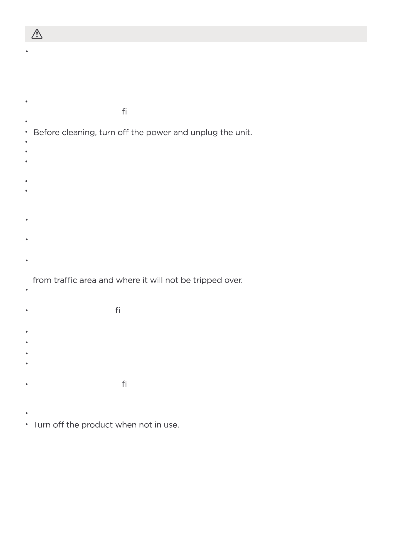
SAFETY PRECAUTIONS
Explanation of Symbols
To prevent injury to the user, or personal and property damage, these instructions
must be followed. Incorrect operation due to ignoring of instructions may cause
harm or damage. The level of risk is shown by the following indications.
WARNING
CAUTION
This symbol indicates a risk of property damage or serious
consequences.
This symbol indicates a risk of personal injury or serious harm.
WARNING
Installation must be performed according to the installation instructions. Improper
installation can cause water leakage, electrical shock, or fire.
Use only the included accessories and parts, and specified tools for the installation.
Using non-standard parts can cause water leakage, electrical shock, fire, and injury
or property damage.
Ensure the outlet is grounded and matches the required voltage. The power cord
features a three-prong grounding plug for shock protection. Voltage details are
on the unit's nameplate.
The unit must be used with a properly grounded wall receptacle. If the receptacle
is not adequately grounded or protected by the correct fuse or circuit breaker
(as specified by the unit's maximum current on the nameplate), have a qualified
electrician install the appropriate receptacle.
Install the unit on a at, sturdy surface. Failure to do so could result in damage or
excessive noise and vibration.
The unit must be kept free from obstruction to ensure proper function and to mitigate
safety hazards.
Do not modify the length of the power cord or use an extension cord to power the unit.
Do not share a single outlet with other electrical appliances. Improper power supply can
cause
re or electrical shock.
Do not install the air conditioner in a wet room, such as a bathroom or laundry room.
Excessive exposure to water can cause electrical components to short circuit.
Do not touch the unit with wet or damp hands or when barefoot.
the unit and unplug it from
damage to the unit due to
The air conditioner should be used in such a way that it is protected from moisture.
(i.e. condensation, splashed water, etc.) Do not place or store the air conditioner
where it can fall or be pulled into water or any other liquid. Unplug immediately if it
occurs.
the main power supply immediately. Visually inspect the unit to ensure there is no
damage. If there are suspicions that the unit may be damaged, contact a technician
or customer service for assistance.
lightning.
The power supply cord with this
air conditioner contains a current
detection device designed to reduce
the risk of
re.
In the event that the power supply
cord is damaged, it can not be
repaired. It must be replaced with a
cord from the manufacturer.
Grounding type wall receptacle
Do not, under any
circumstances, cut,
remove or bypass
the grounding prong.
Power supply cord with 3-prong grounding
plug and current detection device.
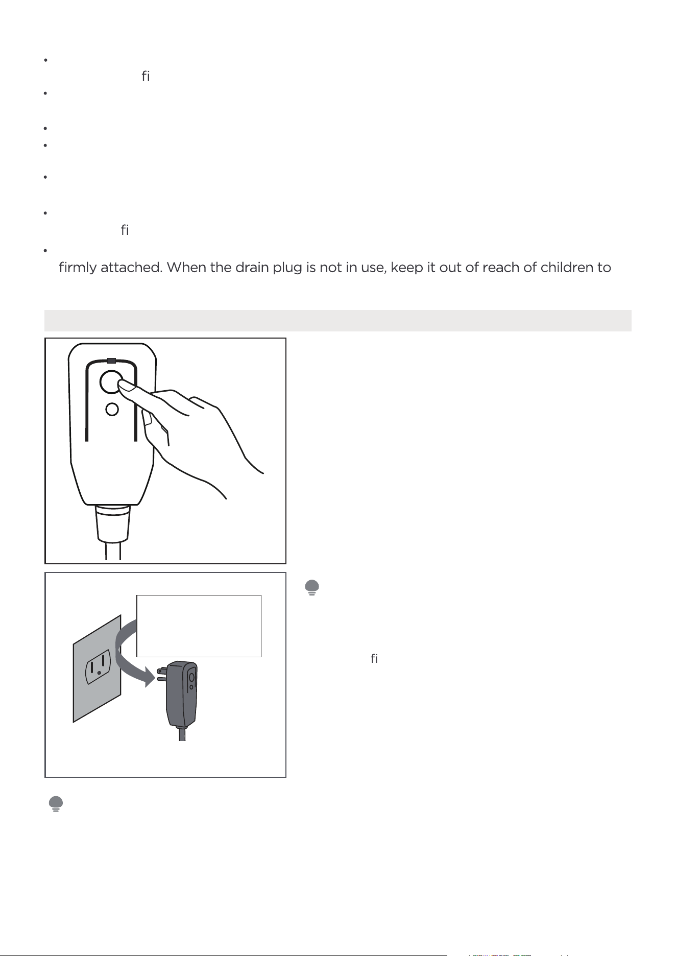
The power supply cord contains a
current measuring device that detects
damage to the power cord. Test the
power supply cord as follows:
1. Plug in the air conditioner.
2. The power supply cord will have TWO
buttons on the plug head. Press the
TEST button. A click will be heard as
the RESET button pops out.
3. Press the RESET Button. A click will
be heard as the button engages.
4. The power supply cord is now
sup
plying electricity to the unit. (On
some products this is also indicated
by a light on the plug head.)
RESET
TEST
Plug in &
press RESET
Operation of Current Device
• Do not use this device to turn the unit on or off.
• Always make sure the RESET button is pushed in for correct operation.
• If the power supply cord does not reset when the TEST button is pressed or
cannot be reset, it must be replaced. Please contact customer service for
assistance.
4
Do not install the unit in a location that may be exposed to combustible gas, as this
could cause
re.
The unit has wheels to facilitate moving. Make sure not to use the wheels on thick
carpet or to roll over objects, as this could cause the unit to tip over.
All wiring must be performed strictly in accordance with the wiring diagram located
inside of the unit.
The unit's circuit board(PCB) is designed with a fuse to provide overcurrent protection.
The speci
cations of the fuse are printed on the circuit board, such as: T 3.15A/250V, etc.
When the water drainage function is not in use, keep the upper and lower drain plug
avoid a choking hazard.
Do not operate a unit that has been dropped or damaged.
Ensure the unit remains at least 3ft (1m) away from any combustible materials such as
bedding, curtains, and furniture
NOTE
NOTE
5
CAUTION
This unit is not intended for use by persons (including children) with reduced physical,
sensory, or mental capabilities, or those lacking experience and knowledge, unless they
have received supervision or instruction concerning its use from a person responsible
for their safety. Children should be supervised to ensure they do not play with the unit.
Children must be monitored around the unit at all times.
If the supply cord is damaged, it must be replaced by the manufacturer, its service
agent or similarly quali
ed persons in order to avoid a hazard.
Prior to cleaning or other maintenance, the unit must be disconnected from the
supply mains.
Do not remove any fixed covers. Never use this unit if it is not working properly, or
if it has been dropped or damaged.
Do not run cord under carpeting. D
o not cover cord with throw rugs, runners, or
similar coverings. Do not route cord under furniture or appliances. Arrange cord away
Do not operate unit with a damaged cord, plug, power fuse or circuit breaker. Discard
unit or return to an authorized service facility for examination and/or repair.
To reduce the risk of
re or electric shock, do not use this fan with any solid-state
speed control device.
The unit shall be installed in accordance with national wiring regulations.
Contact the authorized service technician for repair or maintenance of
this unit.
Do not cover or obstruct the inlet or outlet grilles.
Disconnect the power if strange sounds, smell, or smoke are present.
Do not press the control panel buttons with anything other than fingers.
Do not remove any fixed covers. Never use this unit if it is not working properly,
or if it has been dropped or damaged.
Do not operate or stop the unit by inserting or pulling out the
power cord plug.
Do not use h
azardous chemicals to clean or come into contact with the unit. Do not
use the unit in the presence of inflammable substances or vapor(i.e. alcohol,
insecticides, petrol etc.)
Do not use this unit for functions other than those described in this instruction manual.
Always transport the air conditioner in a vertical position and stand on a stable, level
surface during use.
Always contact a quali
ed person to carry out repairs. If the damaged power supply
cord must be replaced, use a new power supply cord obtained from the product
manufacturer. Do not repair the damaged cord.
Hold the plug by the head of the power plug when taking it out.
6
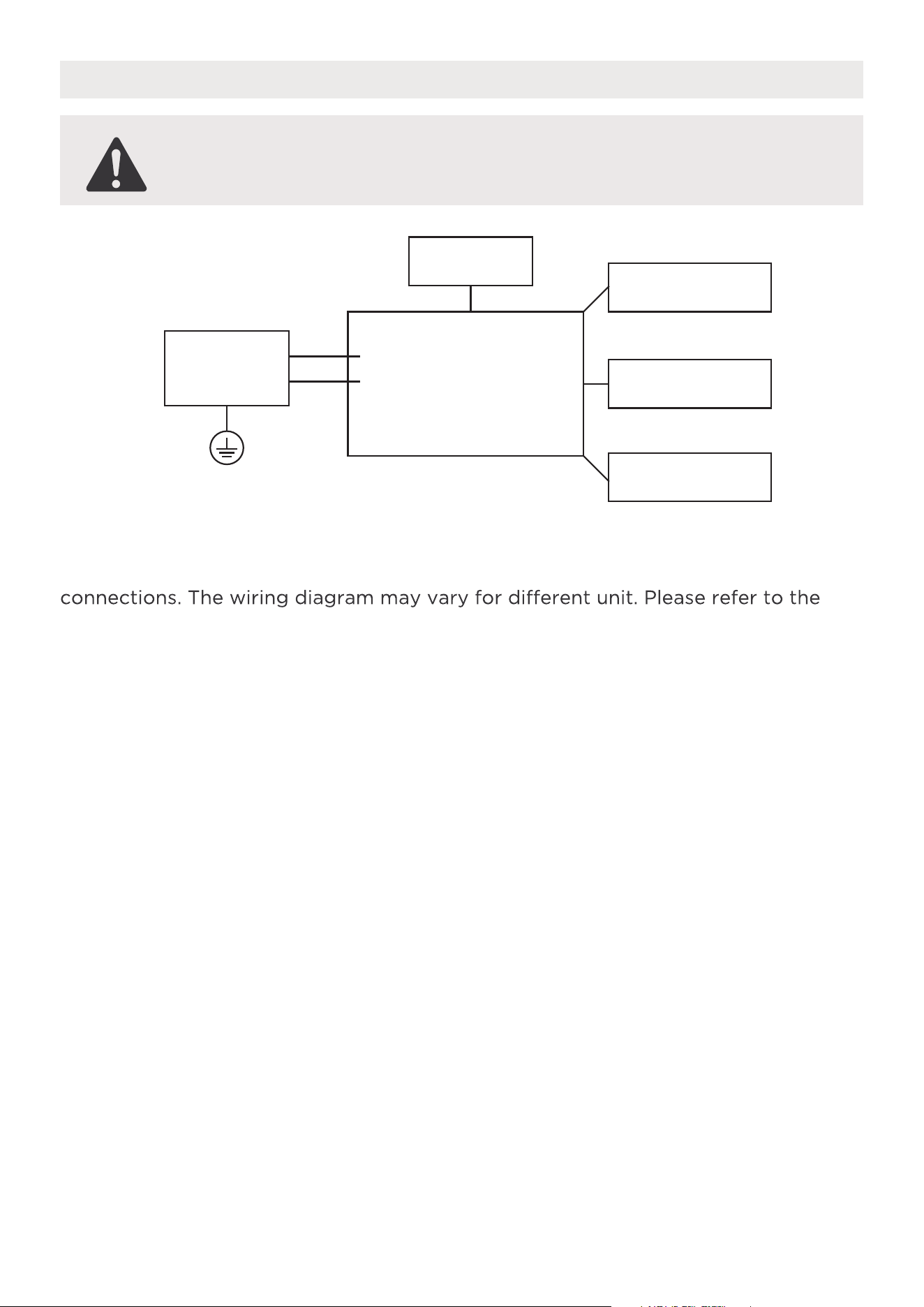
Electric Work
WARNING:
BEFORE PERFORMING ANY ELECTRICAL OR WIRING WORK, TURN OFF THE MAIN
POWER TO THE SYSTEM.
NOTE: Please strictly follow the wiring label attached to the machine for all wiring
wiring diagram on the purchased unit. The above wiring diagram is a simplified
version for preliminary illustration purposes only.
Main Control
Compressor
Fan Motor
Display
Power
Supply
L/AC L/L1/L-IN
N/AC N/L2/N-IN
Other
Electronic Type
7
WARNING:
-
-
-
-
Servicing shall only be performed as recommended by the manufacturer.
Maintenance and repair requiring the assistance of other skilled personnel shall
be carried out under the supervision of the person competent in the use of
flammable refrigerants.
DO NOT modify the length of the power cord or use an extension cord to
power the unit.
DO NOT share a single outlet with other electrical appliances.
Improper power supply can cause fire or electrical shock.
Please follow the instruction carefully to handle, install, clear, service the
unit to avoid any damage or hazard.
SAFETY
MANUAL
FOR R32 REFRIGERANT MODEL
North America Products
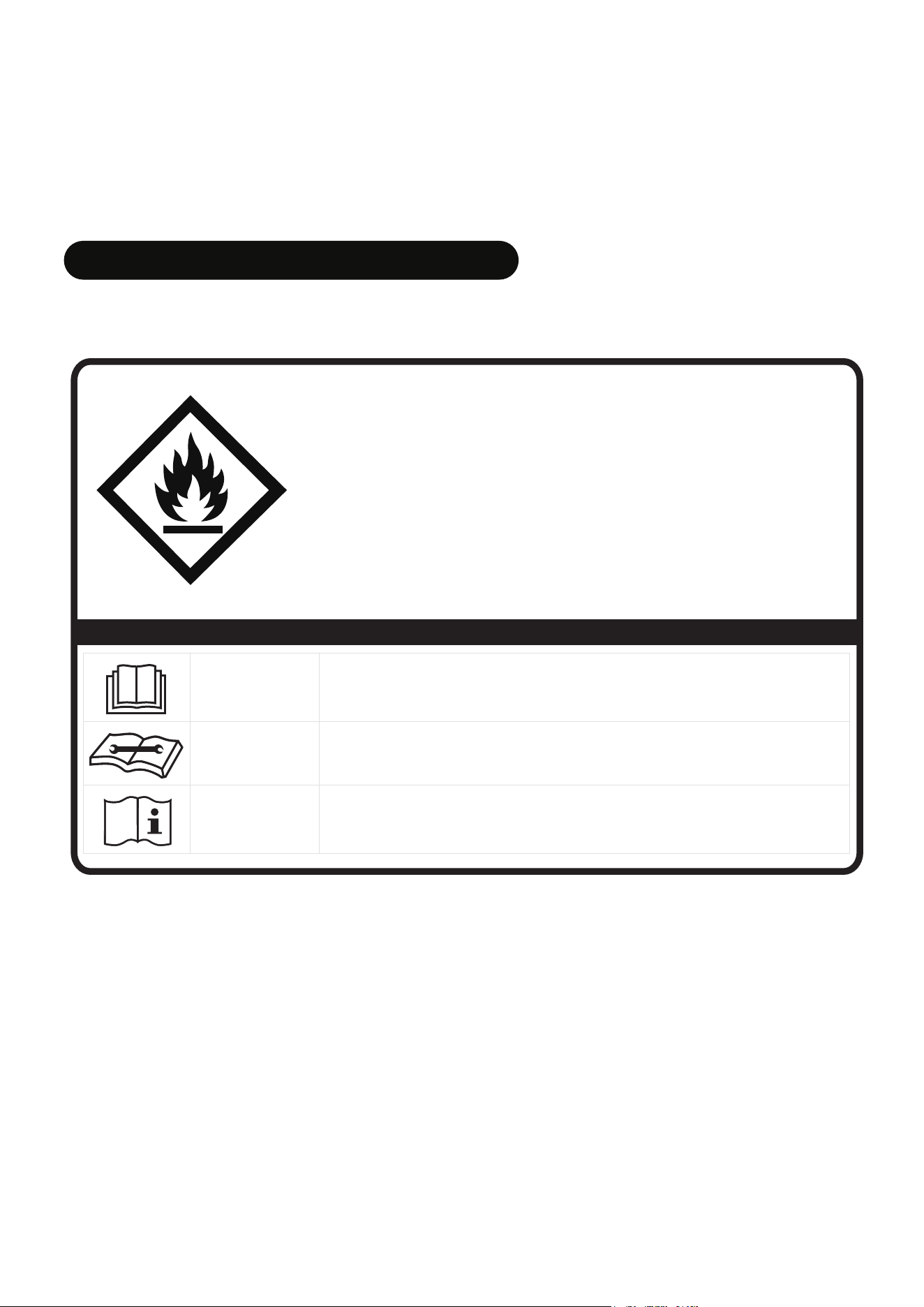
CAUTION:
Risk of fire
flammable materials
IMPORTANT NOTE: Read this manual
carefully before installing or operating
the new unit. Make sure to save this
manual for future reference.
Explanation of symbols displayed on the unit
CAUTION
This symbol indicates that the operation manual should be read
carefully.
CAUTION
This symbol indicates that a service personnel should be handling this
unit with reference to the installation manual.
CAUTION
This symbol indicates that information is available such as the
operating manual or installation manual.
A2L

8
Flammable refrigerant R32 is used within the unit.
-
-
-
-
-
-
When maintaining or disposing the appliance, the refrigerant (R32) shall be
recovered properly, shall not discharge to air directly.
Compliance with national gas regulations shall be observed.
Keep ventilation openings clear of obstruction.
The unit shall be stored so as to prevent mechanical damage from occurring.
The unit shall be stored in a well-ventilated area where the room size corresponds
to the room area as specified for operation.
Any person who is involved with working on or breaking into a refrigerant circuit
should hold a current valid certificate from an industry-accredited assessment
authority, which authorizes their competence to handle refrigerants safely in
accordance with an industry recognized assessment specification. All training shall
follow the ANNEX HH requirements of UL 60335-2-40 4th Edition.
Examples for such working procedures are:
• Breaking into the refrigerating circuit;
• Opening of sealed components;
• Opening of ventilated enclosures.
-
-
-
-
-
No open fire or device like switch which may generate spark/arcing shall be
around the unit to avoid causing ignition of the flammable refrigerant used.
Please follow the instructions carefully when storing or maintaining the unit
to prevent mechanical damage from occurring.
Do not use means to accelerate the defrosting process or to clean, other than
those recommended by the manufacturer.
The unit shall be stored in a room without continuously operating ignition sources
(i.e. open flames, an operating gas appliance) and ignition sources or (i.e. an
operating electric heater) close to the unit.
Do not pierce or burn.
Be aware that the refrigerants may not contain an odor.
9
1. Transport of equipment containing flammable refrigerants
See transport regulations.
2. Marking of equipment using signs
See local regulations.
3. Disposal of equipment using flammable refrigerants
See national regulations.
4. Storage of equipment/appliances
The storage of the unit should be in accordance with the applicable regulations
or instructions, whichever is more stringent.
5. Storage of packed (unsold) equipment
Storage package protection should be constructed such that mechanical damage
to the unit inside the package will not cause a leak of the refrigerant charge.
The maximum number of pieces of the units permitted to be stored together will
be determined by local regulations.
6. Information on servicing
1) Checks to the area
Prior to beginning work on systems containing flammable refrigerants, safety
checks are necessary to ensure that the risk of ignition is minimized. For repair to
the refrigerating system, the following precautions shall be complied with prior to
conducting work on the system.
2) Work procedure
Work shall be undertaken under a controlled procedure so as to minimize the risk
of a flammable gas or vapor being present while the work is being performed.
3) General work area
nature of work being carried out. Work in confined spaces shall be avoided. The
the area have been made safe by control of flammable material.
4) Checking for presence of refrigerant
The area shall be checked with an appropriate refrigerating detector prior to and
during work, to ensure the technician is aware of potentially flammable atmospheres.
Ensure that the leak detection equipment being used is suitable for use with
flammable refrigerants. (i.e. non-sparking, adequately sealed or intrinsically safe)
5) Presence of fire extinguisher
If any hot work is to be conducted on the refrigeration equipment or any
associated parts, appropriate fire extinguishing equipment shall be available to
hand. Have a dry powder or CO2 fire extinguisher adjacent to the charging area.

10
6) No ignition sources
No person carrying out work in relation to a refrigerating system which involves
exposing any pipe work that contains or has contained flammable refrigerant shall
use any sources of ignition in such a manner that it may lead to the risk of fire or
explosion. All possible ignition sources, including cigarette smoking, should be kept
during which flammable refrigerant can possibly be released to the surrounding
space. Prior to work taking place, the area around the unit is to be surveyed
to make sure that there are no flammable hazards or ignition risks. "No Smoking"
signs shall be displayed.
7) Ventilated area
Ensure that the area is in the open or that it is adequately ventilated before
breaking into the system or conducting any hot work. A degree of ventilation
shall continue during the period that the work is carried out. The ventilation
should safely disperse any released refrigerant and preferably expel it externally
into the atmosphere.
8) Checks to the refrigerating equipment
Where electrical components are being changed, they shall be fit for the purpose
and to the correct specifications. At all times the manufacturer's maintenance
and service guidelines shall be followed. If in doubt consult the manufacturer's
technical department for assistance. The following checks shall be applied to
installations using flammable refrigerants: the actual refrigerant charge is in
accordance with the room size within which the refrigerant containing parts are
installed; the ventilation machinery and outlets are operating adequately and are
not obstructed; if an indirect refrigerating circuit is being used, the secondary
circuit shall be checked for the presence of refrigerant; marking to the unit
continues to be visible and legible; markings and signs that are illegible shall be
corrected; and refrigerating pipe or components are installed in a position where
they are unlikely to be exposed to any substance which may corrode refrigerant
containing components, unless the components are constructed of materials
which are inherently resistant to being corroded or are suitably protected against
being so corroded.
9) Checks to electrical devices
Repair and maintenance to electrical components shall include initial safety
checks and component inspection procedures. If a fault exists that could
compromise safety, then no electrical supply shall be connected to the circuit
until it is satisfactorily dealt with. If the fault cannot be corrected immediately
but it is necessary to continue operation, an adequate temporary solution shall
be used. This shall be reported to the owner of the unit so all parties are
advised. Initial safety checks shall include:
That capacitors are discharged: this shall be done in a safe manner to avoid
possibility of sparking; that there no live electrical components and wiring are
exposed while charging, recovering or purging the system; that there is
continuity of earth bonding.
11
11. Removal and evacuation
When breaking into the refrigerant circuit to make repairs—or for any other
purpose - conventional procedures shall be used. However, for flammable
refrigerants it is important that best practice be followed, since flammability is a
consideration. The following procedure shall be adhered to:
-Safely remove refrigerant following local and national regulations;
-Evacuate;
-Purge the circuit with inert gas (optional for A2L);
-Evacuate (optional for A2L);
-Continuously flush or purge with inert gas when using flame to open circuit; and
-Open the circuit.
The refrigerant charge shall be recovered into the correct recovery cylinders if
venting is not allowed by local and national codes. For units containing flammable
refrigerants, the system shall be purged with oxygen-free nitrogen to render the
appliance safe for flammable refrigerants. This process may need to be repeated
several times. Do not use compressed air or oxygen to purge refrigerant systems.
7. Sealed electrical components shall be replaced.
8. Intrinsically safe components must be replaced.
9. Cabling
Check that cabling will not be subject to wear, corrosion, excessive pressure, vibration,
or fans.
10. Detection of flammable refrigerants
Under no circumstances shall potential sources of ignition be used in the searching
for or detection of refrigerant leaks. A halide torch (or any other detector using a
naked flame) shall not be used.
The following leak detection methods are deemed acceptable for systems containing
flammable refrigerants. Electronic leak detectors shall be used to detect flammable
refrigerants, but the sensitivity may not be adequate, or may need re-calibration.
(Detection equipment shall be calibrated in a refrigerant-free area.)
Ensure that the detector is not a potential source of ignition and is suitable for the
refrigerant used. Leak detection equipment shall be set at a percentage of the LFL of
the refrigerant and shall be calibrated to the refrigerant employed and the appropriate
percentage of gas (25% maximum) is confirmed. Leak detection fluids are suitable for
use with most refrigerants but the use of detergents containing chlorine shall be
avoided as the chlorine may react with the refrigerant and corrode the copper
pipe-work.
If a leak is suspected, all naked flames shall be removed/extinguished. If a leakage of
refrigerant is found which requires brazing, all of the refrigerant shall be recovered
remote from the leak. Removal of refrigerant shall be according to Removal and
evacuation.
12
13. Decommissioning
Before carrying out this procedure, it is essential that the technician is completely
familiar with the unit and all its detail. It is recommended good practice that
all refrigerants are recovered safely. Prior to the task being carried out, an oil and
refrigerant sample shall be taken in case analysis is required prior to re-use of
reclaimed refrigerant. It is essential that electrical power is available before the task
is commenced.
a) Become familiar with the unit and its operation.
b) Isolate system electrically.
c) Before attempting the procedure ensure that: mechanical handling equipment is
available, if required, for handling refrigerant cylinders; all personal protective
equipment is available and being used correctly; the recovery process is
supervised at all times by a competent person; recovery equipment and cylinders
conform to the appropriate standards.
d) Pump down refrigerant system, if possible.
e) If a vacuum is not possible, make a manifold so that refrigerant can be removed
from various parts of the system.
f) Make sure that cylinder is situated on the scales before recovery takes place.
g) Start the recovery machine and operate in accordance with instructions.
h) Do not overfill cylinders. (No more than 80% volume liquid charge.)
i) Do not exceed the maximum working pressure of the cylinder, even temporarily.
j) When the cylinders have been filled correctly and the process completed, make
sure that the cylinders and the equipment are removed from site promptly and
k) Recovered refrigerant shall not be charged into another refrigeration system
unless it has been cleaned and checked.
For units containing flammable refrigerants, refrigerants purging shall be achieved
by breaking the vacuum in the system with oxygen-free nitrogen and continuing
to fill until the working pressure is achieved, then venting to atmosphere, and finally
pulling down to a vacuum (optional for A2L). This process shall be repeated until
no refrigerant is within the system (optional for A2L). When the final oxygen-free
nitrogen charge is used. the system shall be vented down to atmospheric pressure
to enable work to take place.
The outlet for the vacuum pump shall not be close to any potential ignition sources,
and ventilation shall be available.
12. Charging procedures
In addition to conventional charging procedures, the following requirements shall
when using charging equipment. Hoses or lines shall be as short as possible to
minimize the amount of refrigerant contained in them. Cylinders shall be kept in an
appropriate position according to the instructions. Ensure that the refrigeration
system is earthed prior to charging the system with refrigerant. Label the system
when charging is complete (if not already). Extreme care shall be taken not to
overfill the refrigeration system. Prior to recharging the system it shall be pressure
tested with OFN. The system shall be leak tested on completion of charging but
prior to commissioning. A follow up leak test shall be carried out prior to leaving
the site.
13
14. Labeling
Equipment shall be labeled stating that it has been de-commissioned and emptied
of refrigerant. The label shall be dated and signed.
Ensure that there are labels on the equipment stating the equipment contains
flammable refrigerant.
15. Recovery
When removing refrigerant from a system, either for servicing or decommissioning,
it is recommended good practice that all refrigerants are removed safely.
When transferring refrigerant into cylinders, ensure that only appropriate refrigerant
recovery cylinders are employed. Ensure that the correct number of cylinders for
holding the total system charge is available. All cylinders to be used are designated
for the recovered refrigerant and labeled for that refrigerant (i.e. special cylinders
for the recovery of refrigerant). Cylinders shall be complete with pressure-relief
cylinders are evacuated and, if possible, cooled before recovery occurs.
The recovery equipment shall be in good working order with a set of instructions
concerning the equipment that is at hand and shall be suitable for the recovery of
the flammable refrigerant. If in doubt, the manufacturer should be consulted. In
addition, a set of calibrated weighing scales shall be available and in good working
order. Hoses shall be complete with leak-free disconnect couplings and in good
condition.
The recovered refrigerant shall be processed according to local legislation in the
correct recovery cylinder, and the relevant waste transfer note arranged. Do not
mix refrigerants in recovery units and especially not in cylinders.
If compressors or compressor oils are to be removed, ensure that they have been
evacuated to an acceptable level to make certain that flammable refrigerant does
not remain within the lubricant. The compressor body shall not be heated by an
open flame or other ignition sources to accelerate this process. When oil is drained
from a system, it shall be carried out safely.

BEFORE GETTING STARTED
Installing the AC
should take about
30 minutes.
The installation must be
carried out in strict
accordance with the
instructions in this manual.
M
a
nu
a
l
Assistance from a
helper is advisable.
Customer Service:
1-866-646-4332
AMBIENT TEMPERATURE RANGE FOR UNIT OPERATING
MODE Temperature Range
Cool 16-35°C (60-95°F)
Dry
13-35°C (55-95°F)
14
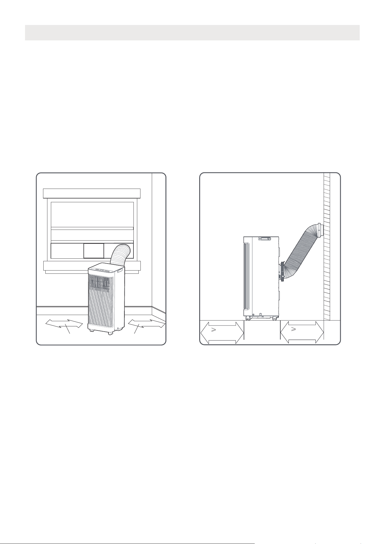
Requirements for space constraints in the installation location of the equipment
PRODUCT INSTALLATION LOCATION
The installation location should meet the following requirements:
- Make sure to install the unit on a level surface to minimize noise and vibration.
- The unit must be installed near a grounded plug, and the Collection Tray Drain (found on the back of
the unit) must be accessible.
- The unit should be located at least 30cm (12”) from the nearest wall to ensure proper air conditioning.
The air outlet of the unit should be at least 50cm(19.7”) away from obstacles.
- DO NOT cover the Intakes, Outlets or Remote Signal Receptor of the unit, as this co
uld cause damage
to the unit.
5
0
c
m
19.7
’’
5
0
c
m
19.7
’
’
≥
30cm(12’’)
≥30cm(12’’)
15
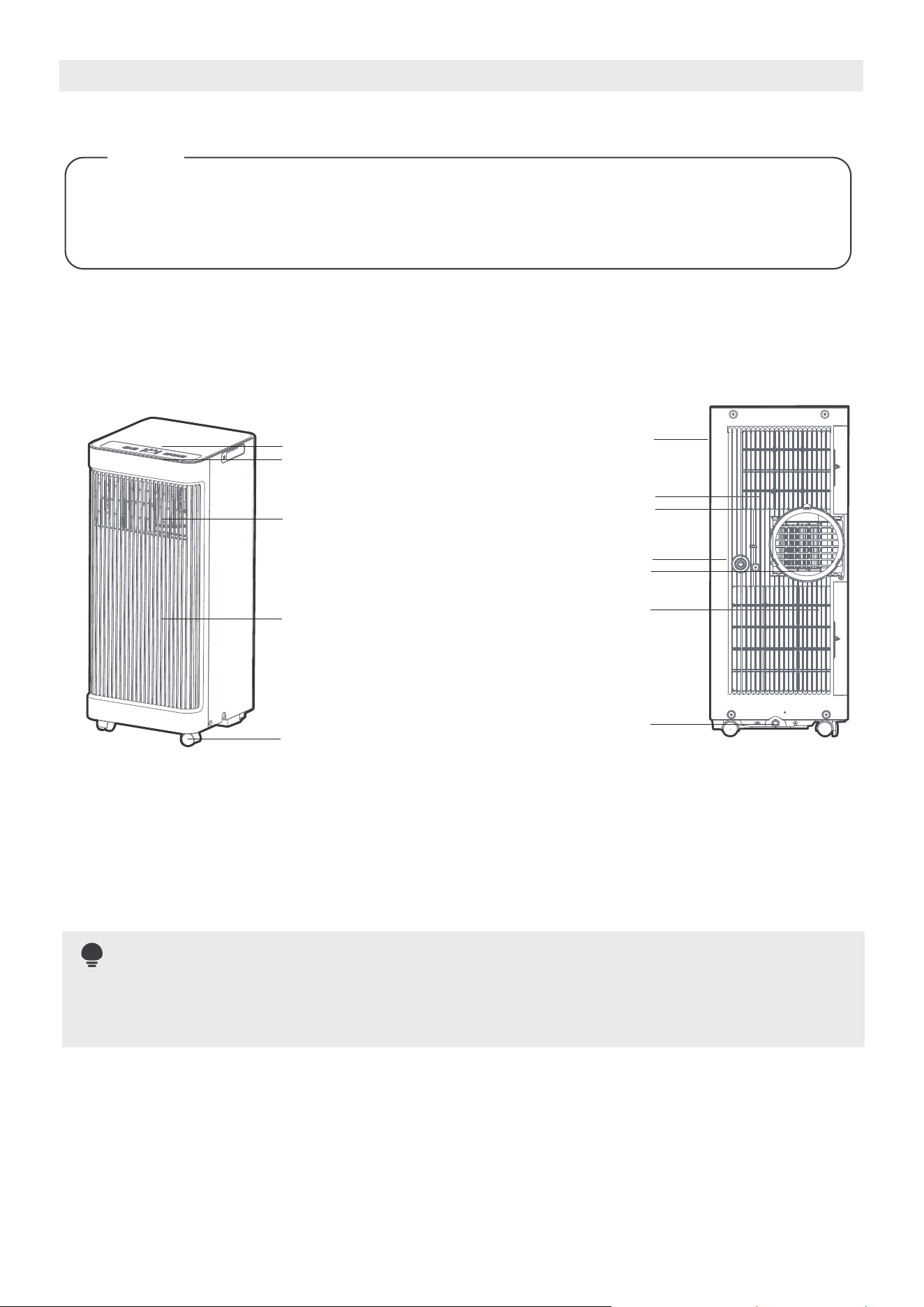
Product overview
NOTE
Design Notice
In order to ensure the optimal performance of our products, the design
specifications of the unit and remote control are subject to change without
prior notice.
Rear View
Handle
(both sides)
Air filter
Upper air intake
Air outlet
Lower air intake
Drain outlet
Bottom tray
drain outlet
Front View
Control panel
Remote signal receptor
Front panel
Wheels
Vertical louver control
lever-manual adjustment
(On some models)
All illustrations in the manual are for explanatory purposes only. The purchased unit may differ
slightly, though the overall shape will remain consistent. The unit can be operated using either the
control panel or the remote control.
16
Security Bracket and 2 Screws
E
Window Slider Assembly
xtended Exhaust Hose
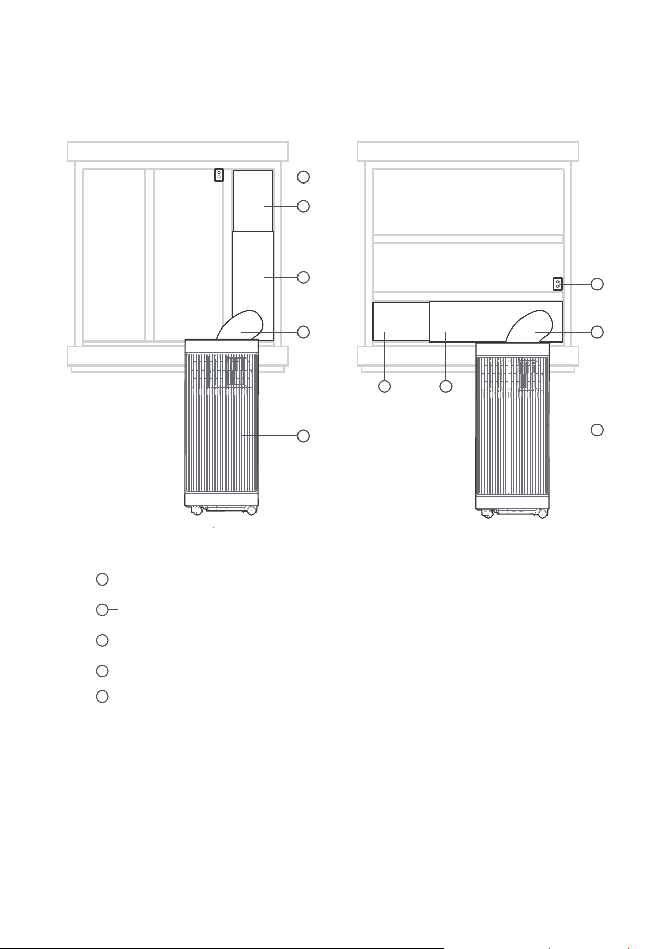
PRODUCT INSTALLATION
Installation Completion Display
Portable Air Conditioner
1
2
3
4
5
Sliding Window Installation Hung Window Installation
1
5
2
3 3
1 2
5
4
4
17
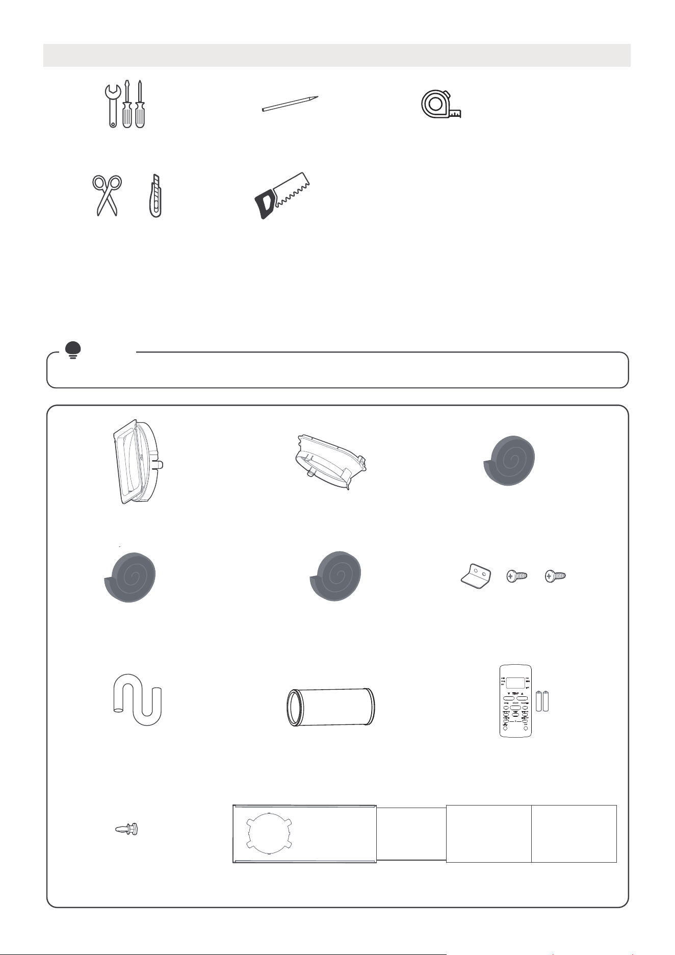
List of installation tools (not included)
Installation accessories
Screwdriver & Wrench Tape Measure
Scissors or Knife
Pencil
Saw (On some models, to shorten
window adaptor for narrow windows)
Air Exhaust Passage(1pc*) )cp1( rotpadA tinU
Exhaust Hose
Window
Slider A (1pc)
Window
Slider B (1pc)
Window
Slider C (1pc*)
Window
Slider D (1pc*)
Foam Seal A (Adhesive)
4 pc(*)
Foam Seal B (Adhesive)
2 pc
Foam Seal C (Non-adhesive)
2 pc(*)
Security Bracket and
2 Screws (1 set)
Drain Hose (1pc)
Bolt (3pc*)
NOTE
Remote Controller
and Battery (only
for remote control
models)(1 set*)
Items with (*) are on some models. Designs may vary slightly.
The window installation kit fits windows 19.4”-62.2”(49.3-158.1cm) and can be
shortened for smaller windows.
18
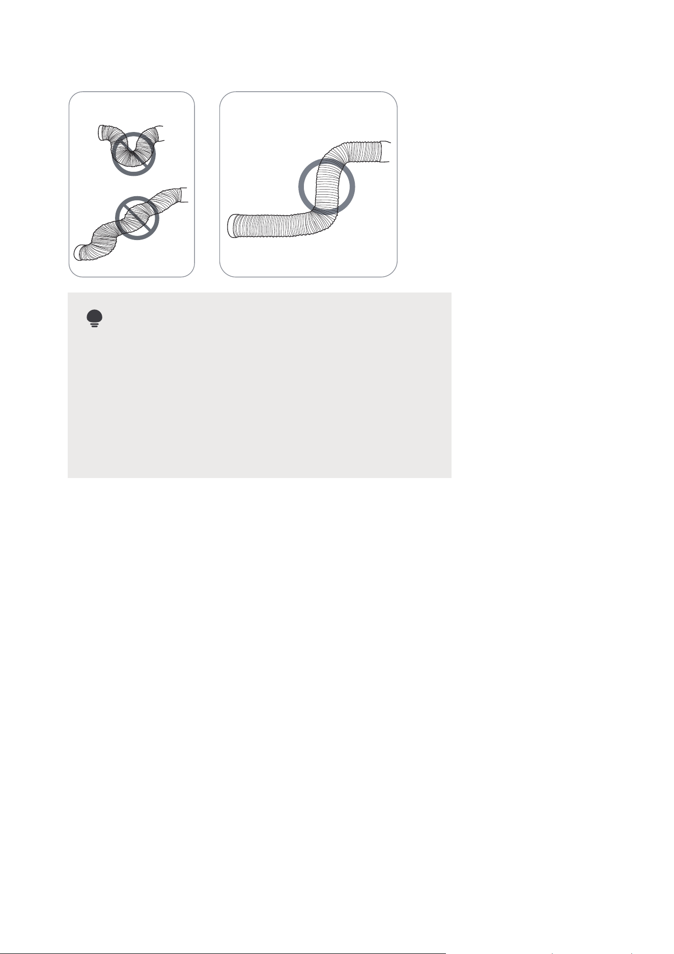
To ensure proper function, DO NOT overextend
or bend the hose. Make sure that there is no
obstacle around the air outlet of the exhaust
hose (in the range of 500mm) in order to ensure the
exhaust system works properly. All the illustrations
in this manual are for explanation purpose only.
T
The air conditioner may be slightly different.
he actual shape will remain the same.
NOTE:
INCORRECT
CORRECT
For optimal performance in operation
19
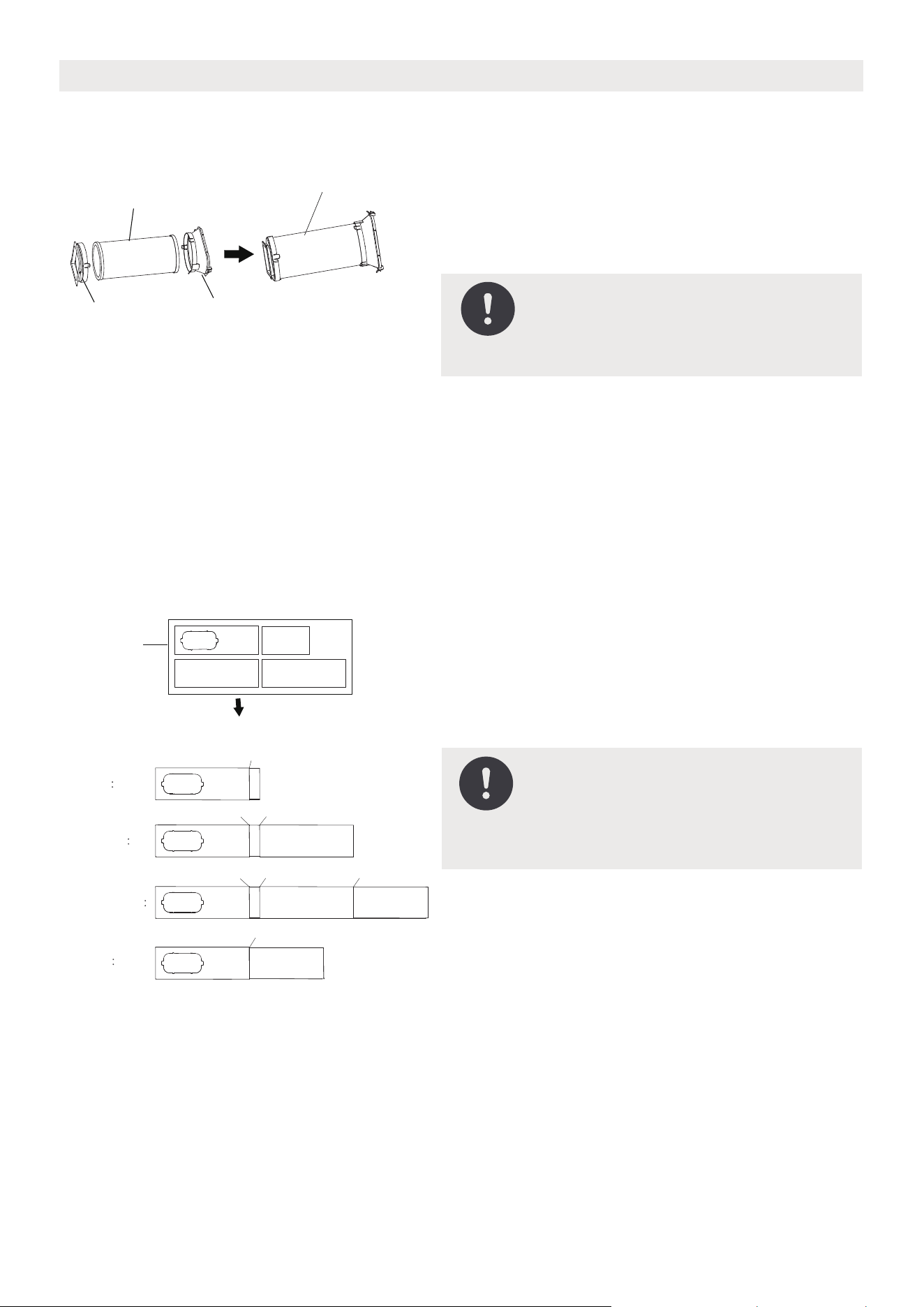
Exhaust hose and adaptors installation
Connect the adaptor to the unit and the window
1+2
Bolt
1+2+3
BoltBolt
1+2+3+4
BoltBoltBolt
1+4
Bolt
Window
Sliders
After assembly
Before assembly
NOTE: Please base the window
slider installation on the
accessories in the kit and the size
of the window.
Choose the window sliders according to the size of the
window. Some of the sliders may need to be cut to fit the
exact window size, make sure to cut the sliders carefully
if this is required.
Use bolts to fasten the window sliders once they are
adjusted to the proper length.
1. The Exhaust Hose assembly installation
(window type)
2. Preparing the Adjustable Window Slider
NOTE: Please install the exhaust
hose assembly according to the
fittings in the kit.
Exhaust hose
assembly
Exhaust hose
Unit adaptor
Air exhaust
passage
Press the exhaust hose(or extended exhaust hose)
into the window slider adaptor and unit adaptor.
The pieces will clip together using the tabs on the
adapters.
20
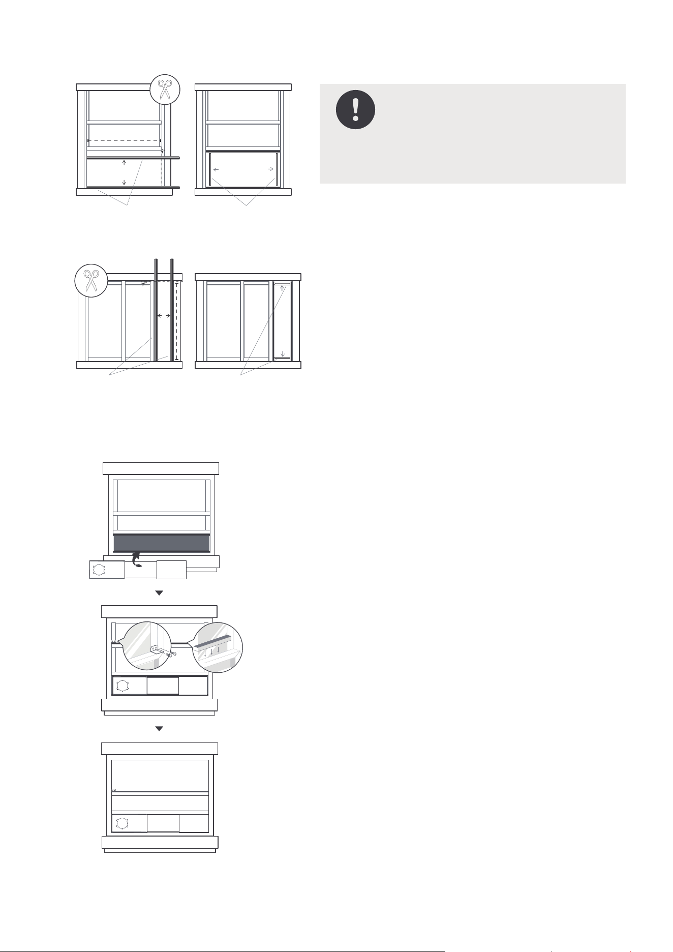
3. Complete sealing of window
4. Hung Window Installation
NOTE: Once the exhaust hose
assembly and adjustable window
slider are prepared, choose one
of the two installation methods
based on the window type.
Insert the window slider assembly into the window
opening.
If desired, install the security bracket with 2 screws as
shown.
Cut the non-adhesive foam seal C strip to match the
width of the window. Insert the seal between the glass
and the window frame to prevent air and insects from
getting into the room.
:2 petS
:1 petS
Step 3:
Foam seal B
(Adhesive type-shorter)
Foam seal A
(Adhesive type)
Foam seal B
(Adhesive type-shorter)
Foam seal A
(Adhesive type)
Hung Window Installation
Sliding Window Installation
Cut the adhesive foam seal A and B strips to the
proper lengths, and attach them to the window
sash and frame as shown.
21
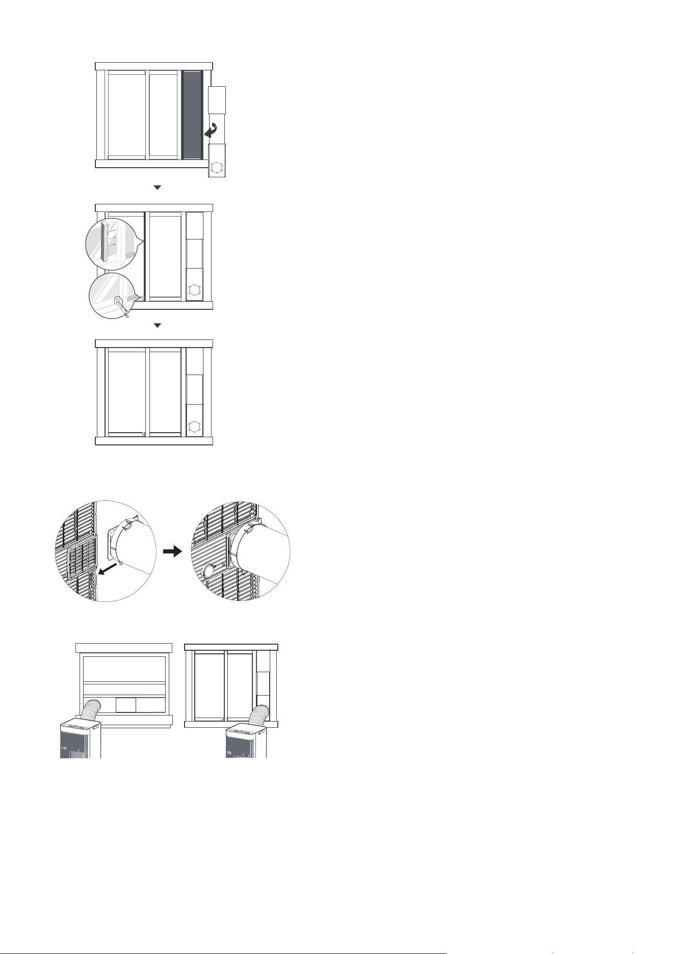
5. Sliding Window Installation
6. Install the exhaust hose assembly to the unit
7. Connect the adaptor to the unit and the window
Push the exhaust hose into the air outlet opening
of the unit along the arrow direction.
Insert the window slider adapter into the hole of the
window slider.
Hung Window Installation Sliding Window Installation
Insert the window slider assembly into the window
opening.
If desired, install the security bracket with 2 screws as
shown.
Cut the non-adhesive foam seal C strip to match the
height of the window. Insert the seal between the glass
and the window frame to prevent air and insects from
getting into the room.
:2 petS
:1 petS
Step 3:
22
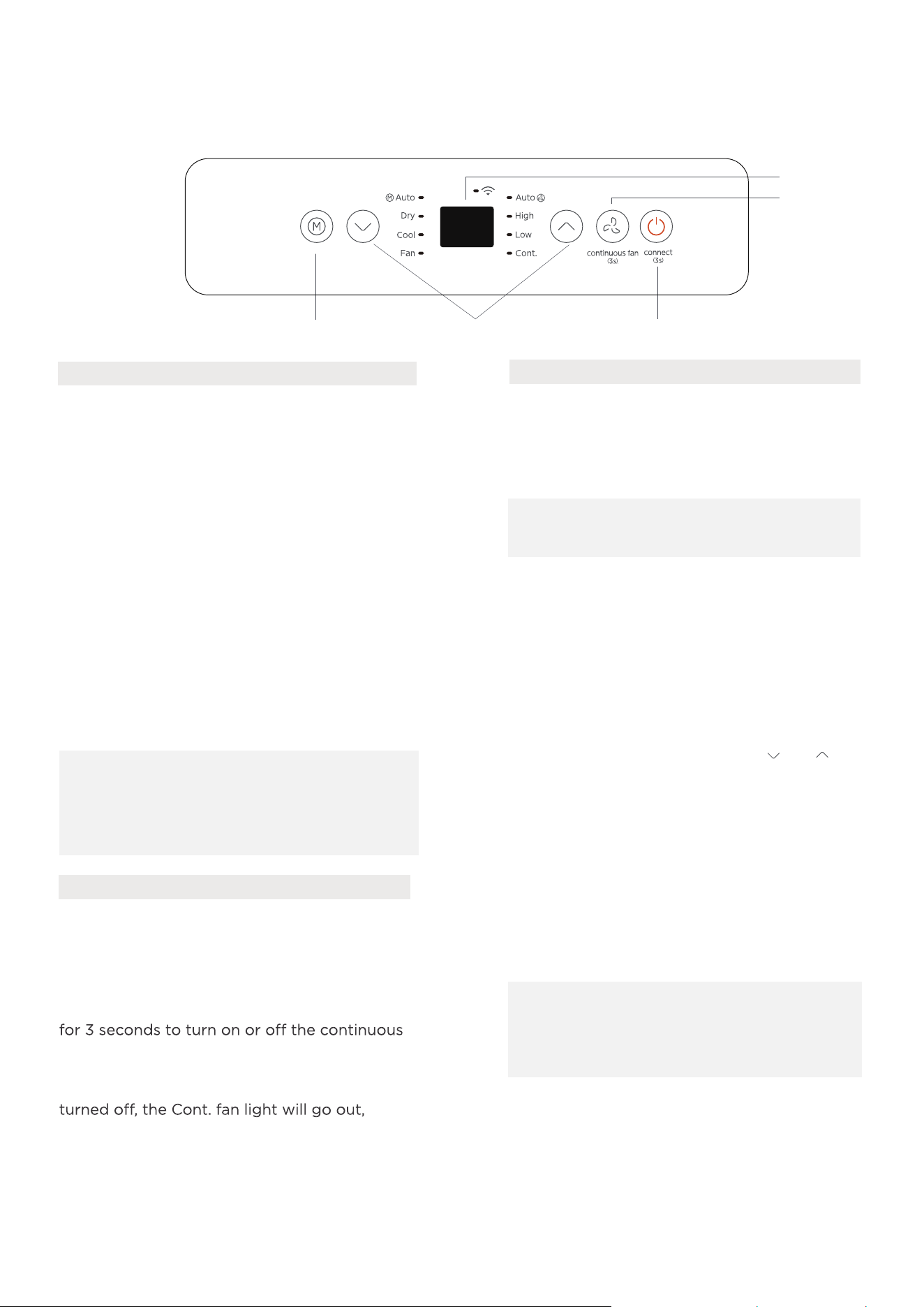
OPERATION INSTRUCTIONS
Electronic control operating instructions
1. POWER button
Power switch on/o.
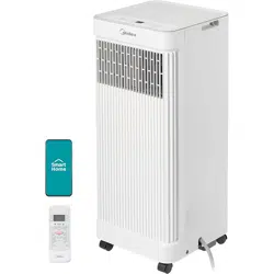
Activate wireless operation(on some models).
•
•
NOTE:
Upon restarting the wireless
function, it may take some time for the
device to automatically connect to the
network.
For the first time using the wireless function,
press the POWER button for 3 seconds to
initiate the wireless connection mode. The LED
display indicates 'AP' to signal that the wireless
connection can be set. If the connection to the
router is successful within 8 minutes, the
wireless indicator will illuminate. If connection
fails within 8 minutes, the unit exits wireless
connection mode automatically. After wireless
connection is successful, for some models press
MODE and UP(+) buttons at the same time for
3 seconds to turn o Wireless function and the
LED DISPLAY shows 'OF' for 3 seconds, press
MODE button and UP(+) to turn on Wireless
function and the LED DISPLAY shows 'On' for
3 seconds.
Continuous Fan function
In COOL or DRY mode, press the Fan button
fan function. When the function is turned on,
the Cont. fan light will illuminate, indicating the
fan will run continuously. When the function is
indicating that the fan will stop when the
compressor stops.
2. FAN button
Press to control the fan speed in AUTO, HIGH,
LOW, or CONT. The fan speed indicator
illuminates under dierent fan settings.
3. MODE button
Select the appropriate operating mode. Each
time the button is pressed, the modes are
selected in the order of AUTO, DRY, COOL
and FAN. The dierent mode indicators
illuminate at dierent mode settings.
NOTE: In AUTO mode, the FAN
speed will be adjusted automatically.
Press the "MODE" button until the "Dry"
indicator lights up. In this mode, the fan speed
or the temperature cannot be adjusted. The
fan motor operates at Auto speed.
DRY mode
Press the "MODE" button until the "Auto"
indicator lights up. In this mode, the fan
speed or the temperature will be adjusted
automatically.
AUTO mode
NOTE:
Keep windows and doors
closed for the best dehumidifying
eect. Do not put the duct against
window.
The temperature can be set within a range of
16°C~30°C/60°F~86°F.
Press the "FAN " button to choose the fan speed.
COOL mode
Press the "MODE" button until the "COOL"
indicator lights up.
Press the UP and DOWN buttons " " or " "
to select the desired room temperature.
2. FAN
5. Display
1. POWER3. MODE
4. UP and DOWN
23
FAN mode
Press the "MODE" button until the "FAN" indicator lights up.
Press the "FAN SPEED" button on the remote controller to choose the fan speed. The temperature can
not be adjusted.
Do not put the duct against window.
4. UP and DOWN buttons
Adjust (increasing/decreasing) temperature settings in 1°C/2°F (or 1°F) increments in a range of
16°C/60°F to 30°C/88°F (or 86°F).
NOTE: The control is capable of displaying temperature in degrees Fahrenheit or
degrees Celsius. To convert from one to the other, press and hold the Up and Down
buttons at the same time for 3 seconds.
5. Display
COMFORTSENSE feature (On some models)
This feature can be activated from the remote control ONLY and there is no indicator light on the control
panel.
The remote control serves as a remote thermostat allowing for the precise temperature control at its
location.
To activate the ComfortSense feature, point the remote control towards the unit and press the
ComfortSense button.
If the unit does not receive the ComfortSense signal during any 7 minutes interval, the unit will exit the
ComfortSense mode.
NOTICE: This feature is unavailable under FAN or DRY mode.
6. Other features
It shows the set temperature in Cool or Auto mode while showing the room temperature in DRY or
FAN mode.
Shows Error codes:
EH00-EEPROM error.
EH60-Room temperature sensor error.
EH61-Evaporator temperature sensor error.
EC52-Condenser temperature sensor error (on some models).
EH0b-Display panel communication error.
EC-Refrigerant leakage detection malfunction(on some models).
Shows protection code:
P1-Bottom tray is full--Connect the drain hose to drain the water collected. If protection repeats, call
for service.
NOTE:
and unplug the power cord. Contact the manufacturer, its service agents or a similar
qualified person for service.
24
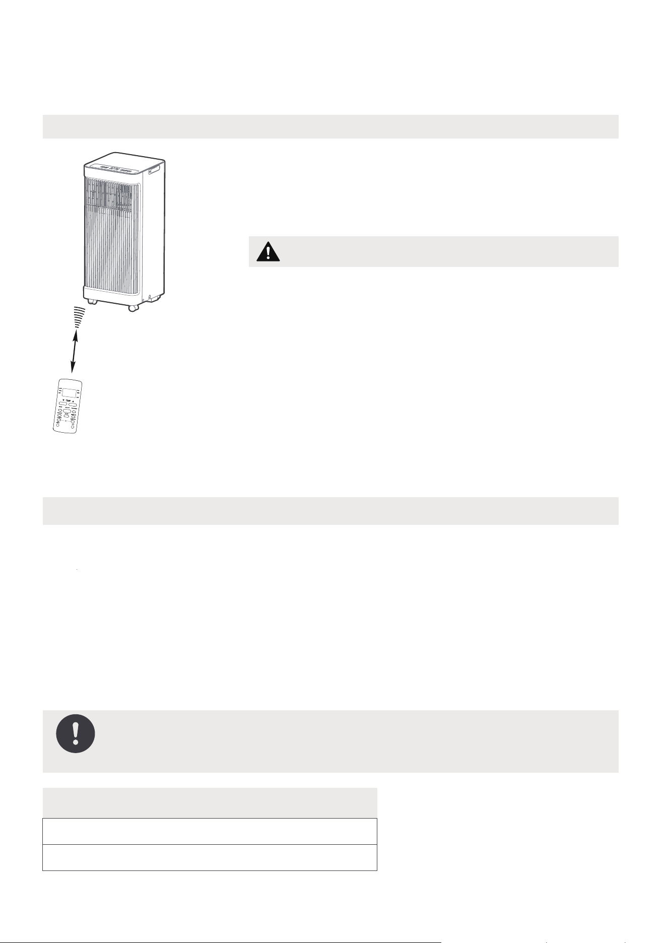
REMOTE CONTROL INSTRUCTIONS
Location of the remote control
Use the remote controller within a distance of 26.2 ft
(8 meters) from the air conditioner, pointing it towards
the receiver. Reception is confirmed by a beep.
Handling the Remote Control
•
The air conditioner will not operate if curtains,
doors or other materials block the signals from the
remote control to the unit.
•
Prevent any liquids from spilling onto the remote
control. Do not expose the remote control to
direct sunlight or heat.
•
If the infrared signal receiver on the indoor unit is
exposed to direct sunlight, the air conditioner may
not function properly.
•
If other electrical appliances react to the remote
control, either
move these appliances or consult
the local dealer.
CAUTION
26.2 ft (8 meters)
NOTICE
•
The button design is based on a typical model and may vary slightly from the
actual product purchased.
•
All of the features listed in "Operating Instructions" can be operated using the
buttons on the control panel of the unit. If there is a feature listed in the "Operating
Instructions" that does not appear on the unit's control panel, then the unit does
not have that feature. If the remote control has a button for the missing feature, the
unit will still not respond when the button on the remote is pressed.
•
When there are significant dierences between features or operation
demonstrated by the remote control and the actual functions described in the
USER MANUAL, the descriptions in the USER MANUAL should be followed.
Remote Controller Specifications
Rated Voltage: 3.0V (Dry batteries R03/LR03x2)
Environment:
NOTE: Some features such as ComfortSense, Timer, and Sleep Mode are
only available using the remote control. There will be no corresponding
button for these features on the control panel.
25
23°F~140°F (-5°C~60°C)
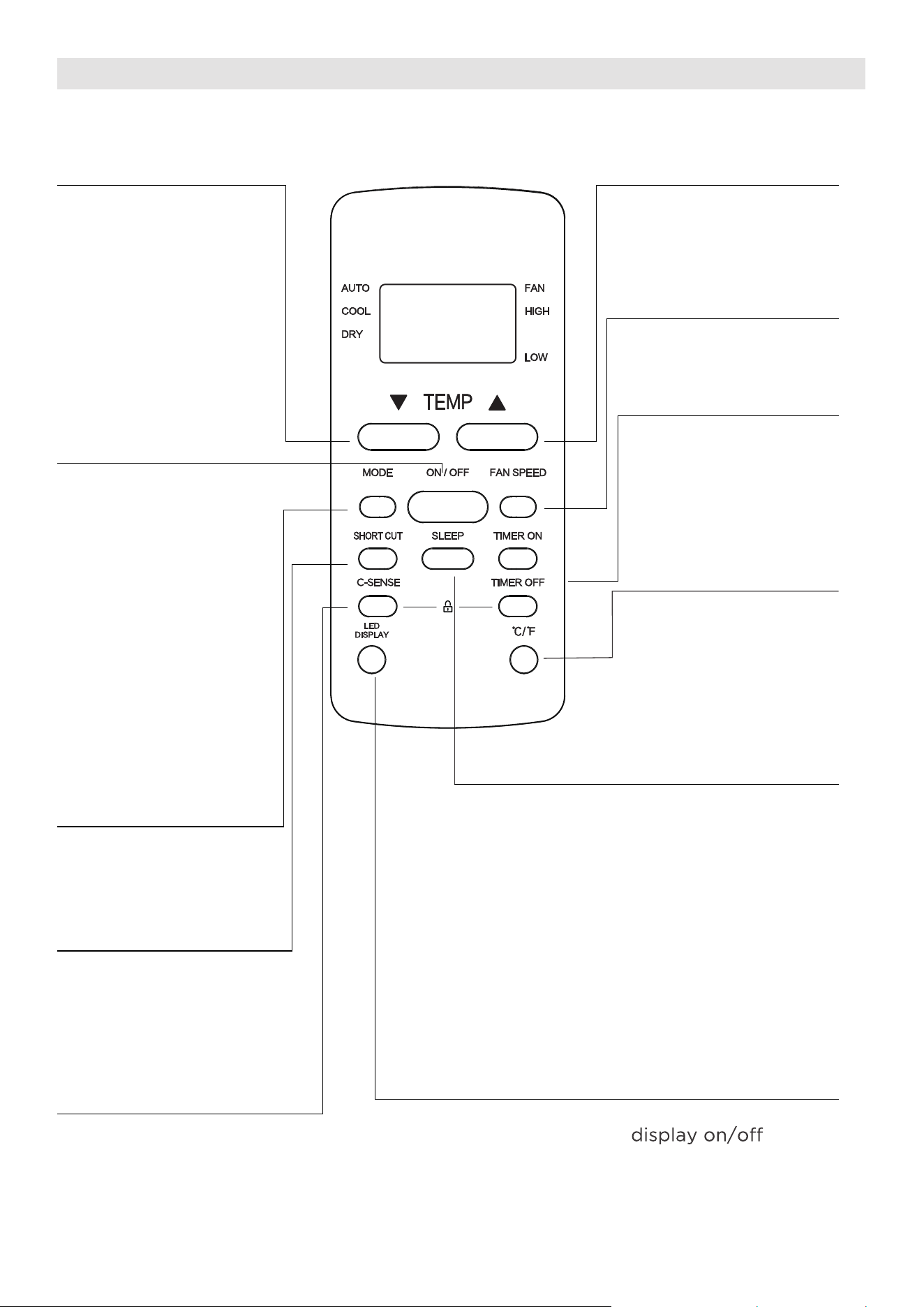
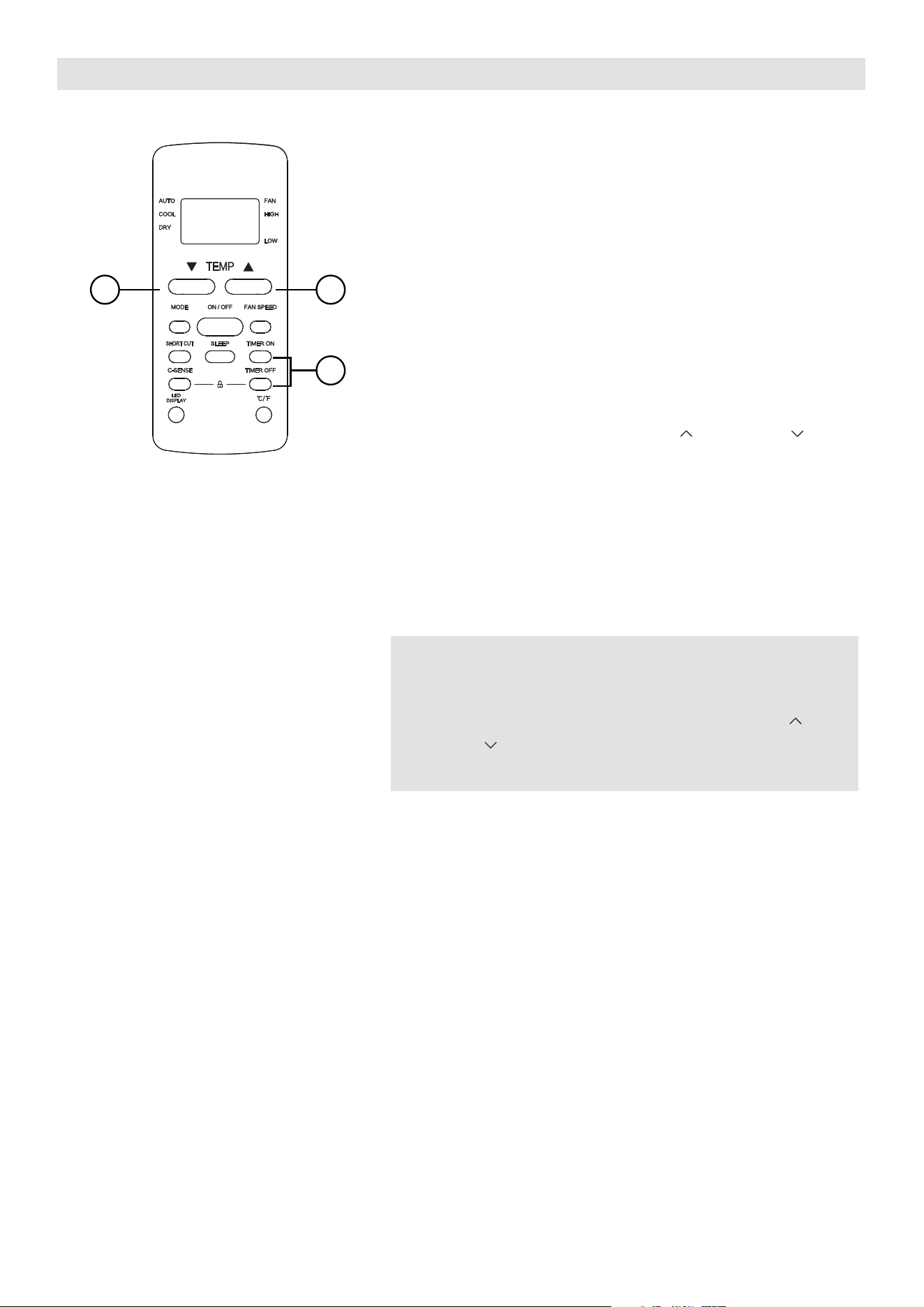
Function Buttons
MODE Button
Press this button to
select the desired
operation mode.
TEMP UP Button
Press this button to
increase the indoor
temperature setting.
SPEED Button
Select the desired
fan speed.
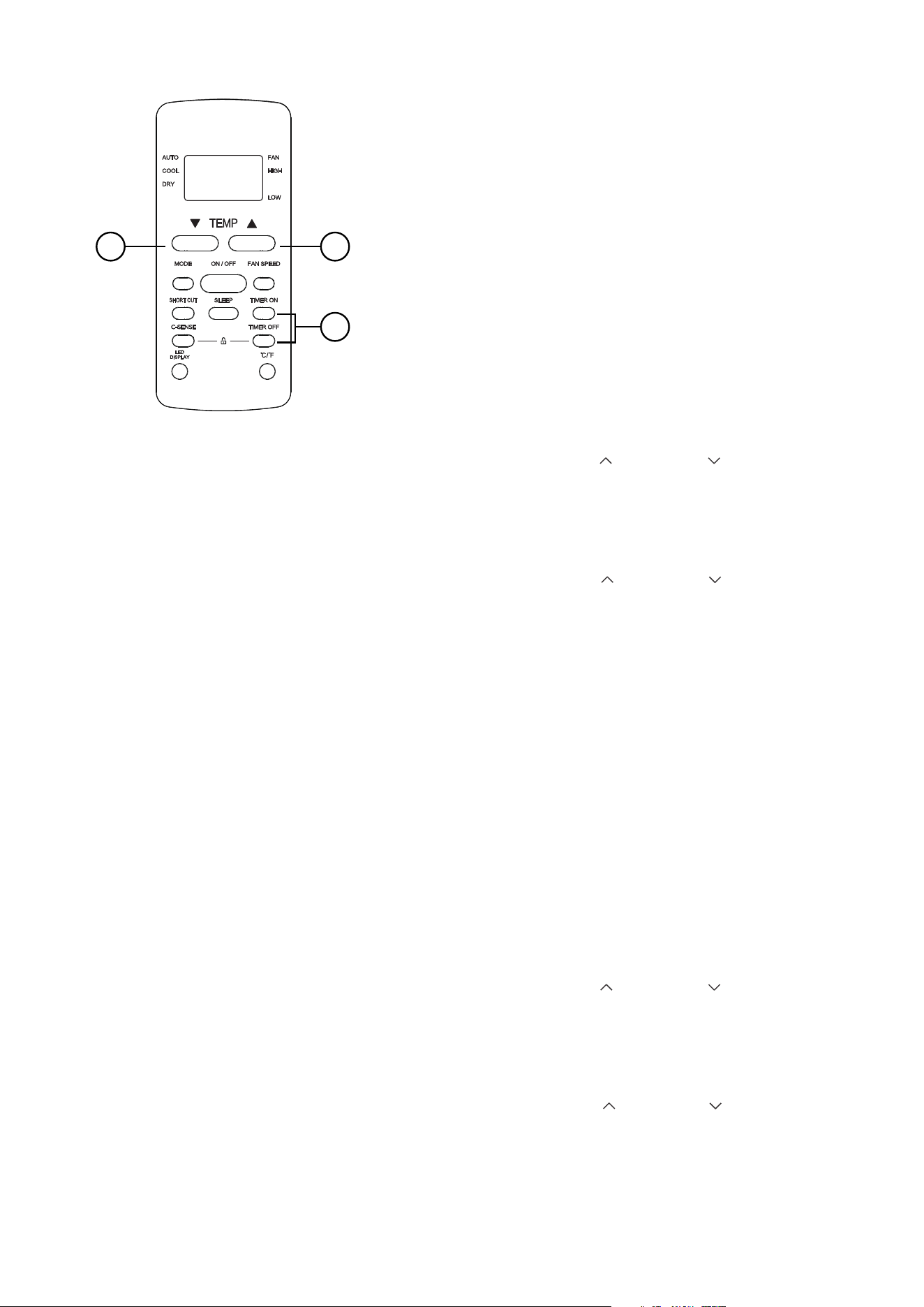
SLEEP Button
Press this button to
activate Sleep mode.
This function is available
in COOL or AUTO mode
only, maintaining optimal
comfort while saving
energy.
LED DISPLAY Button
Turn the unit’s LED
°C/°F Button
Press this button to
change the temperature
display between Celsius
and Fahrenheit
TEMP DOWN Button
Press this button to
decrease the indoor
temperature setting.
TIMER Button
Press this button to
activate the “Auto
Start” or “Auto Stop”
program.
ON/OFF Button
Operation starts when
this button is pressed
and stops when the
button is pressed again.
Set and activate
favorite pre-settings.
COMFORTSENSE Button
Press this button to activate
ComfortSense mode,
optimizing the temperature
in your surroundings to
ensure maximum comfort.
SHORT CUT Button
26
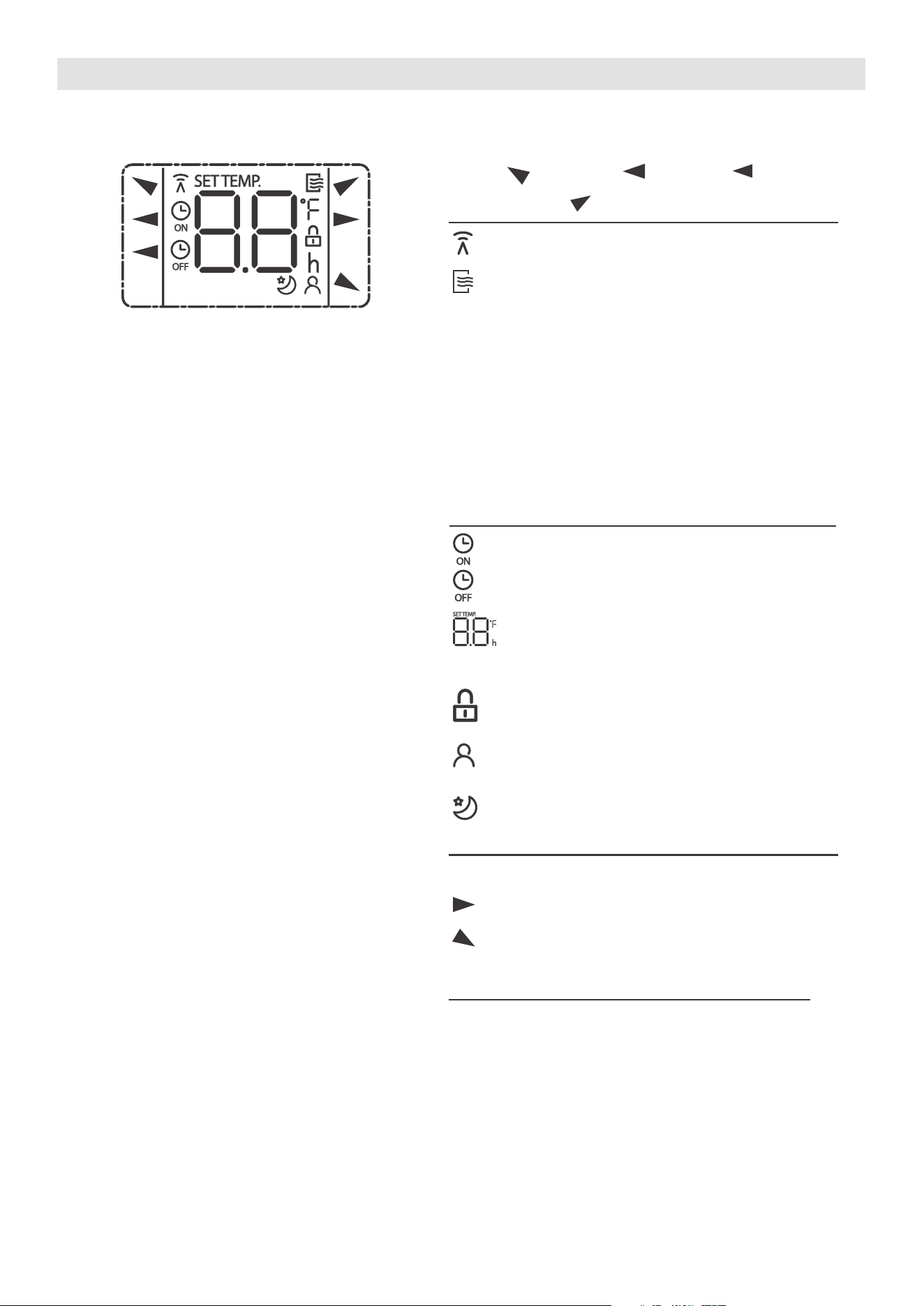
Information is displayed when the remote controller is powered up.
All indicators shown in the figure are intended to be clear.
But during the actual operation, only the relative function signs are shown on the
display.
Remote Screen Indicators
Displayed when data transmitted.
The indicator displays when the
remote is enabled and can send
signals to the unit. To turn o the
remote without aecting the unit,
point it away and press the ON/OFF
button. To turn the remote back on,
repeat the same action. If this
indicator is not illuminated, the unit
will not receive commands from
the remote.
AUTO
COOL
DRY
AUTO
COOL
FAN
DRY
Mode display
FAN
HIGH
LOW
Low speed
NO display
High speed
Auto fan speed
Displayed when TIMER ON time is set
Displayed when TIMER OFF time is set
Indicates all the current settings are
locked
Shows set temperature or room
temperature, or time under TIMER
setting
HIGH
LOW
Fan speed indication
Displayed when ComfortSense
feature is activated(on some models)
Displayed when SLEEP feature is
activated
Note:
27
How to Use the Buttons
TIMER OPERATION
Press the TIMER button to initiate the Auto-start
and Auto-stop setting program of the unit.
To set the Auto-start/stop time.
1. Press the TIMER button, when the TIMER ON
indicator is displayed on the LED window of
the air conditioner, it indicates the Auto Start
setting program is initiated. When the TIMER
OFF indicator is displayed on the LED window
of the air conditioner, it indicates the Auto
Stop setting program is initiated.
2. Press or hold the TEMP UP ( )/DOWN ( ) to
change the Auto time. The control will c
ount
down the time remaining until start/stop.
3. The selected time will register in 5 seconds and
the air conditioner will automatically revert back
to display the previous temperature setting.
4. Turning the unit ON or OFF at any time will
cancel the Auto Start/stop function.
NOTES
To cancel the TIMER setting, push the TIMER
button and press or hold the TEMP UP ( )/
DOWN ( ) until 0 hour is displayed on the LED
window of the air conditioner.
1
22
28
COMBINED TIMER
(Set both ON and OFF timers simultaneously)
AUTO STOP > AUTO START
(On > Stop > Start operation)
This feature is useful for stopping the air
conditioner after going to bed and restarting
it in the morning or when returning home.
Example:
To stop the air conditioner 2 hours after setting
and start it again 10 hours after setting.
AUTO START > AUTO STOP
(Off > Start > Stop operation)
This feature is beneficial for starting the air
conditioner before waking up and stopping it
after leaving the house.
Example:
To start the air conditioner 5 hours after setting,
and stop it 8 hours after setting.
1
22
1. Press the TIMER button until the TIMER OFF
indicator is displayed on the LED display of
the air conditioner.
2. Use the TEMP UP ( )/DOWN ( ) button to
display “2.0” on the LED display of the air
conditioner.
3. Press the TIMER button again to display the
TIMER OFF on the LED display of the unit.
4. Use the TEMP UP ( )/DOWN ( ) button to
display “10” on the LED display of the unit.
5. Wait for 5 seconds until the previous display
ap
pears in LED window.
1. Press the TIMER button until the TIMER ON
indicator is displayed on the LED display of
the air conditioner.
2. Use the TEMP UP ( )/DOWN ( ) button to
display “5.0” on the LED display of the air
conditioner.
3. Press the TIMER button again to display the
TIMER OFF on the LED display of the unit.
4. Use the TEMP UP ( )/DOWN ( ) button to
display “8.0” on the LED display of the unit.
5. Wait for 5 seconds until
the previous display
appears in LED window.
29

Timer Functions
The unit has two timer-related functions:
TIMER ON - set the time for the device to turn on
automatically.
TIMER OFF - set the time for the device to turn off
automatically.
TIMER ON function
The TIMER ON function enables the user to set a specific
period after which the unit will automatically turn on, such
as when returning home from work.
1. Press the TIMER ON button. The display will show the
last set time period, along with an "h" to indicate hours.
2sec
ON/OFF
MODE
FAN
SHORT
CUT
TIMER ON
TIMER OF
F
TEMP
S
L
E
EP
1sec
x5
1
3
2
4
TIMER ON TIMER ON
Example: Set unit to turn
on after 2.5 hours.
2sec
x10
ON/OFF
MODE
F
AN
SHORT
CUT
TIMER ON
TIMER OF
F
TEMP
S
L
EEP
1sec
1
3
2
4
TIMER OFF
TIMER OFF
NOTICE
This number indicates the duration for which the device
will remain on after the current time.
For example, if TIMER ON is set for 2 hours, "2.0h" will
display, and the unit will turn on after 2 hours.
NOTICE
This number indicates the duration for which the device
will remain on after the current time.
For example, if TIMER ON is set for 2 hours, "2.0h" will
display, and the unit will turn on after 2 hours.
2. Press the TIMER ON button repeatedly to set the desired
duration for the unit to turn on after the current time.
3. Wait 2 seconds, then the TIMER ON function will be
activated. The digital display on the remote control will
then return to the temperature display.
TIMER OFF function
The TIMER OFF function allows you to set a specific duration
after which the unit will automatically turn off, such as when
waking up.
1. Press the TIMER OFF button. The display will show the
last set time period along with an "h" to indicate hours.
2. Press the TIMER OFF button repeatedly to set the desired
duration for the unit to turn off after the current time.
Example: Set unit to turn
off after 5 hours.
30
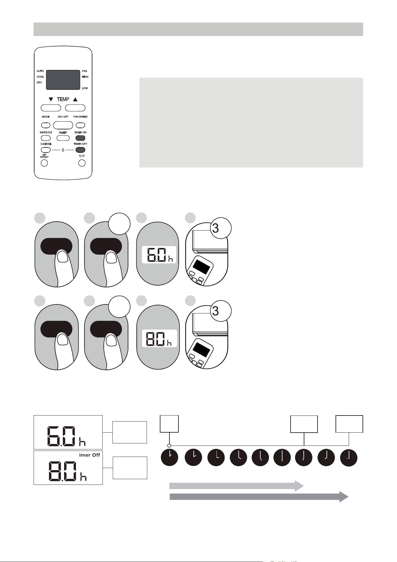
NOTE
When setting the TIMER ON or TIMER OFF functions,
the time can be adjusted up to 10 hours in 30-minute
increments with each press. After 10 hours, increments
change to 1 hour up to a maximum of 24 hours. The
timer will reset to zero after 24 hours. Either function
can be turned off by setting the timer to "0.0h."
3. Wait 2 seconds, then the TIMER OFF function will be
activated. The digital display on the remote control will
then return to the temperature display.
Continue
to press
TIMER ON
or
TIMER OFF
until desired
time is
reached.
ON/OFF
MODE
SHORT
CU
T
TIMER ON
TEMP
sec
4
ON/OFF
MODE
SHORT
C
U
T
TIMER ON
TEMP
sec
8
1
TIMER ON
X12
2
TIMER ON
5
TIMER OFF
X16
6
TIMER OFF
3
7
Setting both TIMER ON and
TIMER OFF at the same time
Note that the time periods set
for both functions refer to the
hours following the current time.
For example, if the current time
is 1:00 PM and the unit is set to
turn on automatically at 7:00 PM
and operate for 2 hours, it will
turn off automatically at 9:00 PM.
Do the following (side figure):
Example: Set the unit to turn on after 6 hours, operate for 2 hours, then turn off
(see the figure below)
Timer On
T
Timer is set
to turn ON
6 hours after
current time
Timer is set
to turn OFF
8 hours after
current time
Current
Time 1PM
2PM 3PM
4PM 5PM
6PM 7PM 8PM 9PM
Unit turns
ON
Unit turns
OFF
6 hours later
8 hours later
Timer
Starts
Remote display
Timer Functions (cont.)
T i m e r on
31
NOTES
• Button design is based on a typical model and may slightly vary from the actual
one purchased.
• This device complies with part 15 of the FCC Rules. Operation is subject to the
following two conditions: (1) This device may not cause harmful interference,
and (2) this device must accept any interference received, including interference
that may cause undesired operation.
•
This equipment has been tested and found to comply with the limits for a Class
B digital device, pursuant to part 15 of the FCC Rules.
These limits are designed
to provide reasonable protection against harmful interference in a residential
installation. This equipment generates, uses and can radiate radio frequency
energy and, if not installed and used in accordance with the instructions, may cause
harmful interference to radio communications. However, there is no guarantee that
interference will not occur in a particular installation.
If this equipment does cause
harmful interference to radio or television reception, which can be determined by
interference by one or more of the following measures:
- Reorient or relocate the receiving antenna.
- Increase the separation between the equipment and receiver.
receiver is connected.
- Consult the dealer or an experienced radio/TV technician for help.
- Changes or modifications not approved by the party responsible for compliance
could void users authority to operate the equipment.
Battery Warning:
Do not mix old and new batteries and Do not mix alkaline, standard (carbon-zinc)
or rechargeable (ni-cad, ni-mh, etc.) batteries
Unique Identifier: Midea brand,RG51H2(2)/CEFU1-M
Responsible Party U.S. Contact
Information
Midea America Corporation
300 Kimball Dr
Parsippany NJ
07054
This device complies with Part 15 of the FCC Rules. Operation is subject to the
following two conditions: (1) This device may not cause harmful interference, and
(2) this device must accept any interference received, including interference that
may cause undesired operation.
Telephone number or internet contact information: Midea.com/us
FCC Compliance Statement ( products subject to Part 15)
Supplier's Declaration of Conformity
47 CFR § 2.1077 Compliance Information
32

APP INSTRUCTIONS
Specification of Wireless Module
Operation Temperature: 0°C ~ 45°C / 32°F ~ 113°FWireless Module Model: US-SK109
Operation Humidity: 10% ~ 85%Antenna Type: Printed PCB Antenna
Power Input: DC 5V / 500 mAFrequency Band: 2400 - 2483.5MHz
Maximum TX Power: < 20dBm
Precautions
1. Supports operating systems: iOS 10+ or Android 5+.
2. In the event of an iOS update, there may be a delay before a related software update becomes available,
during which the iOS may or may not be supported until a new version is released. Compatibility issues or
network problems with specific mobile devices may prevent the system from functioning properly, and
Midea will not be responsible for any resulting issues.
3. This Smart AC only supports WPA-PSK/WPA2-PSK (recommended) encryption.
4. To ensure proper scanning of the QR code, the smart phone must have at least a 5-megapixel camera.
5. Due to unstable network connectivity, requests may time out. If this happens, re-run the network
configuration.
6. Due to unstable network connectivity, commands may time out. If this happens, the smartphone app and
the actual product may display conflicting. The information displayed on the actual product is always the
most accurate available. Refresh the app to re-sync.
Midea will not be responsible for any problems that could be caused by incompatibility or network issues, the
wireless router and mobile phone.
NOTE
33
1. How to Use SmartHome App
Ensure that the mobile phone is connected to the wireless network. Bluetooth must be turned on.
The device must also be powered up.
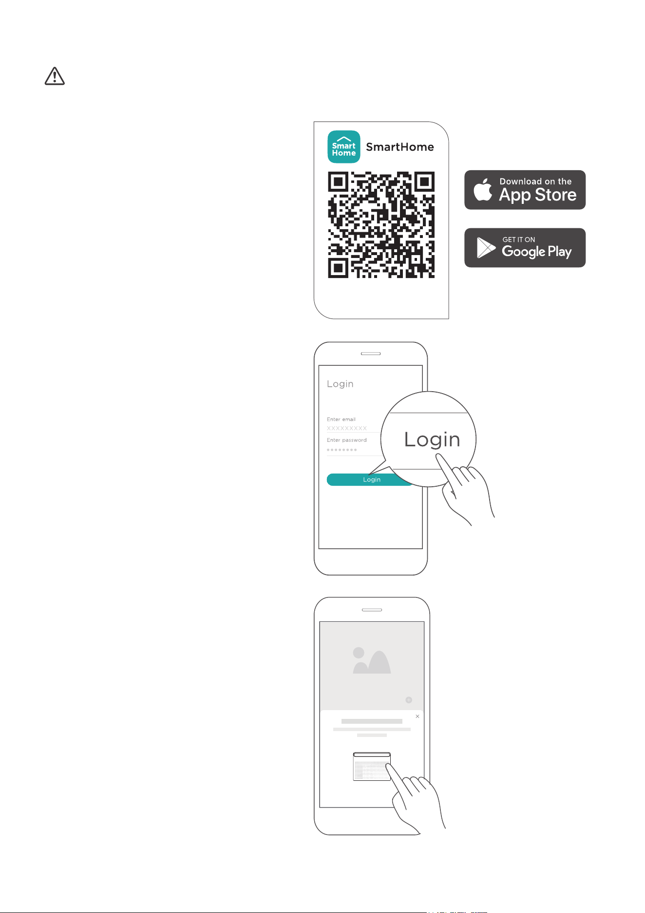
STEP 1: Download the SmartHome App
Scan the QR code below to download the
SmartHome app from the app store or search for
it directly on the Google Play Store or Apple’s
App Store.
STEP 2: Log in
Open the SmartHome app. Log in directly
with an existing SmartHome account or
create a new account. Alternatively, a
third-party login platform can also be
used.
STEP 3: Connecting the Device
1) Upon logging in, a message may appear
stating "Smart devices discovered nearby."
Tap to add the device.
Download the app
& activate product
34
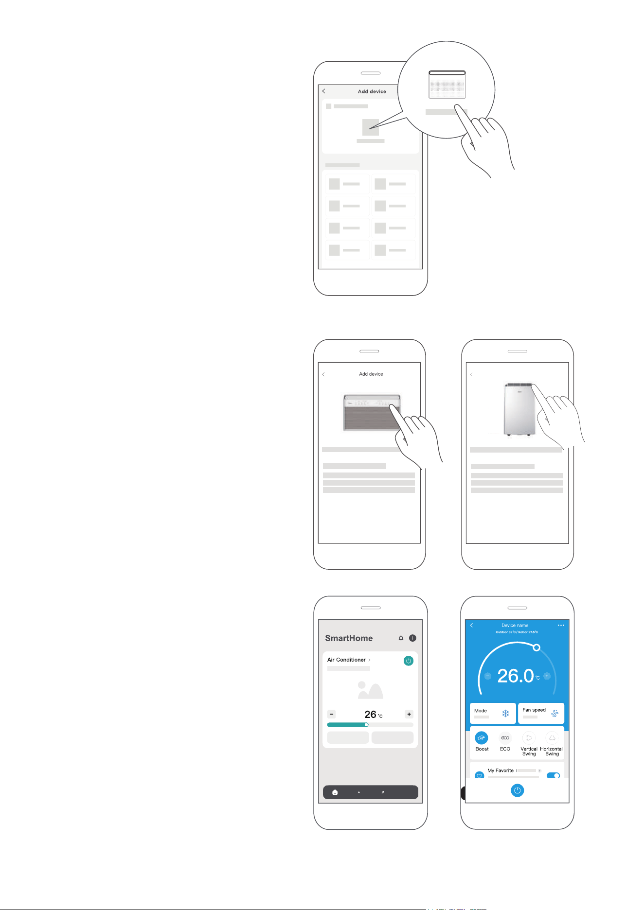
2) If no message appears, tap the “+” icon
and select the device from the list of
nearby available devices. If the device
is not listed, add it manually by first
selecting the device category (i.e.
Window AC).
3) Follow the steps in the app to connect
the device to the wireless network. If
the connection fails, refer to the
additional instructions provided in
the app.
STEP 4: Controlling the Device
After pairing successfully, a card (Fig. 1) will be
created for the device in the SmartHome app.
Fig. 1
Shortcuts for basic functions will appear on
the card, such as changing the temperature or
switching the device on or o.
Tapping on the card will reveal additional
features and settings. The actual UI design may
look dierent from examples due to app updates.
For Window AC For Portable AC
Add device
35
2. How to Use Matter
Matter is a connectivity technology that unifies the smart home by allowing devices and ecosystems (such
as Alexa, Google Home and Apple Home) to speak the same language thus creating exciting new features
and use cases.
To use Matter, at least one Matter-enabled smart speaker from Amazon, Google, or Apple is required, along with
the appropriate app.
• If a Matter-enabled smart speaker is available, please proceed to the "How to Use Matter" instructions on
the following pages.
• If a Matter-enabled smart speaker is not available, Matter cannot be used at this time. However, full
functionality of the product can still be achieved using the SmartHome app. Please refer to the "How to
Use SmartHome App" section on pages 34-35.
Connect the air conditioner through Matter
Make sure the mobile device is connected to the correct wireless router.
Wireless router should support and turn on IPv6. Please make sure the smartphone connect to 2.4G
but not 5G network.
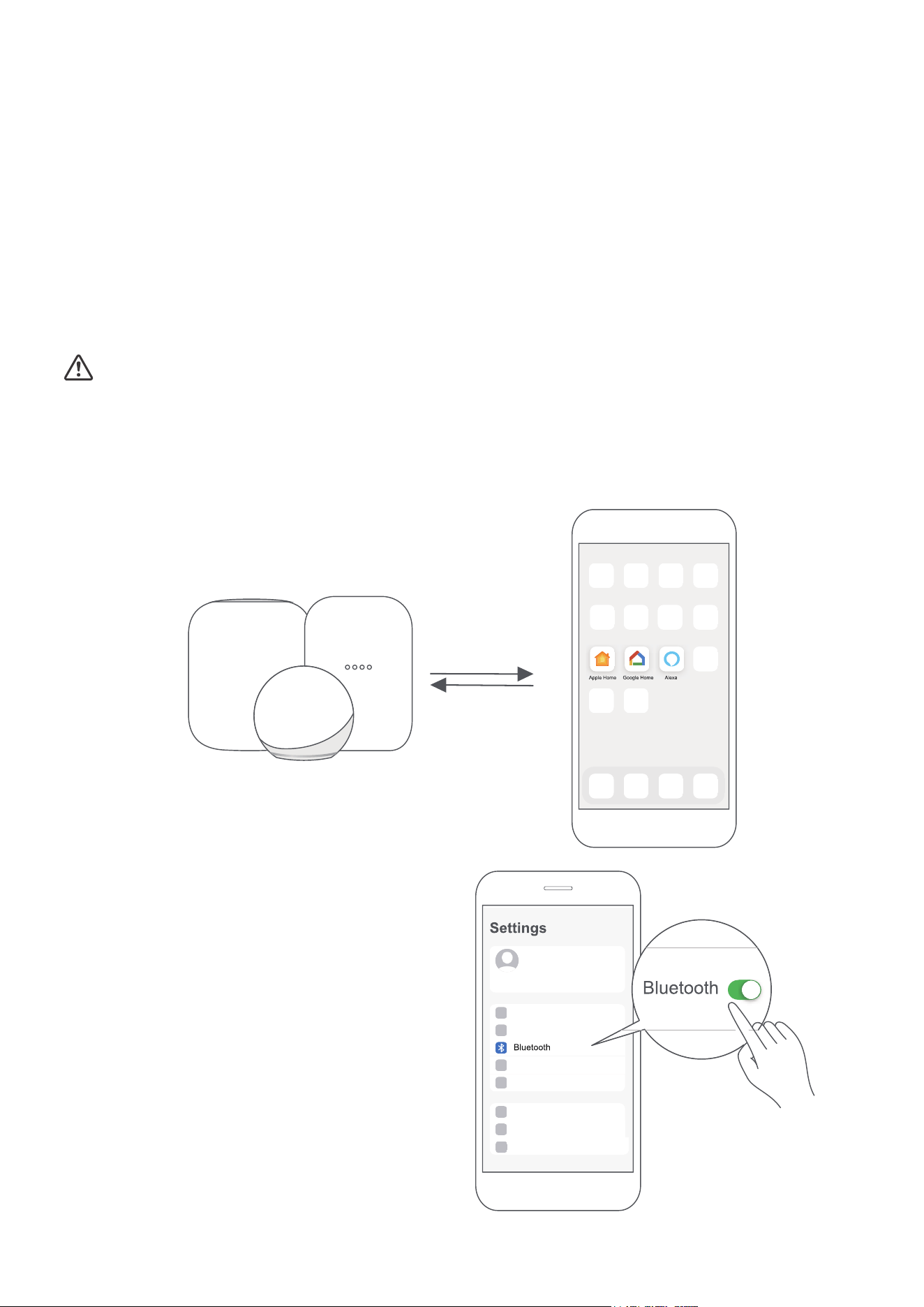
STEP 1: Connect to Smart Speakers
Select the preferred ecosystems (Alexa, Google Home or Apple Home) and ensure that at least one
Matter-enabled product, such as a smart speaker, is connected to the wireless router.
STEP 2: Turn On Bluetooth
Turn on Bluetooth on the mobile device.
36
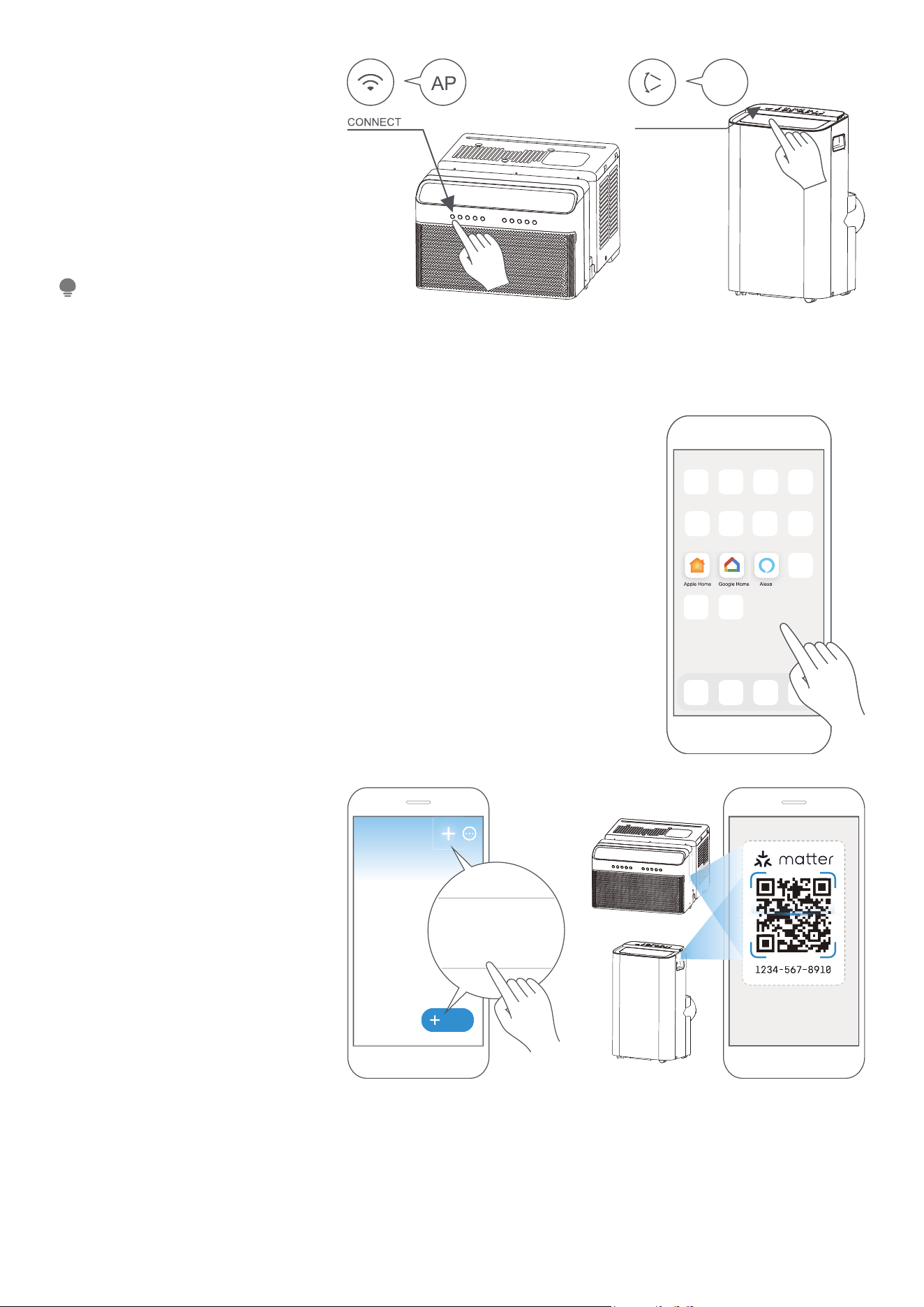
STEP 3: Enter AP Mode
Windows AC: Hold down the
CONNECT / Power button for
3 seconds to begin the pairing
process (“AP” will appear on the
AC’s display).
Portable AC: Hold down the SWING
/ Power button for 3 seconds to
begin the pairing process (“AP” will
appear on the AC’s display).
STEP 4: Open App
Open the Alexa, Google Home or Apple Home app on the mobile device.
Window AC
AP
SWING
Portable AC
Entering AP pairing mode may
vary between dierent AC models,
please follow the instructions of
the AC panel.
NOTE
Add
Add Device/Accessory
scan
Matter QR code
STEP 5: Scan Matter QR code
Tap the “+” and “Add Device/
Accessory” or tap “+Add” in the
app and then select Matter device
and scan the Matter QR code found
on the side of the AC device.
Follow the respective instructions
in the Alexa, Google Home or
Apple Home app to complete the
pairing process.
37
• Setup processes and features may vary between ecosystems.
• The functions shown in the Alexa, Google Home or Apple Home apps may change with updates to their
products or apps.
• Make sure the Matter enabled app is up to date to ensure the best experience.
• Periodically, the device's software will update to improve the experience. Device software updates can be
accomplished through the SmartHome app.
• Use of the Works with Apple badge means that an accessory has been designed to work specifically with the
technology identified in the badge and has been certified by the developer to meet Apple's performance
standards. Apple is not responsible for the operation of this device or its compliance with safety and regulatory
standards.
•
is developed by the Connectivity Standards Alliance TM. This brand, related logos, and marks
are trademarks of the Alliance, all rights reserved.
NOTE
Air conditioner
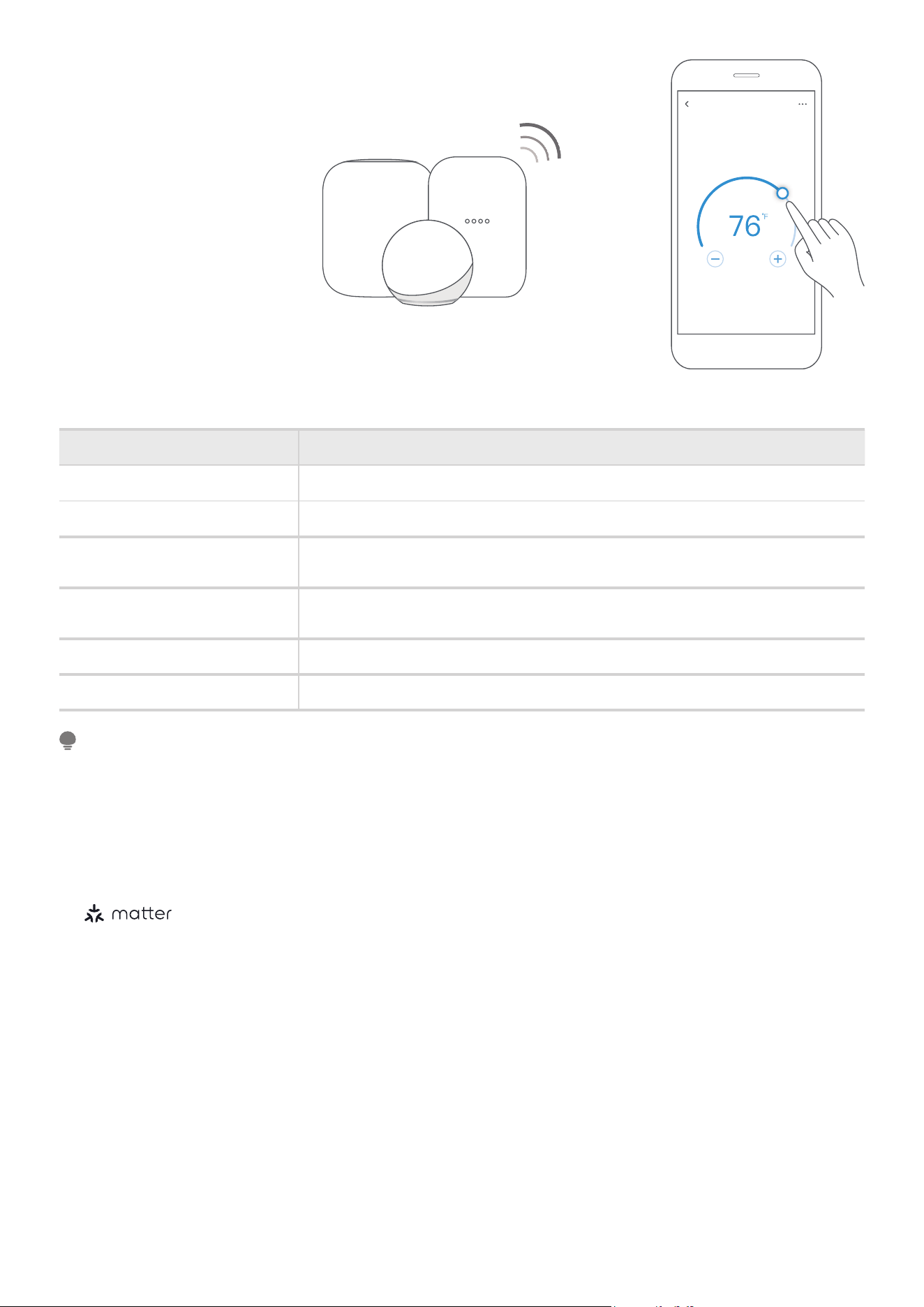
STEP 6: Control Device
After pairing is successful, control
the AC's temperature, mode
settings, etc. through the respective
ecosystem app and smart speaker.
Due to a compatibility issue, the
temperature value shown in the
Alexa, Google Home or Apple
Home app may be 1 degree
different from that displayed on
the air conditioner. However,
this will not impact the device’s
ability to cool the room.
App & Smart Speakers can support Matter only when using these versions or above.
noisreVeciveD
5.61SOienohPi
5.61doP emoH elppA
Android
Google Play services min version: 22.36.15
Google Home app (GHA) min version: 2.58.24.1 - dogfood
Google Home Hub
Google Hub firmware min version: 1.56.324896
(appears on hub as Chromecast firmware version)
713635.2.2ppA axelA
6559344909eciveD ohcE axelA
38

39
Declaration of Conformity
FCC ID: 2ADQOMDNA23
IC: 12575A-MDNA23
This device complies with Part 15 of the FCC Rules and Industry Canada’s licence exempt RSSs.
Operation is subject to the following two conditions:
(1) This device may not cause interference;
(2) This device must acceptany interference, including interference that may cause undesired operation of
the device.
Only operate the device in accordance with the instructions supplied.
Changes or modifi cations to this unit not expressly approved by the party responsible for compliance could
void the user’s authority to operate the equipm
ent.
This device complies with FCC radiation exposure limits set forth for an uncontrolled environment. In order
to avoid the possibility of exceeding the FCC radio frequency exposure limits, human proximity to the
antenna shall not be less than 20cm (8 inches) during normal operation.
This equipment has been tested and found to comply with the limits for a Class B digital device, pursuant to part
15 of the FCC Rules. These limits are designed to provide reasonable protection against harmful interference in a
residential installation.
This equipment generates, uses and can radiate radio frequency energy and, if not installed and used in
accordance with the instructions, may cause harmful interference to radio communications. However, there is
no guarantee that interference will not occur in a particular installation. If this equipment does cause harmful
interference to radio or television reception, which can be determined by turning the equipment o and on, the
user is encouraged to try to correct the interference by one or more of the following measures:
• Reorient or relocate the receiving antenna.
• Increase the separation between the equipment and receiver.
• Connect the equipment into an outlet on a circuit dierent from that to which the receiver is connected.
• Consult the dealer or an experienced radio/TV technician for help.
We, hereby declare that this device is in compliance with the relevant provisions of RE Directive 2014/53/EU.
A copy of the full DoC is attached (Europen Union products only).
NOTE
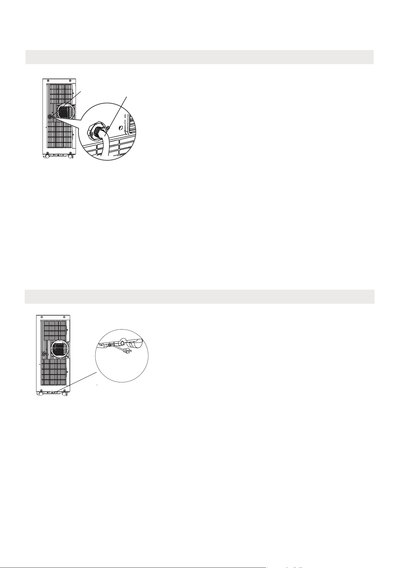
DRAINAGE GUIDE
Remove the
bottom
drain plug
When the water level of the bottom tray reaches a predetermined level,
the unit beeps 8 times, the digital display area shows "P1". At this time
the air conditioning/dehumidification process will immediately stop.
However, the fan motor will continue to operate (this is normal).
Carefully move the unit to a drain location, remove the bottom drain
plug and let the water drain away. Reinstall the bottom drain plug and
restart the machine until the "P1" symbol disappears. If the error repeats,
call for service.
NOTE: Be sure to reinstall the bottom drain plug firmly to prevent
leakage before using the unit.
Water collection tray Drainage Guide
During dehumidifying mode, remove the drain plug from the back of
the unit, install the drain connector (5/8" universal female mender) with
3/4" hose.
Place the open end of the hose directly over the drain area in the basement floor.
NOTE: Make sure the hose is secure so there are no leaks. Direct the
hose toward the drain, making sure that there are no kinks that will
stop the water flowing. Place the end of the hose in
to the drain
and make sure the end of the hose is down to let the water flow
smoothly. Wh
en the continuous drain hose is not used, ensure that the
drain plug is installed firmly to prevent leakage.
Step 1:
Remove the
drain plug
Dehumidifying Mode Drainage Guide
Step 2:
Install the continuous
drain hose
40
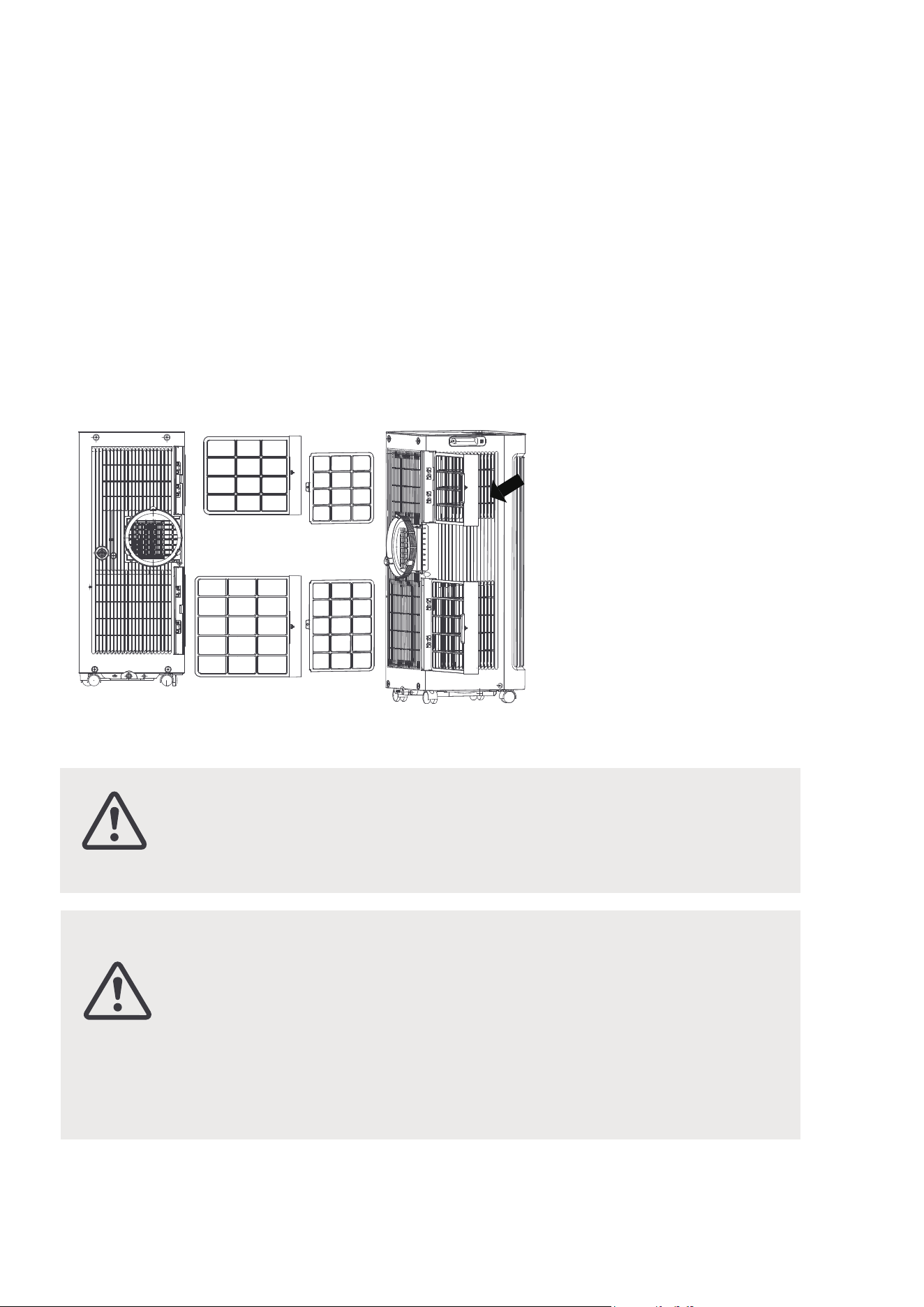
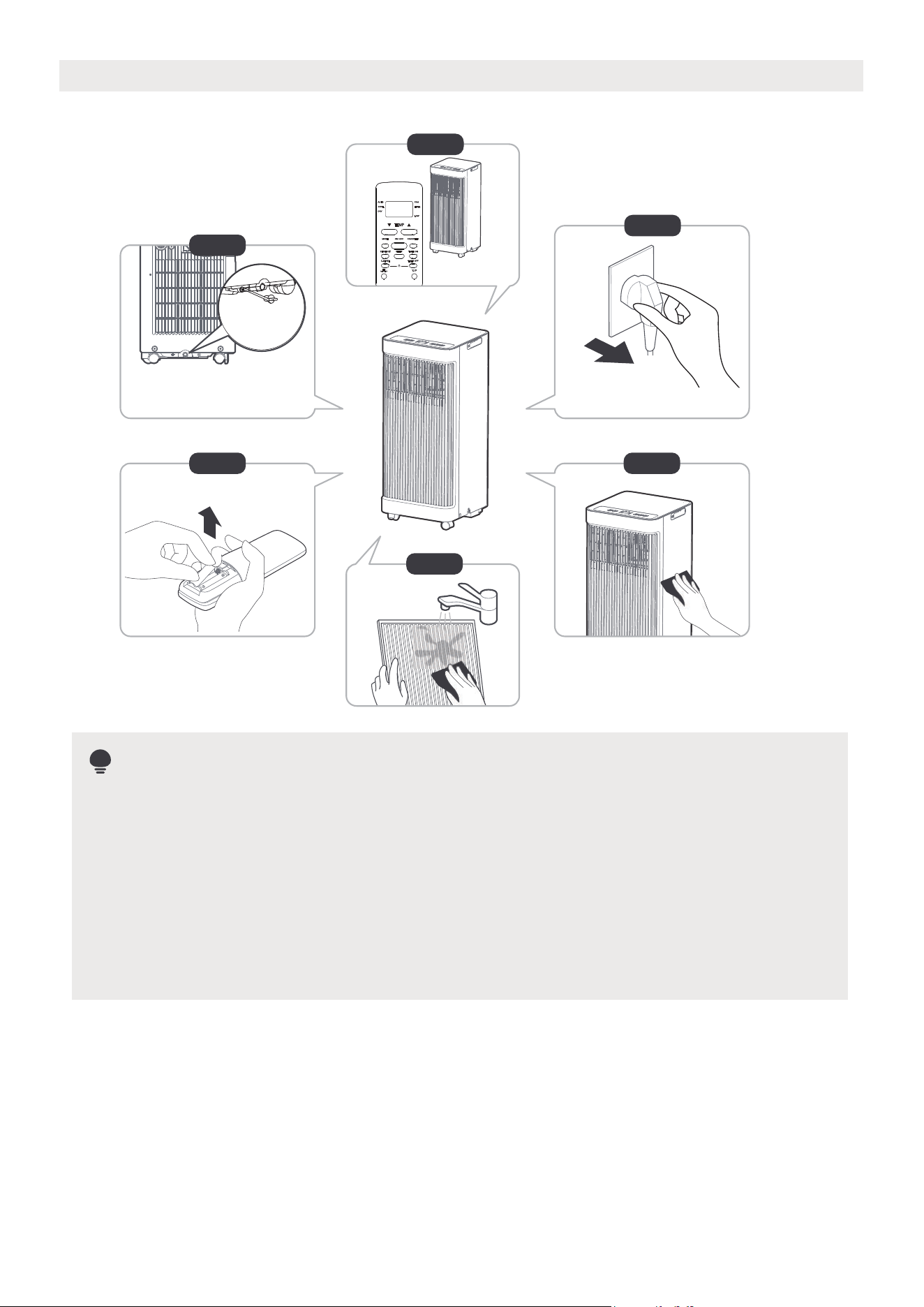
How to clean & maintain the AC.
CLEANING & MAINTENANCE
Air Filter & Cabinet Cleaning
Air filter
(take out)
Remove the air filter
CAUTION:
· Always unplug the unit before cleaning or servicing.
· DO NOT use flammable liquids or chemicals to clean
the unit.
· DO NOT wash the unit under running water. Doing so
causes electrical danger.
· DO NOT operate the machine if the power supply was
damaged during cleaning. A damaged power cord must
be replaced with a new cord from the manufacturer.
CAUTION:
DO NOT operate the unit without filter because dirt and lint will
clog it and reduce performance.
Clean the unit using a damp, lint-free cloth and mild detergent. Dry the
unit with a dry, lint-free cloth.
Maintenance Tips
· Be sure to clean the air filter every 2 weeks for optimal performance.
· The water collection tray should be drained immediately after "P1" error
occurs, and before storage to prevent mold. See Drainage Guide for
instructions on how to properly drain.
· In households with pets, it is important to periodically clean the grille
to prevent airflow blockage from pet hair.
41
Drain the unit’s water collection tray according to the instructions in the drainage guide section.
Run the unit on FAN mode for 12 hours in a warm room to dry it and prevent mold.
Turn o the unit and unplug it.
Clean the unit according to the instructions in the previous section.
Clean the air filters according to the instructions in the previous section. Reinstall the clean
dry filter before storing.
Remove the batteries from the remote control.
Step 1 :
Step 2:
Step 3:
Step 4:
Step 5:
Step 6:
Store the unit when not in use
NOTE
12hours
Be sure to store the unit in a cool, dark place. Exposure to direct sunshine or
extreme heat can shorten the lifespan of the unit.
The cabinet and front may be wiped down with an oil-free cloth or cleaned
with a cloth dampened in a solution of warm water and mild liquid
dishwashing detergent. Rinse thoroughly and wipe dry.
Never use harsh cleanser, wax or polish on the cabinet front.
Be sure to wring excess water from the cloth before wiping around the
controls.
Excess water in or around the controls may cause damage to the unit.
Step 6
Step 3
Step 4
Step 1
Step 2
Step 5
*Please refer to the actual
plug, and the illustration is for
reference only.
*Drain the unit‘s water collection
tray then reinstall the bottom
drain plug back in.
·
·
42
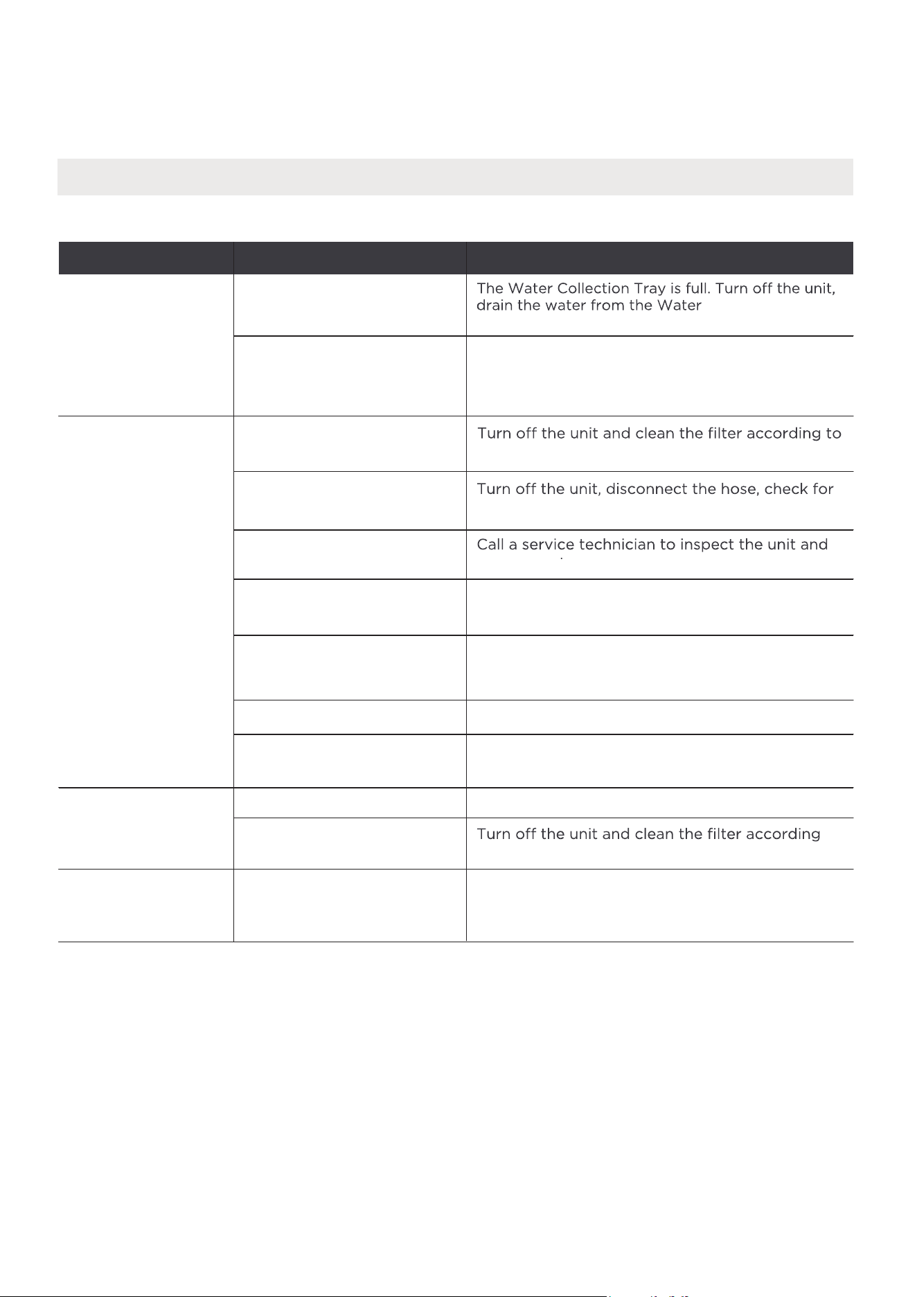
Problem Solving
TROUBLESHOOTING TIPS
Common Issues
The following problems are not a malfunction and in most situations will not require repairs.
noituloSsesuaC elbissoPmelborP
Unit does not turn
on when pressing
ON/OFF button
P1 Protection Code.
In COOL mode: room
temperature is lower than
the set temperature.
Check the set temperature.
instructions.
blockage and reconnect the hose.
top off refrigerant.
Collection Tray and
The air filter is blocked with
dust or animal hair.
The unit is low on
refrigerant.
Temperature setting is too
high.
The windows and doors in
the room are open.
The room area is too large.
Unit does
not cool well
Exhaust hose is not
connected or is blocked.
There are heat sources
inside the room.
Decrease the set temperature.
Make sure all windows and doors are closed.
Double-check the cooling area.
Remove the heat
sources if possible.
The unit is noisy
and vibrates too
much
The unit makes a
gurgling sound
The ground is not level. Place the unit on a flat, level surface.
The air filter is blocked with
dust or animal hair.
This sound is caused by the
flow of refrigerant inside
the unit.
T
to instructions.
his is normal.
restart the unit.
43

WARRANTY
Air Conditioner Limited Warranty
This unit is protected by this Limited Warranty:
Warranty service must be obtained from Midea Consumer Services or an authorized Midea servicer.
Warranty
Midea, through its authorized services will:
• Pay all costs for repairing or replacing parts of this appliance which prove to be defective in materials or
workmanship.
Consumer will be
responsible for:
• Diagnostics, removal, transportation and reinstallation cost required because of service.
• Costs of service calls that are a result of items listed under NORMAL RESPONSIBILITIES OF THE CONSUMER**
Midea replacement p
arts shall be used and will be warranted only for the original warranty.
NORMAL RESPONSIBILITIES OF THE CONSUMER**
This warranty applies only to products in ordinary household use, and the consumer is responsible for the items
listed below:
1. Proper use of the appliance in accordance with instructions provided with the product.
2. Routine maintenance and cleaning necessary to keep the good working condition.
3. Proper installation by an authorized service professional in accordance with instructions provided with the
unit and in accordance with all local plumbing, electrical and/or gas codes.
4. Proper connection to a grounded power supply of sufficient voltage, replacement of blown fuses, repair of loose
connections or defects in house wiring.
5. Expenses for making the unit accessible for servicing.
6. Damages
to finish after installation.
EXCLUSIONS
This warranty does not cover the following:
1) Failures resulting from damage to the unit while in possession (excluding damage due to defects or malfunctions),
improper installation, or unreasonable use of the unit are not covered. This includes, but is not limited to, failure to
perform necessary maintenance or to adhere to the provided "Installation and Operating Instructions."
2) Damages caused by services performed by persons other than authorized Midea costumer service; or external
causes such as abuse, misuse, inadequate power supply or acts of God.
3) If the unit is utilized for commercial, business, rental, or any application beyond consumer use, no warranties are
provided, whether express or implied. This includes, but is not limited to, any implied warranty of merchantability
or fitness for a particular use or purpose.
4) Products without original serial numbers or products that have serial numbers which have been altered or cannot
be readily determined.
NOTE: Some states do not allow the exclusions or limitation of incidental or consequential damages. So this
limitation or exclusion may not apply.
IF SERVICE IS NEEDED...
Keep the bill of sale, delivery slip, or some other appropriate payment Record.
The date on the bill establishes the warranty period, should service be required.
If service is performed, it is best to obtain and keep record of all receipts.
This written warranty does not confer any specific legal rights. Rights may vary depending on the state or jurisdiction.
Ser
vice under this warranty must be obtained by following these steps, in order:
1) Contact Midea Consumer Services or an authorized Midea services at 1 866 646 4332.
2) If there is a question as to where to obtain service, contact our consumer relations Department.
44
• One Year Limited Warranty from the date of delivery or the purchase date, whichever is later.
• The date of delivery establishes the warranty period, should service be required.


The design and specifications are subject to change without prior notice for product improvement.
Consult with the sales agency or manufacturer for details. Any updates to the manual will be uploaded
to the service website, please check for the latest version.
2024
MAPS
2024.10.18
16120600A29830