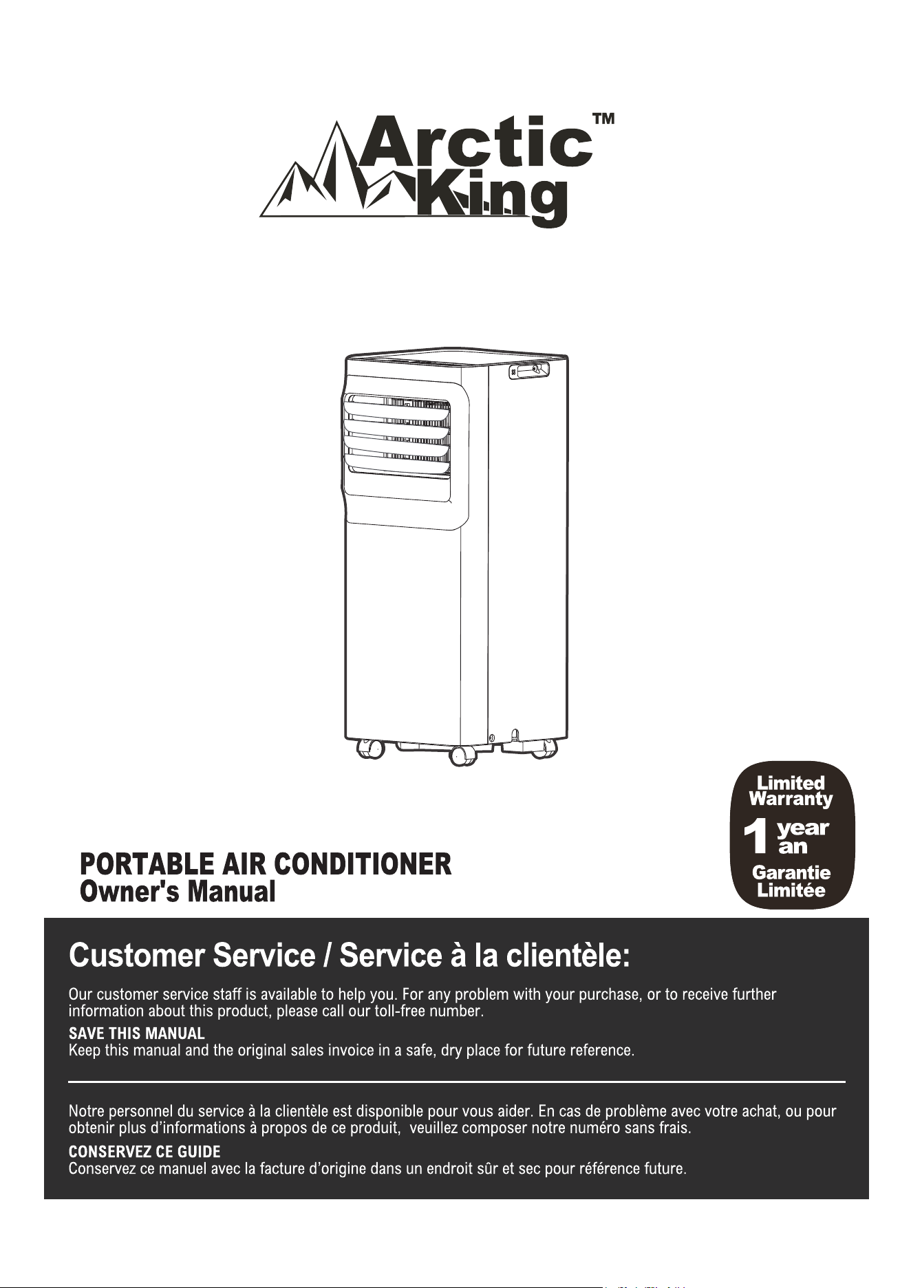
1-888-365-2230
SKu No. 21615112 Model NO. AAPA06R5RWT

TABLE OF CONTENTS
1
Safety Precautions.................................................................................................................................3
Installation Instructions ..........................................................................................................................11
Operating Instructions ...........................................................................................................................17
Drainage guide.....................................................................................................................................19
Cleaning & maintenance .....................................................................................................................20
Store the unit when not in use ............................................................................................................21
Troubleshooting ..................................................................................................................................22
Air Conditioner Limited Warranty...........................................................................................................35
Remote Controller Illustration ................................................................................................................23
Safety
Page 3
Safety
Precautions
Safety Precautions
Page 3
Read Safety Precautions Before Operation and Installation
To prevent death or injury to the user or other people and property damage, the
following instructions must be followed. Incorrect operation due to ignoring of
instructions may cause death, harm or damage.
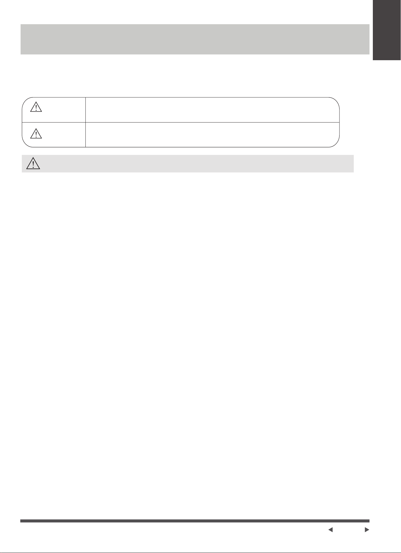
WARNING
• Installation must be performed according to the installation instructions.
Improper installation can cause water leakage, electrical shock, or fire.
• Use only the included accessories and parts, and specified tools for the
installation. Using nonstandard parts can cause water leakage, electrical shock,
fire, and injury or property damage.
• Make sure that the outlet you are using is grounded and has the appropriate
voltage.
The power cord is equipped with a three-prong grounding plug to protect
against shock.
Voltage information can be found on the nameplate of the unit.
• Your unit must be used in a properly grounded wall receptacle. If the wall
receptacle you intend to use is not adequately grounded or protected by a
time delay fuse or circuit breaker (the fuse or circuit breaker needed is
determined by the maximum current of the unit. The maximum current is
indicated on the nameplate located on unit), have a qualified electrician install
the proper receptacle.
• Install the unit on a flat, sturdy surface. Failure to do so could result in
damage or excessive noise and vibration.
• The unit must be kept free from obstruction to ensure proper function and to
mitigate safety hazards.
• Do not modify the length of the power cord or use an extension cord to
power the unit.
• Do not share a single outlet with other electrical appliances. Improper power
supply can cause fire or electrical shock.
• Do not install your air conditioner in a wet room such as a bathroom or
laundry room. Too much exposure to water can cause electrical components
to short circuit.
• Do not install the unit in a location that may be exposed to combustible gas,
as this could cause fire.
• The unit has wheels to facilitate moving. Make sure not to use the wheels on
thick carpet or to roll over objects, as these could cause tipping.
• Do not operate a unit that it has been dropped or damaged.
• The appliance with electric heater shall have at least 1 meter space to the
combustible materials.
• Do not touch the unit with wet or damp hands or when barefoot.
WARNING
CAUTION
This symbol indicates the possibility of personnel injury or
loss of life.
This symbol indicates the possibility of property damage
or serious consequences.
Safety
Precautions
Page 4
• In a thunderstorm, the power must be cut off to avoid damage to the
machine due to lightning.
• Your air conditioner should be used in such a way that it is protected from
moisture. e.g. condensation, splashed water, etc. Do not place or store your
air conditioner where it can fall or be pulled into water or any other liquid.
Unplug immediately if it occurs.
• All wiring must be performed strictly in accordance with the wiring diagram
located inside of the unit.
• The unit's circuit board(PCB) is designed with a fuse to provide overcurrent
protection. The specifications of the fuse are printed on the circuit board,
such as: T 3.15A/250V, etc.
• When the water drainage function is not in use, keep the upper and the lower
drain plug firmly to the unit to get rid of choking. When the drain plug is not
in use, keep it carefully to prevent children from choking.
• This appliance is not intended for use by persons (including childern) with
reduced physical, sensory or mental capabilities or lack of experience and
knowledge, unless they have been given supervision or instruction
concerning use of the appliance by a person responsible for their safety.
Children should be supervised to ensure that they do not play with the
appliance. Children must be supervised around the unit at all times.(be
applicable for other countries except the European Countries )
• If the supply cord is damaged, it must be replaced by the manufacturer,its
service agent or similarly qualified persons in order to avoid a hazard.
• Prior to cleaning or other maintenance, the appliance must be disconnected
from the supply mains.
• Do not remove any fixed covers. Never use this appliance if it is not working
properly, or if it has been dropped or damaged.
• Do not run cord under carpeting. Do not cover cord with throw rugs, runners,
or similar coverings. Do not route cord under furniture or appliances. Arrange
cord away from traffic area and where it will not be tripped over.
• Do not operate unit with a damaged cord, plug, power fuse or circuit breaker.
Discard unit or return to an authorized service facility for examination and/or
repair.
• To reduce the risk of fire or electric shock, do not use this fan with any
solid-state speed control device.
• The appliance shall be installed in accordance with national wiring regulations.
• Contact the authorised service technician for repair or maintenance of this unit.
• Contact the authorised installer for installation of this unit.
• Do not cover or obstruct the inlet or outlet grilles.
• Do not use this product for functions other than those described in this
instruction manual.
• Before cleaning, turn off the power and unplug the unit.
• Disconnect the power if strange sounds, smell, or smoke comes from it.
• Do not press the buttons on the control panel with anything other than your
fingers.
• Do not remove any fixed covers. Never use this appliance if it is not working
properly, or if it has been dropped or damaged.
• Do not operate or stop the unit by inserting or pulling out the power cord plug.
• If the air conditioner is knocked over during use, turn off the unit and unplug
it from the main power supply immediately. Visually inspect the unit to ensure
there is no damage. If you suspect the unit has been damaged, contact a
technician or customer service for assistance.
CAUTION
Safety
Precautions
Page 5
• Do not use hazardous chemicals to clean or come into contact with the unit.
Do not use the unit in the presence of inflammable substances or vapour
such as alcohol, insecticides, petrol,etc.
• Always transport your air conditioner in a vertical position and stand on a
stable, level surface during use.
• Always contact a qualified person to carry out repairs. If the damaged power
supply cord must be replaced with a new power supply cord obtained from
the product manufacturer and not repaired.
• Hold the plug by the head of the power plug when taking it out.
• Turn off the product when not in use.
CAUTION
Electronic Work
WARNING:
BEFORE PERFORMING ANY ELECTRICAL OR WIRING WORK, TURN OFF THE
MAIN POWER TO THE SYSTEM.
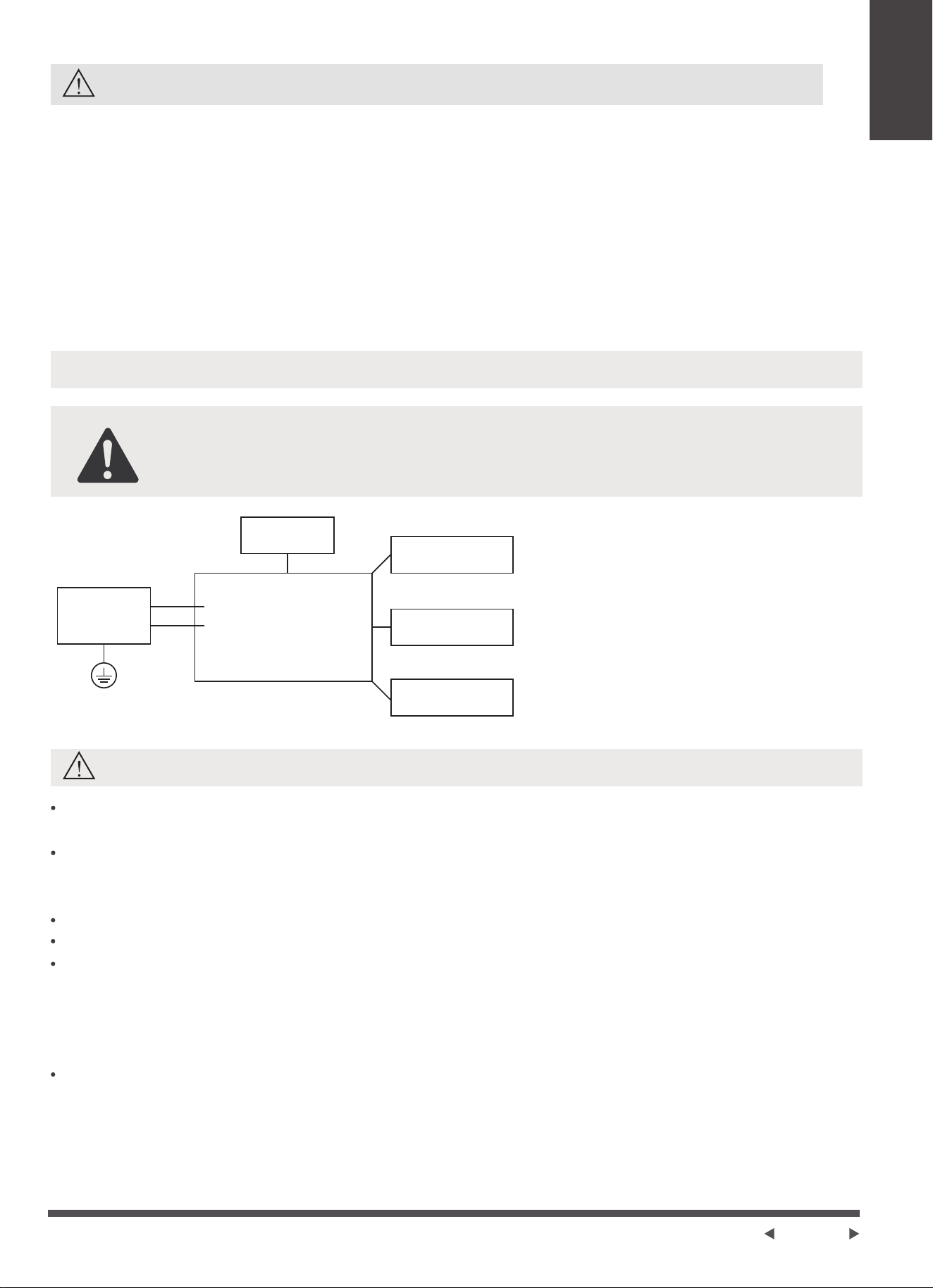
NOTICE: Please strictly follow the
wiring label attached to the machine
for all wiring connections. The wiring
diagram may vary for different unit.
Please refer to the wiring diagram on
the machine you have purchased.
The above wiring diagram is a
simplified version for preliminary
illustration purposes only.
Main Control
Compressor
Fan Motor
Display
Power
Supply
L/AC L/L1/L-IN
N/AC N/L2/N-IN
Other
WARNING for Using R32 Refrigerant
Do not use means to accelerate the defrosting process or to clean, other than those
recommended by the manufacturer.
The appliance shall be stored in a room without continuously operating ignition
sources (for example: open flames, an operating gas appliance or an operating
electric heater).
Do not pierce or burn.
Be aware that the refrigerants may not contain an odour.
Appliance should be installed, operated and stored in a room with a floor area
according to the amount of refrigerant to be charged. For specific information on
the type of gas and the amount, please refer to the relevant label on the unit itself.
When there are differences between the lable and the manual on the Min. room area
description, the description on label shall prevail.
Appliance shall be installed, operated and stored in a room with a floor area larger
than 4 m
2
.
Appliance shall not be installed in an unvertilated space, if that space is smaller
than 4 m
2
.
Safety
Precautions
Page 6
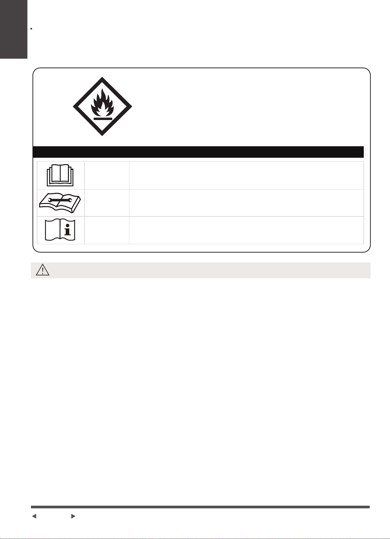
CAUTION:
Risk of fire
flammable materials
Explanation of symbols displayed on the unit
CAUTION
CAUTION
CAUTION
This symbol shows that the operation manual should be
read carefully.
This symbol shows that a service personnel should be
handling this equipment with reference to the installation
manual.
This symbol shows that information is available such as
the operating manual or installation manual.
No any open fire or device like switch which may generate spark/arcing shall be
around appliance to avoid causing ignition of the flammable refrigerant used.
Please follow the instructions carefully when storing or maintaining the appliance
to prevent mechanical damage from occurring.
WARNING
-Servicing shall only be performed as recommended by the equipment manufacturer.
Maintenance and repair requiring the assistance of other skilled personnel shall be
carried out under the supervision of the person competent in the use of flammable
refrigerants.
-DO NOT modify the length of the power cord or use an extension cord to power the
unit.
-DO NOT share a single outlet with other electrical appliances. Improper power supply
can cause fire or electrical shock.
-Please follow the instruction carefully to handle, install, clear, service the appliance to
avoid any damage or hazard.
-When maintaining or disposing the appliance, the refrigerant shall be recovered
properly, shall not discharge to air directly.
-Compliance with national gas regulations shall be observed.
-Keep ventilation openings clear of obstruction.
-The appliance shall be stored so as to prevent mechanical damage from occurring.
-A warning that the appliance shall be stored in a well-ventilated area where the room
size corresponds to the room area as specified for operation.
-Any person who is involved with working on or breaking into a refrigerant circuit
should hold a current valid certificate from an industry-accredited assessment
authority, which authorises their competence to handle refrigerants safely in
accordance with an industry recognised assessment specification. All training shall
follow the ANNEX HH requirements of UL 60335-2-40 4th Edition.
A2L

Safety
Precautions
Page 7
breaking into the refrigerating circuit;
Examples for such working procedures are:
opening of sealed components;
opening of ventilated enclosures.
See transport regulations.
1.Transport of equipment containing flammable refrigerants
See local regulations.
2.Marking of equipment using signs
See national regulations.
3.Disposal of equipment using flammable refrigerants
The storage of the appliance should be in accordance with the applicable
regulations or instructions, whichever is more stringent.
4.Storage of equipment/appliances
Storage package protection should be constructed such that mechanical damage to
the equipment inside the package will not cause a leak of the refrigerant charge.
The maximum number of pieces of equipment permitted to be stored together will
be determined by local regulations.
5.Storage of packed (unsold) equipment
1)Checks to the area
Prior to beginning work on systems containing flammable refrigerants, safety
checks are necessary to ensure that the risk of ignition is minimised. For repair to
the refrigerating system, the following precautions shall be complied with prior to
conducting work on the system.
6.Information on servicing
2)Work procedure
Work shall be undertaken under a controlled procedure so as to minimise the
risk of a flammable gas or vapour being present while the work is being
performed.
3)General work area
All maintenance staff and others working in the local area shall be instructed on the
nature of work being carried out. Work in confined spaces shall be avoided. The
area around the workspace shall be sectioned off. Ensure that the conditions within
the area have been made safe by control of flammable material.
4)Checking for presence of refrigerant
The area shall be checked with an appropriate refrigerating detector prior to and
during work, to ensure the technician is aware of potentially flammable atmospheres.
Ensure that the leak detection equipment being used is suitable for use with
flammable refrigerants, i.e. non-sparking, adequately sealed or intrinsically safe.
5)Presence of fire extinguisher
If any hot work is to be conducted on the refrigeration equipment or any associated
parts, appropriate fire extinguishing equipment shall be available to hand. Have a
dry powder or CO2 fire extinguisher adjacent to the charging area.
6)No ignition sources
No person carrying out work in relation to a refrigerating system which involves
exposing any pipe work that contains or has contained flammable refrigerant shall
use any sources of ignition in such a manner that it may lead to the risk of fire or
explosion. All possible ignition sources, including cigarette smoking, should be kept
sufficiently far away from the site of installation, repairing, removing and disposal,
during which flammable refrigerant can possibly be released to the surrounding
space.

Safety
Precautions
Page 8
Prior to work taking place, the area around the equipment is to be surveyed
to make sure that there are no flammable hazards or ignition risks. No Smoking
signs shall be displayed.
7)Ventilated area
Ensure that the area is in the open or that it is adequately ventilated before breaking
into the system or conducting any hot work. A degree of ventilation shall continue
during the period that the work is carried out. The ventilation should safely disperse
any released refrigerant and preferably expel it externally into the atmosphere.
8)Checks to the refrigerating equipment
Where electrical components are being changed, they shall be fit for the purpose
and to the correct specifications. At all times the manufacturer's maintenance and
service guidelines shall be followed. If in doubt consult the manufacturer's technical
department for assistance. The following checks shall be applied to installations
using flammable refrigerants: the actual refrigerant charge is in accordance with the
room size within which the refrigerant containing parts are installed; the ventilation
machinery and outlets are operating adequately and are not obstructed; if an
indirect refrigerating circuit is being used, the secondary circuit shall be checked
for the presence of refrigerant; marking to the equipment continues to be visible
and legible.
Markings and signs that are illegible shall be corrected; and refrigerating pipe or
components are installed in a position where they are unlikely to be exposed to
any substance which may corrode refrigerant containing components, unless the
components are constructed of materials which are inherently resistant to being
corroded or are suitably protected against being so corroded.
9)Checks to electrical devices
Repair and maintenance to electrical components shall include initial safety
checks and component inspection procedures. If a fault exists that could
compromise safety, then no electrical supply shall be connected to the circuit until
it is satisfactorily dealt with. If the fault cannot be corrected immediately but it is
necessary to continue operation, an adequate temporary solution shall be used.
This shall be reported to the owner of the equipment so all parties are advised.
Initial safety checks shall include: That capacitors are discharged: this shall be
done in a safe manner to avoid possibility of sparking; that there no live electrical
components and wiring are exposed while charging, recovering or purging the
system; that there is continuity of earth bonding.
Check that cabling will not be subject to wear, corrosion, excessive pressure,
vibration, sharp edges or any other adverse environmental effects. The check shall
also take into account the effects of aging or continual vibration from sources such
as compressors or fans.
9.Cabling
7.Sealed electrical components shall be replaced
8.Intrinsically safe components must be replaced
Under no circumstances shall potential sources of ignition be used in the searching
for or detection of refrigerant leaks. A halide torch (or any other detector using a
naked flame) shall not be used. The following leak detection methods are deemed
acceptable for systems containing flammable refrigerants. Electronic leak detectors
shall be used to detect flammable refrigerants, but the sensitivity may not be
adequate, or may need re-calibration. (Detection equipment shall be calibrated in a
refrigerant-free area.)
10.Detection of flammable refrigerants

Safety
Precautions
Page 9
In addition to conventional charging procedures, the following requirements shall
be followed. Ensure that contamination of different refrigerants does not occur
when using charging equipment. Hoses or lines shall be as short as possible to
minimise the amount of refrigerant contained in them. Cylinders shall be kept in
an appropriate position according to the instructions. Ensure that the refrigeration
system is earthed prior to charging the system with refrigerant. Label the system
when charging is complete (if not already). Extreme care shall be taken not to
overfill the refrigeration system. Prior to recharging the system it shall be pressure
tested with OFN. The system shall be leak tested on completion of charging but
prior to commissioning. A follow up leak test shall be carried out prior to leaving
the site.
12.Charging procedures
Ensure that the detector is not a potential source of ignition and is suitable for the
refrigerant used. Leak detection equipment shall be set at a percentage of the LFL
of the refrigerant and shall be calibrated to the refrigerant employed and the
appropriate percentage of gas (25 % maximum) is confirmed.
Leak detection fluids are suitable for use with most refrigerants but the use of
detergents containing chlorine shall be avoided as the chlorine may react with the
refrigerant and corrode the copper pipe-work. If a leak is suspected, all naked
flames shall be removed/ extinguished. If a leakage of refrigerant is found which
requires brazing, all of the refrigerant shall be recovered from the system, or
isolated (by means of shut off valves) in a part of the system remote from the leak.
Removal of refrigerant shall be according to Removal and evacuation.
When breaking into the refrigerant circuit to make repairs—or for any other
purpose - conventional procedures shall be used. However, for flammable
refrigerants it is important that best practice be followed, since flammability is a
consideration. The following procedure shall be adhered to:
-Safely remove refrigerant following local and national regulations;
-Evacuate;
-Purge the circuit with inert gas (optional for A2L);
-Evacuate (optional for A2L);
-continuously flush or purge with inert gas when using flame to open circuit; and
-open the circuit.
The refrigerant charge shall be recovered into the correct recovery cylinders if
venting is not allowed by local and national codes. For appliances containing
flammable refrigerants, the system shall be purged with oxygen-free nitrogen
flammable refrigerants. This process might compressed air or oxygen shall not
be used for purging refrigerant systems.
For appliances containing flammable refrigerants, refrigerants purging shall be
achieved by breaking the vacuum in the system with oxygen-free nitrogen and
continuing to fill until the working pressure is achieved, then venting to atmosphere,
and finally pulling down to a vacuum (optional for A2L).
This process shall be repeated until no refrigerant is within the system (optional for
A2L). When the final oxygen-free nitrogen charge is used. the system shall be
vented down to atmospheric pressure to enable work to take place. The outlet for
the vacuum pump shall not be close to any potential ignition sources, and
ventilation shall be available.
11.Removal and evacuation

Safety
Precautions
Page 10
Before carrying out this procedure, it is essential that the technician is completely
familiar with the equipment and all its detail. It is recommended good practice
that all refrigerants are recovered safely. Prior to the task being carried out, an oil
and refrigerant sample shall be taken in case analysis is required prior to re-use
of reclaimed refrigerant. It is essential that electrical power is available before the
task is commenced.
a) Become familiar with the equipment and its operation.
b) Isolate system electrically.
c) Before attempting the procedure ensure that: Mechanical handling equipment
is available, if required, for handling refrigerant cylinders;all personal protective
equipment is available and being used correctly; the recovery process is
supervised at all times by a competent person; recovery equipment and
cylinders conform to the appropriate standards.
d) Pump down refrigerant system, if possible.
e) If a vacuum is not possible, make a manifold so that refrigerant can be removed
from various parts of the system.
f) Make sure that cylinder is situated on the scales before recovery takes place.
g) Start the recovery machine and operate in accordance with manufacturer's
instructions.
h) Do not overfill cylinders. (No more than 80 % volume liquid charge).
i) Do not exceed the maximum working pressure of the cylinder, even temporarily.
j) When the cylinders have been filled correctly and the process completed, make
sure that the cylinders and the equipment are removed from site promptly and
all isolation valves on the equipment are closed off.
k) Recovered refrigerant shall not be charged into another refrigeration system
unless it has been cleaned and checked.
13.Decommissioning
Equipment shall be labelled stating that it has been de-commissioned and emptied
of refrigerant. The label shall be dated and signed. Ensure that there are labels on
the equipment stating the equipment contains flammable refrigerant.
14.Labelling
When removing refrigerant from a system, either for servicing or decommissioning,
it is recommended good practice that all refrigerants are removed safely. When
transferring refrigerant into cylinders, ensure that only appropriate refrigerant
recovery cylinders are employed. Ensure that the correct number of cylinders for
holding the total system charge is available. All cylinders to be used are designated
for the recovered refrigerant and labelled for that refrigerant (i.e. special cylinders
for the recovery of refrigerant). Cylinders shall be complete with pressure relief
valve and associated shut-off valves in good working order. Empty recovery
cylinders are evacuated and, if possible, cooled before recovery occurs. The recovery
equipment shall be in good working order with a set of instructions concerning the
equipment that is at hand and shall be suitable for the recovery of the flammable
refrigerant. If in doubt, the manufacturer should be consulted. In addition, a set of
calibrated weighing scales shall be available and in good working order. Hoses
shall be complete with leak-free disconnect couplings and in good condition.
The recovered refrigerant shall be processed according to local legislation in the
correct recovery cylinder, and the relevant waste transfer note arranged. Do not
mix refrigerants in recovery units and especially not in cylinders. If compressors or
compressor oils are to be removed, ensure that they have been evacuated to an
acceptable level to make certain that flammable refrigerant does not remain within
the lubricant. The compressor body shall not be heated by an open flame or other
ignition sources to accelerate this process. When oil is drained from a system, it
shall be carried out safely.
15.Recovery
Page 11
Installation
Instructions
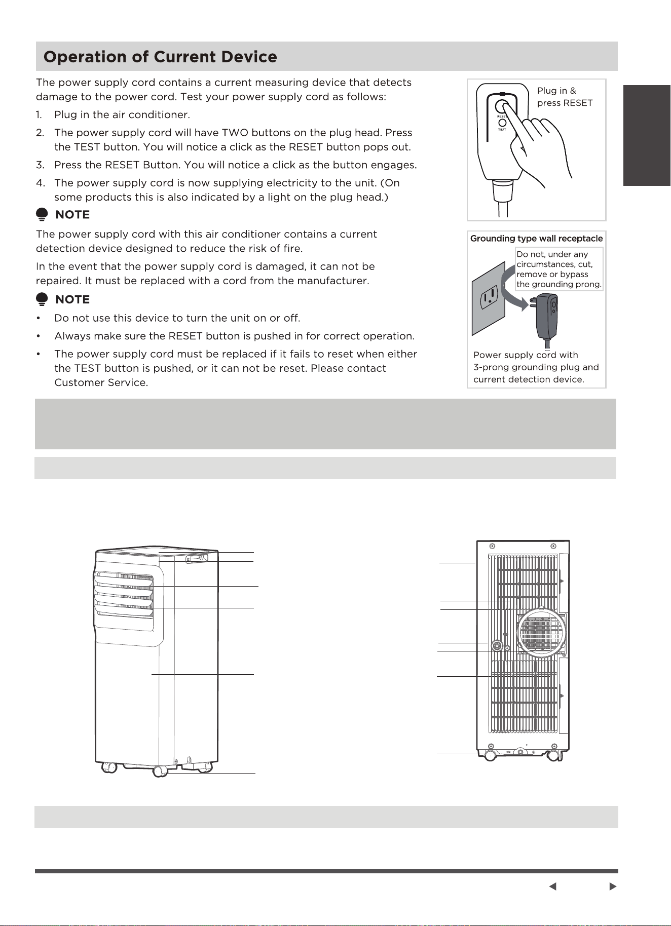
Installation Instructions
Preparation
NOTE:
All the illustrations in the manual are for explanation purpose only. Your machine may be slightly different.
The actual shape shall prevail. The unit can be controlled by the unit control panel alone or with the remote
controller.
Design Notice
In order to ensure the optimal performance of our products, the design specifications of the
unit and remote control are subject to change without prior notice.
Rear View
Handle
(both sides)
Air filter
upper air intake
Air outlet
Lower air intake
Drain outlet
Bottom tray
drain outlet
louver control
Curved air outlet
lever-manual adjustment
(On some models)
Control panel
Remote signal receptor
Front panel
Caster
Front View
Page 12
Installation
Instructions
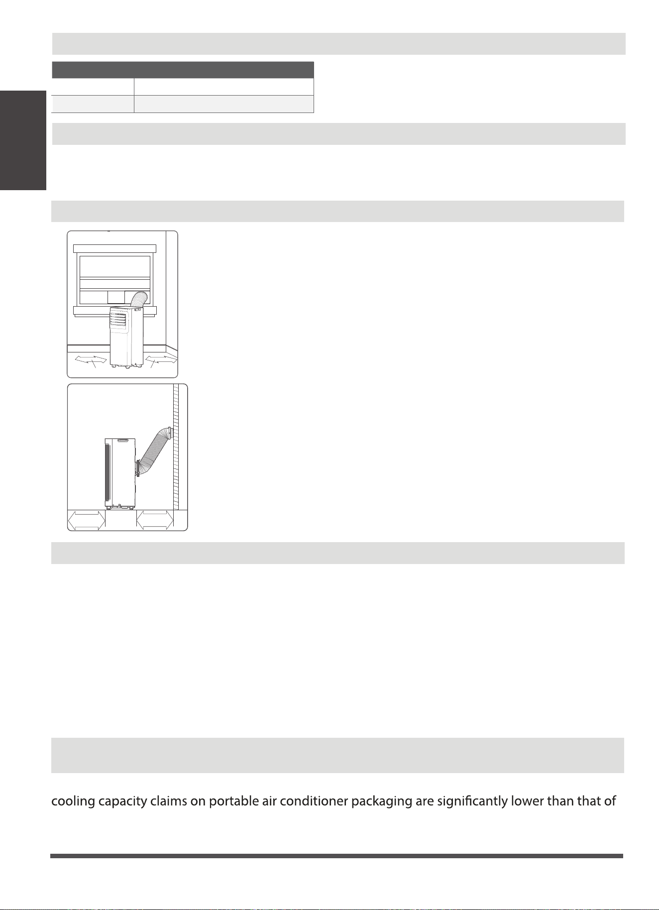
Choosing The Right Location
Your installation location should meet the following requirements:
-Make sure that you install your unit on an even surface to minimize noise and
vibration.
-The unit must be installed near a grounded plug, and the Collection Tray Drain
(found on the back of the unit) must be accessible.
-The unit should be located at least 30cm (12”) from the nearest wall to ensure
proper air conditioning. The horizontal louver blade should be at least 50cm
(19.7”) away from obstacles.
-DO NOT cover the Intakes, Outlets or Remote Signal Receptor of the unit, as this
could cause damage to the unit.
Energy Rating Information
How to Stay Cool with a New Portable Air Conditioner(For the models comply with the
requirements of Department Of Energy in US)
Because of a new federal test procedure for Portable Air Conditioners, you may notice that the
models produced prior to 2017. This is due to changes in the test procedure, not to the portable
air conditioners themselves.
The unit with 3 meters extended exhaust duct is running by using 2 exhaust ducts(Diameter:150mm, Length:1.5m
+ Diameter: 130mm, Length: 1.5m) .The Energy rating and noise information for unit with 3 meters extended
exhaust duct is not assessed.(For some models)
NOTE:
We recommend that operating the unit at room temperature below 35
°C
. Since there is a risk that the unit with 3
meters extended exhaust duct would not work at room temperature above 35
°C
under some extreme conditions,
such as the lower air intake be blocked for 50%.
The energy rating and noise information for this unit is based on the standard installation using an un-extended
exhaust duct without window slider adaptor (as shown in the Installation section of this manual). At the
same time, the unit must be operated on the COOL MODE and HIGH FAN SPEED by remote controller.
Ambient Temperature Range For Unit Operating
Exhaust Hose Installation
The exhaust hose and adaptor must be installed or removed in accordance with the usage mode. For
COOL,HEAT(heat pump type) or AUTO mode must be installed exhaust hose. For FAN, DRY or HEAT
(electrical heat type) mode must be removed exhaust hose.
MODE Temperature Range
Cool 16-35°C (60-95°F)
Dry 13-35°C (55-95°F)
≥30cm(12’’)
≥50cm
19.7’’
≥50cm
19.7’’
≥30cm(12’’)
Page 13
Installation
Instructions
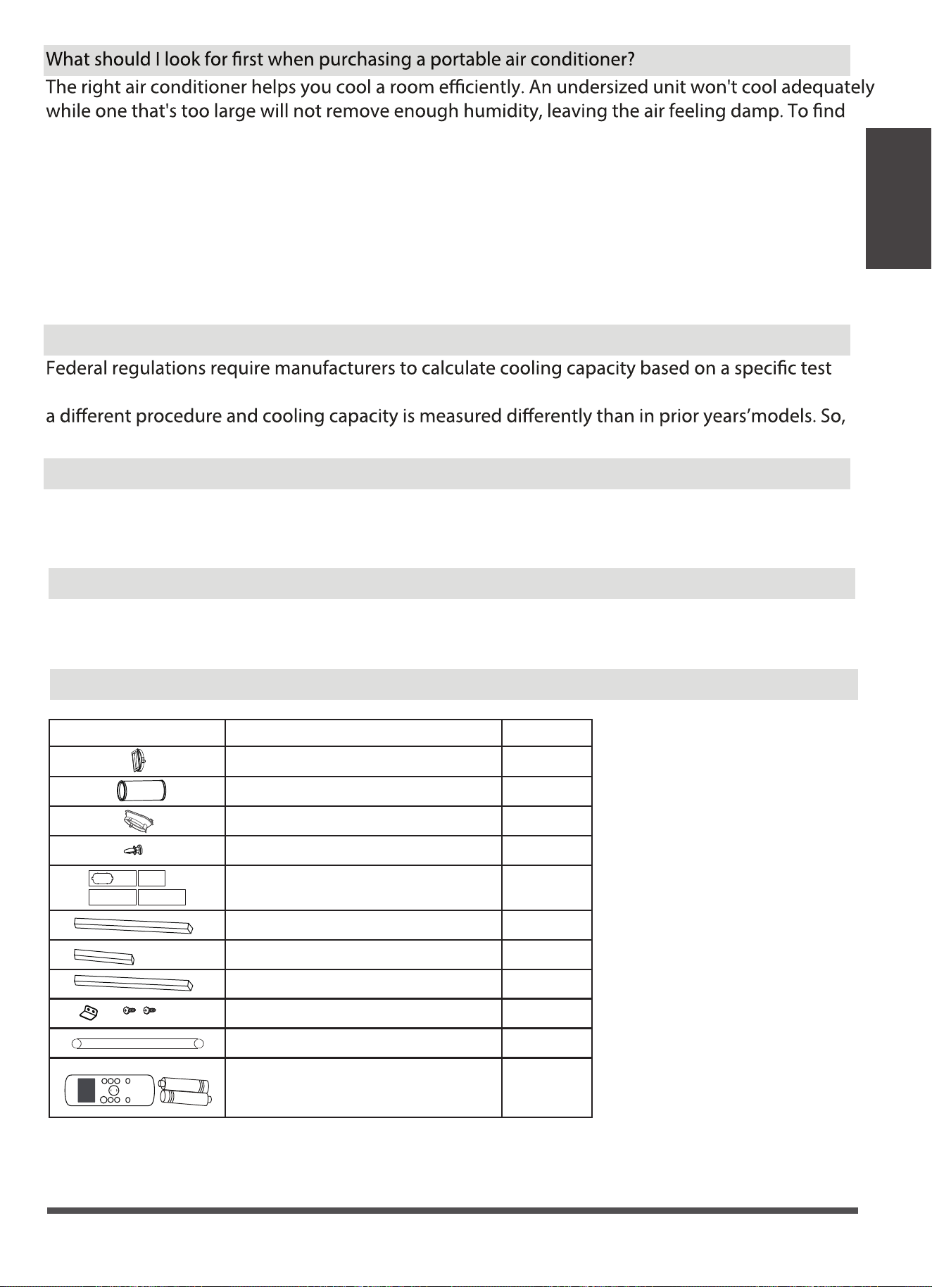
Accessories
Tools Needed
-Medium Philips screwdriver; -Tape measure or ruler; -Knife or scissors;
-Saw (optional, to shorten window adaptor for narrow windows)
the proper air conditioner, determine the square footage of the room you want to cool by
multiplying the room length by its width. You also need to know the air conditioner's BTU (British
Thermal Unit) rating, which indicates the amount of heat it can remove from a room. A higher
Why is the cooling capacity lower on newer models than on older units?
number means more cooling power for a larger room. (Be sure you are comparing only newer
models to each other- older models may appear to have a higher capacity, but are actually the
same). Be sure to “size up” if your portable air conditioner will be placed in a very sunny room, in a
kitchen, or in a room with high ceilings. After you’ve found the right cooling capacity or your
room, you can look at other features.
procedure, which was changed just this year. Models manufactured before 2017 were tested under
while the BTUs may be lower, the actual cooling capacity of the air conditioners has not changed.
What is SACC ?
SACC is the representative value of Seasonally Adjusted Cooling Capacity, in Btu/h, as determined
in accordance with the DOE test procedure at title 10 Code of Federal Regulations (CFR) 430,
subpart B, appendix CC and applicable sampling plans.
Shape
Description
1 pc
1 pc
1 pc
3 pc
2 pc
4 pc
2 pc
1 set
1 set
Unit Adaptor
Window Slider
Exhaust Hose
Bolt
Foam Seal A (Adhesive)
Foam Seal B (Adhesive)
Foam Seal C (Non-adhesive)
Security Bracket and 2 Screws
Drain Hose
Qty.
1 pc
O
N
/
O
F
F
T
E
M
P
S
H
O
R
T
C
U
T
T
I
M
E
R
O
N
T
I
M
E
R
O
F
F
M
O
DE
F
A
N
S
L
E
E
P
LE
D
Remote Controller and Battery
(only for remote control models)
Air exhaust passage
1 set
Page 14
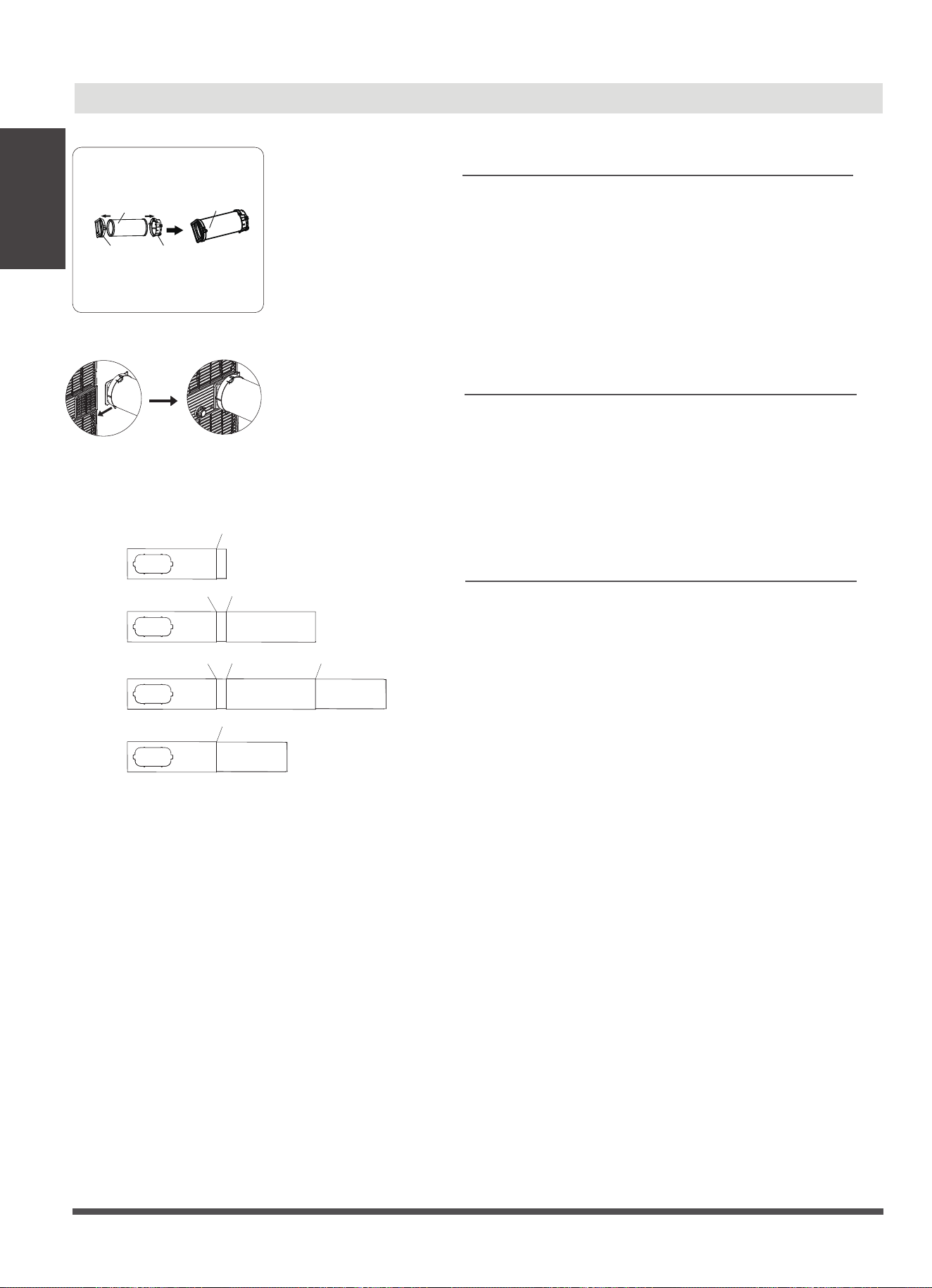
Window Installation Kit
Installation
Instructions
Press the exhaust hose(or extended exhaust hose)
into the window slider adaptor(or wall exhaust
adaptor) and unit adaptor, clamp automatically by
elastic buckles of the adaptors.
Step One: Preparing the Exhaust Hose assembly
Unit adaptor
Window slider
adaptor
Exhaust hose
Exhaust hose
assembly
Type window installation:
Model A
Step Three: Preparing the Adjustable Window
Slider
1. Choose the window sliders according the size of
your window. Sometimes, it needs to be cut short
to meet the window size, please take extra care to
cut it properly.
2. Use bolts to fasten the window sliders once they
are adjusted to the Proper length.
Step Two: Install the Exhaust hose assembly to
the unit
Push the Exhaust hose into the airoutlet opening of
the unit along the arrow direction.
1+2:
Bolt
1+2+3:
Bolt
Bolt
1+2+3+4:
Bolt
BoltBolt
1+4:
Bolt
Installation
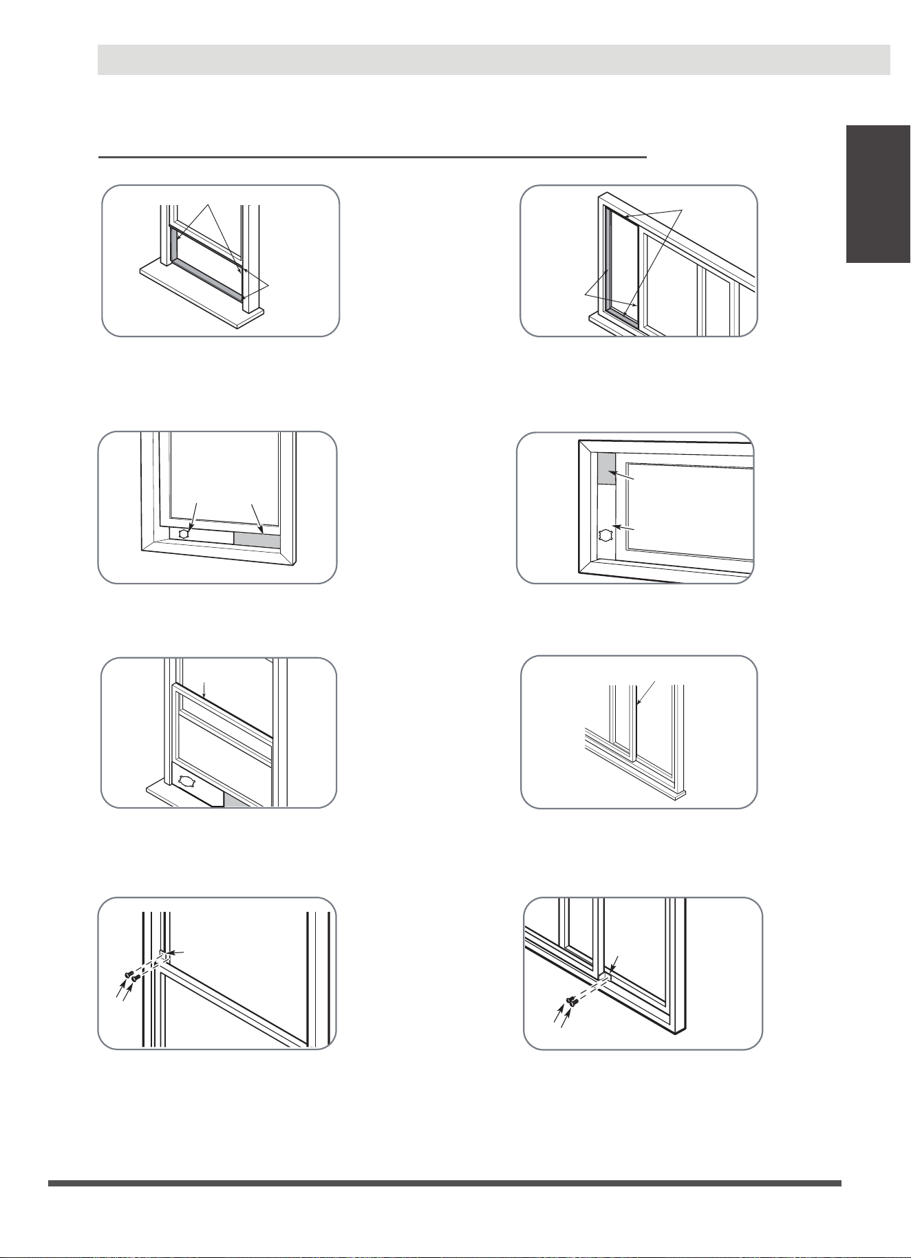
NOTE: Once the Exhaust Hose assembly and Adjustable Window Slider are prepared, choose from one of
the following two installation methods.
Or
Foam seal B
(Adhesive type-shorter)
Foam seal A
(Adhesive type)
Type 1: Hung Window or Sliding Window Installation(For some models)
1. Cut the adhesive foam seal A and B strips to the proper lengths, and attach them to the window sash
and frame as shown.
Foam seal B
(Adhesive type-shorter)
Foam seal A
(Adhesive type)
Or
Or
Window
slider A
Window slider
B(if required)
Foam seal C
(Non-adhesive type)
3. Cut the non-adhesive foam seal C strip to match the width(or height) of the window. Insert the seal
between the glass and the window frame to prevent air and insects from getting into the room.
2. Insert the window slider assembly into the window opening.
Window slider A
Window slider B
(if required)
Foam seal C
(Non-adhesive type)
Or
2 Screws
Security Bracket
4. If desired, install the security bracket with 2 screws as shown.
2 Screws
Security
Bracket
Page 15
Installation
Instructions
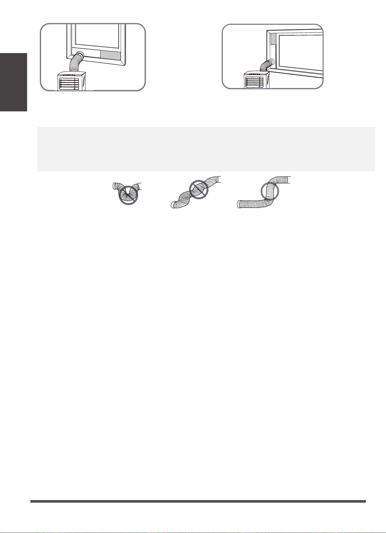
NOTE: To ensure proper function, DO NOT overextend or bend the hose. Make sure that there is no obstacle
around the air outlet of the exhaust hose (in the range of 500mm) in order to the exhaust system works
properly. All the illustrations in this manual are for explanation purpose only. Your air conditioner may be
slightly dierent. The actual shape shall prevail.
Or
5. Insert the window slider adaptor into the hole of the window slider.
Page 16
Installation
Instructions
Operating Instructions
Control Panel Features
NOTE: The following control panels
are for explanation purpose only. The control panel of the unit you
purchased may be slightly dierent according to the models. Your machine may not contain some indicators or
buttons. The actual shape shall prevail.
Operating
Instructions
Page 17
1. POWER button
2. MODE function
5. FAN function
6. COOL mode
Shows the set temperature while on Cool,
or Auto mode. It shows the room
temperature on DRY and FAN modes.
Shows Error codes:
EH00-EEPROM error.
EH60-Room temperature sensor error.
EH61-Evaporator temperature sensor error.
EC52-Condenser temperature sensor error
(on some models).
EH0b-Display panel communication error.
EC-Refrigerant leakage detection malfunction (on some
models).
Shows protection code:
P1-Bottom tray is full--Connect the drain hose and drain
the collected water away.
If protection repeats, call for service.
NOTE: When one of the above malfunctions occurs, turn
o the unit, and check for any obstructions. Restart the
unit, if the malfunction is still present, turn o the unit
and unplug the power cord. Contact the manufacturer,
its service agents or a similar qualied person for service.
Selects the appropriate operating mode.
Each time you press the button, the mode
is selected in a sequence that goes from
AUTO, DRY, COOL and FAN, The mode
indicator light illuminates under the
dierent mode setting.
Power switch on/o.
NOTE: In AUTO mode, the FAN speed will
be adjusted automatically.
3. UP and DOWN buttons
Used to adjust (increasing/decreasing)
temperature settings in 1°C/2°F (or 1°F)
increments in a range of 16°C/60°F to
30°C/88°F (or 86°F).
NOTE: The control is capable of displaying
temperature in degrees Fahrenheit or
degrees Celsius. To convert from one to
the other, press and hold the Up and
Down buttons at the same time for 3
seconds.
4. Display
Press to control the fan speed in four steps HIGH, LOW, Cont
and AUTO. The fan speed indicator light illuminates. under
dierent fan settings.
Press the "MODE" button until the "Cool" indicator light
comes on.
Press the ADJUST buttons "+" or "-" to select your the
COOL mode.
Press the "MODE" button until the "Dry" indicator light
comes on. In this mode, the fan speed or the temperature
cannot be adjusted. The fan motor operates at Auto speed.
NOTE:Keep windows and doors closed for the best
dehumidifying eect. Do not put the duct to window.
7. DRY mode
Press the "MODE" button until the "Auto" indicator light
comes on. In this mode, the fan speed or the temperature
will be adjusted automatically.
8. AUTO mode

Page 18
COMFORT SENSE feature (On some models)
To activate the Comfort Sense feature, point the remote control towards the unit and press the Comfort Sense
button. The remote control will send this signal to the AC until press the Comfort Sense button again. If the
unit does not receive the Comfort Sense signal during any 7 minutes interval, the unit will exit the Comfort
Sense mode.
NOTE: This feature is unavailabe under FAN or DRY mode.
9. Continuous Fan function
10. Other features
In COOL or DRY mode, press the Fan button for 3 seconds to turn on or o the continuous fan function. When
the function is turned on, the Cont. fan light will illuminate, indicating the fan will run continuously. When
the function is turned o, the Cont. fan light will go out, indicating that the fan will stop when the compressor
stops.
This feature can be activated from the remote control ONLY. There is no indicator light on the control panel.
The remote control serves as a remote thermostat allowing for the precise temperature control at its location.
Operating
Instructions
Remove the
bottom
drain plug
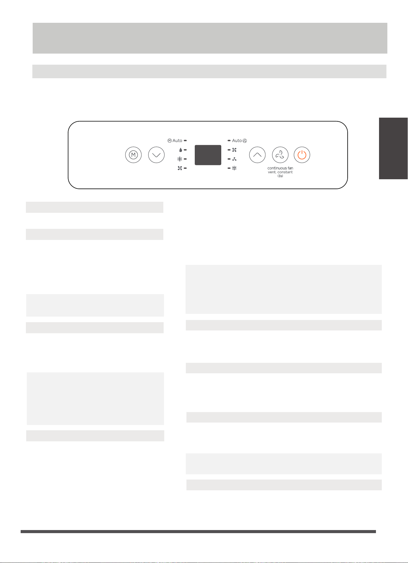
Water collection tray Drainage Guide
During dehumidifying modes, remove the drain plug from the
back of the unit, install the drain connector (5/8" universal
female mender) with 3/4" hose(locally purchased). For the
models without drain connector, just attach the drain hose to
the hole. Place the open end of the hose directly over the
drain area in your basement oor.
When the water level of the bottom tray reaches a predetermined
level, the unit beeps 8 times, the digital display area shows "P1" .
At this time the air conditioning/dehumidication process will
immediately stop.
However, the fan motor will continue to operate(this is normal).
Carefully move the unit to a drain location, remove the bottom
drain plug and let the water drain away. Reinstall the bottom
drain plug and restart the machine until the "P1" symbol
disappears. If the error repeats, call for service.
NOTE: Be sure to reinstall the bottom drain plug rmly to prevent
leakage before using the unit.
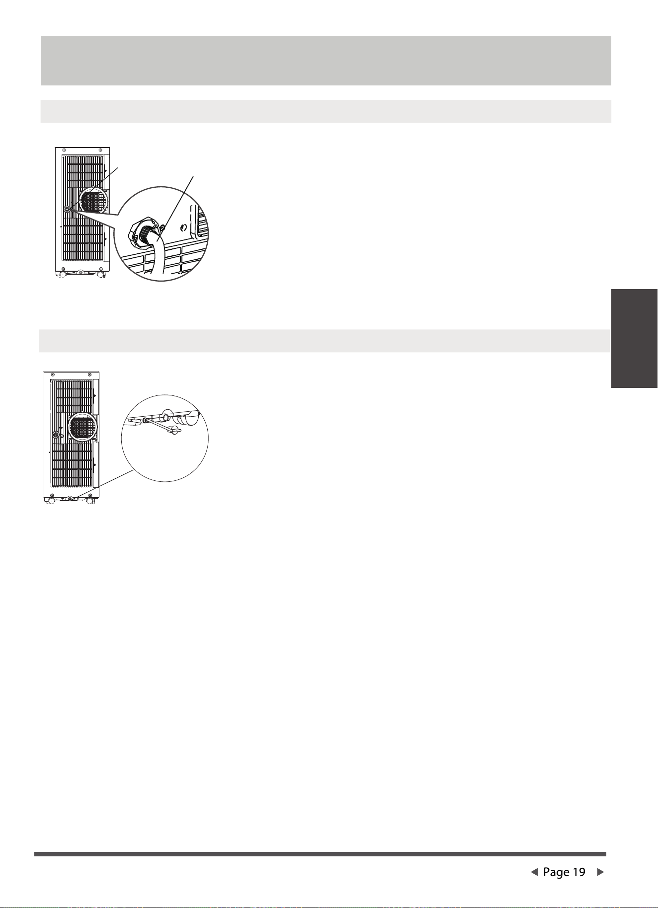
NOTE: Make sure the hose is secure so there are no leaks.
Direct the hose toward the drain,making sure that there are
no kinks that will stop the water owing. Place the end of
the hose into the drain and make sure the end of the hose is
down to let the water ow smoothly. When the continuous
drain hose is not used, ensure that the drain plug and knob
are installed rmly to prevent leakage.
Step 1:
Remove the
drain plug
Dehumidifying Mode Drainage Guide
Step 2:
Install the
continuous
drain hose
Drainage guide
Drainage guide
Page 20
Cleaning &
maintenance
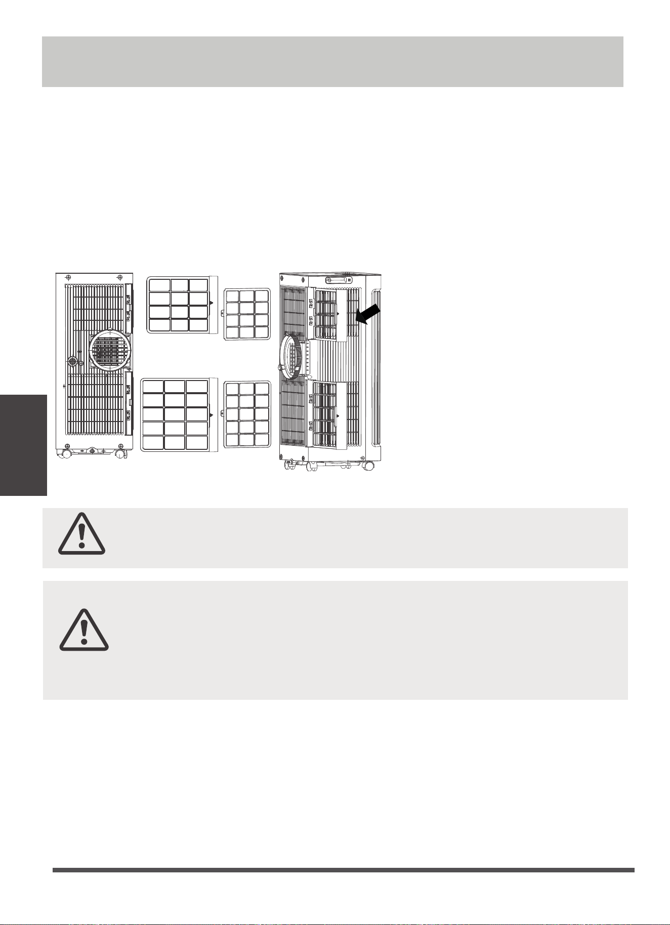
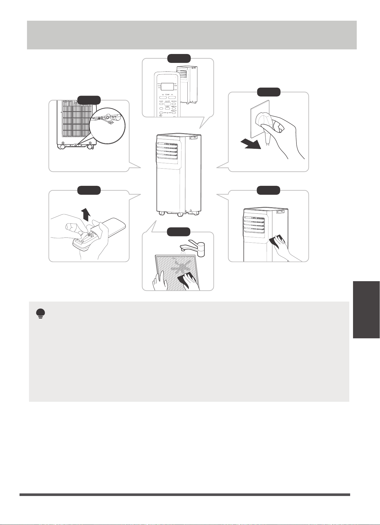
Air Filter & Cabinet Cleaning
Air lter
(take out)
Remove the air filter
CAUTION:
· Always unplug the unit before cleaning or servicing.
· DO NOT use ammable liquids or chemicals to clean the unit.
· DO NOT wash the unit under running water. Doing so causes electrical danger.
· DO NOT operate the machine if the power supply was damaged during cleaning.
A damaged power cord must be replaced with a new cord from the manufacturer.
CAUTION:
DO NOT operate the unit without lter because dirt and lint will clog it and reduce
performance.
Clean the unit using a damp, lint-free cloth and mild detergent. Dry the unit with a dry, lint-free cloth.
Maintenance Tips
· Be sure to clean the air lter every 2 weeks for optimal performance.
· The water collection tray should be drained immediately after P1 error occurs, and before storage to
prevent mold.
· In households with animals, you will have to periodically wipe down the grill to prevent blocked airow
due to animal hair.
Cleaning & maintenance
How to clean & maintenance your AC.
Store the unit
when not in use
NOTE
12hours
· Drain the unit’s water collection tray according to the instructions in the following section.
· Run the appliance on FAN mode for 12 hours in a warm room to dry it and prevent mold.
· Turn o the appliance and unplug it.
· Clean the air filter according to the instructions in the previous section. Reinstall the clean, dry filter
before storing.
· Remove the batteries from the remote control.
Be sure to store the unit in a cool, dark place. Exposure to direct sunshine or extreme heat
can shorten the lifespan of the unit.
The cabinet and front may be dusted with an oil-free cloth or washed with a cloth
dampened in a solution of warm water and mildliquid dishwashing detergent. Rinse
thoroughly and wipe dry.
Never use harsh cleansers, wax or polish on the cabinet front.
Be sure to wring excess water from the cloth before wiping around the controls.
Excess water in or around the controls may cause damage to the unit.
Step6
Step 3
Step4
Step 1
Step 2
Step 5
*Please refer to the actual
plug, and the legend is for
reference only.
*Drain the unit‘s water collection
tray then reinstall the bottom
drain plug back in.
·
·
SHORT CUT
C-SENSE
°C/°F
Store the unit when not in use
Page 21
Troubleshooting Tips
Problem Possible Causes Solution
Unit does not turn
on when pressing
ON/OFF button.
P1 Error Code.
In COOL mode: room
temperature is lower than
the set temperature.
Reset the temperature.
The Water Collection Tray is full. Turn off the
unit, drain the water from the Water Collection
Tray and restart the unit.
The air filter is blocked with
dust or animal hair.
The unit is low on
refrigerant.
Temperature setting is too
high.
The windows and doors in
the room are open.
The room area is too large.
Unit does not cool
well.
Exhaust hose is not
connected or is blocked.
There are heat sources
inside the room.
Turn off the unit and clean the filter according
to instructions.
Call a service technician to inspect
the unit and top off refrigerant.
Decrease the set temperature.
Make sure all windows and doors are closed.
Double-check the cooling area.
Turn off the unit, disconnect the hose, check for
blockage and reconnect the hose.
Remove the heat sources if possible.
The unit is noisy
and vibrates too
much.
The unit makes a
gurgling sound.
The ground is not level. Place the unit on a flat, level
surface.
The air filter is blocked with
dust or animal hair.
Turn off the unit and clean the filter according
to instructions.
This sound is caused by the
flow of refrigerant inside
the unit.
This is normal.
Page 22
Troubleshooting
Tips
Model
Rated voltage
8 m
3.0 V (dry batteries R03/LR03×2)
Environment
Signal receiving range
RG57H3(B2)/BGCEF-M
Remote Control Specifications
CAUTION:
INGESTION HAZARD - Contains small batteries, Keep out of reach of small
children. If swallowed, seek immediate medical attention.
O O O O
-5 C~60 C (23 F~140 F)
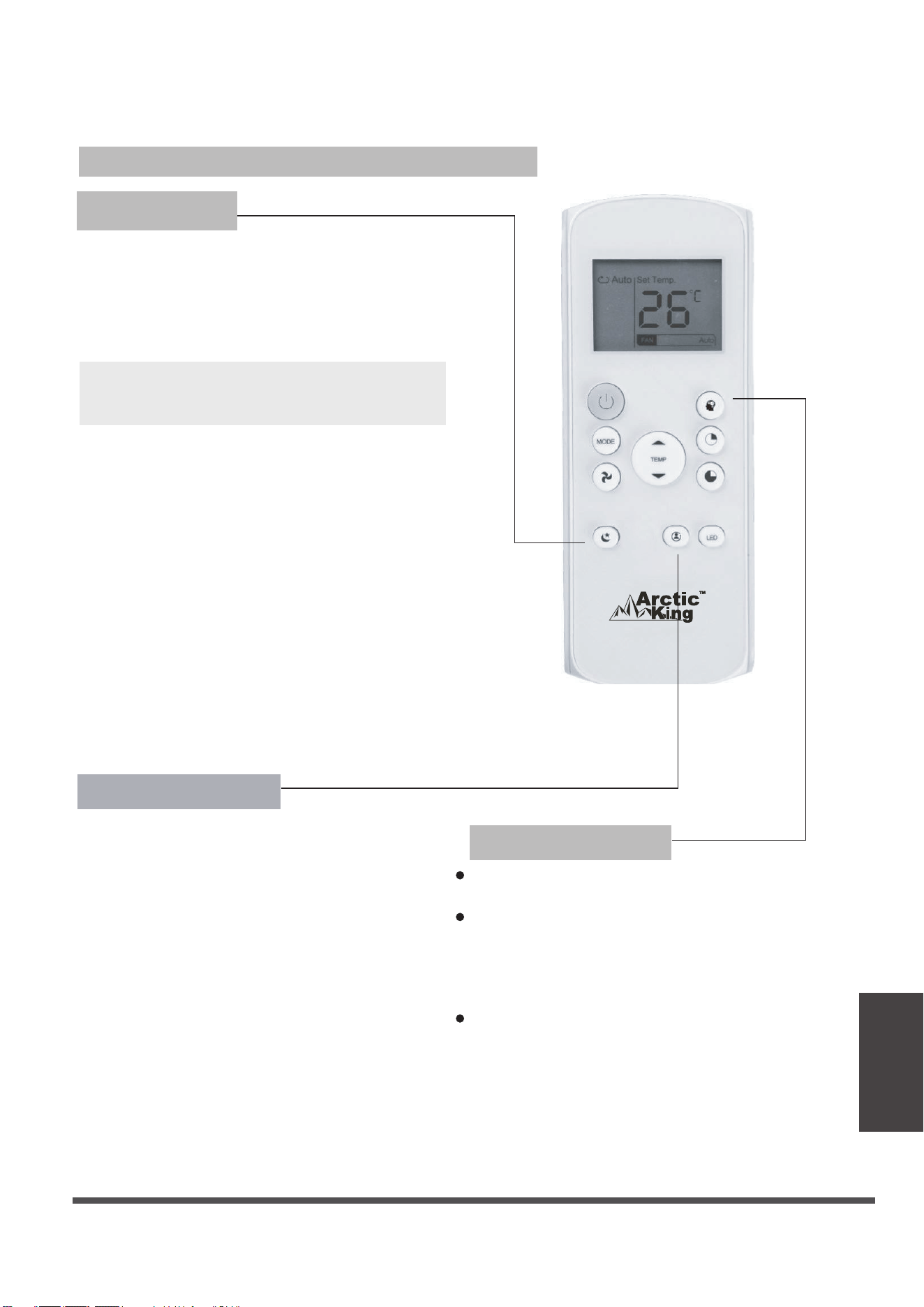
Remote Controller Illustration
Remote Controller
Illustration
Page 23
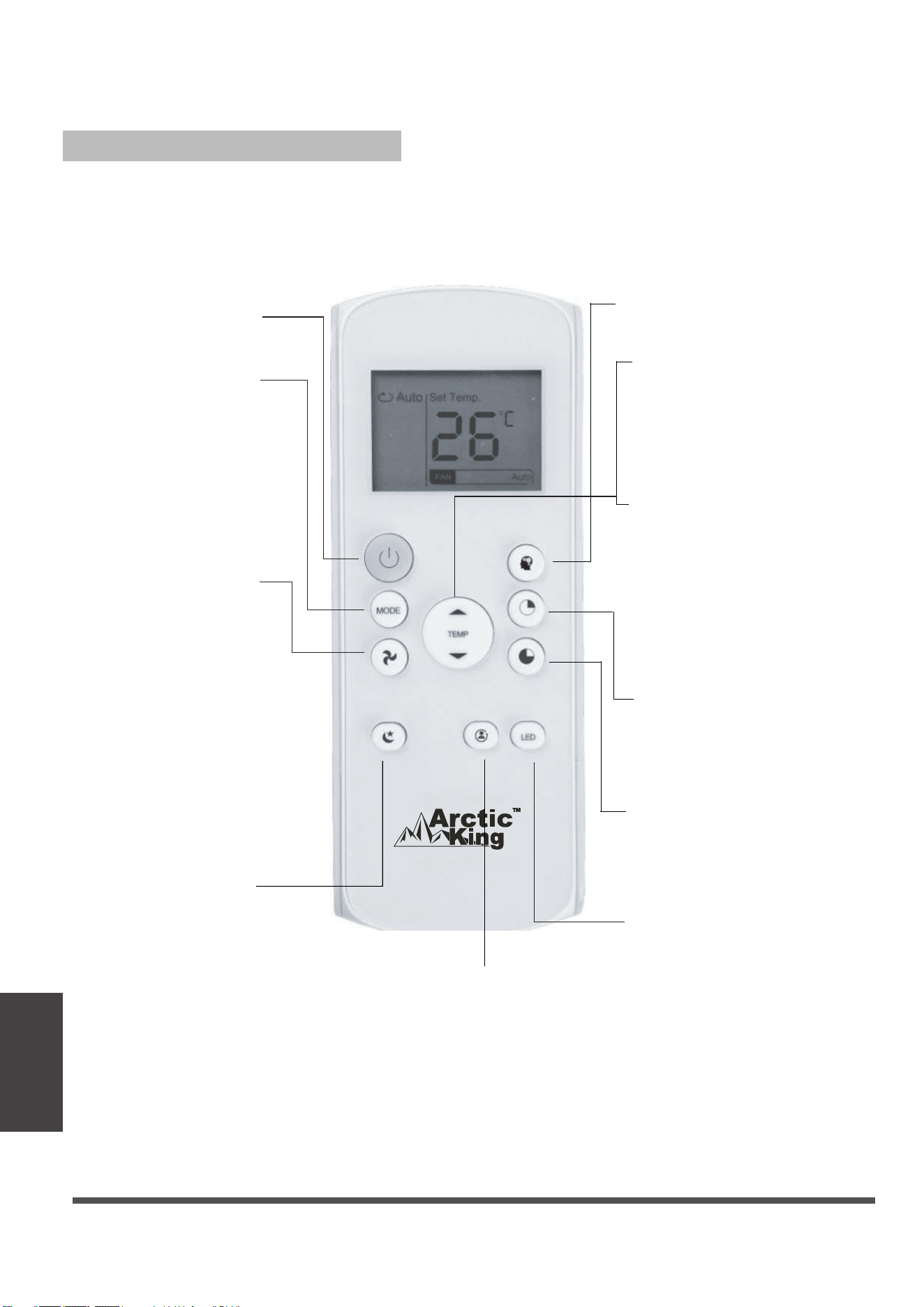
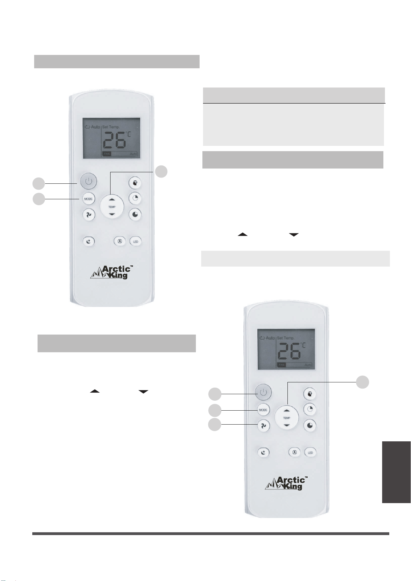
Function Buttons
Before using your new air conditioner, make sure to familiarize yourself with the remote
controller. The following is a brief introduction to the remote controller. For instructions on how to
operate your air conditioner, refer to the "How to Use the Basic Functions" section of this manual.
SHORT CUT
Sets and activates your
favourite presettings.
ON/OFF
Turns the unit on or off.
MODE
Scrolls through operation
modes as follows:
AUTO COOL DRY
FAN
FAN SPEED
Selects fan speeds in
the following order:
AUTO LOW
HIGH
SLEEP
Saves energy during
sleeping hours.
TEMP
Increases the temperature in
O O
1 C (1 F) increments.
Max. temperature is
O O
30 C (86 F) .
TEMP
Decreases temperature in
O O
1 C (1 F) increments.
Min. temperature is
O O
17 C (62 F).
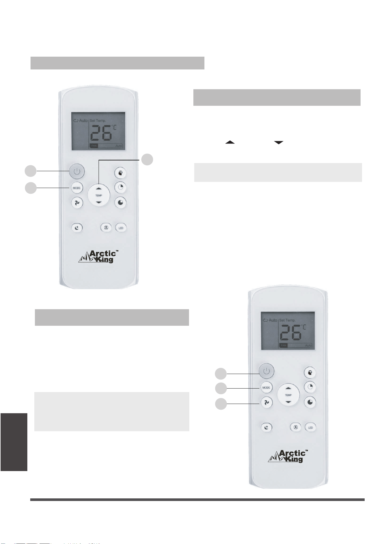
TIMER ON
Sets the timer to turn the unit
on (refer to " How to Use
Basic Functions " for
instructions).
TIMER OFF
Sets the timer to turn the unit
off (refer to " How to Use
Basic Functions "for
instructions).
LED
Turns on/off indoor unit s LED
,
NOTE: If you are sensitive
to light when you go to
sleep, you can press the
LED button to turn off
the LED display on the
unit. Press the button
again to turn it back on.
display.
NOTE: Press and hold the
and buttons together for
3 seconds to switch the
temperature display
O O
between the C & F scale.
FOLLOW ME
Temperature
sensing and
room temperature
display button.
Page 24
Remote Controller
Illustration
UNSURE ABOUT A FUNCTION
Refer to the "How to Use Basic Functions" and
"How to Use Advanced Functions" sections
of this manual for a detailed description of
how to use your air conditioner.
SPECIAL NOTE
Button designs on your unit may differ
slightly from the example shown.
If the unit does not have a particular
function, pressing that function button
on the remote controller will have no effect.
If the function description in the
OPERATOR'S MANUAL and "Remote
Controller Illustration" is significantly different,
the description in the OPERATOR'S MANUAL
shall prevail.
TIPS FOR USING THE REMOTE CONTROLLER
The remote controller must be used within 8
meters of the unit.
The unit will beep when the remote signal is
received.
Curtains, other materials, and direct sunlight
can interfere with the infrared signal receiver.
Remove batteries if the remote will not be
used for more than 2 months.
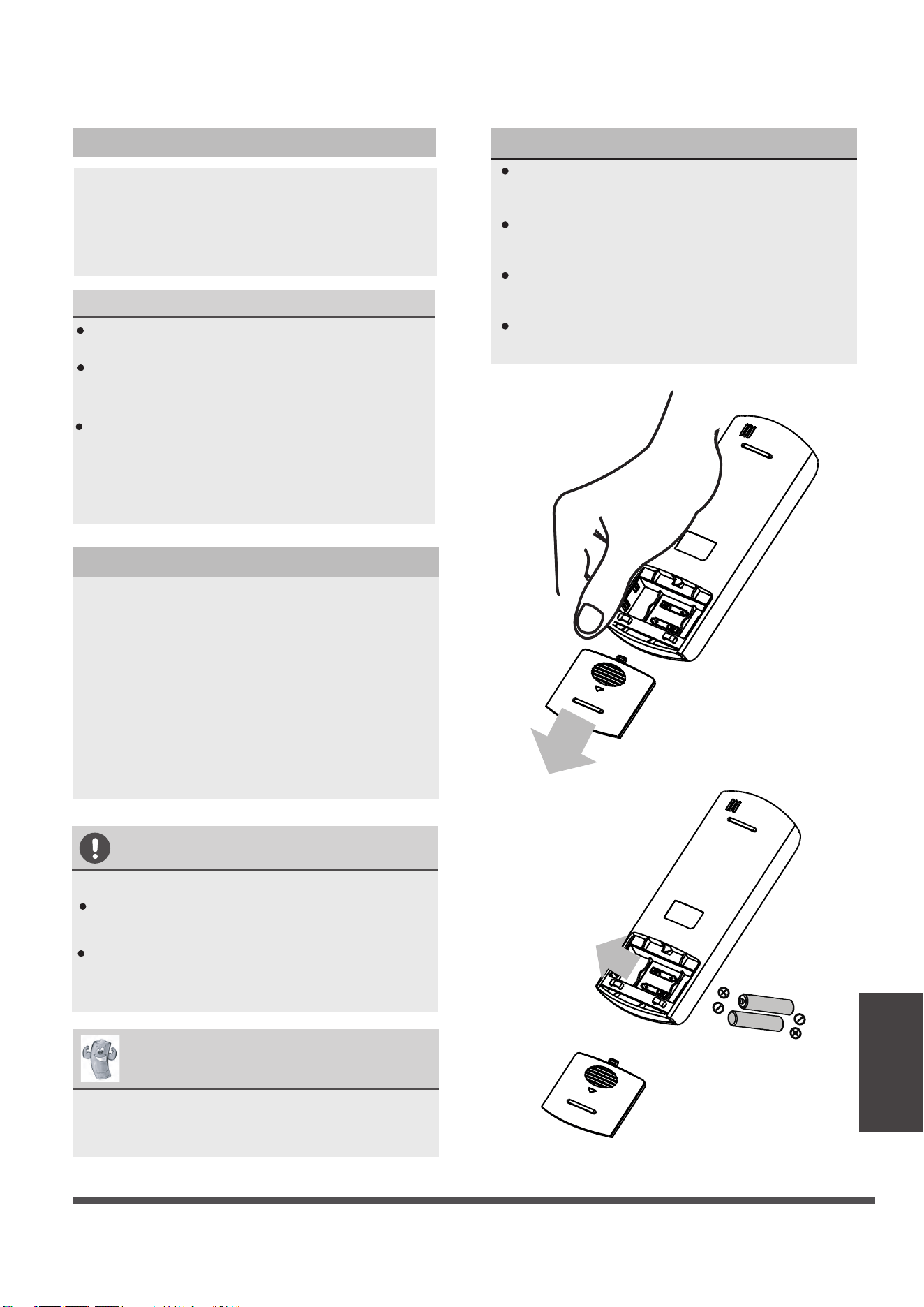
Inserting and Replacing Batteries
Your air conditioning unit comes with two AAA
batteries. Put the batteries in the remote
controller before use.
1. Slide the back cover from the remote
controller downward, to expose the battery
compartment.
2. Insert the batteries, making sure to match
up the (+) and (-) ends of the batteries with
the symbols inside the battery compartment.
3. Slide the battery cover back into place.
BATTERY NOTES
For optimum product performance:
Do not mix old and new batteries, or
batteries of different makes.
Do not leave batteries in the remote
controller if not planning to use device for
more than 2 months.
BATTERY DISPOSAL
Do not dispose of batteries as unsorted
municipal waste. Refer to local laws for
proper disposal of batteries.
,
Handling the Remote Controller
Page 25
Remote Controller
Illustration
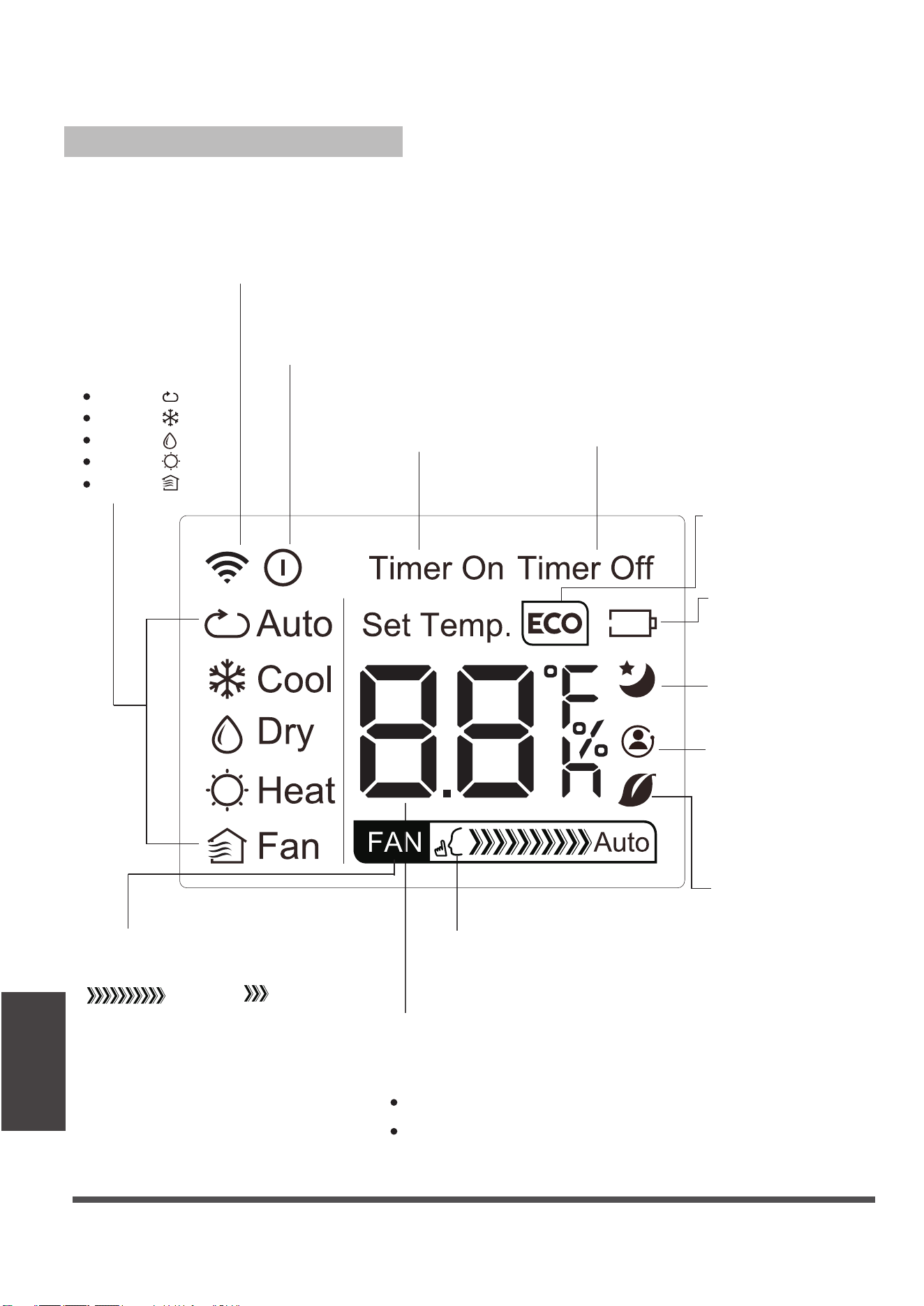
MODE display
Displays the current
mode, including:
AUTO
COOL
DRY
HEAT
FAN
Transmission indicator
Lights up when the remote sends
asignal to the unit.
ON/OFF display
Appears when the unit is turned on
and disappears when it is turned off.
TIMER ON display
Displays when TIMER
ON is set.
TIMER OFF display
Displays when TIMER
OFF is set.
SLEEP display
Battery display
SILENT display
ECO display
Displays when
the SLEEP function
is activated
FAN SPEED display
Displays the selected FAN SPEED:
HIGH
or LOW.
This display is blank when
set to AUTO speed.
Temperature/Timer display
Displays the set temperature by default or timer setting
when using TIMER ON/OFF functions:
o O O
Temperature range: 17-30 C (62 F-86 F)
Timer setting range: 0-24 hours.
This display is blank when operating in FAN mode.
Not available for this unit.
Not available for
this unit.
Not available for
this unit.
Low battery
detection.
FOLLOW ME
Temperature
sensing and
room temperature
display button.
Remote LED Screen Indicators
Page 26
Remote Controller
Illustration
1. Press the MODE button to select the
COOL mode.
2. Set your desired temperature using
the Temp or Temp button.
3. Press the FAN button to select the
fan speed: AUTO, LOW or HIGH.
4. Press the ON/OFF button to start the
unit.
In Auto mode, the unit will automatically
select the COOL, FAN, or DRY mode
based on the set temperature.
1. Pr
mode.
ess the MODE button to select Auto THE
2. Set your desired temperature using the
Temp or Temp button.
3. Press the ON/OFF button to start the unit.
NOTE: FAN SPEED cannot be set in Auto mode.
SETTING THE TEMPERATURE
The operating temperature range for units is
O O O
17-30 C (62 F-86 F). You can increase or
O O
decrease the set temperature in 1 C (1 F)
increments.
How to Use the Basic Functions
COOL Operation
AUTO Operation
1
3
2
1
3
2
4
Page 27
Remote Controller
Illustration
1. Press the MODE button to select the DRY
mode.
2. Set your desired temperature using the
Temp or Temp button.
3. Press the ON/OFF button to start the unit.
NOTE: FAN SPEED cannot be changed in
DRY mode.
1. Press the MODE button to select the FAN
mode.
2. Press the FAN button to select the fan
speed: AUTO, LOW, or HIGH.
3. Press the ON/OFF button to start the
unit.
NOTE: The temperature cannot be set in
FAN mode. As a result, your remote
controller' s LCD screen will not display
the temperature.
How to Use the Basic Functions
FAN Operation
DRY Operation (dehumidifying)
1
3
2
1
2
3
Page 28
Remote Controller
Illustration
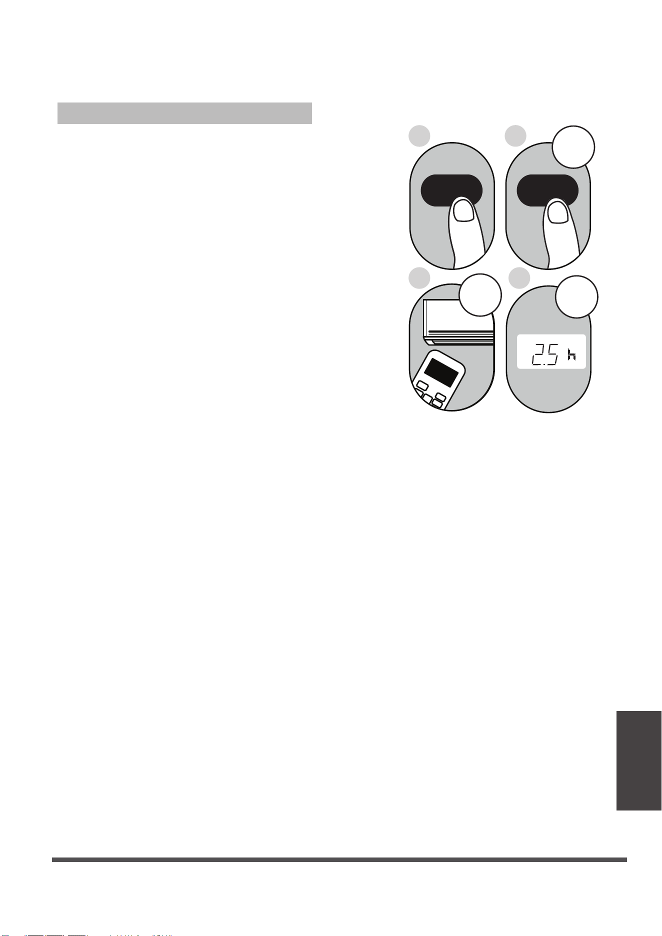
2. Press the TIMER ON button repeatedly
to set the time when you want the unit to
turn on.
3. Wait 2 seconds, then the TIMER ON
function will be activated. Your remote
controller digital display will then go back
to the temperature display.
Example
hours.
: Unit set to turn on after 2.5
2 s
ON/OFF
MODE
FAN
SHORT
CUT
TIMER ON
TIMER OF
F
TEMP
S
L
E
EP
1 s
x5
1
3
2
4
1.
This number indicates the
amount of time after the current time
that you want the unit to turn on.
For example, if you set TIMER ON for
2 hours (2.0 h) will appear on the
screen and the unit will turn on after
2 hours.
Press the TIMER ON button. By
default, the last time period that you
set and an "h" (indicating hours) will
appear on the display.
Note:
TIMER ON Function
The TIMER ON function allows you to set
a period of time after which the unit will
automatically turn on, for instance when
you come home from work.
Your air conditioning unit has two
timer-related functions:
TIM
ER ON- sets the amount of time after
which the unit will automatically turn on.
TIMER OFF- sets the amount of time after
which the unit will automatically turn off.
TIMER ON TIMER ON
Setting the TIMER Function
Page 29
Remote Controller
Illustration
NOTE: When setting the TIMER ON or
TIMER OFF functions up to 10 hours,
the time will increase in 30-minute
increments with each press. After 10
hours and up to 24 hours, it will increase
in 1-hour increments. The timer will revert
to zero after 24 hours.
You can turn off either function by
setting the timer to 0.0h.
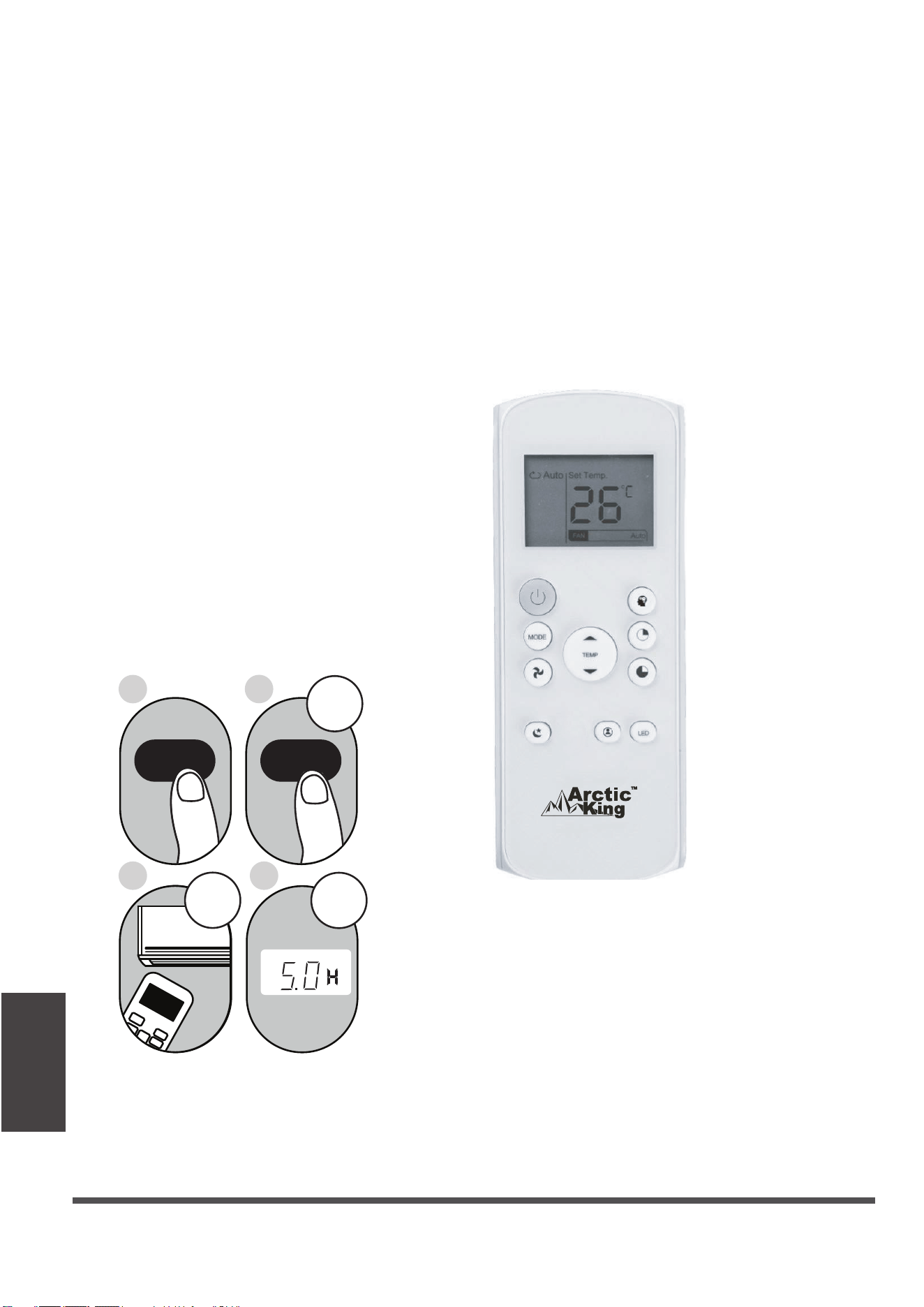
2. Press the TIMER OFF button repeatedly
to set the time when you want the unit to
turn off.
3. Wait 2 seconds, then the TIMER OFF
function will be activated. Your remote
controller digital display will then go back
to the temperature display.
Example
hours.
: Unit set to turn off after 5
TIMER OFF Function
The TIMER OFF function allows you to
set a period of time after which the unit
will automatically turn off for instance when
you wake up.
1.
This number indicates the
amount of time after the current time
that you want the unit to turn off.
For example, if you set TIMER OFF for
2 hours (2.0 h) will appear on the screen
and the unit will turn off after 2 hours.
Press the TIMER OFF button. By
default, the last time period that you
set and an "h" (indicating hours) will
appear on the display.
Note:
2 s
x10
ON/OFF
MODE
F
AN
SHORT
CUT
TIMER ON
TIMER OF
F
TEMP
S
L
EEP
1 s
1
3
2
4
TIMER OFF
TIMER OFF
Continue to press
TIMER ON
or
TIMER OFF until
the desired time is
reached.
Page 30
Remote Controller
Illustration
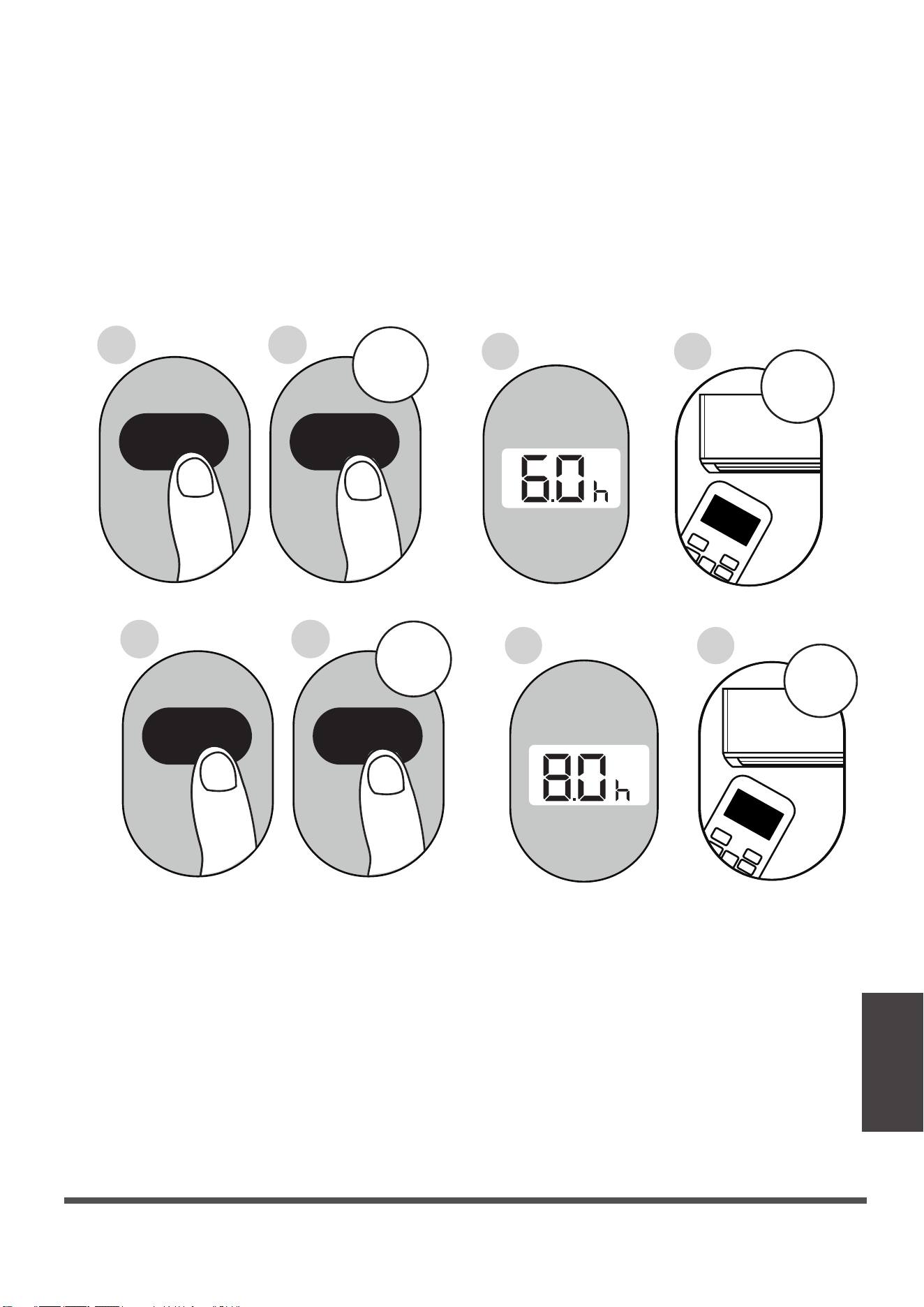
Setting TIMER ON and TIMER OFF at the Same Time
Keep in mind that the time periods you set for both functions refer to hours after the
current time. For example, if the current time is 1:00 PM and you want the unit
to turn on automatically at 7 PM, operate for 2 hours, and automa-tically turn off at
9 PM, do the following:
ON/OFF
ON/OFF
MODE
MODE
SHORT
SHORT
CUT
CUT
TIMER ON
TIMER ON
TEMP
TEMP
3sec
3sec
4
8
3
7
X12
X16
2
6
1
5
TIMER ON
TIMER ON
TIMER OFF
TIMER OFF
Page 31
Remote Controller
Illustration
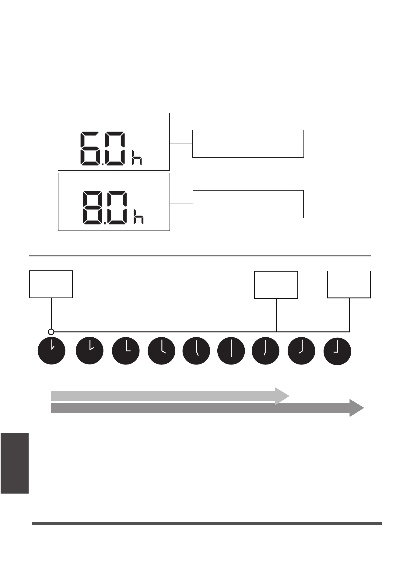
Example: Setting the unit to turn on after 6 hours, operate for 2 hours, then turn off
(see the figure below).
Your remote display
Timer is set to turn ON
6 hours from the current time
Timer is set to turn OFF
8 hours from the current time
Current
time 1PM
2PM 3PM
4PM 5PM
6PM 7PM 8PM 9PM
Timer starts
Unit turns Unit turns
ON
OFF
6 hours later
8 hours later
Timer on
Timer off
Page 32
Remote Controller
Illustration
How to Use the Advanced Functions
SHORTCUT function
The SLEEP function is used to decrease
energy use while you sleep (and don t need
the same temperature settings to stay
comfortable). This function can only be
activated via remote control.
Note: The SLEEP function is not available
in FAN or DRY mode.
,
Used to restore the current settings or resume
previous settings.
Push this button when remote controller is on,
the system will automatically revert back to
the previous settings including operating mode,
setting temperature, fan speed level and sleep
feature (if activated).
If pushing more than 2 seconds, the system
will automatically restore the current operation
settings including operating mode, setting
temperature, fan speed level and sleep
feature(if activated ).
SLEEP Function
The FOLLOW ME function enables the
remote control to measure the temper-
ature at its current location. When using
AUTO, COOL, or HEAT functions,
measuring ambient temperature from
the remote control (instead of from the
indoor unit itself) will enable the air
conditioner to optimize the temperature
around you and ensure maximum comfort.
1. Press FOLLOW ME button to activate
function. The remote control will send
temperature signal to the unit every
three minutes.
2. Press FOLLOW ME button again to
turn off this function.
FOLLOW ME function
Page 33
Remote Controller
Illustration
NOTE:
-Buttons design is based on a typical model and may be slightly different
from the actual unit you purchased. In such case, actual unit buttons shall
-All the functions described are accomplished by the unit. Inoperative features
on the unit.
-If the function description in the OPERATOR'S MANUAL and "Remote
Controller Illustration" is significantly different, the description in the
OPERATOR'S MANUAL shall prevail.
-The device complies with the local national regulations. In Canada,
it complies with CAN ICES-3(B)/NMB-3(B). In the USA, it complies
-This equipment has been tested and meets the limits for a Class-B
digital device, pursuant to part 15 of the FCC Rules. These limits are
designed to provide reasonable protection against harmful interference
in a residential installation. This equipment generate
s, uses, and can
radiate radio frequency energy and, if not installed and used in
accordance with the instructions, may cause harmful interference to
radio communications. However, there is no guarantee that interference
will not occur in a particular installation. If this equipment does cause
harmful interference to radio or television reception, which can be
determined by turning the equipment off and on, the user is encouraged
to try to correct the interference by one or more of the following measures:
R
eorient or relocate the receiving antenna.
Increase the distance between the equipment and receiver.
Connect the equipment into an outlet on a circuit different from the
receiver to which it is connected.
Consult the dealer or an experienced radio/TV technician for help.
Changes or modifications not approved by the compliance party may
v
oid the suer’s authority to operate the equipment.
prevail.
with part 15 of the FCC Rules. Operation is subject to the following
two conditions: (1) This device may not cause harmful interfe-rence
and (2) this device must accept any interference received, including
interference that may cause undesired operation.
Page 34
Remote Controller
Illustration

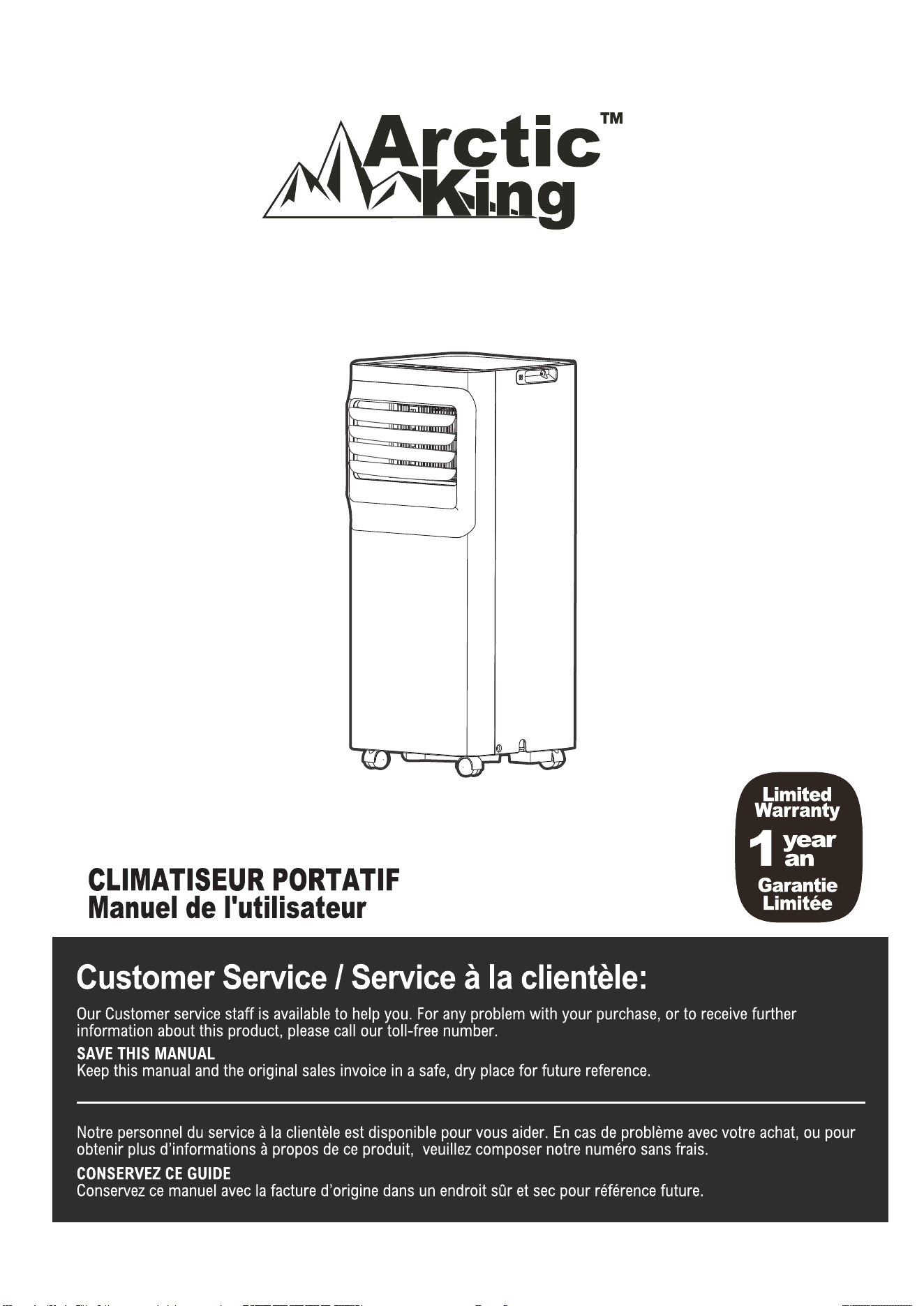
Air Conditioner Limited Warranty
These products have been made to quality standards and are guaranteed for domestic use
against manufacturing faults.
One (1) year full warranty from original purchase date and limited 2nd through 5th year
sealed system warranty if used for normal domestic purposes.
This warranty does not affect your statutory rights. In case of any malfunction of your
product (failure, missing part, etc.), please contact one of our service technicians at our toll-
free service line at 1-888-365-2230 from 8 AM to 6 PM EST, Monday to Friday, and 8 AM to 4
PM EST, Saturday. Midea reserves the right to repair or replace the defective product, at its
discretion.
Any warranty is invalid if the product has been overloaded or subject to neglect, improper
use or an attempted repair other than by an authorized agent. Heavy-duty or daily
professional/commercial usage are not guaranteed. Due to continuous product
improvement, we reserve the right to change product specifications without prior notice.
For instructions on how to properly drain Freon, please contact our customer service at
1-888-365-2230. Thank you.
Page 35

1-888-365-2230
Ref. 21615112 Modèle NO. AAPA06R5RWT

Sommaire
Précautions de Sécurité .........................................................................................................................3
Guide d’Installation.. ..............................................................................................................................12
Utilisation ..............................................................................................................................................17
Guide de drainage
...............................................................................................................................19
Nettoyage et entretien .........................................................................................................................20
Instructions pour la télécommande.........................................................................................................22
Conseils de Dépannage..........................................................................................................................21
Garantie limitée pour l'air conditionné.....................................................................................................34
Page 3
Veuillez lire les mesures de sécurité avant d'utiliser et d'installer l'appareil.
Les instructions suivantes doivent être respectées afin d'éviter que l'utilisateur
ou d'autres personnes ne soient tués ou blessés et que des dommages matériels
ne soient causés.
Un fonctionnement incorrect dû au non-respect des instructions peut entraîner
la mort, des blessures ou des dommages matériels.
ATTENTION
• L'installation doit être effectuée conformément aux instructions d'installation.
Une installation incorrecte peut entraîner des fuites d'eau, des décharges
électriques ou un incendie.
• Utilisez uniquement les accessoires et les pièces fournis, ainsi que les outils
indiqués pour l'installation. L'utilisation de pièces non conformes aux normes
peut entraîner des fuites d'eau, des décharges électriques, des incendies, des
blessures ou des dommages matériels.
• Assurez-vous que la prise de courant que vous utilisez est mise à la terre et
que la tension est appropriée. Le cordon d'alimentation est équipé d'une fiche
de mise à la terre à trois broches pour vous protéger contre les électrocutions.
Les informations relatives à la tension figurent sur la plaque signalétique de
l'appareil.
• Votre appareil doit être utilisé dans une prise murale correctement mise à la
terre. Si la prise murale que vous avez l'intention d'utiliser n'est pas
correctement mise à la terre ou protégée par un fusible temporisé ou un
disjoncteur (le fusible ou le disjoncteur nécessaire est déterminé par le
courant maximum de l'appareil. Le courant maximal est indiqué sur la
plaque signalétique de l'appareil), demandez à un électricien qualifié d'installer
la prise de courant appropriée.
• Installez l'appareil sur une surface plane et solide. Le non-respect de cette
consigne peut entraîner des dommages ou des bruits et vibrations excessifs.
• L'appareil doit être maintenu libre de toute obstruction afin d'assurer son bon
fonctionnement et de réduire les risques pour la sécurité.
• Ne modifiez pas la longueur du cordon d'alimentation et n'utilisez pas de
rallonge pour alimenter l'appareil.
• Ne partagez pas une même prise avec d'autres appareils électriques. Une
mauvaise alimentation électrique peut provoquer un incendie ou une
électrocution.
• N'installez pas votre climatiseur dans une pièce humide telle qu'une salle de
bain ou une salle de lavage. Une trop grande exposition à l'eau peut
provoquer un court-circuit des composants électriques.
• N'installez pas l'appareil dans un endroit susceptible d'être exposé à des gaz
combustibles, car cela pourrait provoquer un incendie.
• L'appareil est équipé de roulettes pour faciliter son déplacement. Veillez à ne
pas utiliser les roulettes sur une moquette épaisse ou pour rouler sur des
objets, car elles risquent de faire basculer l'appareil.
• N'utilisez pas un appareil qui est tombé ou qui a été endommagé.
• L'appareil avec chauffage électrique doit être éloigné d'au moins 1 mètre des
matériaux combustibles.
• Ne touchez pas l'appareil avec des mains mouillées ou humides ou lorsque
vous êtes pieds nus.
ATTENTION
ATTENTION
Ce symbole indique la possibilité de blessures ou de pertes
de vies humaines.
Ce symbole indique la possibilité de dommages matériels
ou de conséquences graves.
Page 4
• Si le climatiseur est renversé en cours d'utilisation, éteignez-le et
débranchez-le immédiatement. Inspectez visuellement l'appareil pour vous
assurer qu'il n'est pas endommagé. Si vous pensez que l'appareil a été
endommagé, contactez un technicien ou le service clientèle pour obtenir
de l'aide.
• En cas d'orage, l'alimentation électrique doit être coupée pour éviter que
l'appareil ne soit endommagé par la foudre.
• Votre climatiseur doit être utilisé de manière à être protégé de l'humidité
(condensation, éclaboussures d'eau, etc.). Ne placez pas ou ne rangez pas
votre climatiseur dans un endroit où il pourrait tomber ou être immergé
dans l'eau ou tout autre liquide.
Débranchez-le immédiatement si cela se produit.
• Tout le câblage doit être effectué en stricte conformité avec le schéma de
câblage situé à l'intérieur de l'appareil.
• La carte de circuit imprimé (PCB) de l'appareil est conçue avec un fusible
pour assurer une protection contre les surintensités. Les caractéristiques du
fusible sont imprimées sur la carte de circuit imprimé : T 3,15A/250V, etc.
• Lorsque la fonction d'évacuation de l'eau n'est pas utilisée, maintenez
fermement les bouchons de vidange supérieur et inférieur sur l'appareil afin
d'éviter tout risque d'ingestion. Lorsque le bouchon de vidange n'est pas
utilisé, conservez-le soigneusement pour éviter que les enfants ne s'étouffent.
• Cet appareil n'est pas destiné à être utilisé par des personnes (y compris des
enfants) dont les capacités physiques, sensorielles ou intellectuelles sont
réduites ou qui manquent d'expérience et de connaissances, à moins qu'elles
n'aient reçu une surveillance ou des instructions concernant l'utilisation de
l'appareil de la part d'une personne responsable de leur sécurité. Les enfants
doivent être surveillés afin de s'assurer qu'ils ne jouent pas avec l'appareil.
Les enfants doivent être surveillés à proximité de l'appareil à tout moment.
(en vigueur dans les autres pays, à l'exception des pays européens)
• Si le cordon d'alimentation est endommagé, il doit être remplacé par le
fabricant, son agent de service ou des personnes de qualification
équivalente afin d'éviter tout danger.
• Avant tout nettoyage ou autre entretien, l'appareil doit être débranché du
réseau électrique.
• Ne retirez pas les couvercles fixes. N'utilisez jamais cet appareil s'il ne
fonctionne pas correctement, s'il est tombé ou s'il a été endommagé.
• Ne pas faire passer le cordon sous la moquette. Ne couvrez pas le cordon
avec des tapis, des patins ou des revêtements semblables. Ne faites pas
passer le cordon sous les meubles ou les appareils. Placez le cordon à l'écart
des zones de circulation et à un endroit où l'on ne risque pas d'y trébucher.
• Ne faites pas fonctionner l'appareil si le cordon, la fiche, le fusible ou le
disjoncteur est endommagé. Mettez l'appareil au rebut ou renvoyez-le à un
centre de service agréé pour qu'il soit examiné ou réparé.
• Pour réduire les risques d'incendie ou d'électrocution, n'utilisez pas cet
appareil avec un dispositif de contrôle de la vitesse à semi-conducteurs.
• L'appareil doit être installé conformément aux réglementations nationales
en matière de câblage.
• Contactez le technicien agréé pour la réparation ou l'entretien de cet appareil.
• Contactez l'installateur agréé pour l'installation de cet appareil.
• Ne couvrez pas et n'obstruez pas les grilles d'entrée et de sortie d'air.
• N'utilisez pas cet appareil pour des fonctions autres que celles décrites dans
ce manuel d'instructions.
• Avant de procéder au nettoyage, mettez l'appareil hors tension et
débranchez-le.
ATTENTION
ATTEBTUIB
Page 5
• Débranchez l'appareil si des sons étranges, des odeurs ou de la fumée s'en
dégagent.
• N'appuyez pas sur les boutons du panneau de commande avec autre chose
que vos doigts.
• Ne retirez pas les couvercles fixes. N'utilisez jamais cet appareil s'il ne
fonctionne pas correctement, s'il est tombé ou s'il a été endommagé.
• Ne faites pas fonctionner ou n'arrêtez pas l'appareil en insérant ou en retirant
la fiche du cordon d'alimentation.
• N'utilisez pas de produits chimiques dangereux pour nettoyer ou entrer en
contact avec l'appareil. N'utilisez pas l'appareil en présence de substances ou
de vapeurs inflammables telles que l'alcool, les insecticides, l'essence, etc.
• Transportez toujours votre climatiseur en position verticale et placez-le sur
une surface stable et plane pendant l'utilisation.
• Contactez toujours une personne qualifiée pour effectuer les réparations. Si le
cordon d'alimentation endommagé, il doit être remplacé par un cordon
d'alimentation neuf obtenu auprès du fabricant du produit et non réparé.
• Tenez la fiche par la tête lorsqu'elle est débranchée.
• Mettez l'appareil hors tension lorsqu'il n'est pas utilisé.
ATTEBTUIB
Électronique
AVERTISSEMENT:
BEFORE PERFORMING ANY ELECTRICAL OR WIRING WORK, TURN OFF THE
MAIN POWER TO THE SYSTEM.
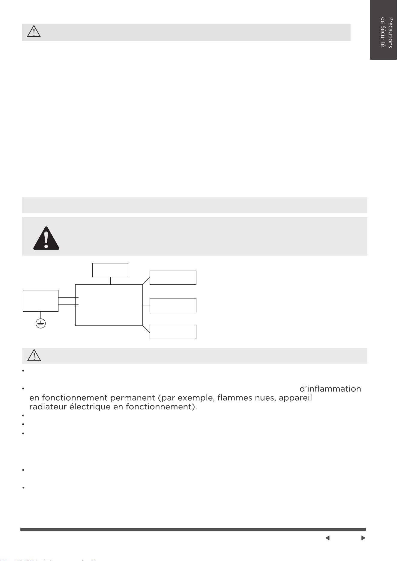
REMARQUE: Veuillez suivre strictement
l'étiquette de câblage attachée à la machine
pour toutes les connexions de câblage. Le
schéma de câblage peut varier pour
différentes unités.Veuillez vous référer au
schéma de câblage sur la machine que vous
avez achetée. Le schéma de câblage ci-dessus
est une version simplifiée à des fins
d'illustration préliminaire uniquement.
Commande Principal
Compresseur
Moteur de
Ventilateur
Écran
Alimentation
L/AC L/L1/L-IN
N/AC N/L2/N-IN
Autre
AVERTISSEMENT concernant l'utilisation du réfrigérant R32
N'utilisez pas d'autres moyens pour accélérer le processus de dégivrage ou pour
nettoyer que ceux recommandés par le fabricant.
L'appareil doit être stocké dans une pièce dépourvue de sources
à gaz ou
Ne le percez pas et ne le brûlez pas.
Sachez que les réfrigérants peuvent ne pas avoir d'odeur.
L'appareil doit être installé, utilisé et stocké dans une pièce dont la surface au
sol correspond à la quantité de réfrigérant à charger. Pour obtenir des
informations précises sur le type de gaz et la quantité, veuillez vous référer à
l'étiquette apposée sur l'appareil.
En cas de différences entre l'étiquette et le manuel concernant la description de la
surface minimale de la pièce, c'est la description de l'étiquette qui prévaut.
L'appareil doit être installé, utilisé et stocké dans une pièce dont la surface au sol
est supérieure à 4 m
2
.
L'appareil ne doit pas être installé dans un espace non ventilé, si cet espace est
inférieur à 4 m
2
.
Page 6
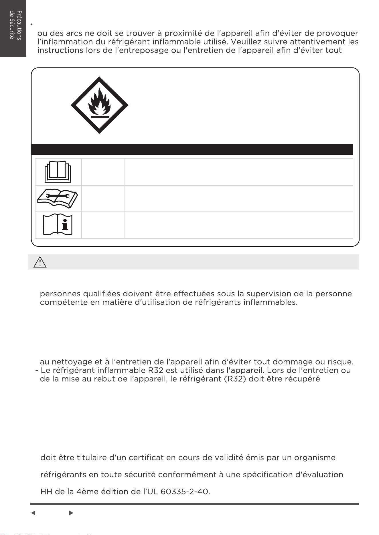
ATTENTION:
Risque d'incendie/
matières inflammables.
Explication des symboles affichés sur l'appareil
MISE EN
GARDE
MISE EN
GARDE
MISE EN
GARDE
Ce symbole indique que le manuel d'utilisation doit être lu
attentivement.
Ce symbole indique que le personnel d'entretien doit
manipuler l'appareil en se référant au manuel d'installation.
Ce symbole indique que des informations sont disponibles,
comme le manuel d'utilisation ou le manuel d'installation.
Aucun feu ouvert ou dispositif tel qu'un interrupteur pouvant générer des étincelles
dommage mécanique.
AVERTISSEMENT
- L'entretien ne doit être effectué que selon les recommandations du fabricant de
l'équipement. L'entretien et les réparations nécessitant l'assistance d'autres
- NE MODIFIEZ PAS la longueur du cordon d'alimentation ni n'utilisez une rallonge
pour alimenter l'appareil.
- NE PARTAGEZ PAS une même prise de courant avec d'autres appareils
électriques. Une alimentation électrique inadéquate peut provoquer un incendie
ou une décharge électrique.
- Suivez attentivement les instructions relatives à la manipulation, à l'installation,
correctement et ne doit pas être rejeté directement dans l'air.
- Les réglementations nationales en matière de gaz doivent être respectées.
- Les ouvertures d'aération ne doivent pas être obstruées.
- L'appareil doit être entreposé de manière à éviter tout dommage mécanique.
Un avertissement indiquant que l'appareil doit être entreposé dans un endroit
bien aéré où la taille de la pièce correspond à la surface de la pièce indiquée
pour le fonctionnement.
- Toute personne appelée à travailler sur un circuit de réfrigération ou à y pénétrer
d'évaluation accrédité par 'industrie, qui atteste de sa capacité à manipuler des
reconnue par l'industrie. Toute formation doit suivre les exigences de l'ANNEXE
A2L
Page 7
Les exemples de procédures de travail sont les suivants:
- l'ouverture de composants scellés
- ouverture d'enceintes aérées
Consultez les réglementations en matière de transport.
1. Transport d'équipements contenant des réfrigérants inflammables
Consultez les réglementations locales.
2. Marquage de l'équipement à l'aide de panneaux
Consultez les réglementations nationales.
3. Élimination des équipements utilisant des réfrigérants inflammables
Le stockage de l'appareil doit être conforme aux réglementations ou instructions
applicables, selon ce qui est le plus strict.
4. Entreposage des équipements et des appareils
La protection des emballages d'entreposage doit être conçue de manière à ce que
les dommages mécaniques subis par l'équipement à l'intérieur de l'emballage
n'entraînent pas de fuite de la charge de fluide frigorigène.
Le nombre maximum de pièces d'équipement pouvant être entreposées à
l'intérieur de l'emballage doit être fixé par la réglementation locale.
5. Entreposage d'équipements emballés (invendus)
Si une réparation du système de réfrigération est nécessaire, les précautions
suivantes doivent être respectées avant d'effectuer des travaux sur le système.
Avant de commencer à travailler sur des systèmes contenant des réfrigérants
système.
pendant l'exécution des travaux.
Tout le personnel d'entretien et les autres personnes travaillant dans la zone locale
doivent être informés de la nature des travaux effectués.
travail doit être délimitée.
Il convient de s'assurer que les conditions à l'intérieur de la zone ont été rendues
6. Informations sur l'entretien
Il convient de s'assurer que l'équipement de détectio des fuites utilisé est adapté
correctement scellé ou qu'il est intrinsèquement sûr.
Si un travail à chaud doit être effectué sur l'équipement de réfrigération ou toute
pièce associée, un équipement d'extinction d'incendie approprié doit être
disponible à portée de main. Un extincteur à poudre ou à CO2 doit se trouver à
proximité de la zone de chargement.
Page 8
Aucune personne effectuant des travaux en rapport avec un système de
réfrigération impliquant l'exposition d'une tuyauterie contenant ou ayant contenu
d'entraîner un risque d'incendie ou d'explosion.
éventuellement être libéré dans l'espace environnant.
Avant le début des travaux, la zone autour de l'équipement doit être examinée
Il convient de s'assurer que la zone est à l'air libre ou qu'elle est correctement
aérée avant de pénétrer dans le système ou d'effectuer un travail à chaud. Une
certaine ventilation doit être maintenue pendant la durée des travaux. La
ventilation doit permettre de disperser en toute sécurité tout réfrigérant libéré et,
de préférence, de l'expulser dans l'atmosphère.
Lorsque des composants électriques sont remplacés, ils doivent être adaptés à
et de maintenance du fabricant doivent être respectées à tout moment.
En cas de doute, consultez le service technique du fabricant pour obtenir de l'aide.
la pièce dans laquelle les pièces contenant du réfrigérant sont installées.
Le marquage de l'équipement reste visible et lisible. Les marquages et les
panneaux qui sont illisibles doivent être corrigés.
risquent pas d'être exposés à une substance susceptible de corroder les éléments
matériaux intrinsèquement résistants à la corrosion ou qu'ils ne soient
convenablement protégés contre la corrosion.
La réparation et l'entretien des composants électriques doivent comprendre des
S'il existe un défaut susceptible de compromettre la sécurité, aucune alimentation
électrique ne doit être connectée au circuit tant que le problème n'a pas été
résolu de manière satisfaisante.
Si le défaut ne peut pas être corrigé immédiatement, mais qu'il est nécessaire
de poursuivre le travail, une solution temporaire adéquate doit être adoptée.
comprendre: Les condensateurs sont déchargés: cette opération doit être
Qu'aucun composant ou câblage électrique sous tension n'est exposé pendant
la charge, la récupération ou la purge du système.
Qu'il y ait un maintien de la mise à la terre.
7. Réparations des composants scellés
8. Réparation des composants à sécurité intrinsèque

Page 9
excessive, à des vibrations, à des rebords tranchants ou à tout autre effet
effets de l'usure ou des vibrations continues provenant de sources telles que
les compresseurs ou les ventilateurs.
9. Cablage
10. Détection des fluides frigorigènes inflammables
Lorsque l'on pénètre dans le circuit de réfrigération pour effectuer des
réparations - ou pour toute autre raison - il convient d'utiliser les procédures
conventionnelles. Toutefois, pour les réfrigérants inflammables, il est important
de suivre des pratiques exemplaires, étant donné que l'inflammabilité est un
facteur à prendre en considération. La procédure suivante doit être
respectée:
-Retirer en toute sécurité le réfrigérant conformément aux réglementations
locales et nationales;
-Évacuer;
-Purger le circuit avec un gaz inerte (optionnel pour A2L);
-Évacuer (optionnel pour A2L).
-Rincer ou purger continuellement avec un gaz inerte lors de l'utilisation d'une
flamme pour ouvrir le circuit; et
-Ouvrir le circuit.
La charge de réfrigérant doit être récupérée dans les bouteilles de récupération
appropriées si la mise à l'air libre n'est pas autorisée par les codes locaux et
nationaux. Pour les appareils contenant des réfrigérants inflammables, le
système doit être purgé avec de l'azote sans oxygène afin de rendre l'appareil
sûr pour les réfrigérants inflammables. Ce processus peut devoir être répété
plusieurs fois. L'air comprimé ou l'oxygène ne doivent pas être utilisés pour
purger les systèmes de réfrigération. Pour les appareils contenant des
réfrigérants inflammables, la purge des réfrigérants doit être réalisée en brisant
le vide dans le système avec de l'azote exempt d'oxygène et en continuant à
remplir jusqu'à ce que la pression de travail soit atteinte, puis en ventilant dans
l'atmosphère, et enfin en tirant au vide (optionnel pour A2L). Ce processus
doit être répété jusqu'à ce qu'il n'y ait plus de réfrigérant dans le système
(optionnel pour A2L).
En aucun cas, des sources potentielles d'inflammation ne doivent être utilisées
pour la recherche ou la détection de fuites de réfrigérants. Un chalumeau aux
halogénures (ou tout autre détecteur utilisant une flamme nue) ne doit pas être
utilisé. Les méthodes de détection des fuites suivantes sont considérées comme
acceptables pour les systèmes contenant des réfrigérants inflammables. Les
détecteurs de fuites électroniques peuvent être utilisés pour détecter les
réfrigérants inflammables, mais leur sensibilité peut être insuffisante ou
nécessiter un recalibrage. (L'équipement de détection doit être calibré dans une
zone exempte de réfrigérant).
Il convient de s'assurer que le détecteur n'est pas une source potentielle
d'inflammation et qu'il est adapté au fluide frigorigène utilisé.
L'équipement de détection des fuites doit être réglé sur un pourcentage de la
LFL du réfrigérant et doit être calibré en fonction du réfrigérant utilisé et le
pourcentage approprié de gaz (25 % au maximum) est confirmé. Les liquides
de détection des fuites conviennent à la plupart des réfrigérants, mais
l'utilisation de détergents contenant du chlore doit être évitée, car le chlore
peut réagir avec le réfrigérant et corroder la tuyauterie en cuivre.
Si une fuite est suspectée, toutes les flammes nues doivent être enlevées/
éteintes. Si une fuite de réfrigérant nécessitant un brasage est constatée, tout
le réfrigérant doit être récupéré dans le système ou isolé (au moyen de vannes
d'arrêt) dans une partie du système éloignée de la fuite.
L'élimination du fluide frigorigène doit se faire conformément à la section
« Enlèvement et évacuation ».
11. Enlèvement et évacuation
Page 10
Lorsque la charge finale d'azote sans oxygène est utilisée, le système doit être
mis à l'air libre jusqu'à la pression atmosphérique pour permettre le travail.
Il convient de s'assurer que la sortie de la pompe à vide ne se trouve pas à
proximité d'une source d'inflammation potentielle et qu'une ventilation est
disponible.
Avant d'effectuer cette procédure, il est essentiel que le technicien connaisse
parfaitement l'équipement et toutes ses caractéristiques. Il est recommandé de
veiller à ce que tous les réfrigérants soient récupérés en toute sécurité. Avant
de procéder à cette opération, un échantillon d'huile et de réfrigérant doit être
prélevé au cas où une analyse serait nécessaire avant la réutilisation du
réfrigérant récupéré.
Il est essentiel que l'alimentation électrique soit disponible avant le début des
opérations.
a) Familiarisez-vous avec l'équipement et son fonctionnement.
b) Isolez le système électriquement.
c) Avant d'entamer la procédure, assurez-vous qu'un équipement de manutention
mécanique est à disposition, au besoin, et qu'il n'y a pas d'autre moyen de le
faire : tous les équipements de protection individuelle sont disponibles et utilisés
correctement; le processus de récupération est supervisé à tout moment par
une personne compétente; l'équipement de récupération et les bouteilles sont
conformes aux normes appropriées.
d) Si possible, vidangez le système de réfrigération par pompage.
e) S'il n'est pas possible de faire le vide, fabriquez un collecteur afin que le
réfrigérant puisse être retiré des différentes parties du système.
f) Assurez-vous que la bouteille se trouve sur la balance avant de procéder à
la récupération.
g) Démarrez le dispositif de récupération et utilisez-le conformément aux
instructions.
h) Ne remplissez pas trop les bouteilles (pas plus de 80 % du volume de la
charge liquide).
13. Mise hors service
12. Procédures de charge
i) Ne dépassez pas la pression de service maximale de la bouteille, même
temporairement.
j) Lorsque les bouteilles ont été correctement remplies et que le processus est
terminé, assurez-vous que les bouteilles et l'équipement sont rapidement retirés
du site et que toutes les vannes d'isolation de l'équipement sont fermées.
k) Le réfrigérant récupéré ne doit pas être chargé dans un autre système de
réfrigération avant d'avoir été nettoyé et vérifié.
L'équipement doit porter une étiquette indiquant qu'il a été mis hors service et
vidé de son fluide frigorigène. L'étiquette doit être datée et signée.
Veillez à ce que l'équipement porte une étiquette indiquant qu'il contient un
réfrigérant inflammable.
14. Étiquetage
Outre les procédures de charge conventionnelles, les exigences suivantes
doivent être suivies. Veillez à ce qu'il n'y ait pas de contamination des différents
fluides frigorigènes lors de l'utilisation de l'équipement de charge. Les tuyaux
ou conduites doivent être aussi courts que possible pour minimiser la quantité
de réfrigérant qu'ils contiennent. Les bouteilles doivent être conservées dans
une position appropriée conformément aux instructions. Assurez-vous que le
système de réfrigération est mis à la terre avant de le charger en fluide
frigorigène. Étiquetez le système lorsque la charge est terminée (si ce n'est pas
déjà fait). Il faut faire très attention à ne pas trop remplir le système de
réfrigération. Avant de recharger le système, il doit être soumis à un essai de
pression avec l'OFN. Le système doit être soumis à un essai d'étanchéité à la
fin de la charge, mais avant la mise en service. Un essai d'étanchéité de suivi
doit être effectué avant de quitter le site.
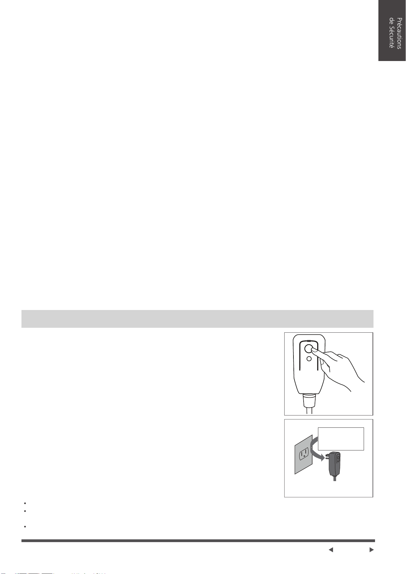
Page 11
Le cordon d'alimentation contient un dispositif permettant
de mesurer du courant; ce dispositif détecte les dommages
au le cordon d'alimentation. Testez votre cordon
d'alimentation d'alimentation comme suit:
1. Branchez le climatiseur.
2. Le cordon d'alimentation doit comporter DEUX boutons
sur la tête de la fiche.
Appuyez sur le bouton TEST. Vous entendrez un clic
lorsque le bouton RESET ressort.
3. Appuyez sur le bouton RESET. Vous entendrez un clic
lorsque le bouton s'enclenche.
4. Le cordon d'alimentation fournit maintenant l'appareil en
électricité. (Sur certains appareils, cela peut être indiqué
par un voyant sur la tête de la fiche).
Le cordon d'alimentation de ce climatiseur contient un
dispositif de détection de courant conçu pour réduire le
risque d'incendie.
Dans le cas où le cordon d'alimentation est endommagé, il
ne peut pas être réparé. Il doit être remplacé par un cordon
approuvé par le fabricant.
Prise murale de type mise à la terre
Ne pas, en aucun cas,
couper, retirer ou
contourner le brin de
mise à la terre.
Cordon d'alimentation avec fiche de mise à
la terre à 3 brins et dispositif de détection
de courant
RESET
TEST
Brancher et
appuyer le bouton
RESET.
Alimentation de l'appareil
REMARQUE
N'utilisez pas ce dispositif pour mettre en marche ou arrêter l'appareil.
REMARQUES
Assurez-vous toujours que le bouton RESET est enclenché pour un
fonctionnement correct.
Le cordon d'alimentation doit être remplacé s'il ne se réinitialise pas lorsque le
bouton TEST est enfoncé. Veuillez contacter le service clientèle.
Lorsque l'on retire le fluide frigorigène d'un système, que ce soit à des fins
d'entretien ou de mise hors service, il est recommandé de veiller à ce que tous
les fluides frigorigènes soient retirés en toute sécurité. Lors du transfert du
fluide frigorigène dans les bouteilles, veillez à n'utiliser que des bouteilles de
récupération de fluide frigorigène appropriées.
Veillez à ce que le nombre de bouteilles nécessaires pour contenir la charge
totale du système soit suffisant. Toutes les bouteilles à utiliser sont désignées
pour le fluide frigorigène récupéré et étiquetées pour ce fluide (c'est-à-dire des
bouteilles spéciales pour la récupération du fluide frigorigène). Les bouteilles
doivent être équipées d'une soupape de surpression et des valves d'arrêt
correspondantes en bon état de fonctionnement. Les bouteilles de récupération
vides sont évacuées et, si possible, refroidies avant la récupération.
L'équipement de récupération doit être en bon état de fonctionnement et
accompagné d'un ensemble d'instructions concernant l'équipement disponible
et adapté à la récupération des réfrigérants inflammables. En outre, un jeu de
balances calibrées doit être disponible et en bon état de fonctionnement. Les
tuyaux doivent être complets, munis de raccords étanches et en bon état.
Avant d'utiliser la machine de récupération, vérifiez qu'elle est en bon état de
fonctionnement, qu'elle a été correctement entretenue et que tous les
composants électriques associés sont scellés afin d'éviter toute inflammation
en cas de fuite de réfrigérant. En cas de doute, consultez le fabricant. Le fluide
frigorigène récupéré doit être renvoyé au fournisseur de fluide frigorigène dans
le bon cylindre de récupération, et le bordereau de transfert de déchets
correspondant doit être établi.
Ne mélangez pas les réfrigérants dans les unités de récupération et surtout pas
dans les bouteilles. Si les compresseurs ou les huiles de compresseur doivent
être retirés, assurez-vous qu'ils ont été évacués à un niveau acceptable afin
de garantir que le réfrigérant inflammable ne reste pas dans le lubrifiant. Le
processus d'évacuation doit être effectué avant de renvoyer le compresseur
aux fournisseurs. Seul le chauffage électrique du corps du compresseur doit
être utilisé pour accélérer ce processus. Lorsque l'huile est vidangée d'un
système, cette opération doit être effectuée en toute sécurité.
15. Récupération
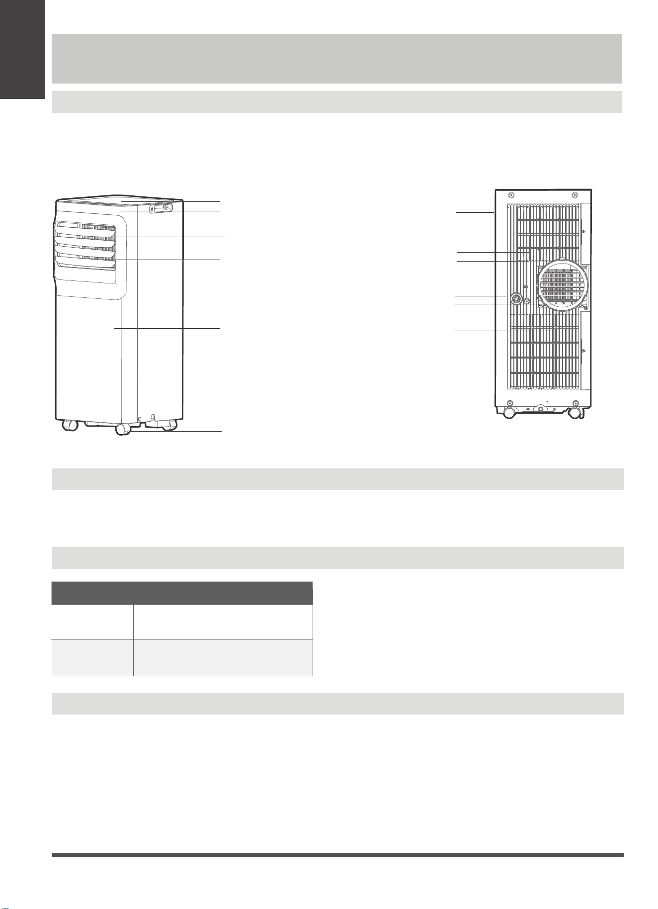
Page 12
Guide
d’Installationn
Guide d’Installation
Préparation
NOTE:
Les illustrations dans le manuel sont à des ns d'explication seulement. Votre machine peut être
légèrement diérente. La forme réelle prévaudra. L’appareil peut être contrôlé par le panneau de
commande seulement ou avec la télécommande.
MODE Plage de Température
Refroidissement De 17 à 35°C (de 60 à 95°F)
Séchage
De13 à 35°C (de 55 à 95°F)
Installation de Tuyau d’Évacuation
Le tuyau d'évacuation et l'adaptateur doivent être installés ou retirés conformément au mode
d'utilisation. Pour les modes REFROIDISSEMENT, CHAUFFAGE (type de chauage par pompe) ou
AUTO, il faut installer le tuyau d’évacuation. Pour les modes VENTILATEUR, SÉCHAGE ou
CHAUFFAGE (type chauage électrique), il faut enlever le tuyau d’évacuation.
Avis de Conception
An de garantir les performances optimales de nos produits, les spécications de
conception de l'appareil et de la télécommande peuvent être modiées sans préavis.
Plage de Température Ambiante pour l’Opération de l'Appareil
commande de volet
levier de réglage manuel
(Sur certains modèles)
Sortie d'air courbée
Panneau de contrôle
Récepteur de signal
à distance
Panneau avant
Roulette
Vue arrière
Poignée
(les deux côtés)
Filtre à air
entrée d'air
supérieure
Sortie d'air
Entrée d'air
inférieure
Sortie de drainage
Plateau inférieur
sortie de drainage
Vue de face
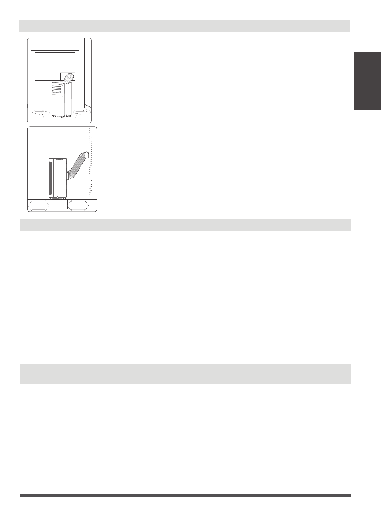
Page 13
Choisir L’Emplacement Correct
Votre emplacement d'installation doit répondre aux exigences suivantes :
-Assurez-vous d’installer votre appareil sur une surface plate an de minimiser
le bruit et les vibrations.
-L'appareil doit être installé à proximité d'une prise mise à la terre et le Drain
du Bac Collecteur (situé à l'arrière de l'appareil) doit être accessible.
-L'appareil doit être placé à au moins 30 cm (12’’) du mur le plus proche pour
assurer une climatisation adéquate. La lame de la persienne horizontale doit
être à au moins 50 cm (19,7’’) des obstacles.
-NE PAS couvrir les Entrées, les Sorties ou le Récepteur de Signal à Distance de
l'appareil, car cela pourrait endommager l'appareil.
Information d’Évaluation Énergétique
Les informations relatives à la consommation énergétique et au bruit de cet appareil reposent sur l’installation
standard utilisant un conduit d’échappement non prolongé (Diamètre: 150 mm, Longueur: 1,5 m) sans
adaptateur de patin d’étanchéité ni adaptateur d’échappement mural A.
L'appareil avec conduit d'évacuation prolongé de 3 mètres fonctionne à l'aide de 2 conduits d'évacuation
(Diamètre : 150 mm, Longueur : 1,5 m + Diamètre : 130mm, Longueur : 1,5 m). L’évaluation de la
consommation énergétique et des informations sur le bruit de l’appareil avec conduit d’évacuation prolongé de
3 mètres n’est pas évaluée (pour certains modèles).
NOTE :
Nous recommandons d’utiliser l’appareil à une température ambiante inférieure à 35°C. Dans la mesure où il
existe un risque que l'appareil avec un conduit d'évacuation prolongé de 3 mètres ne fonctionne pas à une
température ambiante supérieure à 35°C dans certaines conditions extrêmes, telles que la prise d'air inférieure
doit être bloquée à 50%.
Guide
d’Installationn
Comment rester cool avec un nouveau climatiseur portable(Pour les modèles
satisfont aux exigences du ministère de l'énergie aux États-Unis)
En raison d'une nouvelle procédure fédérale d'essai pour les climatiseurs portables, vous pouvez remarquer
que les réclamations de capacité de refroidissement sur les emballages portables de climatiseurs sont
signicativement inférieures à celles des modèles produits avant 2017.Cela est dû aux changements de
procédure d'essai, pas aux climatisateurs portables eux-mêmes.
≥30cm(12’’)
≥50cm
19.7’’
≥50cm
19.7’’
≥30cm(12’’)
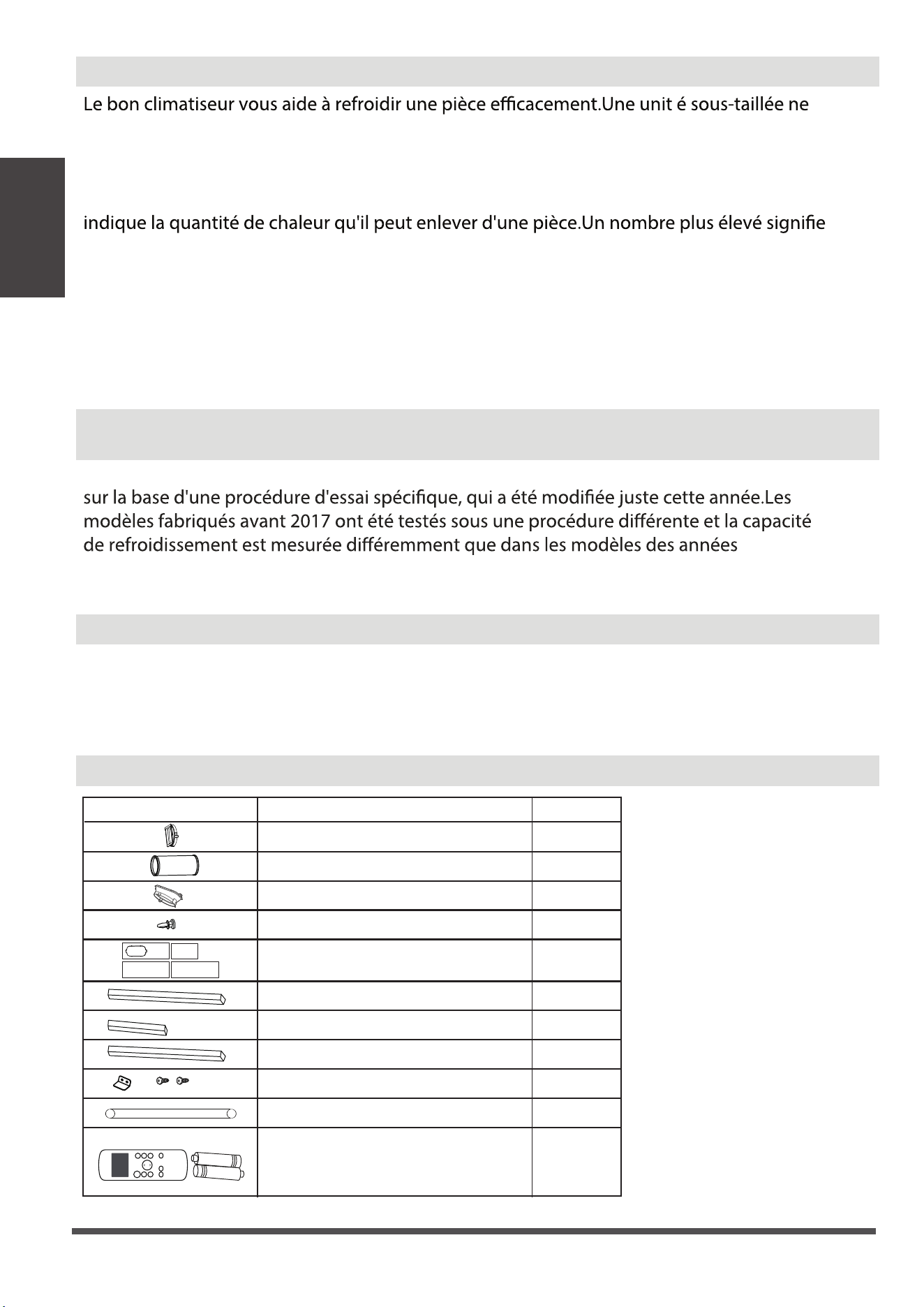
Accessoires
Pièce
Désignation
1 pièces
1 pièces
1 pièces
3 pièces
2 pièces
4 pièces
2 pièces
1 ensemble
1 ensemble
Adaptateur de l'appareil
Battant coulissant de fenêtre
Tuyau d'évacuation
Boulon
Joint en mousse A (adhésif)
Joint en mousse B (adhésif)
Joint en mousse C (non adhésif)
Support de sécurité et 2 vis
Tuyau de drainage
Quantité
1 pièces
O
N
/
O
FF
T
E
M
P
S
HO
R
T
C
U
T
T
I
M
E
R
O
N
T
I
M
E
R
O
F
F
M
O
D
E
F
A
N
S
L
E
E
P
S
W
I
N
G
LE
D
Contrôleur et batterie à distance
(seulement pour les modèles de contrôle
à distance)
Page 14
Guide
d’Installationn
Qu'est-ce que je dois chercher d'abord quand j'achète un climatiseur portable?
se refroidira pas adéquatement alors qu'une trop grande ne supprimera pas assez
d'humidité, laissant l'air se sentir humide.Pour trouver le climatiseur approprié, déterminez
les images carrées de la pièce que vous voulez refroidir en multipliant la longueur de la
pièce par sa largeur.Vous devez aussi connaître la qualité BTU de l'air conditionné, qui
plus d'énergie de refroidissement pour une pièce plus grande.(Soyez sûr que vous ne
comparez que de nouveaux modèles les uns aux autres - les modèles plus anciens
peuvent sembler avoir une capacité plus élevée, mais sont en fait les mêmes).Assurez-
vous de “grandir” si votre climatiseur portable sera placé dans une salle très soleillée, dans
une cuisine ou dans une salle avec des plafonds élevés.Après avoir trouvé la bonne
capacité de refroidissement ou votre chambre, vous pouvez regarder d'autres
caractéristiques.
Pourquoi la capacité de refroidissement est-elle plus faible chez les modèles plus récents
que chez les unités plus anciennes?
Les règlements fédéraux exigent que les fabricants calculent la capacité de refroidissement
précédentes.Alors, alors que les UBT peuvent être plus faibles, la capacité de
refroidissement réelle des climatisateurs n'a pas changé.
Qu'est-ce que SACC ?
SACC est la valeur représentative de la capacité de refroidissement ajustée à la saison, en
Btu/h, déterminée conformément à la procédure d'essai DOE au titre 10 du Code des
Règlements fédéraux (CFR) 430, au sous-article B, à l'appendice CC et aux plans
d'échantillonnage applicables.
Passage d'évacuation d'air
1 ensemble
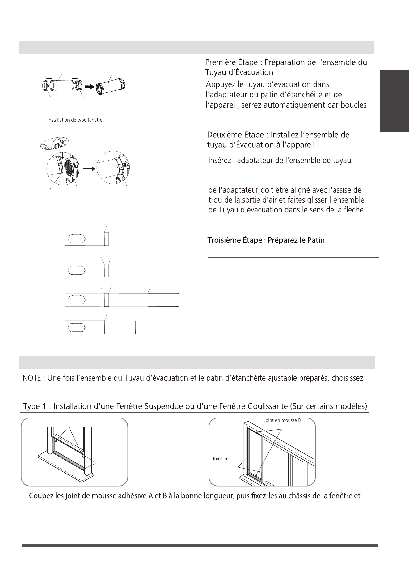
Ou
Joint en mousse B
(Type adhésif plus court)
Joint en
mousse A
(Type adhésif)
Installation
l’une des deux méthodes d’installation suivantes.
1.
au cadre, comme indiqué.
d’Étanchéité Réglable
1. Réglez la taille de patin d’étanchéité
en fonction de la taille de la fenêtre
2. Si la longueur de la fenêtre nécessite deux ou
trois patins d’étanchéité, utilisez le(s)
boulon(s) pour serrer le patin d’étanchéité
jusqu’à ce qu’ils s’ajustent à une taille
appropriée.
mousse A
(Type adhésif)
(Type adhésif plus court)
Page 15
Guide
d’Installationn
Kit d’Installation pour la Fenêtre
Adaptateur
I'appareil
Adaptateur de patin
d'étanchéité
Tuyau d’évacuation
Ensemble de
tuyau d'évacuation
Crochet
Assise de trou
Rainure inférieure
Adaptateur
Assurez-vous que
l'adaptateur est inséré dans
la rainure inférieure de la
sortie d'air.
d'évacuation dans la rainure inférieure de la
sortie d'air de l'appareil tandis que le crochet
pour l'installation.
élastiques des adaptateurs.
1+2:
Boulon
1+2+3:
BoulonBoulon
1+2+3+4:
BoulonBoulonBoulon
1+4:
Boulon
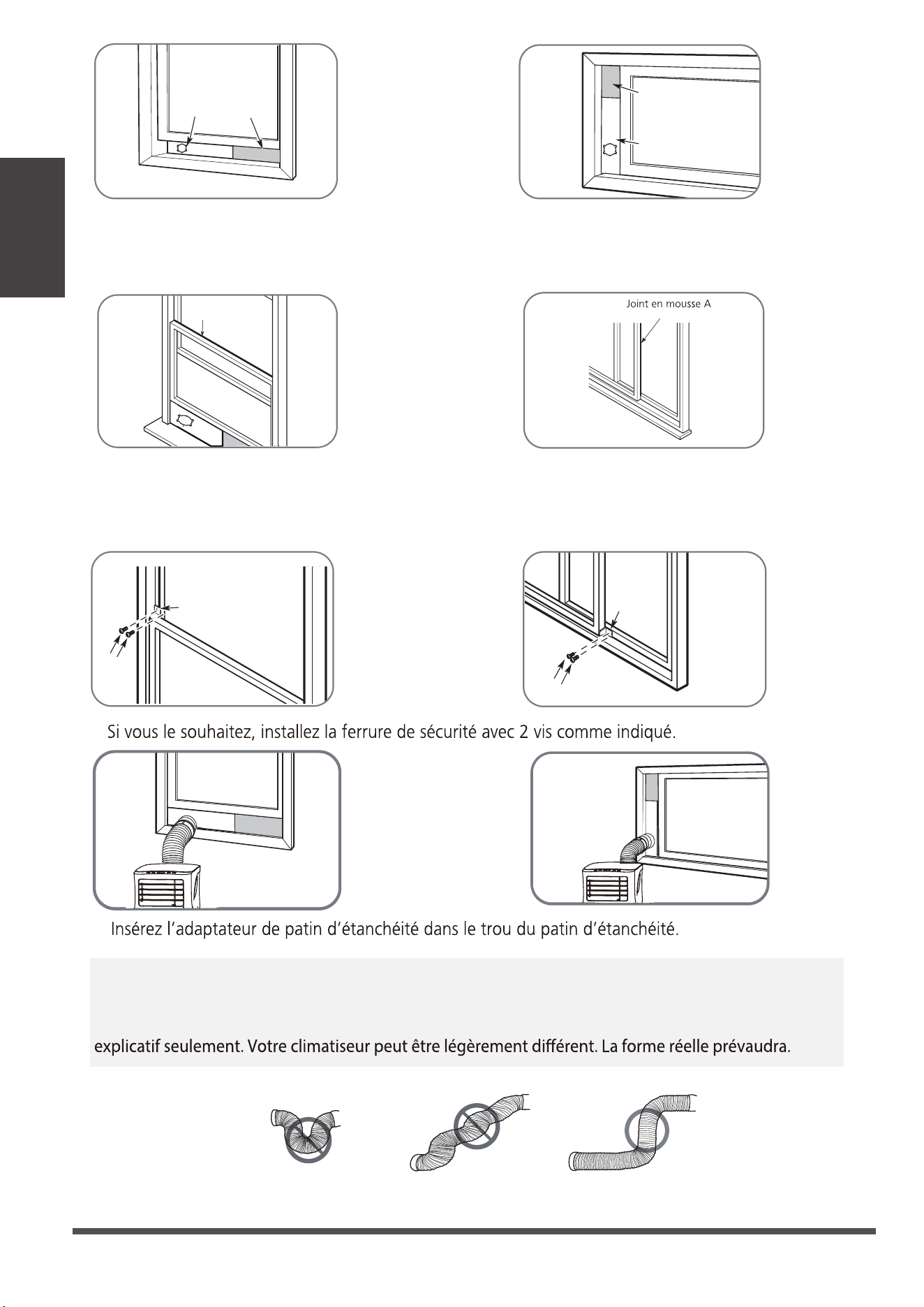
Ou
Ou
2 Vis
Support de sécurité
4.
5.
2 Vis
NOTE : Pour assurer un fonctionnement correct, NE PAS trop étendre ou plier le tuyau. Assurez-vous
qu'il n'y a pas d'obstacle autour de la sortie d'air du tuyau d'évacuation (de l'ordre de 500 mm) pour
que le système d'évacuation fonctionne correctement. Les illustrations de ce manuel ont un but
Support
de sécurité
Page 16
Guide
d’Installationn
Ou
Ou
Battant coulissant
pour la fenêtre A
Joint en mousse A
(Type non adhésif
3. Coupez la bande d’étanchéité de mousse non adhésive C en fonction de la largeur (ou de la hauteur)
de la fenêtre. Insérez la bande d’étanchéité entre le verre et le cadre de la fenêtre pour empêcher l’air et
les insectes de pénétrer dans la pièce.
2. Coupez la joint d’étanchéité de mousse non adhésive C en fonction de la largeur (ou de la hauteur)
de la fenêtre. Insérez la bande d’étanchéité entre le verre et le cadre de la fenêtre pour empêcher l’air
et les insectes de pénétrer dans la pièce.
Battant coulissant
pour la fenêtre B
(Si nécessaire)
Battant coulissant
pour la fenêtre A
Battant coulissant
pour la fenêtre B
(Si nécessaire)
(Type non adhésif
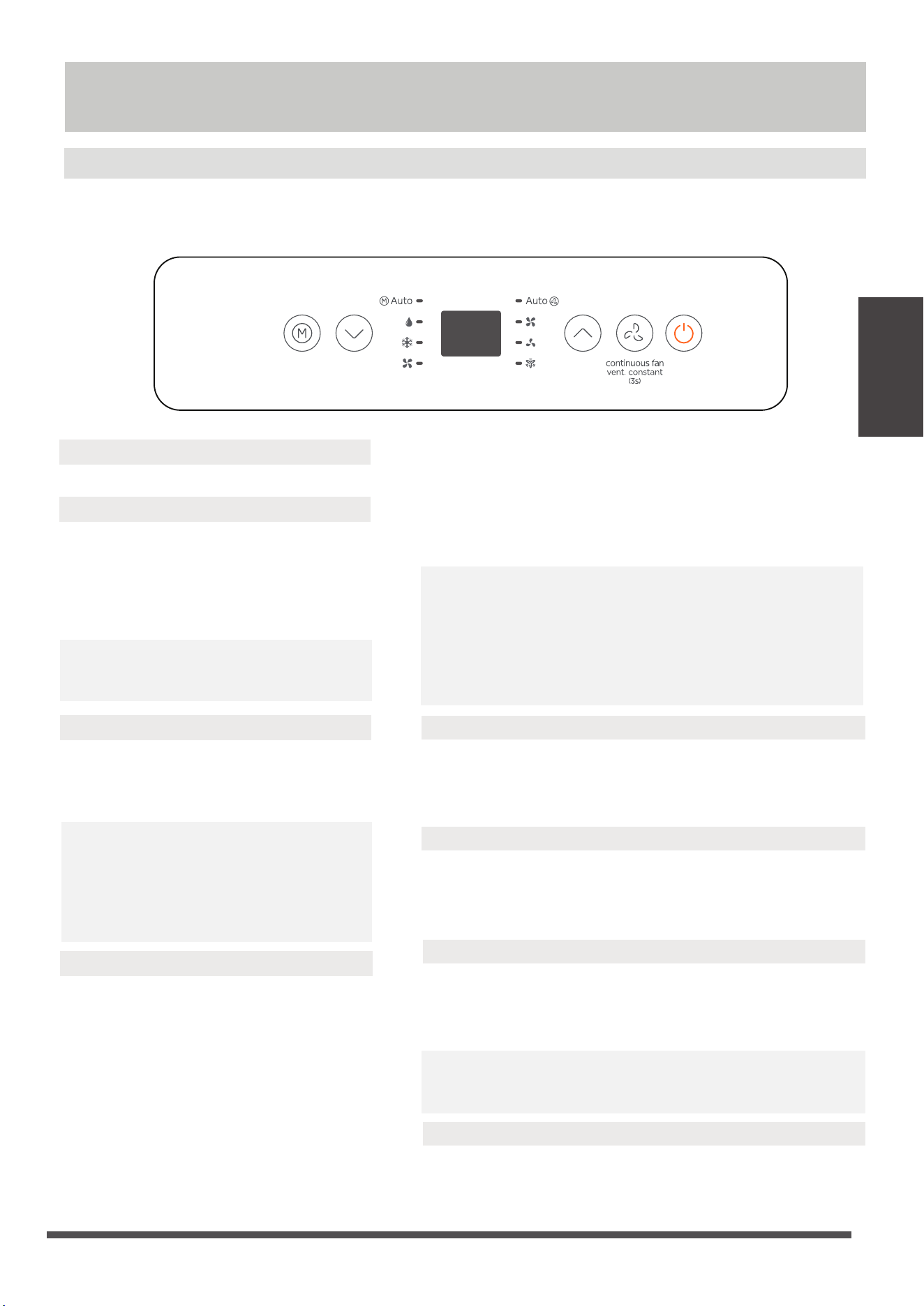
Features du Panel de contrôle
REMARQUE: Les panneaux de contrôle suivants sont destinés uniquement à des fins d'explication.Le
panneau de contrôle de l'unit é que vous avez acheté peut être légèrement différent selon les modèles.
Votre machine ne contient peut-être pas d'indicateurs ou de boutons.La forme réelle va présider.
Utilisation
Page 17
1. Bouton D'ALIMENTATION
2. Fonction MODE
5. Fonction Fan
6. Mode Cool
Ache la température réglée en mode Froid,
ou Auto. Ache la température de la pièce
en mode SEC et VENTILATEUR.
Ache les codes d'erreur
EH00 - Erreur EEPROM.
EH60 - Erreur capteur de température
de la pièce.
EH61 - Erreur capteur de température de
l'évaporateur.
EC52 - Erreur capteur de température du
condenseur (sur certains modèles).
EH0b - Erreur de communication du panneau d'achage.
EC - Détection de fuite de réfrigérant dysfonctionnement
(sur certains modèles).
Ache le code de protection :
P1 - Le bac inférieur est plein - Connectez le tuyau de
vidange et évacuez l'eau collectée.
Si la protection se répète, appelez le service.
REMARQUE : En cas de l'un des dysfonctionnements ci-dessus
se produit, éteignez l'appareil et vériez s'il y obstructions.
Redémarrez l'unité, si le le dysfonctionnement est toujours
présent, éteignez l'appareil et débranchez le cordon
d'alimentation. Contactez le fabricant, ses agents de service
ou une personne qualiée similaire pour le service.
Sélectionne le mode de fonctionnement
approprié. Chaque fois que vous appuyez
sur la touche, le mode est sélectionné
dans une séquence qui va de AUTO, SEC,
COOL et FAN. Le voyant du mode s'allume
sous les diérents réglages du mode.
Interrupteur d'alimentation marche / arrêt.
REMARQUE : En mode AUTO, la vitesse
du VENTILATEUR sera ajustée
automatiquement.
3. Boutons HAUT et BAS
Utilisés pour ajuster (augmenter/diminuer)
les réglages de température par incréments
de 1°C/2°F (ou 1°F) dans une plage de
16°C/60°F à 30°C/88°F (ou 86°F).
REMARQUE : La commande est capable
d'acher la température en degrés
Fahrenheit ou en degrés Celsius. Pour
convertir de l'un à l'autre, appuyez et
maintenez enfoncés les boutons Haut et
Bas en même temps pendant 3 secondes.
4. Achage
Appuyez pour contrôler la vitesse du ventilateur en quatre
étapes HIGH, LOW, Cont et AUTO. Le témoin lumineux de
la vitesse du ventilateur s'allume sous diérents réglages
de ventilateur.
Appuyez sur le bouton "MODE" jusqu'à ce que le voyant
"Cool" s'allume.
Appuyez sur les boutons de RÉGLAGE "+" ou "-" pour
sélectionner votre mode COOL.
Appuyez sur le bouton "MODE" jusqu'à ce que le voyant
"Dry" s'allume. Dans ce mode, la vitesse du ventilateur ou la
température ne peut pas être ajustée. Le moteur du
ventilateur fonctionne à vitesse automatique.
REMARQUE: Gardez les fenêtres et les portes fermées pour
un meilleur fonctionnement. eet de déshumidication.
Ne pas mettre le conduit à la fenêtre.
7. Mode Dry
Appuyez sur le bouton "MODE" jusqu'à ce que le voyant
"Auto" s'allume. Dans ce mode, la vitesse du ventilateur ou
la température sera ajustée automatiquement.
8. Mode AUTO
Utilisation

Page 18
Utilisation
Fonction COMFORT SENSE (Sur certains modèles)
Cette fonction peut être activée uniquement depuis la télécommande. Il n'y a pas de voyant lumineux
sur le panneau de contrôle. La télécommande sert de thermostat à distance permettant un contrôle
précis de la température à son emplacement.
Pour activer la Sens du confort fonction, pointez la télécommande vers l'appareil et appuyez sur Sens
du confort le bouton. La télécommande enverra ce signal à l'AC jusqu'à ce que vous appuyiez à nouveau
sur le bouton Comfort Sense. Si l'appareil ne reçoit pas le signal Comfort Sense pendant une période
de 7 minutes, il sortira du mode Comfort Sense.
REMARQUE : Cette fonction n'est pas disponible en mode Fan ou Dry.
9. Fonction continuous Fan
10. Autres fonctionnalités
In COOL or DRY mode, press the Fan button for 3 seconds to turn on or o the continuous fan function.
When the function is turned on, the Cont, fan light will illuminate, indicating the fan will run continuously
when the function is turned o, the Cont. fan light will go out, indicating that the fan will stop when the
compressor stops.
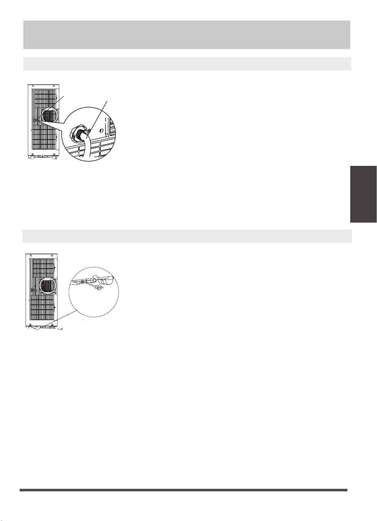
Page 19
Retirez le
bouchon de
vidange
inférieur
Lorsque le niveau d'eau du plateau inférieur atteint un niveau
prédéterminé, l'unité émet 8 bips, la zone d'achage numérique
ache "P1". À ce moment, le processus de climatisation/
déshumidication s'arrêtera immédiatement.
Cependant, le moteur du ventilateur continuera de fonctionner
(c'est normal).
Déplacez soigneusement l'unité vers un endroit de vidange, retirez
le bouchon de vidange inférieur et laissez l'eau s'écouler. Réinstallez
le bouchon de vidange inférieur et redémarrez la machine jusqu'à
ce que le symbole "P1" disparaisse.
Si l'erreur se répète, appelez le service technique.
REMARQUE: Assurez-vous de réinstaller fermement le bouchon de
vidange inférieur pour éviter les fuites avant d'utiliser l'unité.
Guide de drainage du bac de collecte d'eau
Pendant les modes de déshumidication, retirez le bouchon de
vidange à l'arrière de l'unité, installez le connecteur de vidange
(raccord femelle universel 5/8") avec un tuyau de 3/4" (acheté
localement). Pour les modèles sans connecteur de vidange, il
sut de xer le tuyau de vidange au trou. Placez l'extrémité
ouverte du tuyau directement au-dessus de la zone de vidange
de votre sol de sous-sol.
REMARQUE: Assurez-vous que le tuyau est bien xé pour éviter
les fuites. Dirigez le tuyau vers la vidange, en veillant à ce qu'il
n'y ait pas de plis qui arrêteront l'écoulement de l'eau. Placez
l'extrémité du tuyau dans la vidange et assurez-vous que
l'extrémité du tuyau est vers le bas pour laisser l'eau s'écouler en
douceur. Lorsque le tuyau de vidange continu n'est pas utilisé,
assurez-vous que le bouchon de vidange et le bouton sont
installés fermement pour éviter les fuites.
Étape 1 :
Retirez le
bouchon
de vidange
Guide de drainage du mode déshumidication
Étape 2 :
Installer le tuyau de
vidange continu
Guide de drainage
Guide de drainage
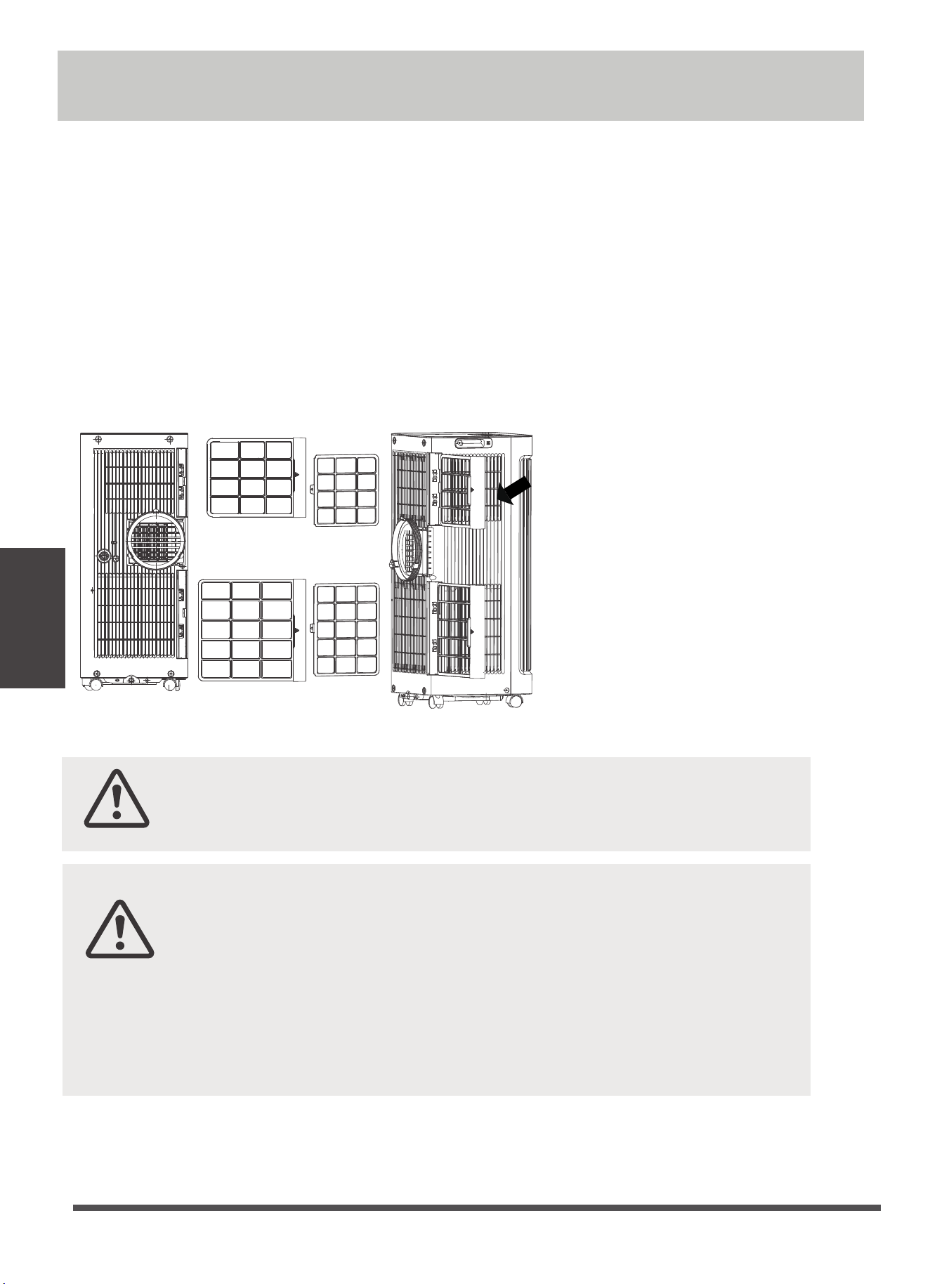
Page 20
Nettoyage et entretien
Comment nettoyer et entretenir votre climatiseur.
Nettoyage du ltre à air et du boîtier
Filtre à air
(retirer)
Retirez le ltre à air
ATTENTION :
· Toujours débrancher l'appareil avant de le nettoyer ou de le réparer.
· NE PAS utiliser de liquides inammables ou de produits chimiques pour
nettoyer l'appareil.
· NE PAS laver l'appareil sous l'eau courante. Le faire cause un danger
électrique.
· NE PAS faire fonctionner la machine si l'alimentation a été endommagée
pendant le nettoyage. Un cordon d'alimentation endommagé doit être
remplacé par un nouveau cordon du fabricant.
ATTENTION :
NE PAS faire fonctionner l'appareil sans ltre car la saleté et les peluches le
boucheront et réduiront ses performances.
Nettoyez l'appareil avec un chion humide, sans peluches et un détergent doux. Séchez l'appareil avec un
chion sec, sans peluches.
Conseils d'entretien
· Assurez-vous de nettoyer le ltre à air toutes les 2 semaines pour des performances optimales.
· Le bac de récupération d'eau doit être vidé immédiatement après l'apparition de l'erreur P1, et avant le
stockage pour éviter la formation de moisissure.
· Dans les foyers avec des animaux, vous devrez périodiquement essuyer la grille pour éviter un blocage de
l'écoulement d'air dû aux poils d'animaux.
Nettoyage et
entretien
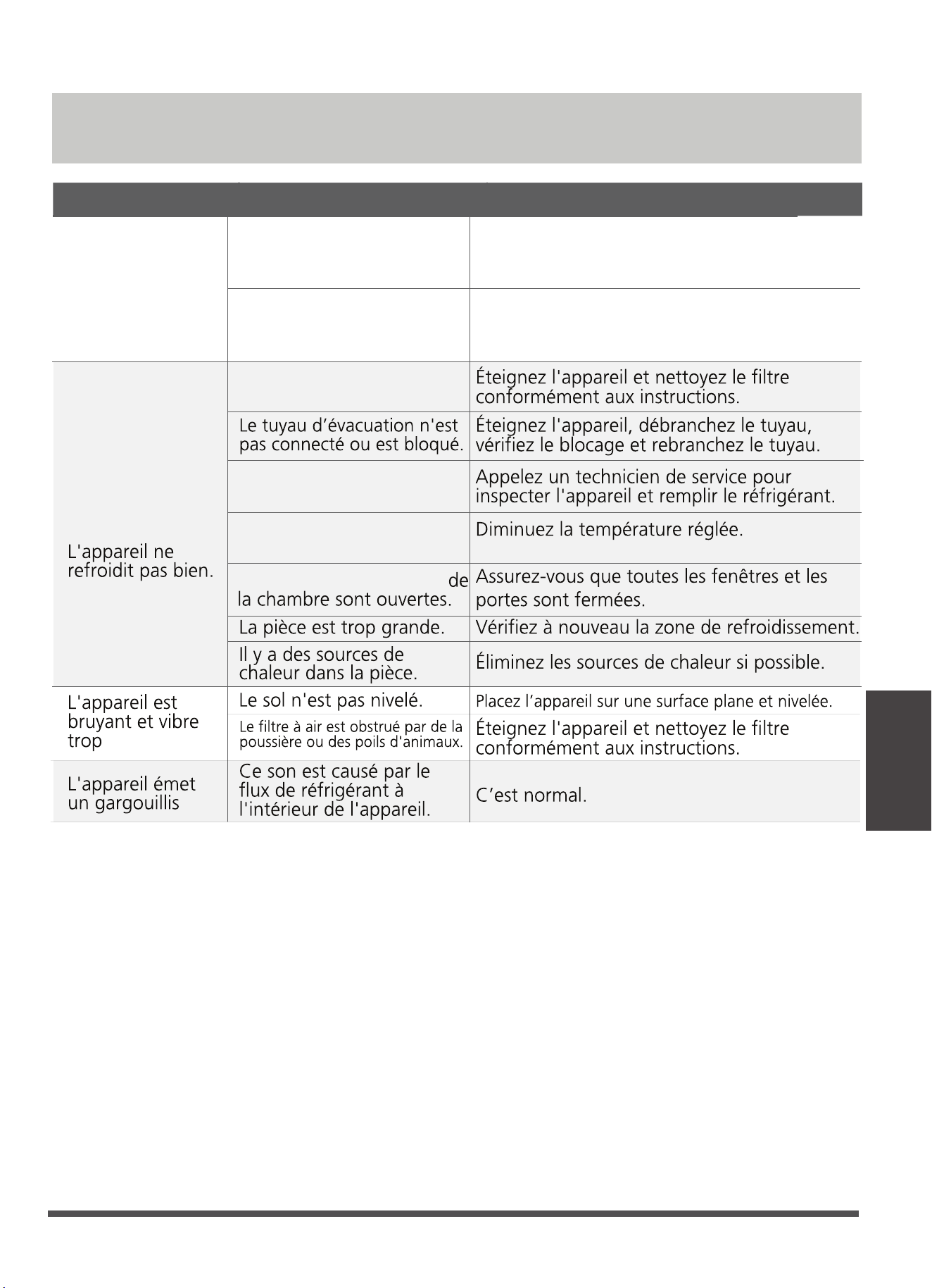
Conseils de Dépannage
Problème Causes Possibles Solution
L'appareil ne
s'allume pas
lorsque vous
appuyez sur le
bouton ON / OFF
Code d’Erreur P1
En mode REFROIDISSEMENT : la
température ambiante est
inférieure à la température dénie.
Réinitialisez la température
Le Bac Collecteur d’Eau est plein. Éteignez
l'appareil, vidangez l'eau du Bac Collecteur
d'Eau et redémarrez l'appareil.
Le ltre à air est obstrué par de
la poussière ou des poils
d'animaux.
L'appareil est faible en
réfrigérant.
Le réglage de la
température est trop élevé.
Les fenêtres et les portes
Conseils de
Dépannage
Page 21
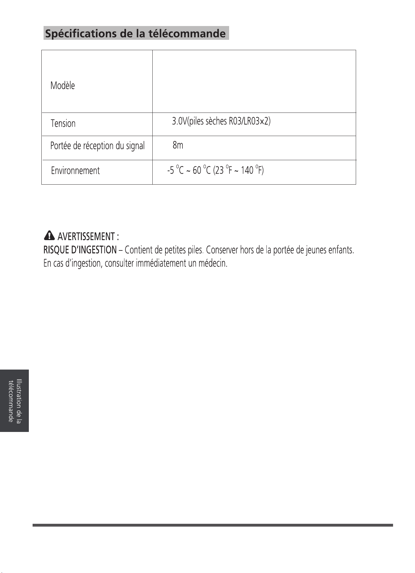
Page 22
RG57H3(B2)/BGCEF-M
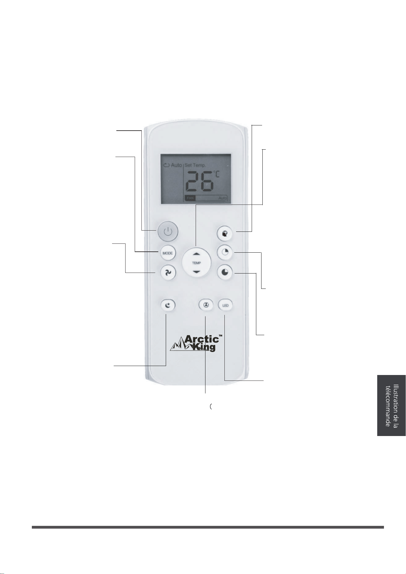
Fonctionnement des boutons
Avant d'utiliser votre nouveau climatiseur, prenez le temps de vous familiariser avec la télécommande.
Ce qui suit est une brève introduction à la télécommande. Pour les instructions d'utilisation de votre
climatiseur, veuillez vous reporter à la section Utilisation des fonctions de base du présent manuel.
SHORT CUT (raccourci)
Pour régler et activer vos
préréglages préférés.
ON/OFF (allumer/éteindre)
Pour allumer ou
éteindre l'appareil.
MODE (mode)
Pour parcourir les modes
de fonctionnement suivants :
AUTO
(automatique)
DRY
FAN SPEED
Pour sélectionner les vitesses de
ventilation dans l'ordre suivant :
AUTO LOW
SLEEP (veille)
Pour économiser
l'énergie durant les
heures de sommeil.
TEMP(température)
Pour augmenter la température
en incréments de 1 °C (1 °F).
Température maximale :
30 °C (86 °F).
Pour abaisser la température
en incréments de 1 °C (1 °F).
Température minimale :
17 °C (62 °F).
TIMER ON (minuterie activée)
Pour programmer la minuterie
pour éteindre l'appareil (se reporter
aux instructions de la section
Utilisation des fonctions de base).
TIMER OFF (minuterie désactivée)
Pour programmer la minuterie
pour éteindre l'appareil (se reporter
aux instructions de la section
Utilisation des fonctions de base).
LED (DEL)
Pour allumer ou éteindre l'écran
à DEL à l'intérieur de l'appareil.
Si vous êtes sensible à la lumière,
il vous suffit d'appuyer sur le
bouton LED (DEL) pour éteindre
l'écran à DEL de l'appareil.
Appuyer de nouveau sur le
bouton pour rallumer.
REMARQUE : Presser et maintenir
les boutons (arrow down) et (arrow
up) en même temps pendant 3
secondes pour alterner entre
l'échelle °C et °F.
COOL
(refroidissement)
FAN
HIGH
TEMP(température)
(assèchement)
(ventilation)
(automatique) (faible)
(élevé)
FOLLOW
ME(
SUIS-MOI
Bouton de détection
de température et
d'affichage de la
température
ambiante
Page 23
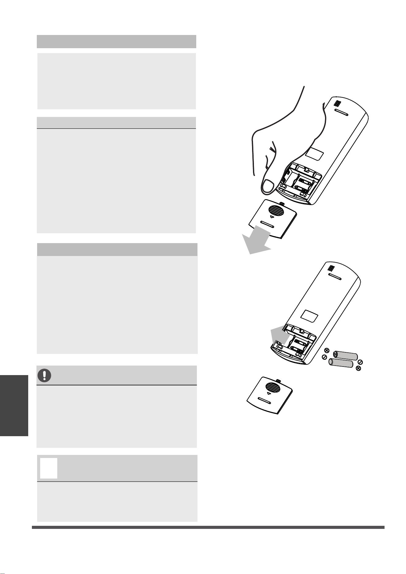
VOUS NE SAVEZ PAS À QUOI SERT UNE
FONCTION?
Consultez la description détaillée de votre
climatiseur dans les sections Utilisation des
fonctions de base et Utilisation des
fonctions avancées du présent manuel.
.
REMARQUE SPÉCIALE
Les conceptions des boutons de votre
appareil peuvent légèrement différer de
l'exemple illustré.
Si l'appareil n'est pas doté d'une fonction
précise, le bouton correspondant à cette
fonction sur la télécommande sera inactive.
En cas d'importantes différences entre la
description des fonctions dans l'illustration
de la télécommande et celle dans le
MANUEL D'UTILISATION, la description du
MANUEL D'UTILISATION prévaudra.
Insertion et remplacement des piles
Votre climatiseur comprend deux piles AAA.
Insérer les piles dans la télécommande
avant d'utiliser.
1. Glisser le couvercle arrière de la
télécommande vers le bas pour exposer le
compartiment à piles.
REMARQUES CONCERNANT LES PILES
Pour optimiser le rendement du produit :
Ne pas mélanger les piles usagées et
neuves, ou différents types de piles.
Ne pas laisser les piles dans la
télécommande si vous prévoyez ne pas
utiliser l'appareil pendant plus de 2 mois.
ÉLIMINATION DES PILES
Ne pas éliminer les piles avec les déchets
municipaux non triés. Se reporter aux lois
municipales afin d'éliminer correctement les
piles.
Fonctionnement des boutons
2. Insérer les piles en s'assurant de faire
correspondre les extrémités (+) et (-) aux
symboles à l'intérieur du compartiment à piles.
Remettre le couvercle de piles en place.
Page 24
Illustration de la
télécommande
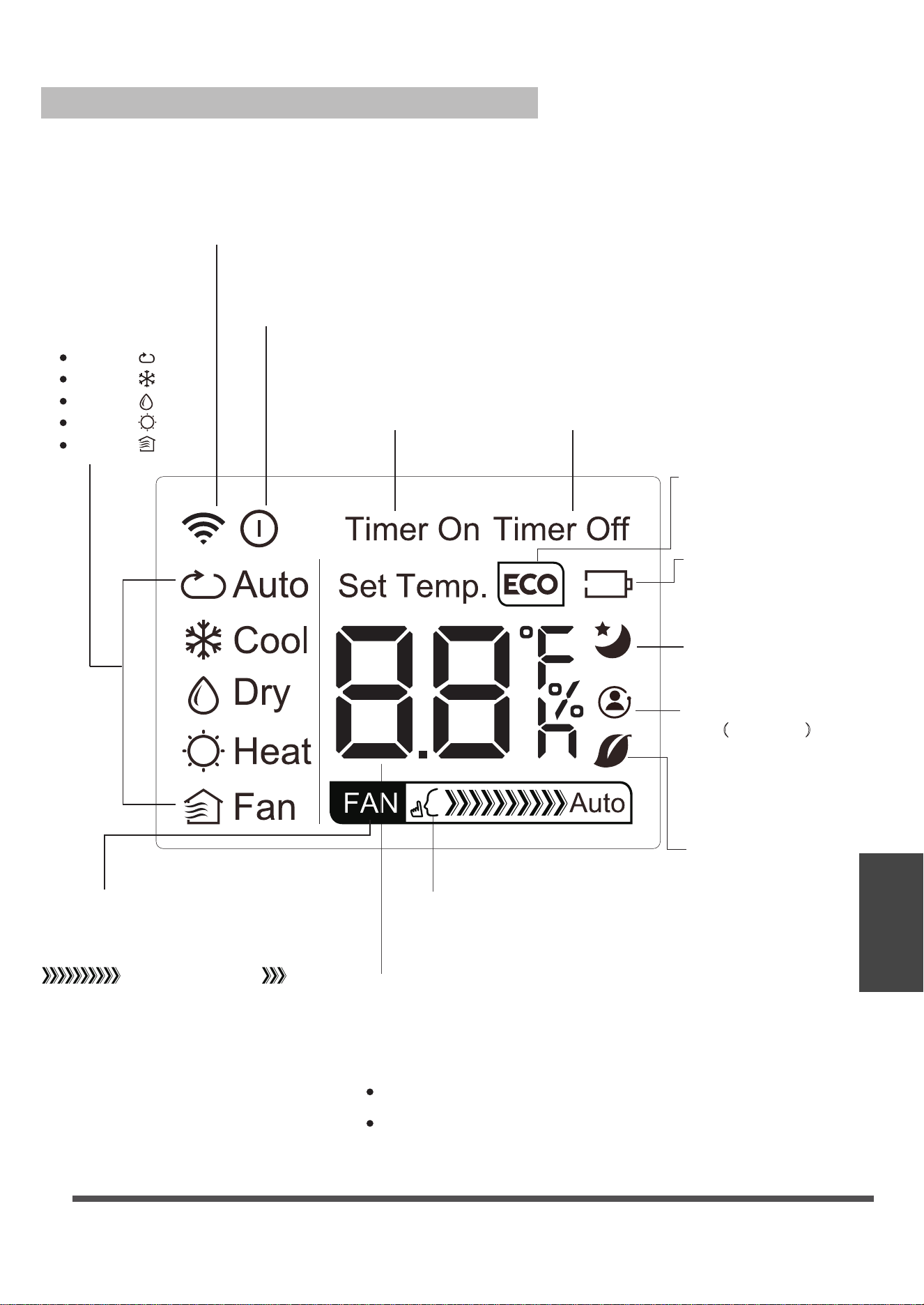
Écran MODE
Affiche le mode
actuel, y compris :
AUTO
COOL
DRY
HEAT
FAN
Témoin de transmission
S'allume lorsque la télécommande
envoie un signal à l'appareil.
Affichage ON / OFF
Apparaît lorsque l'appareil est
allumé, et disparaît quand il est éteint.
Écran TIMER ON
(minuterie activée)
S'affiche lorsque la fonction
TIMER ON (minuterie activée)
est activée.
Écran TIMER OFF
(minuterie désactivée)
S'affiche lorsque la fonction
TIMER OFF (minuterie désactivée)
est activée.
Écran VEILLE
Écran des piles
Écran SILENCIEUX
Écran ECO
S'affiche lorsque la
fonction de veille est
activée.
Écran VITESSE DE VENTILATION
Affiche la vitesse de ventilation
sélectionnée :
HIGH (élevé), ou
LOW (faible).
Cet écran est vide lorsque
la vitesse est réglée à AUTO
(automatique).
Écran TEMPÉRATURE/MINUTERIE
Affiche la température réglée par défaut ou les réglages
de la minuterie lorsque les fonctions TIMER ON/OFF
(minuterie activée/désactivée) sont utilisées :
Plage de température : 17 à 30 °C (62 à 86 °F).
Non disponible sur
cet appareil.
Non disponible sur
cet appareil.
Low battery
detection
Témoins de l'écran à DEL de la télécommande
Non disponible sur cet appareil.
Plage de réglage de la minuterie : 0 à 24 heures.
Cet écran est vide lorsque le mode FAN (ventilation) est activé.
FOLLOW
ME(
SUIS-MOI)
Bouton de détection
de température et
d'affichage de la
température
ambiante
Page 25
Illustration de la
télécommande
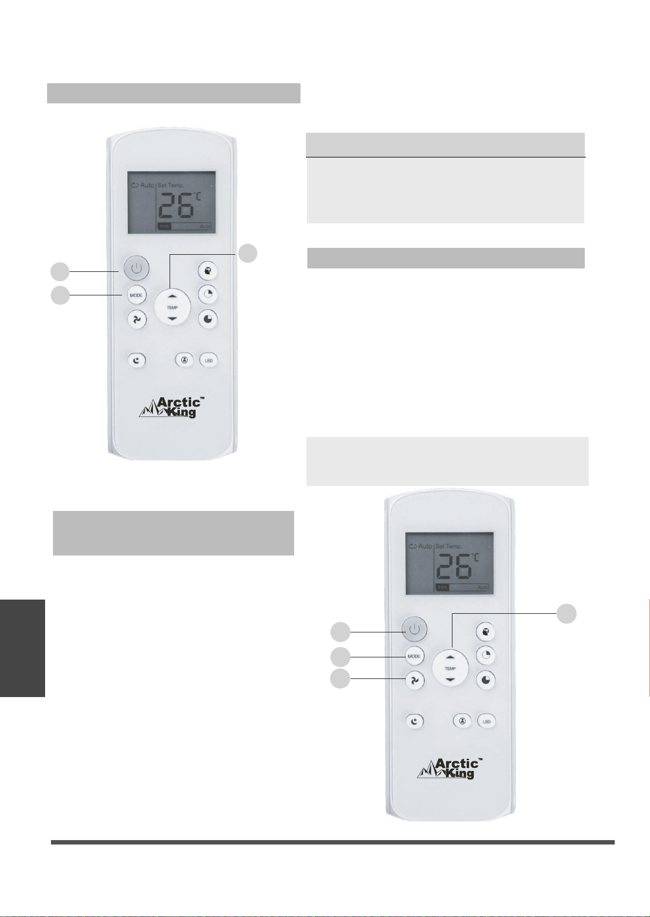
1. Appuyer sur le bouton MODE pour
sélectionner le mode COOL (refroidissement).
2. Régler à la température désirée à l'aide
du bouton Temp (arrow up) ou Temp (arrow
down).
3. Appuyer sur le bouton FAN (ventilation)
pour sélectionner la vitesse de ventilation :
AUTO (automatique), LOW (faible), MED
(moyen) ou HIGH (élevé).
4. Appuyer sur le bouton ON/OFF
(allumer/éteindre) pour démarrer l'appareil.
L'appareil en mode AUTO (automatique)
sélectionnera automatiquement le mode COOL
(refroidissement), FAN (ventilation), HEAT (chaleur)
ou DRY (assèchement), en fonction de la température
réglée.
1. Appuyer sur le bouton MODE pour sélectionner le
mode AUTO (automatique).
2. Régler à la température désirée à l'aide du bouton
Temp (arrow up) ou Temp (arrow down).
3. Appuyer sur le bouton ON/OFF (allumer/éteindre)
pour démarrer l'appareil.
REMARQUE : La VITESSE DE VENTILATION ne
peut pas être réglée en mode AUTO
(automatique).
RÉGLAGE DE LA TEMPÉRATURE
La température de fonctionnement de l'appareil
se situe entre 17 et 30 °C (62 et 86 °F). La
température réglée peut être augmentée ou
diminuée en incréments de 1 °C (1 °F).
Utilisation des fonctions de base
Fonctionnement du mode COOL
(refroidissement)
Utilisation du mode AUTO (automatique)
1
3
2
1
3
2
4
Page 26
Illustration de la
télécommande
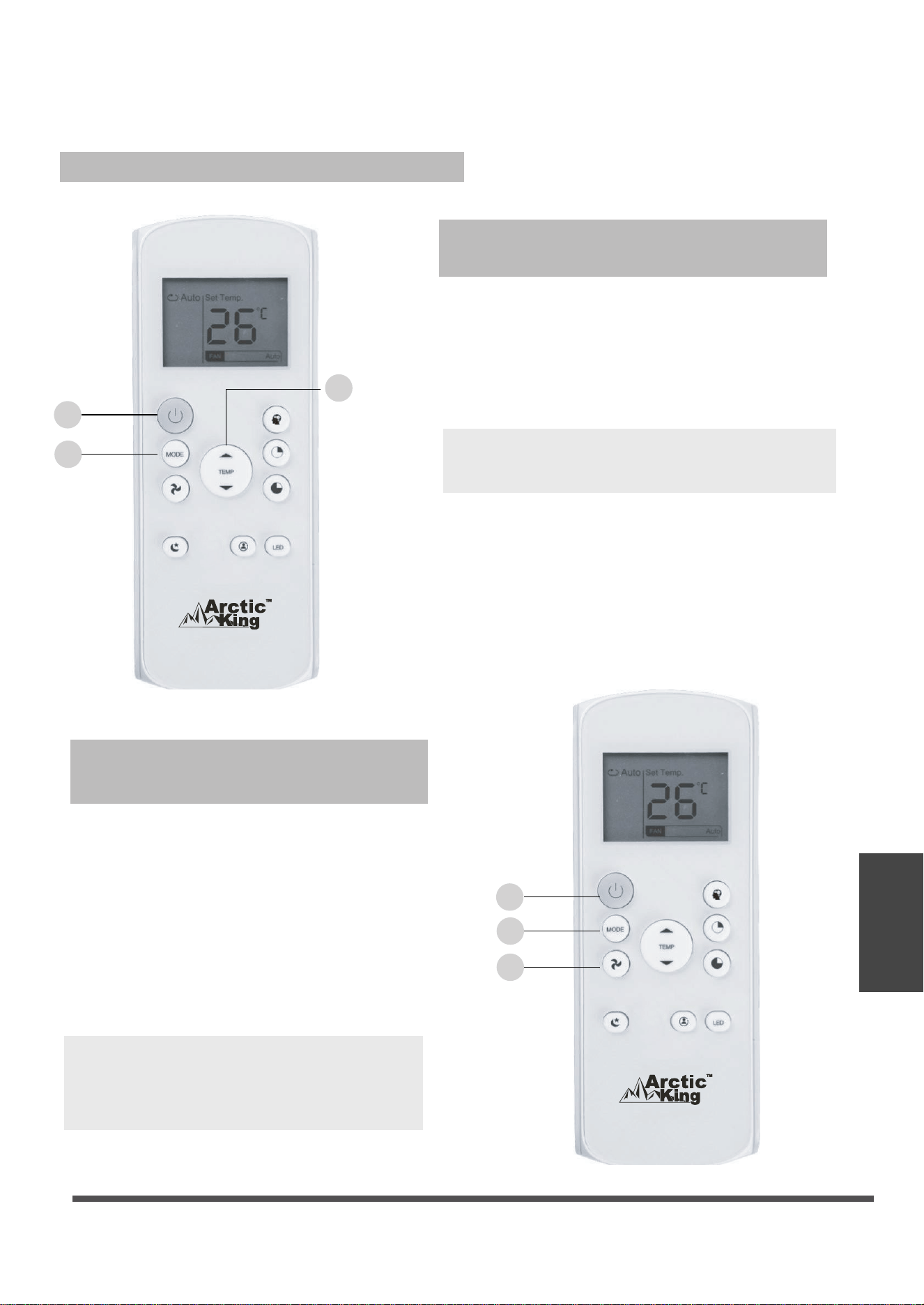
1. Appuyer sur le bouton MODE pour
sélectionner le mode DRY (assèchement).
2. Régler à la température désirée à l'aide du
bouton Temp (arrow up) ou Temp (arrow down).
3. Appuyer sur le bouton ON/OFF (allumer/éteindre)
pour démarrer l'appareil.
REMARQUE : La vitesse de ventilation ne peut
pas être modifiée en mode DRY (assèchement).
1. Appuyer sur le bouton MODE pour
sélectionner le mode FAN (ventilation).
2. Appuyer sur le bouton FAN (ventilation)
pour sélectionner la vitesse de ventilation :
AUTO (automatique), LOW (faible),
MED (moyen) ou HIGH (élevé).
ON/OFF
(allumer/éteindre) pour démarrer l'appareil.
REMARQUE : La température peut être
réglée en mode FAN
REMARQUE : La température peut être
réglée en mode FAN (ventilation).
Toutefois, l'écran à cristaux liquides
n'affichera pas la température.
Utilisation des fonctions de base
Utilisation du mode FAN
(ventilation)
Utilisation du mode DRY
(assèchement)
3. Appuyer sur le bouton
1
3
2
1
2
3
Page 27
Illustration de la
télécommande
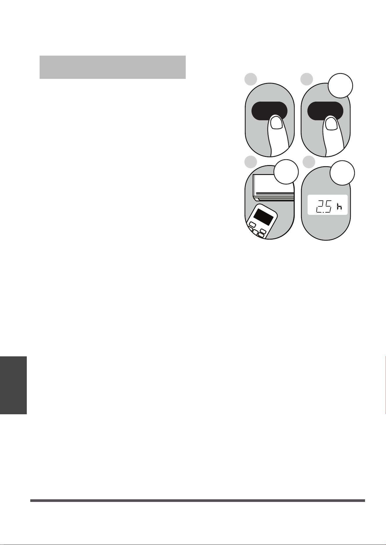
Exemple réglage pour que l'appareil
s'allume après 2,5 heures.
:
2sec
ON/OFF
MODE
F
AN
SHORT
CUT
TIMER ON
TIMER OF
F
TEMP
S
L
E
EP
1sec
x5
1
3
2
4
Fonction TIMER ON (minuterie activée)
TIMER ON TIMER ON
Réglage de la fonction TIMER
(minuterie)
Votre climatiseur a deux fonctions de
minuterie connexes :
La fonction TIMER ON (minuterie activée)
fixe la période de temps après laquelle
l'appareil s'allumera automatiquement.
La fonction TIMER OFF (minuterie désactivée)
fixe la période de temps après laquelle
l'appareil s'éteindra automatiquement.
La fonction TIMER ON (minuterie activée) vous
permet de fixer une période de temps après
laquelle l'appareil s'allumera automatiquement,
par exemple, lorsque vous rentrez du travail.
1. Appuyer sur le bouton TIMER ON (minuterie
activée). Par défaut, la dernière période de
temps que vous avez fixée et la lettre « h »
apparaîtront à l'écran.
Remarque : Le chiffre indique la période de
temps après l'heure actuelle à laquelle vous
souhaitez que l'appareil s'allume. Par exemple,
si vous réglez la minuterie TIMER ON
(minuterie activée) à 2 heures, « 2h »
apparaîtra à l'écran et l'appareil s'allumera
après 2 heures.
2. Appuyer plusieurs fois sur le bouton
TMER ON (minuterie activée) pour régler
l'heure à laquelle vous souhaitez que
l'appareil s'allume.
3. Attendre 2 secondes avant que la fonction
TIMER ON (minuterie activée) ne s'active.
L'écran numérique de votre télécommande
reviendra ensuite à l'écran de température.
Page 28
Illustration de la
télécommande
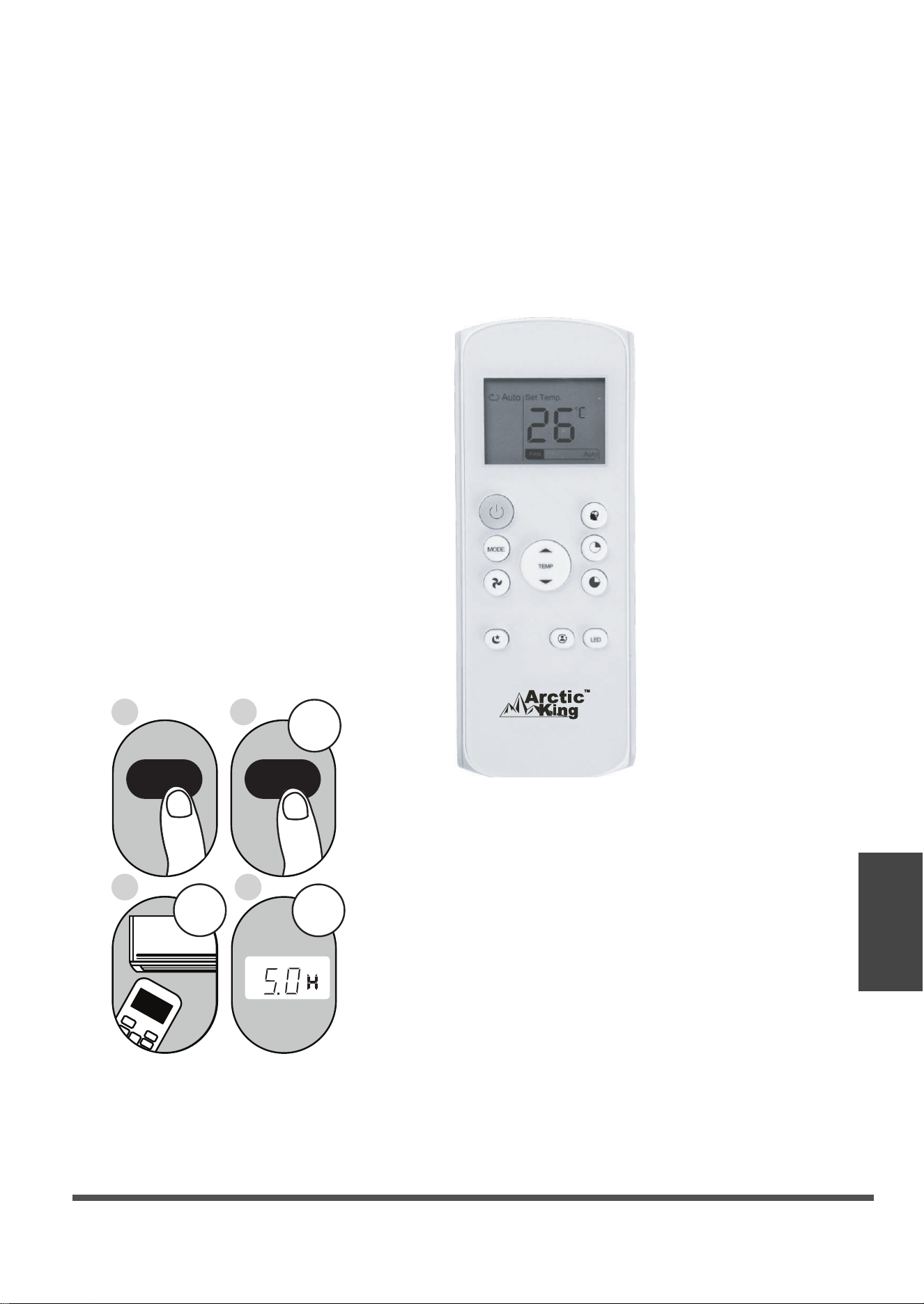
Continuer à appuyer sur
TIMER ON
(minuterie activée) ou
TIMER OFF
(minuterie désactivée)
jusqu'à la période de
temps désirée.
Fonction TIMER OFF (minuterie désactivée)
La fonction TIMER OFF (minuterie désactivée)
vous permet de de fixer une période de temps
après laquelle l'appareil s'éteindra
automatiquement, par exemple, lorsque vous
vous réveillez.
REMARQUE : Chaque pression des fonctions
TIMER ON et TIMER OFF équivaut à 30
minutes jusqu'à concurrence de 10 h. Après
10 h et jusqu'à 24 h, l'augmentation s'effectuera
par tranches de 1 h. La minuterie reviendra à
zéro après 24 h. Vous pouvez désactiver ces
fonctions en réglant la minuterie à « 0.0h ».
Exemple : réglage pour que l'appareil
s'éteigne après 5 heures.
2 sec
x10
ON/OFF
MODE
F
AN
SHORT
CUT
TIMER ON
TIMER OF
F
TEMP
S
L
EEP
1
3
2
4
TIMER OFF
FF
1 sec
TIMER OFF
1. Appuyer sur le bouton TIMER OFF (minuterie
désactivée). Par défaut, la dernière période de
temps que vous avez fixée et la lettre « h »
apparaîtront à l'écran.
Remarque : Le chiffre indique la période de
temps après l'heure actuelle à laquelle vous
souhaitez que l'appareil s'éteigne. Par exemple,
si vous réglez la minuterie TIMER OFF
(minuterie désactivée) à 2 heures, « 2h »
apparaîtra à l'écran et l'appareil s'éteindra
après 2 heures.
2. Appuyer plusieurs fois sur le bouton
TIMER OFF (minuterie désactivée) pour régler
l'heure à laquelle vous souhaitez que l'appareil
s'éteigne.
3. Attendre 2 secondes avant que la fonction
TIMER OFF (minuterie désactivée) ne s'active.
L'écran numérique de votre télécommande
reviendra ensuite à l'écran de température.
Page 29
Illustration de la
télécommande
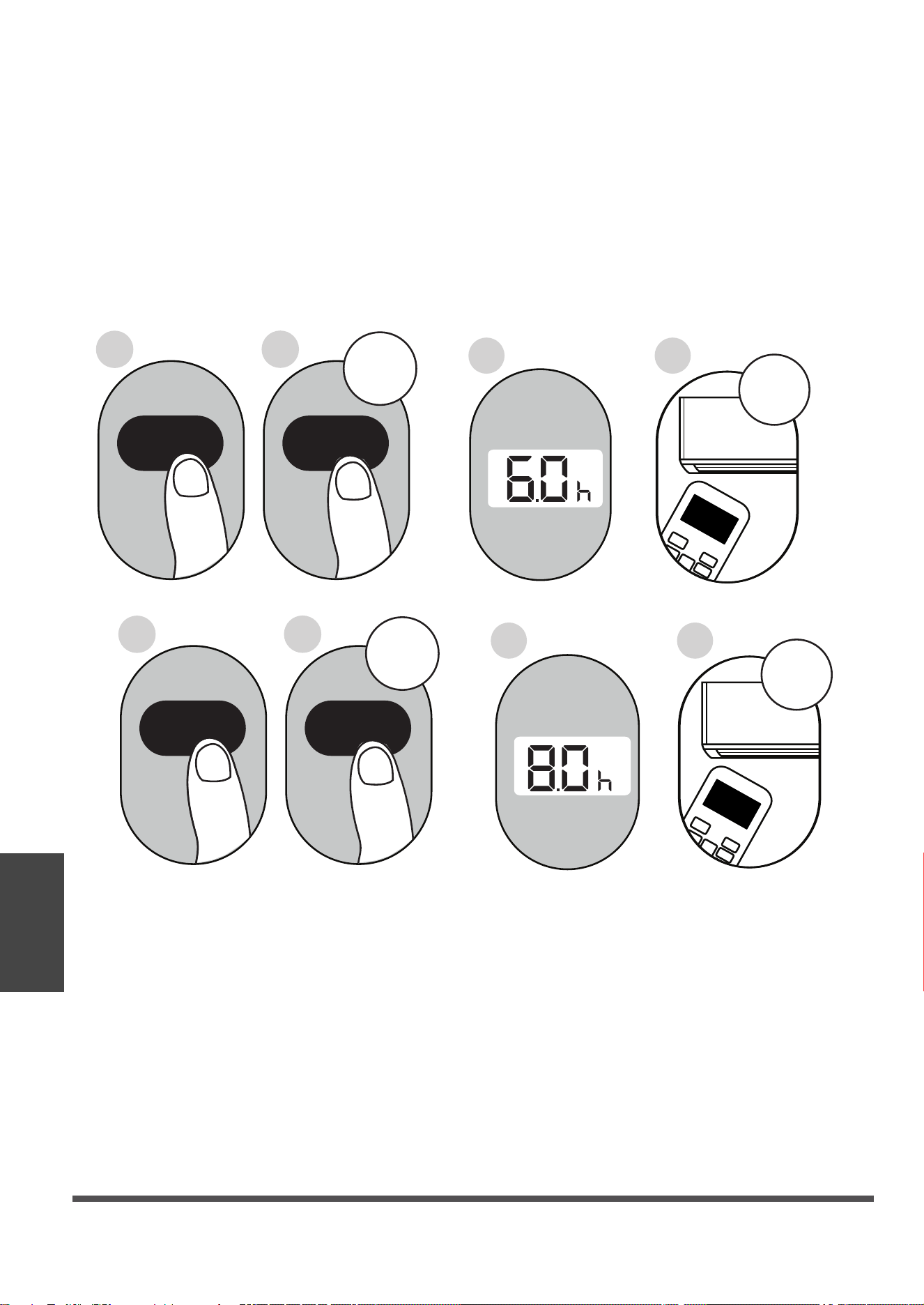
ON/OFF
ON/OFF
MODE
MODE
SHORT
SHORT
CUT
CUT
TIMER ON
TIMER ON
TEMP
TEMP
3
3
sec
sec
4
8
3
7
X12
X16
2
6
1
5
TIMER ON
TIMER ON
TIMER OFF
TIMER OFF
Réglage des fonctions TIMER ON et TIMER OFF en même temps
Prendre note que les périodes de temps que vous réglez pour les deux fonctions font référence
aux heures après l'heure actuelle. Par exemple, s'il est actuellement 13 h, et vous souhaitez
que l'appareil s'allume automatiquement à 19 h et qu'il fonctionne pendant 2 heures pour ensuite
s'éteindre à 21 h,
Procéder comme suit :
Page 30
Illustration de la
télécommande
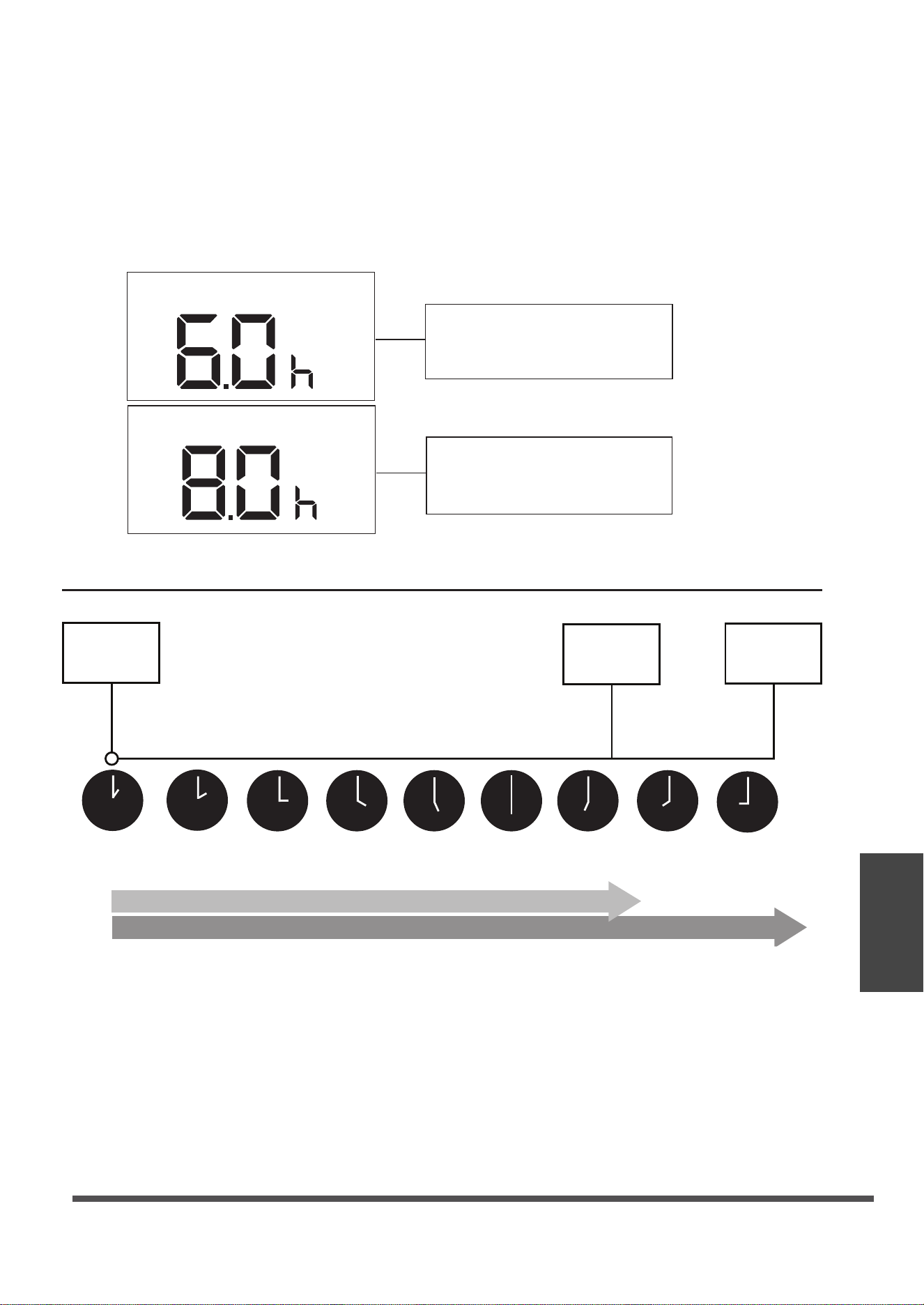
Exemple : réglage pour que l'appareil s'allume après 6 heures, fonctionne pendant 2 heures,
s'éteigne (voir la figure ci-dessous).
Écran de votre télécommande
La minuterie est réglée pour
que l'appareil s'allume 6
heures après l'heure actuelle.
La minuterie est réglée pour
que l'appareil s'éteigne 8
heures après l'heure actuelle.
Heure
actuelle 13 h
14 h 15 h
16 h 17 h
18 h 19 h 20 h 21 h
La minuterie
démarre
L'appareil
s'allumerns
L'appareil
s'éteint
6 heures plus tard
8 heures plus tard
Timer on
Timer off
c
Page 31
Illustration de la
télécommande
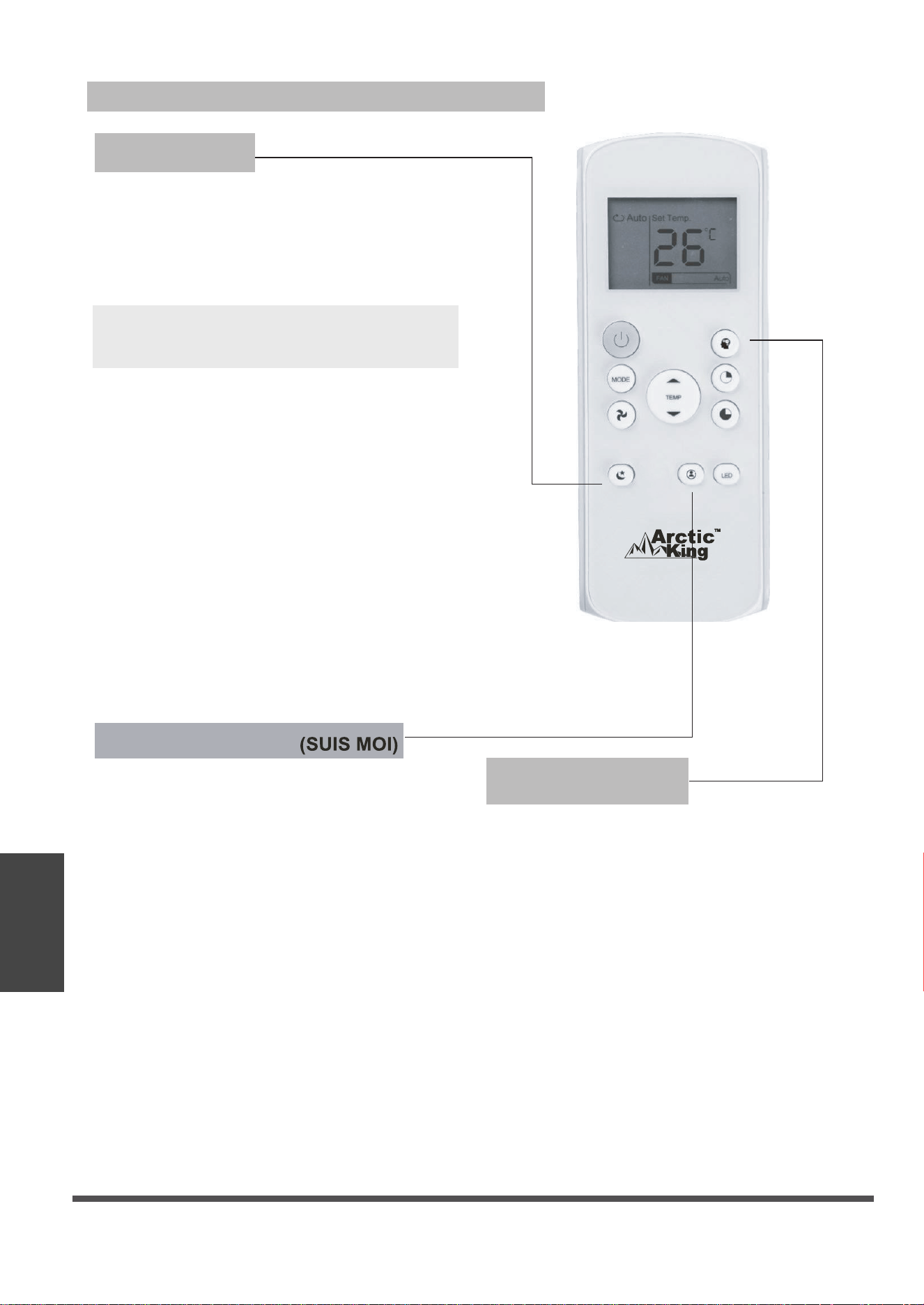
Utilisation des fonctions avancées
Fonction SHORTCUT
(raccourci)
REMARQUE : La fonction SLEEP n'est pas
disponible en mode FAN ou DRY.
Fonction SLEEP
(veille)
La fonction SLEEP permet de réduire la
consommation énergétique pendant que vous
dormez (la température n'a pas besoin d'être la
même pour être confortable). Cette fonction
s'active uniquement avec la télécommande.
● Permet de rétablir les réglages actuels
ou de revenir aux réglages précédents.
● En appuyant sur ce bouton lorsque la
télécommande est activée, le système
reviendra automatiquement aux réglages
précédents, y compris le mode de
onctionnement, la température réglée,
la vitesse de ventilation et la fonction
de veille (si activée).
● En maintenant le bouton enfoncé pendant
plus de 2 secondes, les réglages de
fonctionnement actuels seront rétablis,
y compris le mode de fonctionnement,
la température réglée, la vitesse de ventilation
et la fonction de veille (si activée).
La fonction FOLLOW ME permet à la
télécommande de mesurer la température
à son emplacement actuel. Lorsque vous
utilisez les fonctions AUTO, COOL ou
HEAT, la mesure de la température
ambiante à partir de la télécommande (au
lieu de l'unité intérieure elle-même)
permettra au climatiseur d'optimiser la
température autour de vous et d'assurer
un confort maximal.
1. Appuyez sur le bouton FOLLOW ME
pour activer la fonction. La
télécommande enverra un signal de
température à l’appareil toutes les trois
minutes.
2. Appuyez à nouveau sur le bouton
FOLLOW ME pour désactiver cette
fonction.
Fonction FOLLOW ME
Page 32
Illustration de la
télécommande

La conception des boutons repose sur le modèle habituel et peut légèrement différer
de celle de votre appareil actuel. Le cas échéant, la forme actuelle prévaudra.
Toutes les fonctions décrites sont exécutées par l'appareil. Si votre appareil n'est pas
doté d'une fonction précise, le bouton correspondant à cette fonction sur la
télécommande sera inactive.
En cas d'importantes différences entre la description des fonctions dans l'illustration
de la télécommande et celle dans le MANUEL D'UTILISATION, la description du
MANUEL D'UTILISATION prévaudra.
L'appareil pourrait être conforme aux règlements locaux ou nationaux. Au Canada,
celui-ci devrait être conforme à CAN ICES 3 (B)/NMB 3 (B). Aux États-Unis, l'appareil
est conforme à la section 15 des règlements de la FCC. Le fonctionnement est soumis
aux deux conditions suivantes : (1) L'appareil ne doit pas provoquer des interférences
nuisibles et (2) l'appareil doit accepter toute interférence reçue, y compris des
interférences pouvant entraîner un fonctionnement indésirable.
Le présent appareil a fait l'objet d'essais et répond aux restrictions des appareils
numériques de classe B, en vertu de la section 15 du règlement de la FCC. Ces
restrictions visent à fournir une protection raisonnable contre les interférences nuisibles
dans une installation résidentielle. Le présent appareil produit, utilise et peut émettre de
l'énergie radio électrique et, s'il n'est pas installé et utilisé conformément aux instructions,
peut causer des interférences nuisibles aux communications radio. Cependant, rien ne
permet de garantir que ces interférences se produiront à un moment quelconque. En
cas d'interférences avec la réception radio ou télévisuelle, qui peuvent être détectées
en allumant et en éteignant l'appareil, l'utilisateur est invité à corriger ce problème en
prenant une ou plusieurs des mesures suivantes :
-
-
-
-
-
REMARQUE :
● Réorienter ou déplacer l'antenne de réception.
● Éloigner l'appareil du récepteur.
● Brancher l’appareil à une prise autre que celle du circuit auquel le récepteur est relié.
● S’adresser au revendeur ou à un technicien radio/TV expérimenté pour obtenir de l’aide.
Toute transformation ou modification non autorisée par la partie responsable de la
conformité pourrait annuler le droit de l'utilisateur d'utiliser l'appareil.
Page 33
Illustration de la
télécommande

GARANTIE LIMITÉE POUR CLIMATISEUR
Ces produits ont été conçus pour répondre à des normes de qualité et sont garantis pour
usage domestique contre tout défaut de fabrication.
Garantie d'un (1) pièces seulement an à partir de la date d'achat; garantie limitée sur le
système scellé de la 2e à la 5e année, pour une utilisation domestique normale de
l'appareil. Cette garantie n’a aucune incidence sur vos droits légaux.
En cas de mauvais fonctionnement de votre produit (bris, pièces manquantes, etc.),
veuillez appeler notre ligne de service pour parler à un technicien au 1-888-365-2230, du
lundi au vendredi de 8 h à 18 h HNE, le samedi de 8 h à 16 h HNE. Midea se réserve le
droit de réparer ou remplacer le produit défectueux à sa discrétion.
Toute garantie est invalide si le produit a été utilisé en surcharge ou de façon non
recommandée, ou a fait l’objet de négligence ou de réparations
non effectuées par un agent autorisé. L’usage professionnel/commercial au quotidien et
l’usage intensif ne sont pas garantis. Dû à l’amélioration continue de nos produits, nous
nous réservons le droit de modifier les caractéristiques de ce produit sans
avertissement.
Pour obtenir des instructions sur la façon de drainer correctement le fréon, veuillez
contacter notre service à la clientèle au 1-888-365-2230. Je vous remercie.
Page 34