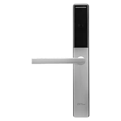

Installation Guide
Model: ZL600
Version: 1.0
English
Lock Body: European Standard Mortise Lock Case
Due to regular upgrades of systems and products, ZKTeco could not guarantee exact consistency between
the actual product and the written information in this manual.

Cautions
1.
2.
3.
Table of Contents
4.
5.
6.
7.
8.
9.
A new lock is defined as always in open mode until it is locked once by a IC S50/S70 card.
Please register an authorized card, a time sync card, and a room card initially for the
new lock.
The lock is equipped with keys for manual unlocking. Remove the keys from the
package and keep them in a safe place.
To power on the lock, four alkaline AAA batteries (not included) are required. Non-
alkaline and rechargeable batteries ARE NOT RECOMMENDED.
Do not remove the batteries when the lock is in working state.
When the battery power is low, the lock will beep to remind the user to replace the
batteries. Make sure not to mix up the polarities while replacing the batteries.
Avoid contact with corrosive substances. Do not hang any object on the handle.
The built-in software manages the operation of access cards. Please refer the
software user manual.
For further queries, please contact the seller.
1
What's in Box...................................................................................................................2
Installation Diagram.......................................................................................................3
Installation Procedure....................................................................................................3
1. Door Opening Direction...........................................................................................................................3
2. Drilling Holes on the Door.......................................................................................................................5
3. Installation of Mortise..............................................................................................................................6
4. Installation of Outdoor Unit...................................................................................................................7
5. Installation Indoor Unit............................................................................................................................8
6. Install Batteries............................................................................................................................................8
7. Installation of Strike Plate and Box.......................................................................................................9
8. Test the Lock by Mechanical Key.......................................................................................................10
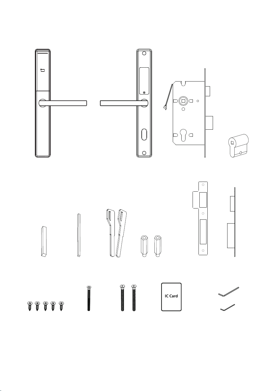
What's in Box
Note: This lock is ideal for doors with a thickness of 32 mm to 58 mm. This lock will not fit on a
door that is thicker than 58 mm. Please contact the salesperson if you have any queries.
Outdoor Unit Indoor Unit Mortise Cylinder
Spindle A Spindle B Keys Studs Strike Plate and Box
Screw A Screw B Screw C IC Card
Hex Wrench A
Hex Wrench B
2
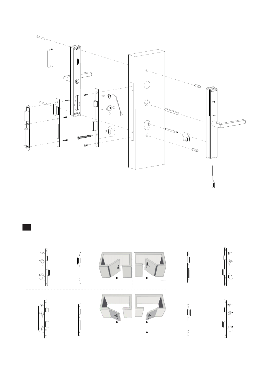
Installation Diagram
3
Installation Procedure
Screw C
Battery Cover
Screw C
Box
Strike Plate
Indoor Unit
Screw B
Screw A
Screw A
Mortise
Spindle A
Stud
Spindle B
Keys
Cylinder
Outdoor Unit
Stud
1
Door Opening Direction
3085 Mortise
Left Inward
Right Inward
Left Outward
Right Outward
Mortise Strike Plate Strike Plate Mortise
Mortise Strike Plate Strike Plate Mortise
Person Location
6085 Mortise
Person Location
Mortise Strike Plate Strike Plate Mortise
Mortise Strike Plate Strike Plate Mortise
Left Inward
Right Inward
Left Outward
Right Outward
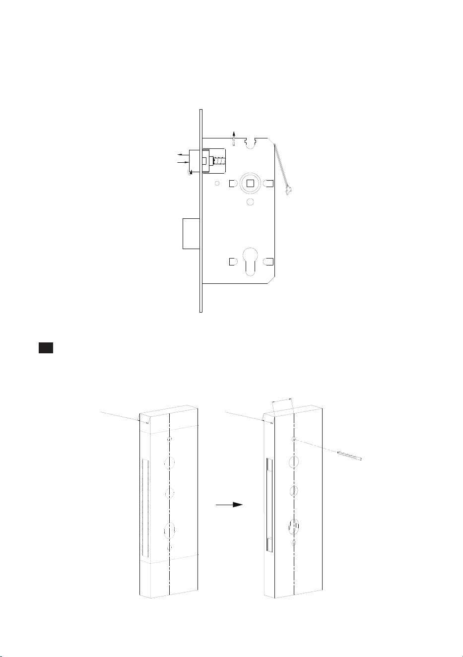
Note: Please install the Mortise and Strike Plate according to the above illustration.
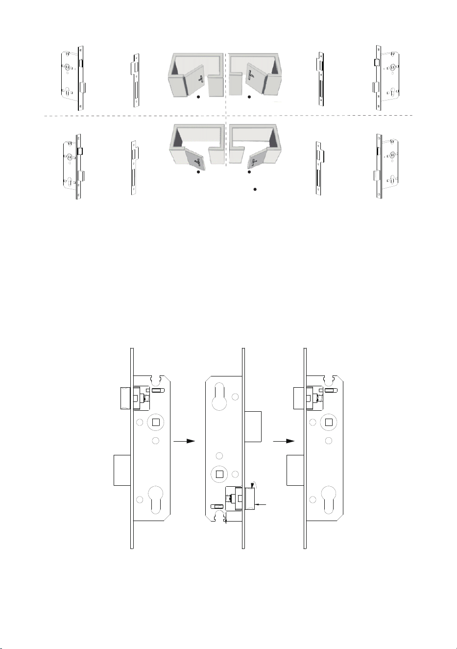
v Adjustment of 3085 Mortise
Adjust the Latch's Direction (if necessary)
When you rotate the mortise 180 degrees, the fastener will dropdown.
Insert the latch into the mortise.
Disentangle the latch by turning it to 180 degrees.
Rotate the mortise to 180 degrees again.
1)
2)
3)
4)
1
2
3
4
4
v Adjustment of 6085 Mortise
Push Up the fastener.
The latch pops up.
Rotate the latch 180 degrees.
Push the latch back.
1)
2)
3)
4)
1
2
4
3
2
Drilling Holes on the Door
Paste the Installation Template at the desired handle height.
Mark for the holes to be drilled and drill the marked places.
1)
2)
Do
o
r
Th
i
ckne
s
s:
3
2 to 5
8mm
Do
or Th
i
c
k
n
es
s
:
3
2 to 58
mm
3
0
/6
0
mm
Installation Template
5
3
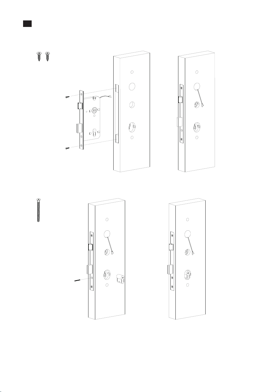
Installation the Mortise
Insert the Cylinder, then secure it with Screw B.
Insert the mortise into the drilled hole, secure it with Screw A, and make sure the
cable is towards the outdoor unit.
1)
2)
Screw A
Screw B
6
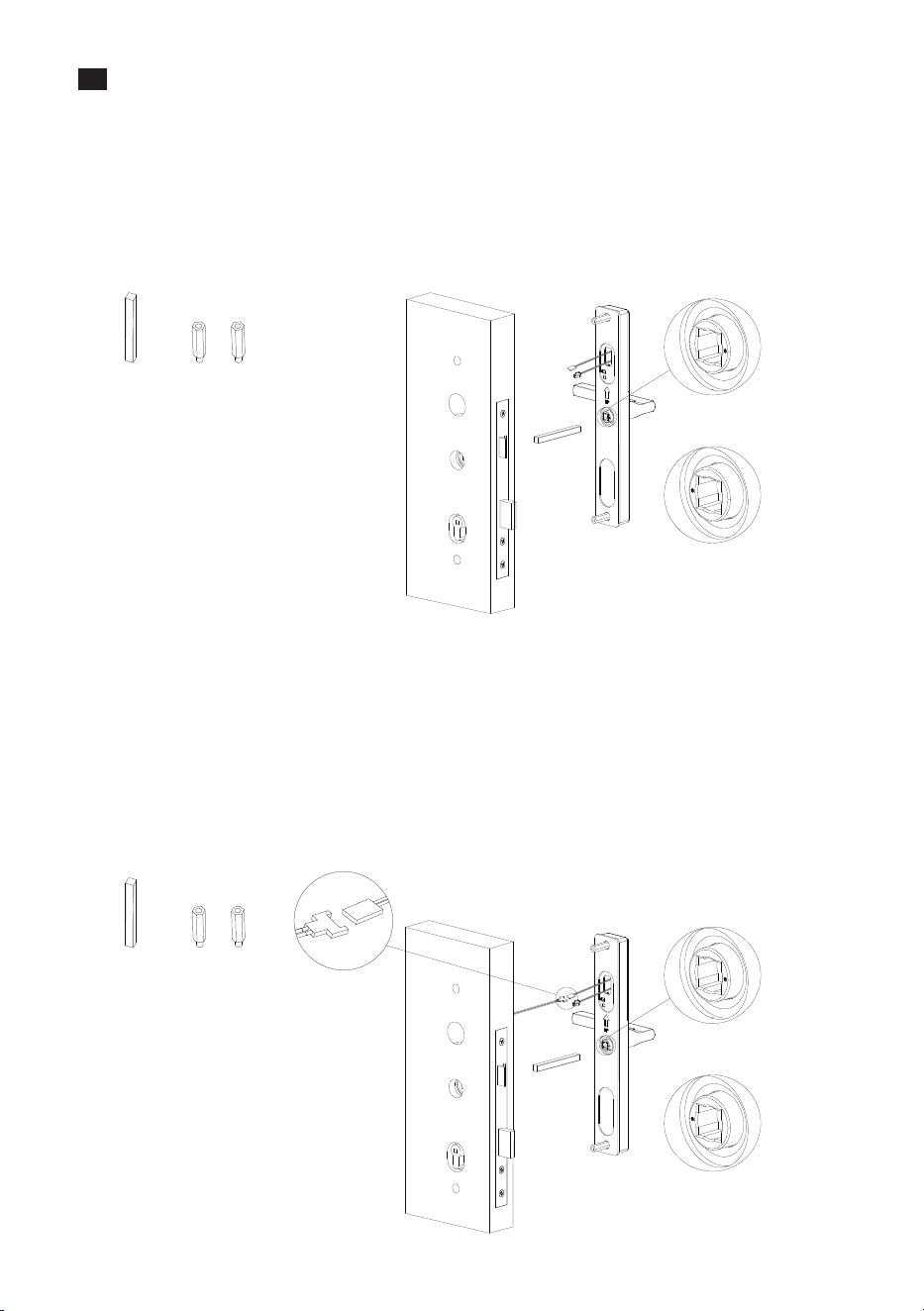
Insert a Spindle A into the clutch toward Outdoor Unit.
Attach the Outdoor Unit to the door by connecting the 2 PIN cable of 6085
Mortise with mainboard.
2)
3)
Note: Please pay attention to the point of clutch, the point is at right side when right
opening, the point is at left side when left opening.
4
Installation the Outdoor Unit
v Method of 3085 Mortise
Install the Studs on the back of the Outdoor Unit.
Insert a Spindle A into the clutch toward Outdoor Unit.
Attach the Outdoor Unit to the door.
1)
2)
3)
Spindle A
Note: Please pay attention to the point of clutch, the point is at right side when right
opening, the point is at left side when left opening.
Right Opening
Left Opening
v Method of 6085 Mortise
Install the Studs on the back of the Outdoor Unit.
1)
Studs
7
Spindle A
Right Opening
Left Opening
Studs
8
5
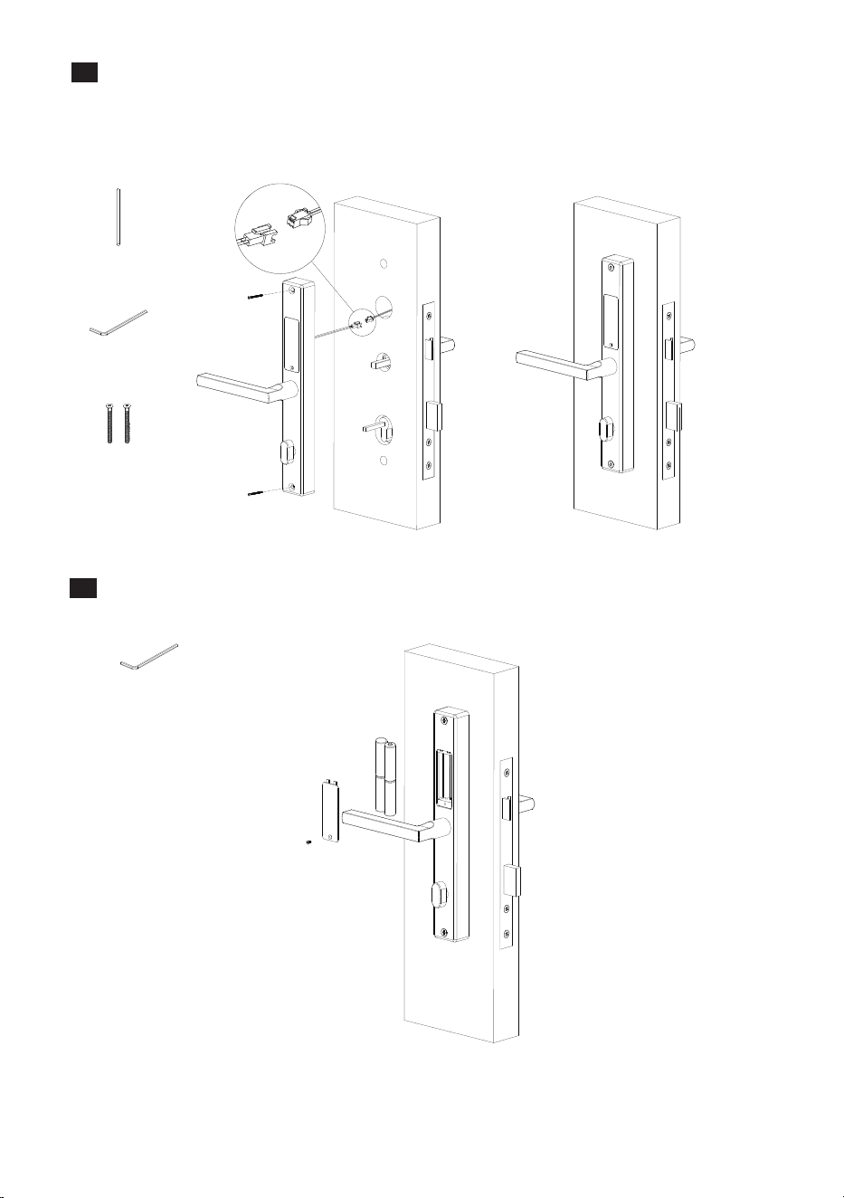
Installation Indoor Unit
Insert the Spindle B into the cylinder and turn it to 45°.
Connect the battery cable with the mainboard.
Secure the Indoor Unit with 2 Screws C by Hex Wrench A.
1)
2)
3)
Spindle B
Hex Wrench A
Screw C
6
Install Batteries
To install batteries, remove the Battery Cover with Hex Wrench B, then reinstall it.
Hex Wrench B
9
7
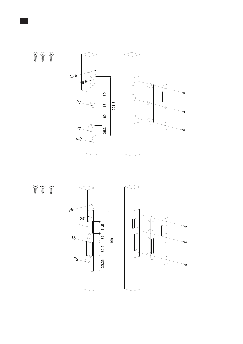
Installation of Strike Plate and Box
Make sure that the Strike Box is aligned with the latch bolt. Then, use the Installation
Template to drill holes.
Align the Strike Plate and Box with the drilled holes and secure them with Screw A.
1)
2)
Screw A
3085 Mortise
Unit: mm
6085 Mortise
Screw A
Unit: mm
8
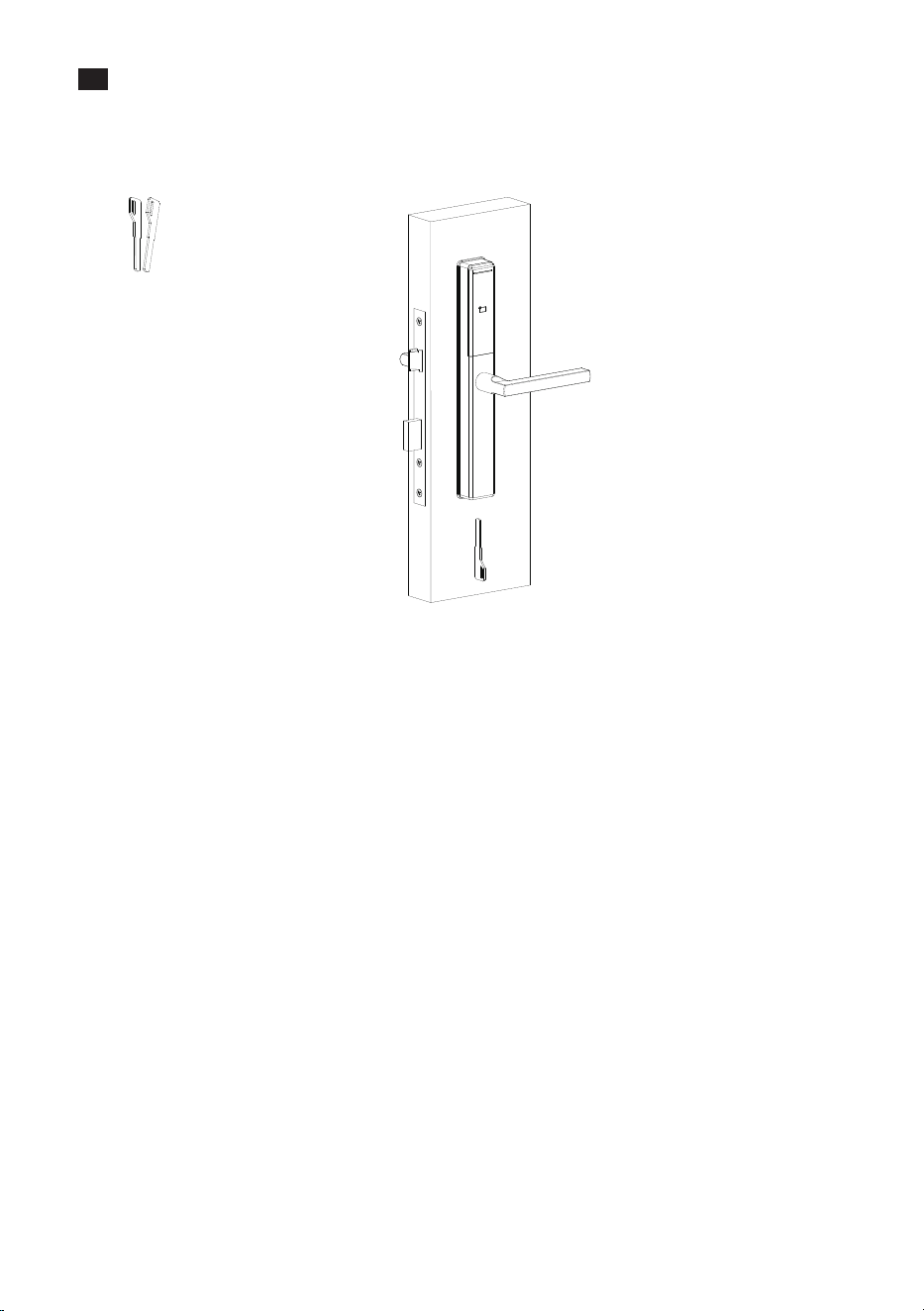
Test the Lock by Mechanical Key
Insert one of the key and rotate it to 90° and then press the outdoor unit handle, if the
latch backs up, it means exact.
Note: The handle of outdoor unit is always free.
Keys
10

This device complies with Part 15 of the FCC Rules. Operation is subject to the following two
conditions: (1) This device may not cause harmful interference, and (2) this device must accept
any interference received, including interference that may cause undesired operation.
This equipment has been tested and found to comply with the limits for a Class B digital device,
pursuant to Part 15 of the FCC Rules. These limits are designed to provide reasonable protection
against harmful interference in a residential installation. This equipment generates, uses, and
can radiate radio frequency energy and, if not installed and used in accordance with the
instructions, may cause harmful interference to radio communications. However, there is no
guarantee that interference will not occur in a particular installation. If this equipment does
cause harmful interference to radio or television reception, which can be determined by
turning the equipment off and on, the user is encouraged to try to correct the interference by
one or more of the following measures:
Warning:
Connect the equipment into an outlet on a circuit different from that to which the
receiver is connected.
IMPORTANT! Any changes or modifications not expressly approved by the party responsible
for compliance could void the user's authority to operate the equipment.
Reorient or relocate the receiving antenna.
Increase the separation between the equipment and receiver.
Consult the dealer or an experienced radio/TV technician for help.
FCC RF Radiation Exposure Statement:
This Transmitter must not be co-located or operating in conjunction with any other
antenna or transmitter.
This equipment complies with RF radiation exposure limits set forth for an uncontrolled
environment.
11

ZKTeco Industrial Park, No. 32, Industrial Road,
Tangxia Town, Dongguan, China.
Phone : +86 769 - 82109991
Fax : +86 755 - 89602394
www.zkteco.com
Copyright © 2023 ZKTECO CO., LTD. All Rights Reserved.


