1
Installation Guide
AT-JUNO-451
4K HDR Four-Input HDMI Switcher with Auto-Switching and
Return Optical Audio
AT-JUNO-451
1 x AT-JUNO-451
1 x 4-pin captive screw connector
2 x Mounting plates
4 x Rubber feet
4 x Screws
1 x DC 5V power supply
1 x IEC cord
Package Contents
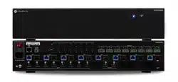
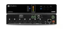
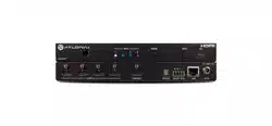
The Atlona JunoX™ 451 (AT-JUNO-451) is a 4×1 HDMI switcher for high dynamic range (HDR)
formats. Part of the comprehensive family of Atlona 4K HDR integration products, it is HDCP 2.2
compliant and supports 4K/UHD video @ 60 Hz with 4:4:4 chroma sampling, as well as HDMI
data rates up to 18 Gbps. The JunoX 451 is ideal for residential applications with the latest as
well as emerging 4K/UHD and HDR sources and displays. It includes EDID management features
and automatic input switching. The JunoX 451 also supports the HDMI Audio Return Channel
(ARC) for receiving digital audio from a television. A TOSLINK digital audio output is provided
for sending ARC or de-embedded HDMI audio to an AV receiver or soundbar. This JunoX Series
HDMI switcher can be controlled via Ethernet, RS-232, and IR.
IMPORTANT: Visit https://www.atlona.com/product/AT-JUNO-451 for the
latest rmware updates and User Manual.
NOTE: The AT-JUNO-451 no longer ships with an IR remote control.
However, IR documentation remains for units currently in the eld.
2
Installation Guide
AT-JUNO-451
POWER
JUNOX
1 2 3 4
INPUT INPUT FW
TM
1 2 3 4
HDMI IN
HDMI OUT
OPTICAL
AT-JUNO-451
RS-232 IR IN LAN
DC 5V
TX
S
RX
POWER
JUNOX
1 2 3 4
INPUT INPUT FW
TM
1 2 3 4
HDMI IN
HDMI OUT
OPTICAL
AT-JUNO-451
RS-232 IR IN LAN
DC 5V
TX
S
RX
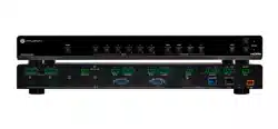
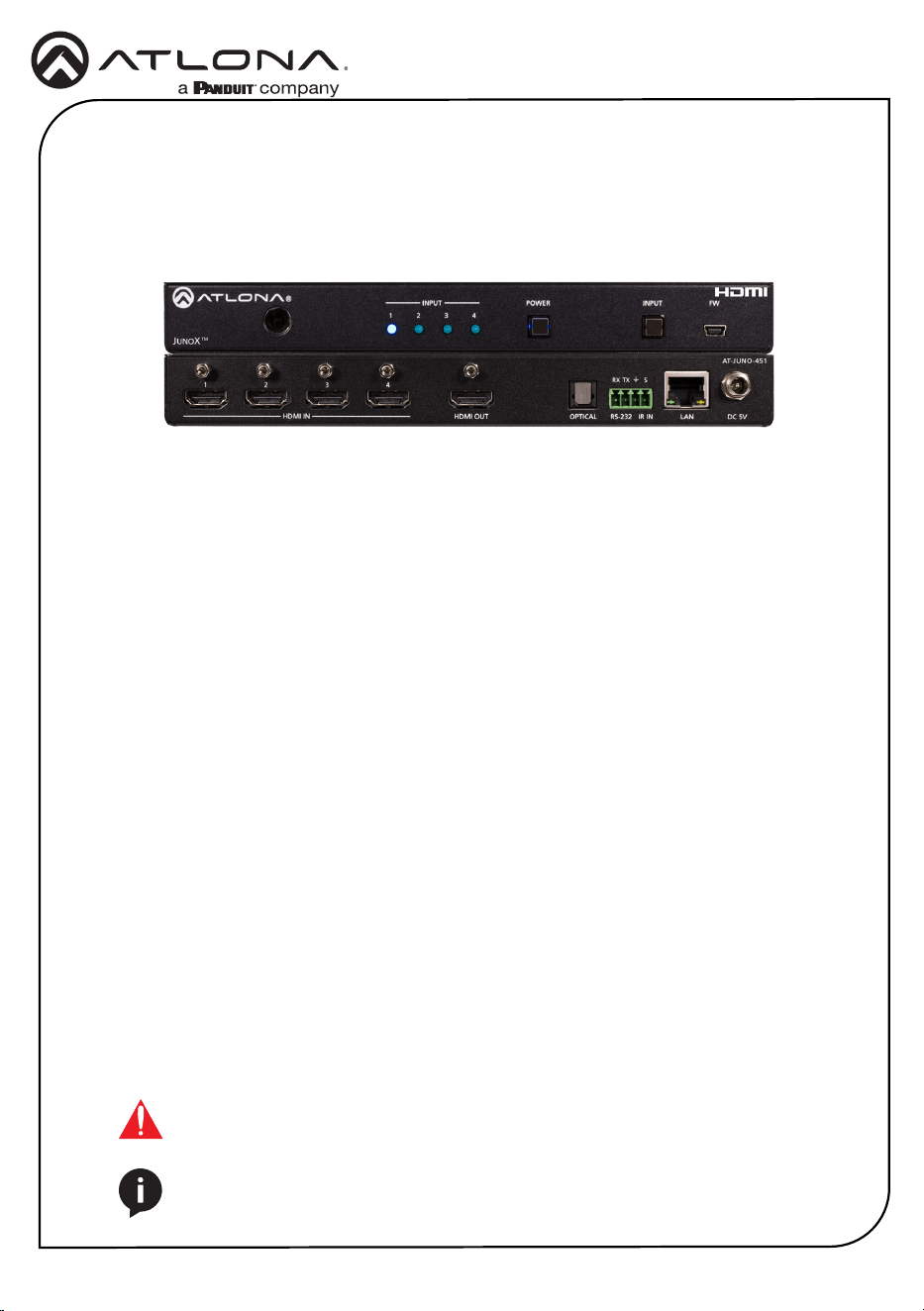
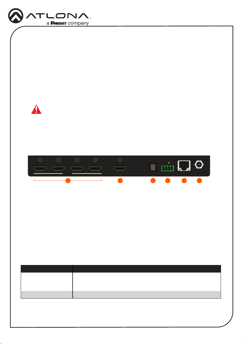
1 IR Window
Receives IR signals from the IR remote.
2 Input Indicators
These LED indicators glow solid blue to
indicate the active input.
3 POWER
Press this button to power-on or power-
o the unit.
4 INPUT
Press and release this button to cycle
through each of the inputs.
5 FW
Connect a mini USB cable to this port to
update the rmware.
6 HDMI Inputs
Connect an HD/UHD source to each of
these HDMI ports.
7 HDMI OUT
Connect an HDMI cable from this port to
a display or other sink device. This output
supports multichannel audio.
8 OPTICAL
Connect an optical audio cable from this
TOSLINK port to an audio output device.
This port can be used as part of the Audio
Return Channel (ARC). Refer to the User
Manual for more information.
9 RS-232 / IR IN
Connect the included 4-pin captive
screw block to this port. Refer to RS-232
/ IR Connector (page 3) for wiring
information.
10 LAN
Connect an Ethernet cable from this port
to a Local Area Network (LAN). This port
only supports direct control of the unit.
11 DC 5V
Connect the included 5 V DC power
supply to this power receptacle.
Panel Descriptions
1 2
6
3
7
4
8 9 10
5
11
3
Installation Guide
AT-JUNO-451
RS-232 / IR Connector
The AT-JUNO-451 provide RS-232 and IR control, using the included four-pin captive screw
connector. Electrical IR or RS-232 signals, from a control system, can be used for control.
Atlona recommends the AT-LC-CS-IR-2M (sold separately) for easy connection to the captive
screw connector.
1. Use wire strippers to remove a portion of the cable jacket.
2. Remove at least 3/16” (5 mm) from the insulation of each wire.
3. Insert the wires into the correct terminal on the included captive screw connector, as shown
below.
4. Tighten the screws to secure the wires. Do not use high-torque devices as this may
damage the screws and/or connector.
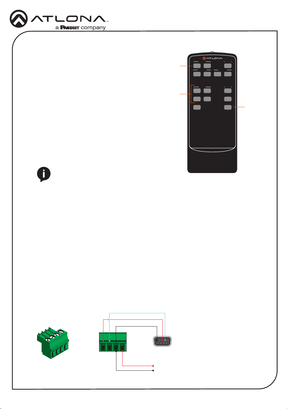
The IR remote control that can be used to operate
the unit from a remote location.
GND
to control system
or AT-VCC-IR-KIT
RX
TX
S
GND
IR Remote Control
SW-R1
Video 1
Video
Video 2
All On
Power
Vol +
Vol
-
Mute
1
3
2
4
5
Input
Audio
On
Off
On
Off
On
Off
1 On / O buttons
Press the On button to power-on the unit.
Press the O button to power-o the unit.
2 Input
Press these buttons (1 - 4) to select the desired
input.
3 Mute
Press this button to toggle audio muting on the
HDMI OUT port. The Output 1 toggle switch,
in the web GUI, will also change to reect the
current muting state. Refer to the User Manual
for more information.
1
3
2
NOTE: The AT-JUNO-451 no longer ships with
an IR remote control. However, IR documentation
remains for units currently in the eld.
4
Installation Guide
AT-JUNO-451
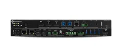
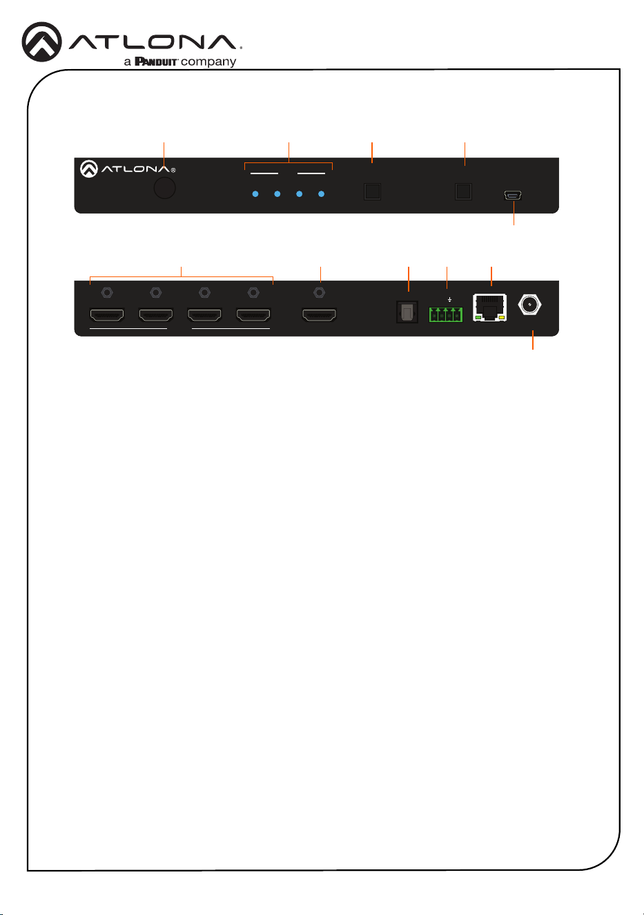
1. Connect a source to each of the four HDMI inputs (INPUT 1 - INPUT 4).
2. Connect a display to the HDMI OUT port.
3. Connect an optical audio cable from the OPTICAL port to a sound bar or other audio output
device. Audio Return Channel (ARC) is supported. Refer to the User Manual for more
information.
4. Connect the included 4-pin captive screw block to the RS-232 / IR IN port.
Refer to RS-232 / IR Connector (page 3) for wiring information.
5. Connect an Ethernet cable from the LAN port to the Local Area Network (LAN).
Installation
IMPORTANT: Stranded or patch cables are not recommended due to
performance issues.
6. Connect the included 5 V DC power supply to the DC 5V power receptacle.
7. Connect the power supply to an available electrical outlet.
POWER
JUNOX
1 2 3 4
INPUT INPUT FW
TM
1 2 3 4
HDMI IN
HDMI OUT
OPTICAL
AT-JUNO-451
RS-232 IR IN LAN
DC 5V
TX
S
RX
1 2 3 4 5 6
IP Conguration
By default, the AT-JUNO-451 is set to DHCP mode, allowing a DHCP server (if present) to assign
the unit an IP address.
1. Make sure the unit is powered.
2. Press and hold the INPUT button for approximately 10 seconds.
3. Release the button once the POWER button begin to ash. The number of ashes will
indicate the currently selected IP mode:
POWER button ashes Description
Two Static IP mode IP address: 192.168.1.254
Subnet mask: 255.255.0.0
Gateway: 192.168.1.1
Four DHCP mode

5
Installation Guide
AT-JUNO-451
Web GUI
The AT-JUNO-451 include a built-in web server which allows easy management and control of all
features. Follow the instructions below to access the web GUI.
1. Set the IP mode of the unit. Refer to the above instructions for more information.
2. Connect an Ethernet cable from the LAN port on the AT-JUNO-451, to the Local Area
Network (LAN).
3. Use an IP scanner to determine the IP address of the AT-JUNO-451.
4. Launch a web browser and enter the IP address of the unit.
5. The AT-JUNO-451 Login page will be displayed.
6. Enter the following information on the Login page.
Login: root
Password: Atlona
7. Click the Login button.
For easy conguration of Atlona devices, Velocity Device Manager is available from https://atlona.
com/velocity-device-manager/ for free. Two options can be used for installation: The free Linux-
based software download or the easy-to-install server hardware (AT-VGW-HW).
Once Velocity Device Manager has been set up:
1. Open a browser on the same network as Velocity Device Manager and go to the IP of
Velocity Device Manager. View the installation instructions on how to nd the IP of the
software, if necessary.
2. Enter the login information on the Velocity Device Manager web page, then click the Login
button.
3. View the AT-JUNO-451 manual for routing and conguration information.
Velocity
™
Device Manager
6
Installation Guide
AT-JUNO-451
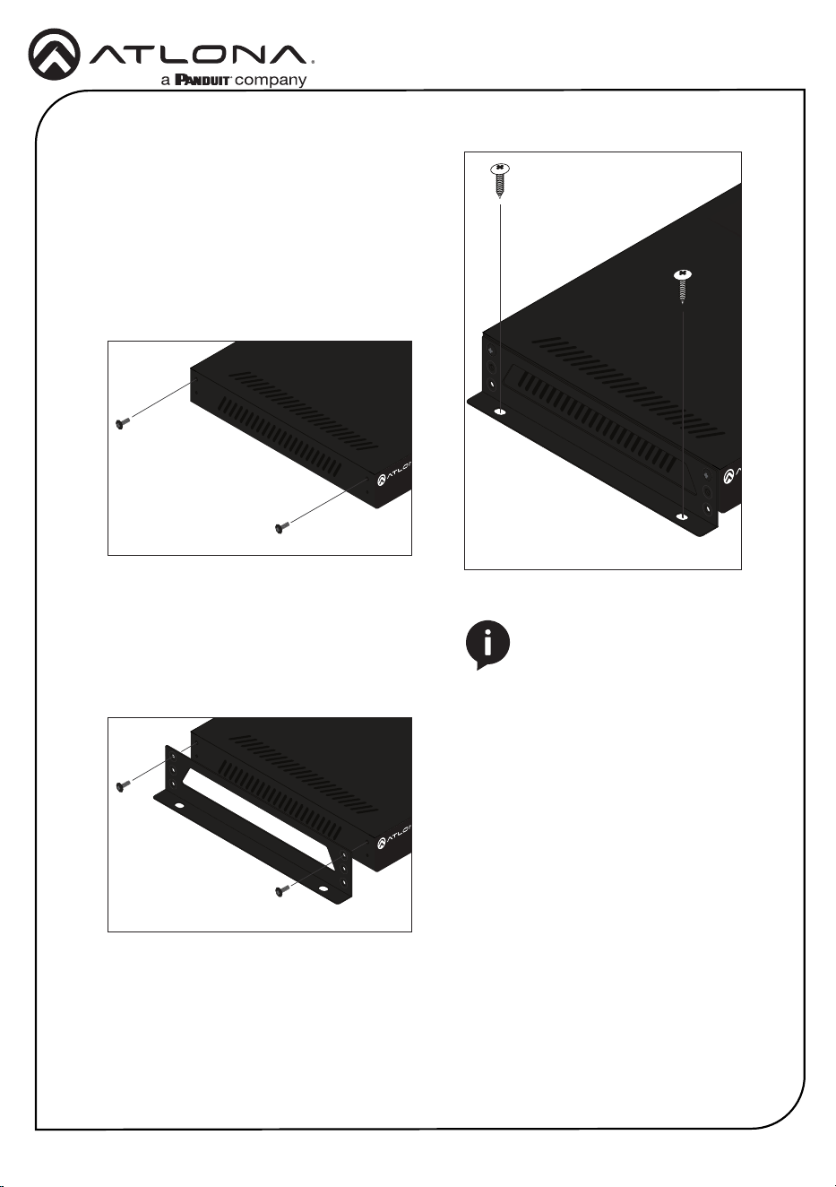
The AT-JUNO-451 includes two mounting
brackets, which can be used to attach the unit
to any at surface. Use the two enclosure
screws, on the sides of the unit to attach the
mounting brackets.
1. Using a small Phillips screwdriver, remove
the two screws from the left side of the
enclosure.
2. Position one of the mounting brackets, as
shown below, aligning the holes on the
side of the enclosure with one set of holes
on the mounting bracket.
3. Use the screws from Step 1 to attach the
mounting bracket.
4. Repeat steps 1 and 2 to attach the
second mounting bracket to the opposite
side of the unit.
5. Mount the unit to a at surface using the
oval-shaped holes, on each mounting
bracket. If using a drywall surface, a #6
drywall screw is recommended.
POWER INPUT FW
1 2 3 4
INPUT
AT-JUNO-451-HDBT
J
UNO
X
TM
POWER INPUT FW
1 2 3 4
INPUT
AT-JUNO-451-HDBT
J
UNO
X
TM
POWER INPUT FW
1 2 3 4
INPUT
AT-JUNO-451-HDBT
J
UNO
X
TM
NOTE: Mounting brackets can
also be inverted to mount the
unit under a table or other at
surface.
Mounting Instructions

7
Installation Guide
AT-JUNO-451
Notes
8
Installation Guide
AT-JUNO-451
Version 1 25193-R1
®
The terms HDMI, HDMI High-Denition Multimedia Interface, and the HDMI Logo are trademarks or
registered trademarks of HDMI licensing Administrator, Inc.
English Declaration of Conformity
The English version can be found under the resources tab at:
https://atlona.com/product/at-juno-451/.
Warranty
Chinese Declaration of Conformity 中国RoHS合格声明
To view the product warranty, use the following link or QR code:
https://atlona.com/warranty/.
由SKU列出於:
https://atlona.com/about-us/china-rohs/.
© 2023 Atlona Inc. All rights reserved. “Atlona” and the Atlona logo are registered trademarks of Atlona Inc. All other brand names and trademarks or registered
trademarks are the property of their respective owners. Pricing, specications and availability subject to change without notice. Actual products, product images, and
online product images may vary from images shown here.
US International
atlona.com • 408.962.0515 • 41.43.508.4321