
1

2
The main provisions
Statement of rights and responsibilities All rights belong to ZKTECO CO., LTD. and they are protected
by the laws of the People's Republic of China. No person may use the trademark without the written
permission of the company, and no person may copy or distribute this manual. 1) We are not
responsible for failures caused by improper operation. Due to frequent updates, this manual may have
slight differences from the actual product, please note. 2) We do not issue any additional notices if the
user manual is updated.
Radiation Safety Regulations 1) The ZKX series X-ray inspection television systems meet the criteria of
the internal radiation safety standard, it is harmless to humans and the environment. 2) The
inspection X-ray television systems of the ZKX series guarantee the safety of the ISO1600 (33DIN)
film.
Contacts Company: ZKTECO CO., LTD. Address: ZKTeco Industrial Park, 188 Industrial Avenue,
Pingshan, Dongguan, Guangdong Province, China. ZKTeco office, Wuhe road, BanTian, Longgang
County, Shenzhen. Website: www.zkteco.com E-mail: [email protected]
Regulatory documents
In the manufacture of inspection X-ray television systems of the ZKX series, the following
requirements are taken into account: GB 15208.1-2018 (GB15208.1-2018) Micro-dose X-ray
security inspection system -- Part 1: General technical requirements; GB/T 191-2008 packaging storage
and transportation icon; GB/T 2423.1-2008 Environmental testing of electric and electronic products -
Part 2. Test methods Test A. Low temperature; GB/T 2423.2-2008 Environmental testing of electrical
and electronic products - Part 2. Test methods Test B. High temperature; GB/T 2423.3-2016
Environmental testing - Part 2. Test method test Cab. constant damp heat test; GB/T 2423.5-1995
Environmental testing for electric and electronic products - Part 2. Test methods Test Ea and guide.
Impact; GB/T 2423.10-2008 Environmental testing of electric and electronic products - Part 2. Test
method test Fc. Vibration (sinusoidal); GB/T 4208-2017 enclosure protection grade (IP code); GB
4793.1-2007 Safety requirements for electrical equipment for measurement, control and laboratory -
Part 1. General requirements; GB/T 9254-2008 Radio disturbance limits and methods of measurement
for information technology equipment; GB/T 17626.2-2006 Electromagnetic compatibility test and
measurement technology Electrostatic discharge immunity test; GB/T 17626.3-2016 Electromagnetic
compatibility test and measurement technology RF electromagnetic field radiation immunity test; GB/T
17626.4-2008 Electromagnetic compatibility test and measurement technology Electrical fast transient
burst immunity test; GB/T 17626.5-2008 Electromagnetic compatibility test and measurement
technology Surge (impact) immunity test; GB/T 17626.6-2008 Electromagnetic compatibility test and
measurement technology Conducted disturbance immunity of RF field induction; GB/T 17626.11-2008
Electromagnetic compatibility test and measurement techniques Immunity to voltage dips, short
interruptions and voltage changes test; GB/T 17799.1-2017 Electromagnetic compatibility common
standards Immunity in residential, commercial and light industrial environments; GB/T 17799.2-2003
Electromagnetic compatibility general standard immunity test in industrial environment; GB/T
17799.3-2012 Common standards for electromagnetic compatibility, emissions in residential,
commercial and light industrial environments; GB/T 17799.4-2012 Electromagnetic compatibility
general standard emission in industrial environment.

3
Preface
Dear customers, thank you for choosing the inspection X-ray machine. our company's system. This
manual provides operating instructions, information on product safety, manufacturing, image reading
processes, a description of menu options, and a frequently asked questions section. In this guide, you
will learn how to operate, configure, and maintain this product, following international safety standards
for X-ray equipment. Thus, it is absolutely safe for the operator and the environment.
Goal
This guide can help the operator to operate the X-ray correctly. a system manufactured by our
company. Before you start, we strongly recommend that you read this guide carefully.
Application
This guide is applicable to:
1) System operators
2) System administrators
3) The service organization of the systems
GENERAL REQUIREMENTS FOR THE RECRUITMENT AND TRAINING OF PERSONNEL
The user of an ionizing radiation source (hereinafter referred to as the AI), an organization that
performs work and (or) provides services to the users of the AI that may affect radiation safety, must
be staffed with personnel trained in the safe operation of the AI (radiation device) in all modes prior to
the start of work and during work with the AI, and also, the implementation of actions aimed at
preventing a radiation accident and a radiation incident, responding in the event of a radiation accident
and a radiation incident.
The requirements for the number, composition and qualifications of personnel are established by local
legal acts and (or) organizational and administrative documents of the AI user, the organization
performing work and (or) providing services to AI users that may affect radiation safety, taking into
account the technical (operational) documentation for AI and methods (technologies) of performing
work from the III.
The list of persons classified as "personnel" should be documented by the user of the AI and the
organization performing work and (or) providing services to users of the AI that may affect radiation
safety.
The duties of personnel in the field of radiation safety and the procedure for staff admission to work
with AI are determined and documented by the AI user and the organization that performs work and/or
provides services to AI users that may affect radiation safety.
Before being allowed to work and periodically, personnel must undergo occupational safety training,
including radiation safety issues in accordance with the procedure established by labor protection
legislation.

4
Content
1 Notification of safe operation 6
1.1 Film safety 6
1.2 Safety check before commissioning 6
1.3 Basic safety rules 6
1.4 Radiation protection 6
2 Product Presentation 7
2.1 Operating principles 7
2.2 Technical index / Main parameters 8
2.3 Features 10
2.4 Intended use 10
3 Description and operation 11
3.1 Enabling 11
3.2 Inspection of items 12
3.3 Shutdown 13
3.4 Emergency stop indicator and button 13
3.5 Special keyboard 15
3.6 PC keyboard and mouse 17
4 Working with the software and image processing 19
4.1 Main interface 19
4.2 System software 19
4.3 Information section 20
4.4 Functional section 20
4.5 Image processing 21
4.5.1 B/W and color. (Black and white and color image) 21
4.5.2 Deep Scan 21
4.5.3 Surface scanning 22
4.5.4 Detailed image 22
4.5.5 Organics 22
4.5.6 Inorganics 22
4.5.7 Inversion 22
4.5.8 Absorption Management 23
4.5.9 Dynamic scanning 23
4.5.10 Pseudocolor 23
4.5.11 Suspect organic factor Z789 (techn.) 23
4.6 System Options 24
4.7 Image 24
4.7.1 Preview 24
4.7.2 Image settings 27
4.8 User Management 28
4.8.1 Account settings 28
4.8.2 Change password 30
4.8.3 Auto-login 30
4.9 Managing Logs 31
4.9.1 Launch log 31
4.9.2 Session log 31
4.9.3 Radiation Emission Log 32
4.10 TIP(Threat Imitation Training) 33
4.10.1 TIP strategy 34
4.10.2 TIP Images 35
4.10.3 TIP Examination 35
4.11 Training 36
4.11.1 Setting parameters 36

5
4.11.2 Control Panel 36
4.11.3 Training process 36
4.12 System settings 37
4.12.1 Intelligent Detection 37
4.12.2 Keyboard 37
4.12.3 Setting up counters 38
4.12.4 Other 39
4.13 System information 39
4.14 Exit and shutdown 40
5 Maintenance 41
5.1 Daily maintenance 41
5.1.1 External surface of the equipment 41
5.1.2 Display, photoelectric sensor and control panel 41
5.1.3 Photoelectric sensor 41
5.1.4 Conveyor check 42
5.1.5 Inspection of curtain at entrance and exit 42
5.2 Monthly Check 42
5.2.1 Inspection of the Emergency Button 42
5.2.2 Photoelectric sensor 42
5.3 Quarterly inspection 42
5.3.1 Inside the equipment 42
5.3.2 Inspection of indicators 43
5.4 Annual inspection 44
5.5 Recommended periods for scheduled preventive maintenance 45
5.6 Storage conditions 47
5.7 Troubleshooting 48
Error 1: The equipment does not start by pressing the button 48
Error 2: The conveyor does not move 48
Error 3: "Self-diagnostic system error" on the screen 48
Error 4: Keys on the special keyboard do not work 49
Error 5: Incorrect radiation 49
Error 6: Power failure 49

6
1 Notification of safe operation.
We recommend that this manual be read by the operator before starting the system for the safest
operation of the introscope.
1.1 Film safety
The imaging films used in our X-ray inspection system comply with ISO1600 safety standards.
1.2 Safety check before commissioning.
Before connecting the system to the power supply, make sure that:
1) Check the lead coating, do not start the system in case of a coating violation.
2) Check if the photovoltaic sensors are blocked.
3) Check the conveyor belt for jamming, whether there is dirt or a tear on it.
4) Check the case, monitor, panel and electrical cables for defects.
5) Make sure that the housing cover is closed.
Please note: when switching on for the first time, clause 3.1 Switching on 5 minutes after
warming up, it is necessary to conduct a primary radiation monitoring check according to
clause5.4. Annual inspections. Record the results of the audit in the annual audit log.
1.3 Basic safety rules.
For safe operation of the system, please follow the rules:
1) Familiarize yourself with the basic radiation safety requirements.
2) The operator is familiar with the safety requirements.
3) If the system has not been used for more than 6 months, perform a thorough check.
4) Installation and installation, connection, replacement of components are performed by the service
organization.
5) Operation is prohibited if the housing, conveyor belt or electrical cable is damaged.
6) Only the maintenance company is allowed to open the case and replace the components.
7) Do not make arbitrary changes to the security system configuration.
8) It is forbidden to expose living objects to the X-ray radiation of the inspection system.
9) Do not extend any body parts inside the housing or tunnel during operation.
10) If liquid enters the system body, stop its operation immediately.
11) All connections, earthing, etc. must be made correctly.
1.4 Radiation protection.
We apply reliable radiation protection measures on our products to ensure the safety of the operator
and users.:
1) Only when the generator is under high voltage, it emits X-rays. Therefore, there is no radiation
during transportation or storage.
2) Lead panels are installed around the machine, the tunnel entrance and exit are equipped with a
lead curtain, they protect against radiation leakage into the environment.
3) The device is equipped with an effective grounding, which protects the operator from electric
shock.
4) The device has a built-in overload, overvoltage and radiation leakage prevention system.
5) Active blocking will not allow the radiation generator to start.
7
2 Product Presentation
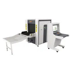
2.1 Operating principles
The introscope is divided into five parts: a conveyor, a radiation generator with a control board,
indicators, factory circuit boards and an electric drive.
The objects enter the inspection tunnel on a conveyor belt, which is started after the object interacts
with photoelectric sensors (sensors).
When the items enter the tunnel, the sensor will signal the start of the inspection.
The control board initiates the emission of radiation by the generator.
The beam penetrates through objects and is partially absorbed by them, the beam receiver processes
the residual radiation.
After that, the receiver converts it into a digital signal and sends it to a computer.
Using the detailed image algorithm, a clear image of objects will be displayed on the screen.
Figure 2-1 System operation process
Figure 2-2 Stages of work inside

8
2.2 Technical index / Main parameters
Main parameters of the system models (introscopes)
Model
(ZKX series)
5030А
5030С
6040
6550
8065
10080
100100
Unit
Energy
system
Two.
Energy
system
Two.
Energy
system
Two.
Energy
system
Two.
Energy
system
Two.
Energy
system
Two.
Energy
system
Main parameters
Tun
nel
size
Width,
mm
507
507
608
660
805
1004
1008
Height
, mm
305
305
405
510
660
806
1005
Maximum
distributed
load weight
150
150
150
180
200
220
220
Service life
30 000ч
Current
strength (mA)
0.5-1.0
Voltage
140кV-160кV
Cooling
method
Oil 100%
Limit state
criteria
The amount of radiation is reduced to 80% of the required amount
Dose of
ionizing
radiation
during
scanning
≤1.0 µGy
Environmental
conditions
Storage
temperature
-40±2℃~+60±2℃/5%~95%( No condensation)
Operating
temperature
0℃±2℃~+40±2℃/5%~95%( No condensation)
Nutrition
AC220V(-15%~+10%),50Hz±3Hz
Power
consumption
≤0,5 kW
≤0,8 kW
≤1,0 kW
≤1,5 kW
≤1,5 kW
Noise level
≤55dB
Image
processing
system
Image
processing
Pseudocolor, shades of gray, deep scan, surface scan, detailed scan, inorganic
highlight, organic highlight, dynamic scan, color inversion, etc.
Memory
Over 100,000 images
System
functions
High Density Warning, Drug and Explosives Check, Date/Time, Baggage Counter,
User Management, Recognition, Training, etc.

9
Main parameters of the models of the system (introscopes) with two generators
Model
(ZKX series)
6550D
8065D
10080D
100100D
Two. Energy
system
Two. Energy
system
Two. Energy
system
Two. Energy
system
Main parameters
Tun
nel
size
Width,
mm
660
805
1004
1008
Height,
mm
510
660
806
1005
Maximum
distributed
load weight
180
200
220
220
Service life
30 000ч
Current
strength (mA)
0.5-1.0
Voltage
140кV-160кV
Cooling
method
Oil 100%
Limit state
criteria
The amount of radiation is reduced to 80% of the required amount
Environmental
conditions
Storage
temperature
-40±2℃~+60±2℃/5%~95%( No condensation)
Operating
temperature
0℃±2℃~+40±2℃/5%~95%( No condensation)
Nutrition
AC220V(-15%~+10%),50Hz±3Hz
Power
consumption
≤1,0кW
≤1,3кW
≤1,6кW
≤1,6кW
Noise level
≤55dB
Image
processing
Image
processing
Pseudocolor, shades of gray, deep scan, surface scan, detailed scan, inorganic highlight,
organic highlight, dynamic scan, color inversion, etc.
Memory
Over 100,000 images
System
functions
High Density Warning, Drug and Explosives Check, Date/Time, Baggage Counter,
User Management, Recognition, Training, etc.

10
2.3 Features
Our company's introscopes have the following characteristics to provide users with greater security,
convenience, and fast service.
◼ Eco-friendly design: the lead-free surface of the protective curtain prevents leakage and does not
pollute the environment.
Safer: radiation monitoring protects against harmful leakage.
◼ Turn off by pressing: When you turn the key, the device will turn off automatically, quickly and
conveniently.
Fault self-diagnosis: The system will detect the fault itself and report it to simplify troubleshooting.
◼ Special keyboard: image manipulation functions, on and off, and so on.
Dynamic features: Work with both static and dynamic images.
2.4 Intended use
X-ray inspection equipment, uses the latest image processing technology, higher resolution, clearer
image, higher permeability. It can quickly and efficiently detect various dangerous goods and
suspicious substances with high density. It is suitable for checking small hand luggage, suitcases, bags,
etc.
The introscope is used in government offices, embassies, airports, conference centers, exhibition
centers, tourist destinations, post offices, shopping malls and hotels.
They can be placed in rooms providing the operating parameters of the environment. 0℃±2℃~
+40±2℃/5%~95%( Non-condensing) according to the project.
11
3 Description and operation
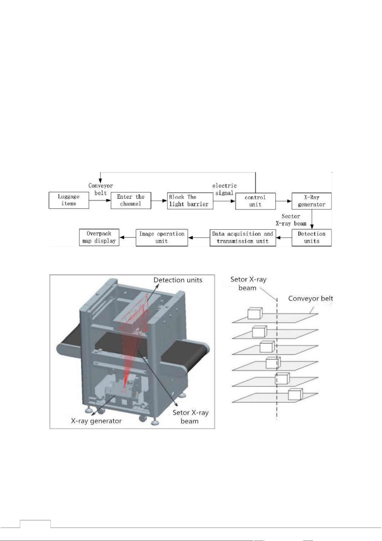
3.1 Enabling
Step 1: Insert the power cable into the outlet (make sure that the network configuration and
grounding are in order).
Figure 3-1 model ZKX5030
Figure 3-2 model ZKX6550
12
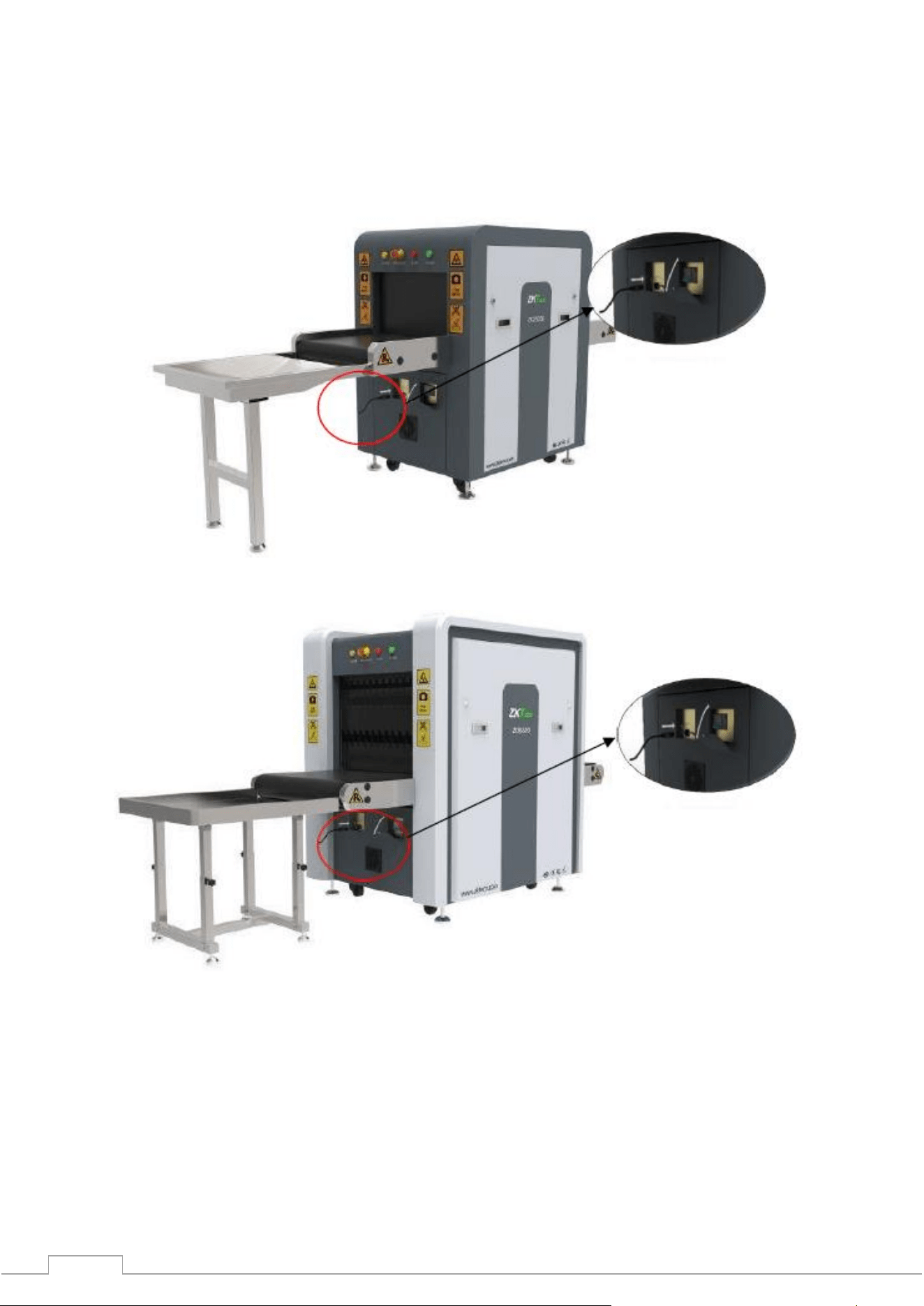
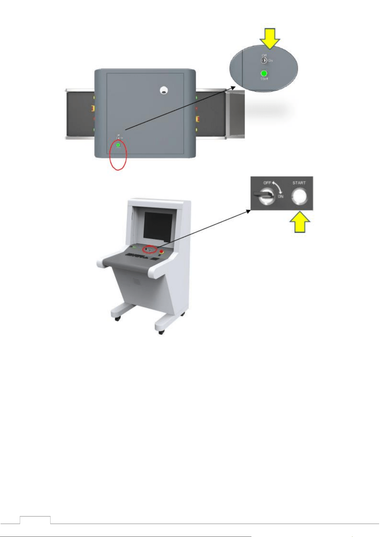
Step 2: Insert the key into the power lock and turn it to the "ON" side.
Figure 3-3 version on the case
Fig. 3-4 option on the control panel
Step 3: Press the start key next to the lock. The color will turn green.
Step 4: The system will start warming up automatically, this is necessary to protect the generator and
takes from 1 to 5 minutes. After warming up, the system is fully ready for scanning processes.
Please note: when switching on for the first time, 5 minutes after warming up, it is necessary to
perform an initial radiation monitoring check according to5.4. Annual inspections. Record the
results of the audit in the annual audit log.
3.2 Inspection of items
Setup items: The item must be placed on a conveyor belt, as shown on the signs.
Verification: When an object enters the tunnel, its scanned image will appear on the monitor. Different
colors show different materials. The directional arrows on the control panel or in the program
window allow you to change the direction of the conveyor.
Step 1: Place the object in front of the tunnel entrance. Step 2: Press the Forward key.
Step 3: When the object enters the tunnel, the radiation emission indicator (red) will light up.
Step 4: Pick up the item at the exit of the tunnel.
13
3.3 Shutdown
Step 1: Stop the conveyor belt, turn the key to the "OFF" position, the indicator light next to it should go
out (the green indicator light will go out in a minute).
Step 2: Disconnect the machine from the external power supply. Pull the key out of the lock.
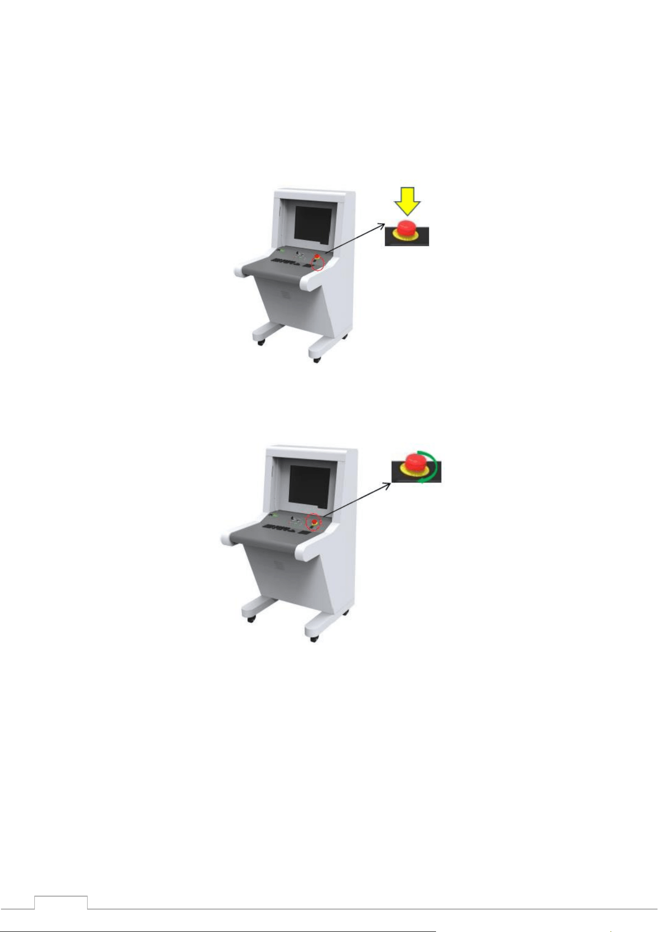
3.4 Emergency stop indicator and button
Emergency stop button: In an emergency, press any emergency button to stop the emission of
radiation and the conveyor belt.
Fig. 3-5 extra. Button
Please note: When you need to be restored to normal system operation (cancel emergency
mode), turn the pressed emergency button clockwise to pull it back out and press the start
button to continue.
Figure 3-6 Recovery
Please note: Recovery requires pressing the start button.
14
Figure 3-7 Start button
Power indicator (green): When the system is running, the green indicator is on.
Radiation indicator (red): When radiation is emitted, the red indicator lights up.
15
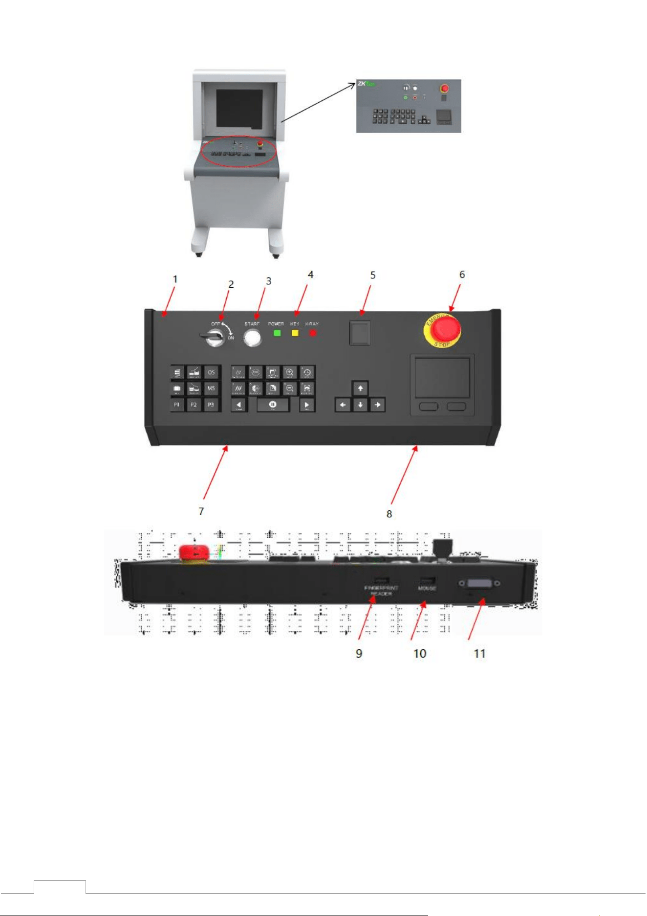
3.5 Special keyboard
Figure 3-8 special keyboard
1- External cover of the valve, 2 - Power lock, 3 - Start button, 4 – Indicators, 5 - OTP reader. Finger, 6 -
The extra button. stop., 7 - Keyboard area, 8 - Touch pad (functional mouse), 9 - USB reader socket, 10
- USB mouse socket, 11 – DB15 socket
16
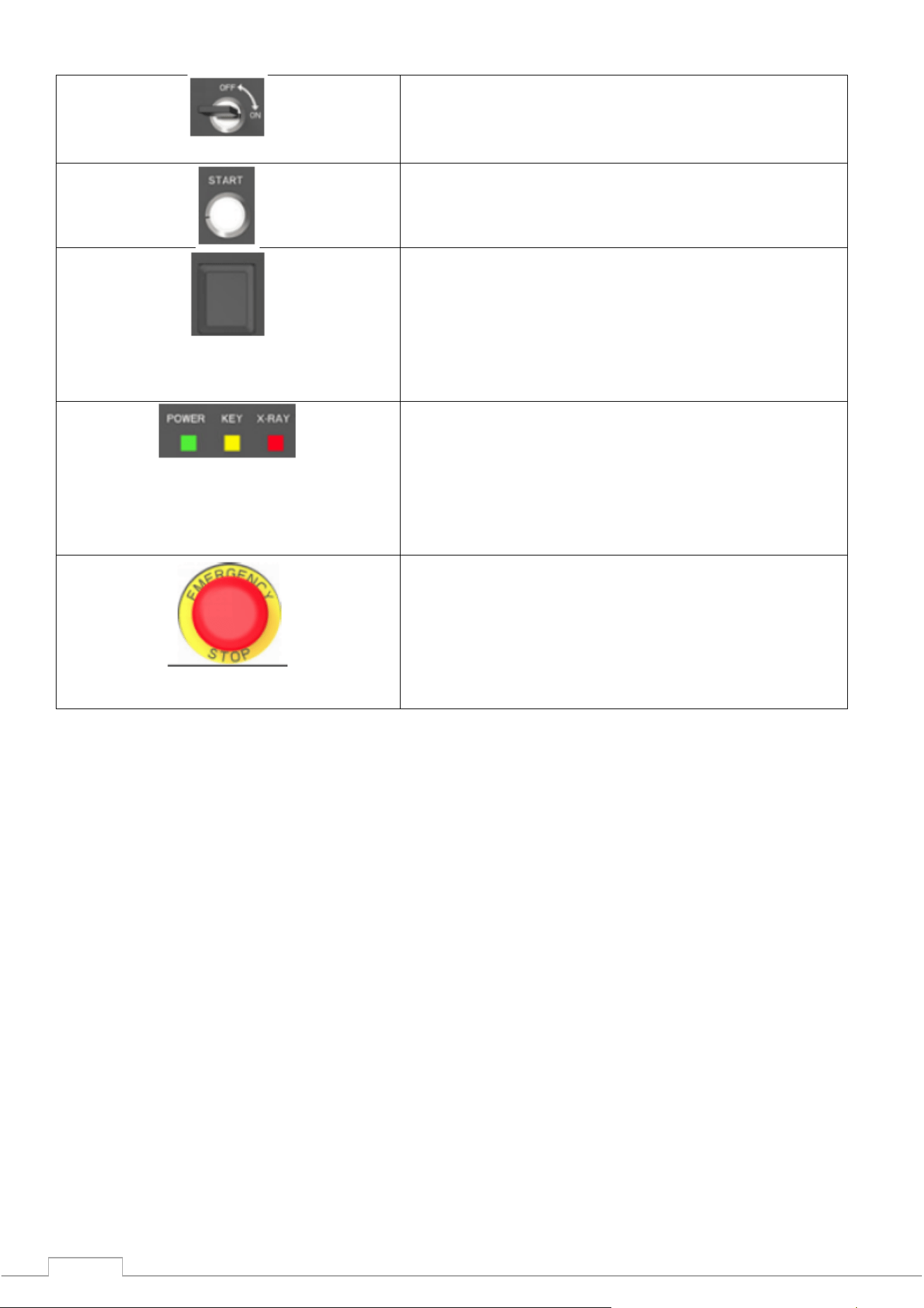
Explanation of electrical components and keyboard
Switch-on lock: The main lock for monitoring the
power supply of the equipment.
It is also necessary to restrict unauthorized access to
management.
Start button: Pressing will start the system, the green
indicator will light up
Fingerprint reader: A reader for verifying users,
logging into an account, and registering new users.
The green color of the indicator on the reader
indicates that the fingerprint is in the database. Red
indicates that the fingerprint has not been registered.
The reader has its own fingerprint storage - up to a
maximum of 65,535 users with 10 fingerprints each.
Indicators:
(I) Radiation (red): The emission of radiation is
shown in red, the indicator goes out when the
radiation stops.
(ii) Power supply (green): The indicator will show
when the equipment is working. A dimmed indicator
means that the equipment is turned off.
Emergency stop button: In case of an emergency
, press this button immediately. The emitter and the
conveyor will stop working immediately. Since the
button belongs to the blockers, the restoration of
normal operation is performed after removing the
lock. Turning the button clockwise will reset it to its
original state.
17
Keyboard (control, image manipulation, menu)
(I) The conveyor control buttons: "Forward" or
"Backward" will make the conveyor move in the
desired direction. Pressing the Stop key will stop the
conveyor.
(II) Image Window Move/Navigation Keys: When the
image is zoomed in or out, the preview window will
automatically appear in the lower right corner. Click in
any direction to move the window. The keys can also
be used to navigate the menu.
(III) Function presets: For presets, please refer to
"4.12.2 Keyboard".
(IV) Menu: Click "Menu" to enter into the system menu.
(V) Mark key: Refer to "4.10 TIP image" for
explanation.
(VI) Image Interaction Keys: Refer to Section
"4.5 Image Processing" for an explanation of the
functionality. The keys are designed to work with the
image.
3.6 PC keyboard and mouse.
Our company's inspection equipment works not only with a special keyboard, but also with a
standard PC keyboard and mouse. On the 5030A and 5030C models, you can choose the interface
methods.
PC presets (quick access)
Function Area(F1-F12)
F1 - P1
F2 - P2
F3 - P3
F4 - Forward
F5 - Stop
F6 - Back
F7 - Image Control
F8 - Pull Forward
F9 - Pull Back
F10 - F1-F12 Key On/Off
F11 - Zoom In
F12 - Zoom Out
Alphabet Area – Image Processing Functions
A - Black & White
B - Invert
C - Organic
D - Inorganic
H - Absorbance+
G - Absorbance-
I - Deep Scan

18
J - Surface Scan
K - Detail
N - Dynamic Scan
M - Menu
R - Original
P – Mark
Direction keys - When zoomed in, move the image window.
↑ - Up
↓ - Down
← - Left
→ - Right
Numeric Keypad - Accounts and Passwords are nothing more than combinations of numbers
Numbers in the range 0-9, just for entering numeric values.

19
4 Working with the software and image processing
4.1 Main interface
View the interface elements using example images:
Fig. 4-1 Main interface
4.2 System software
Fig. 4-2 Control panel in the software
① Main Menu (Refer to "4.6 System Options")
② Image Processing Functions
③ Image Area Management
④ Information Section
20
4.3 Information section
Account Info: After logging in, the current account name will be automatically displayed in the
information section.
Luggage Quantity: Displays the current user, the number of scans, and can also display the total number
of luggage.
Date and Time: Displays the working date and time.
Image Correction:After a long time of operation, there will be slight changes in the generator, which
will negatively affect the image quality. Click "Correction" to restore.
Mode: Scan mode , training .
Device Status: Normal status is displayed as .
On standby
After self-diagnosis, when no problems are detected, the system will show the
status "Ready".
Scanning
During normal operation, when the radiation emission indicator is lit, the
system shows the "Scanning" status.
Error
In case of malfunction or incompatibility of components, the system will show
the "Error" status.
Emergency Stop Button: This button is used in dangerous situations, when pressed, the generator and
conveyor will stop working immediately to ensure the safety of people.
On standby
Normal condition
Emergency
situation
Status when emergency button is pressed
4.4 Functional section
Fig. 4-3
Restore Image: The original can be restored with a keystroke. Press" ", after image processing
to return to the original image.
Conveyor control: Press " " on the screen or the corresponding keys on the special
keyboard to move the belt "Forward", "Stop", "Backward".
Pull image forward, backward: If you need to return to previous scans while working with images, use
the slide functions. Clicking allows you to work with previous images.
Zoom in and out: Press and , to zoom in or out. A total of 64x zoom is possible.
21
Multifunctional keys: Using the combinations described in section "4.12.2 Keyboard", working with
the image can be made easier by presetting keys P1-P3.
Рис. 4-4
4.5 Image processing
(The following images are the images of dual-view series security monitoring system, the horizontal
image is also applicable to the general series security monitoring system, the following figure is the
original image used in image processing)
Horizontal image Vertical image
4.5.1 B/W and color. (Black and white and color image)
Fig. 4-5 Black and white image
All items are displayed using a 256 color palette.
Fig. 4-6 Color image
To make inspection easier, different materials have different display colors. Inorganic - blue, organic -
orange, intermediate - green.
4.5.2 Deep Scan
Enhances the contrast of the dark area
Fig. 4-7 Deep scan image
22
4.5.3 Surface scanning
Enhances the contrast of the light area
Fig. 4-8 Surface scanning image
4.5.4 Detailed image
This function allows you to see both easily and difficultly permeable objects at once. Even if the object
is hidden behind two metal plates, it can be seen.
Fig. 4-9 Detailed image
4.5.5 Organics
The function displays organic objects in black and white (excludes).
Fig. 4-10 Exclusion of organics
4.5.6 Inorganics
The function displays inorganic objects in black and white (excludes).
Fig. 4-11 Inorganic exclusion
4.5.7 Inversion
Inversion makes it easier to detect dense cables.
Fig. 4-12 Inverted image

23
4.5.8 Absorption Management
Adjusts the brightness of the scanned image.
Fig. 4-13 Bright image
Fig. 4-14 Faded image
4.5.9 Dynamic scanning
Images will be displayed dynamically.
4.5.10 Pseudocolor
The single-energy system initially shows images in pseudo-color. The dual-energy system initially
shows the original image. All the examined objects are displayed at different color levels of the
spectrogram, and the color represents the actual degree of absorption of X-rays by the object.
4.5.11 Suspect organic factor Z789 (techn.)
The atomic number of explosives and drugs is within the range of [7,9], the function of detecting
suspicious organics is to highlight the substances with suspicious organics in bright red, and other
substances will be displayed in gray. Applicable when inspecting suspicious substances for similarity
with explosives or drugs. The Z789 function can be used by pressing the "E" key on the special
keyboard or the normal keyboard.
24
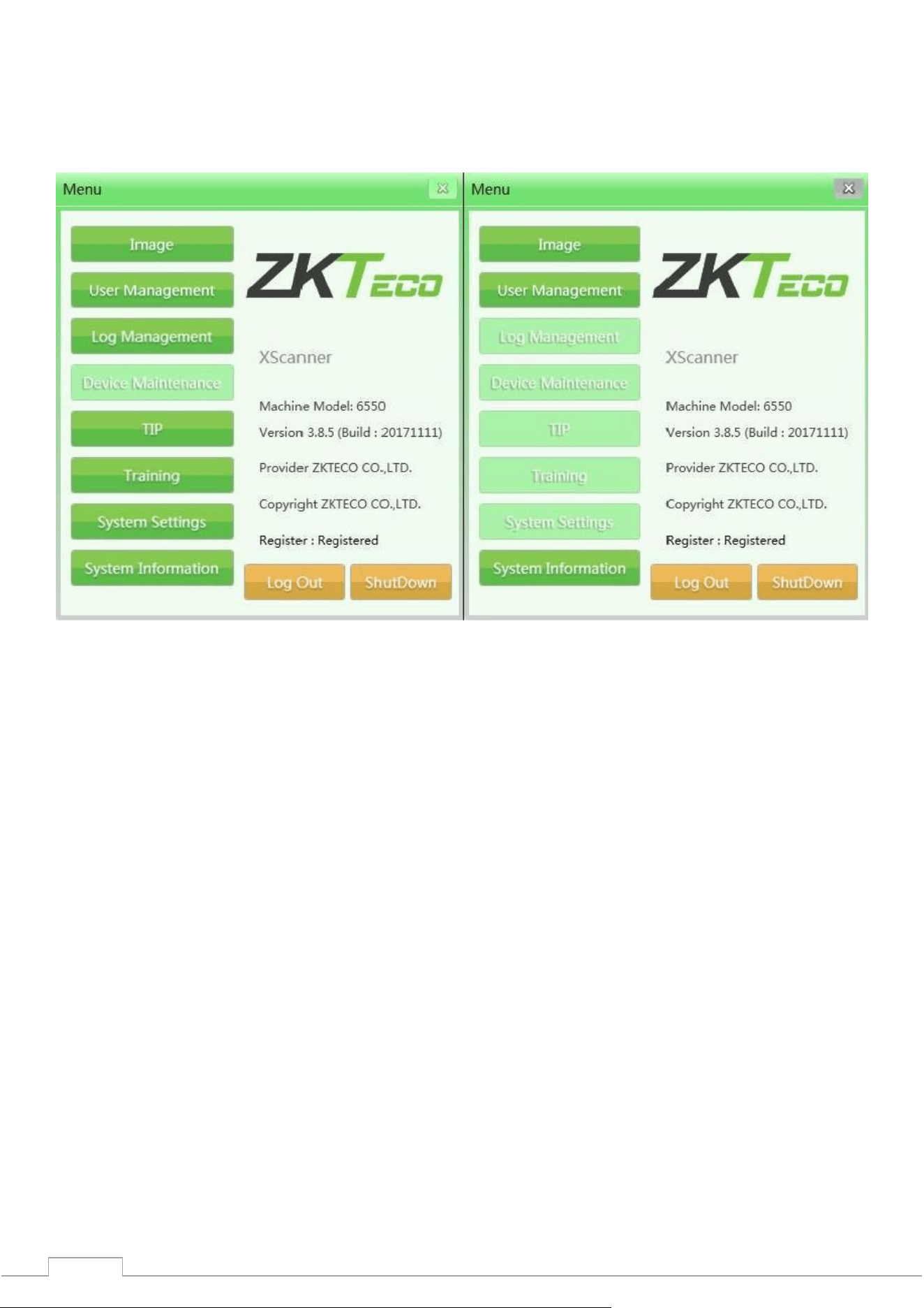
4.6 System Options
There are two categories of users in the system: administrator and operator, with different sets of
control rights. The operator can only change the image settings and change the password of his
account. The administrator can change all settings, except for the "Maintenance" section.
Fig. 4-15 View of the administrator and operator menu.
4.7 Image
This section contains image settings and preview.
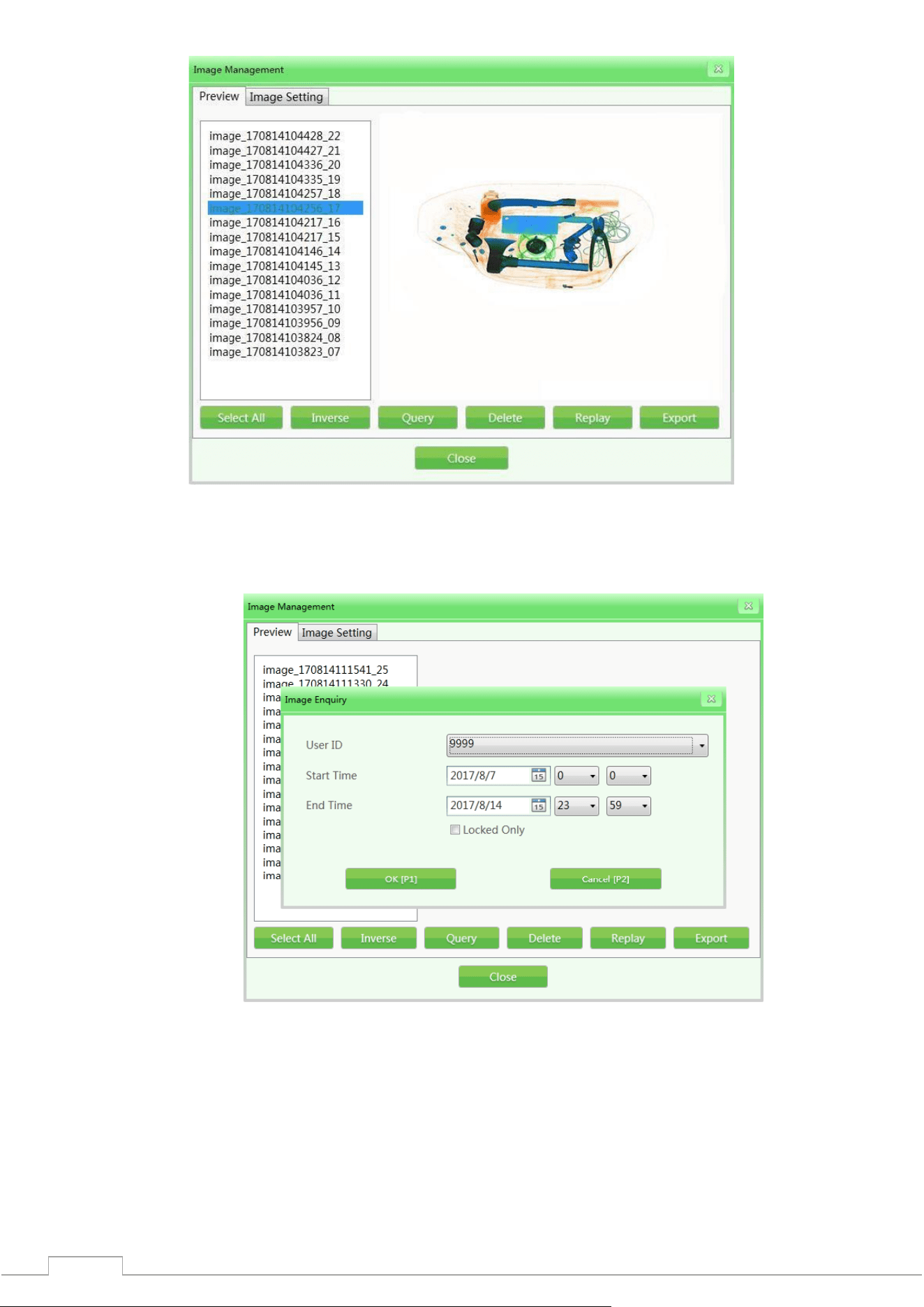
4.7.1 Preview
Single click will open the image list, the small image will appear on the right.
All images created after scanning (primary scanning) will be automatically saved to the hard disk of
the scanning equipment. The preview interface will display the first 16 images. The storage order of
image files will be arranged in chronological order.
25
Fig. 4-16 Image Preview
(Example: The default name of the images is: image + scan time + serial number, for example -
image_170814104217_16)
1) Image request: During the check, you can request previous images.
Fig. 4-17 Image request
2) Delete: Authorized user category can delete images.
3) Repeat: When selecting the function, the specified images will be displayed in the main
interface.
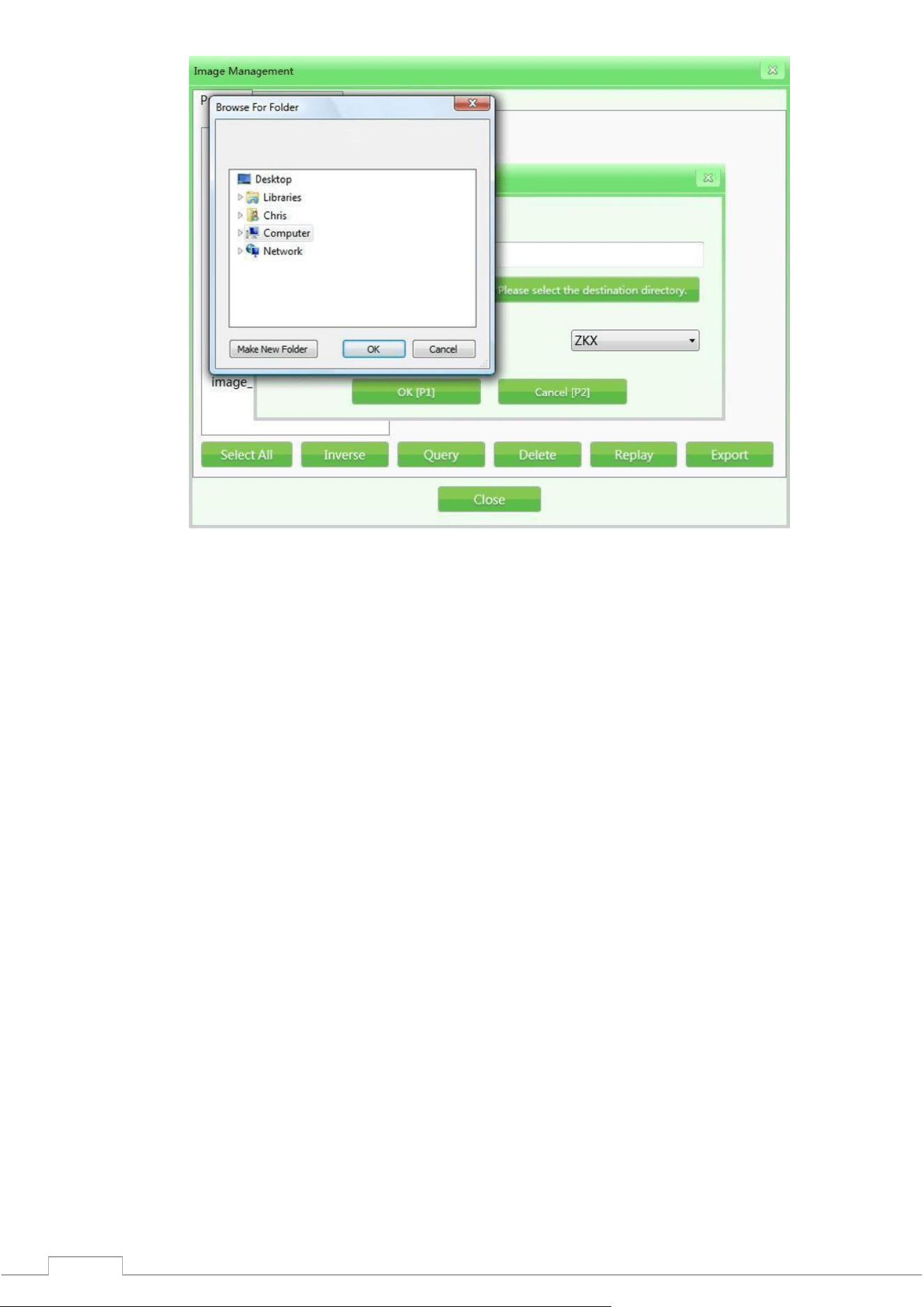
4) Export: If you need to export images to another device, click "Export", connect the storage
medium (such as USB flash drive), and specify the images to be transferred (available formats:
ZKX, BMP and JPG).
26
Fig. 4-18 Exporting images
Please note: Images transferred in BMP or JPG format can be opened in standard Windows
applications or other software. If images are transferred in ZKX format, they can only be read
by the ZKXScanner application.
27
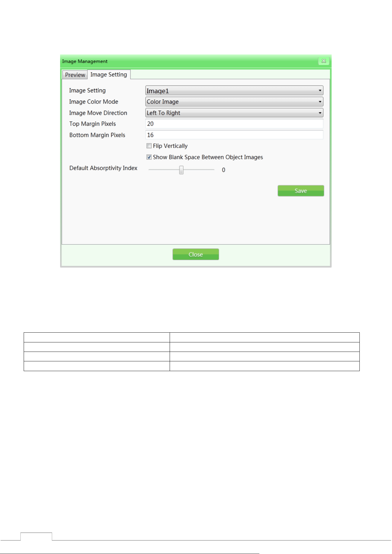
4.7.2 Image settings
The selected image setting will be applied to the image in the display interface in real time. The
original settings have been completed in production, it is not recommended to change them.
Fig. 4-19 Image adjustment
1) Image Setting: Includes Image 1 and Image 2 (for dual-screen display). You can set two images
separately, which will be displayed on two different screens. If your equipment is single-screen, you can
only select one image.
2) Color Mode: Image Color refers to the color mode of the display during scanning.
Including:
(I) Black and white image
(V) Organic
(II) Color image
(VI) Suspect organic factor Z7
(III) Pseudocolor 1
(VII) Suspect organic factor Z8
(IV) Inorganic
(VIII) Suspect organic factor Z9
For image effects, please refer to "4.5 Image Processing".
3) Image Flow Direction: The image of the scanned baggage can be flipped from left to right or right to
left.
4) Large/Small Pixels: The setting range of pixels in the scanning area on the screen will be different for
different models and configurations. The larger the setting value, the larger the pixel area of the marker
(white edge).
5) Flip Vertically: Flip vertically of parcel images scanned in the main interface.
6) Gap Between Objects: Allows you to add spaces between the images of scanned objects so that the
operator can clearly identify the processed images before and after.
7) Absorptivity Index: Absorptivity index reflects the ability to display details of different objects
depending on the material and thickness. The function can brighten/darken the entire image (similar
to fine-tuning deep/shallow scanning). The lower the absorbency level, the brighter the image will be,
and increasing it will have the opposite effect. The initial level is 50, which means the working range is
-25~+25. The “absorptivity-” and “absorptivity+” keys on the keyboard are responsible for decreasing
and increasing the absorbency, respectively.
28
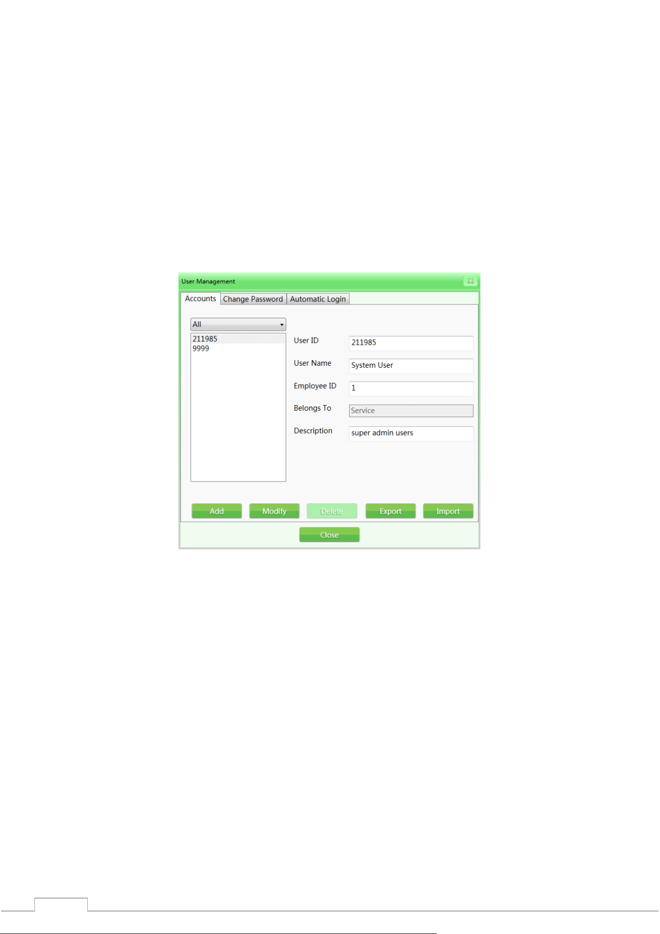
4.8 User Management
With this function, the administrator can add and edit operator accounts, delete, reset passwords
independently. Our software uses a two-level system of user rights. Administrators have more rights,
while operators are limited only to changing information within their accounts.
Please note:
The username must not exceed 6-digit numeric values, from 1 to 999999.
The password must not exceed 8-digit numeric values, from 1 to 99999999.
The default password for a new account is 123456.
4.8.1 Account settings
Fig. 4-20 Accounts
Add: Click on "Add" to create a new account. User ID and password can be up to 8 characters long. The
fingerprint reader contains a data storage capacity of up to 65,535 users with 10 fingerprints each.
29
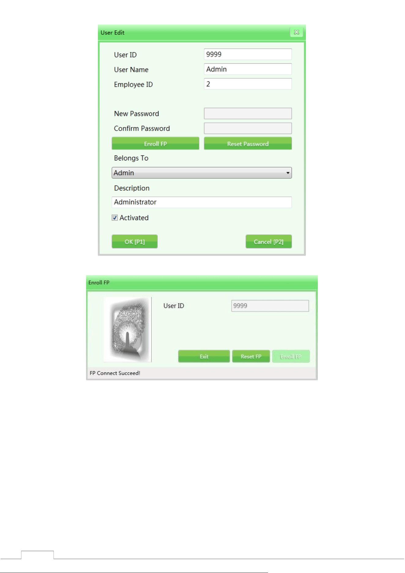
Fig. 4-21 User editing interface
Fig. 4-22 Registering a fingerprint
1) Modify: Click “Modify” to enter the editing interface and modify the user information.
2) Delete: Click “Delete” to delete the user (operator) who is no longer in the system.
3) Import/Export: This function allows the administrator to import/export data (only for ZKX series,
the data is in XML format).
Please note: Once a user account is deleted, it cannot be restored in the future. Please exercise
caution when deleting.
30
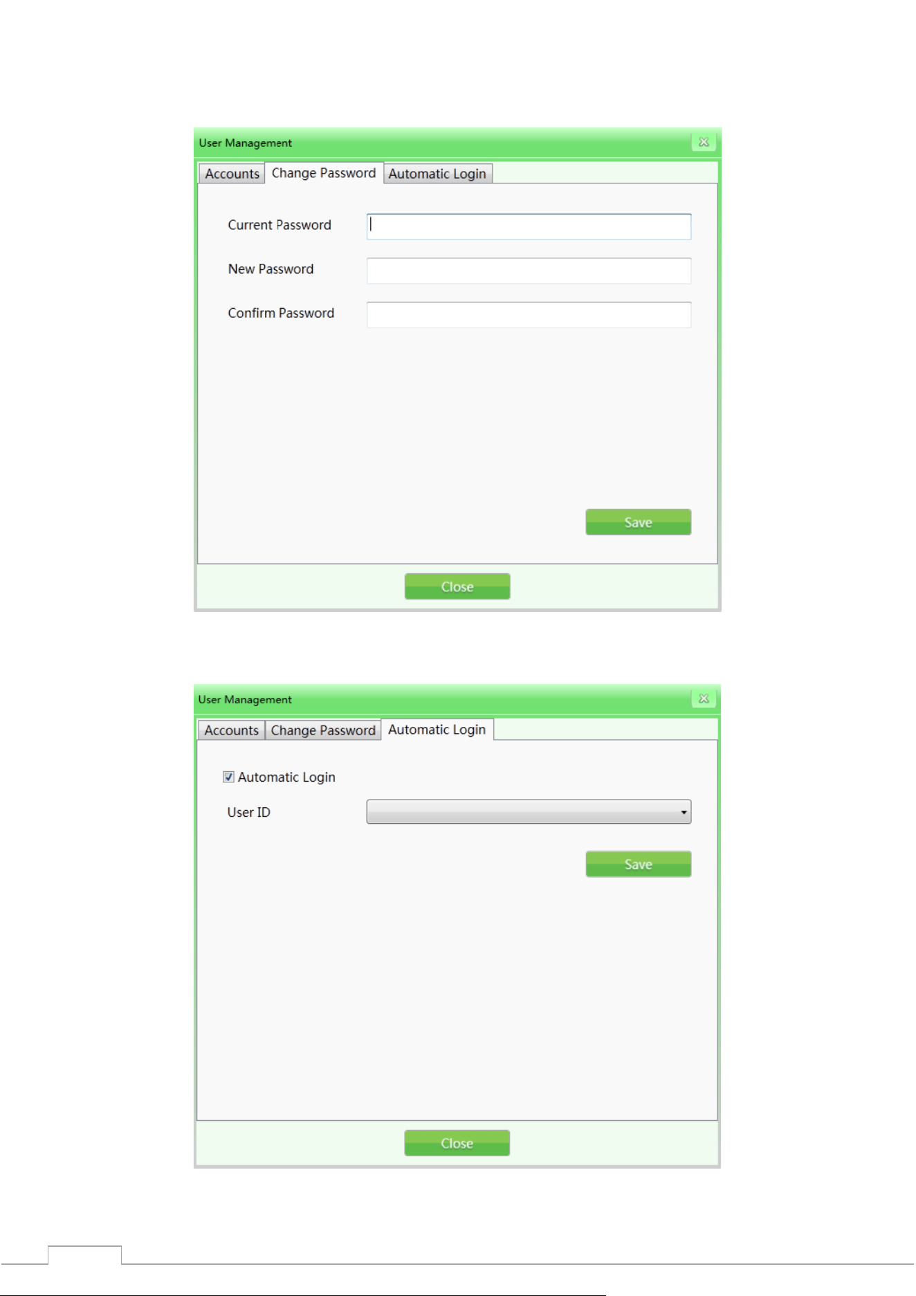
4.8.2 Change password
If you need to change your password, enter the current password and the new password twice in the
required tab.
Рис. 4-23 Смена пароля
4.8.3 Auto-login
Enable/disable the automatic login to the specified account when powered on.
Fig. 4-24 Auto-login
31
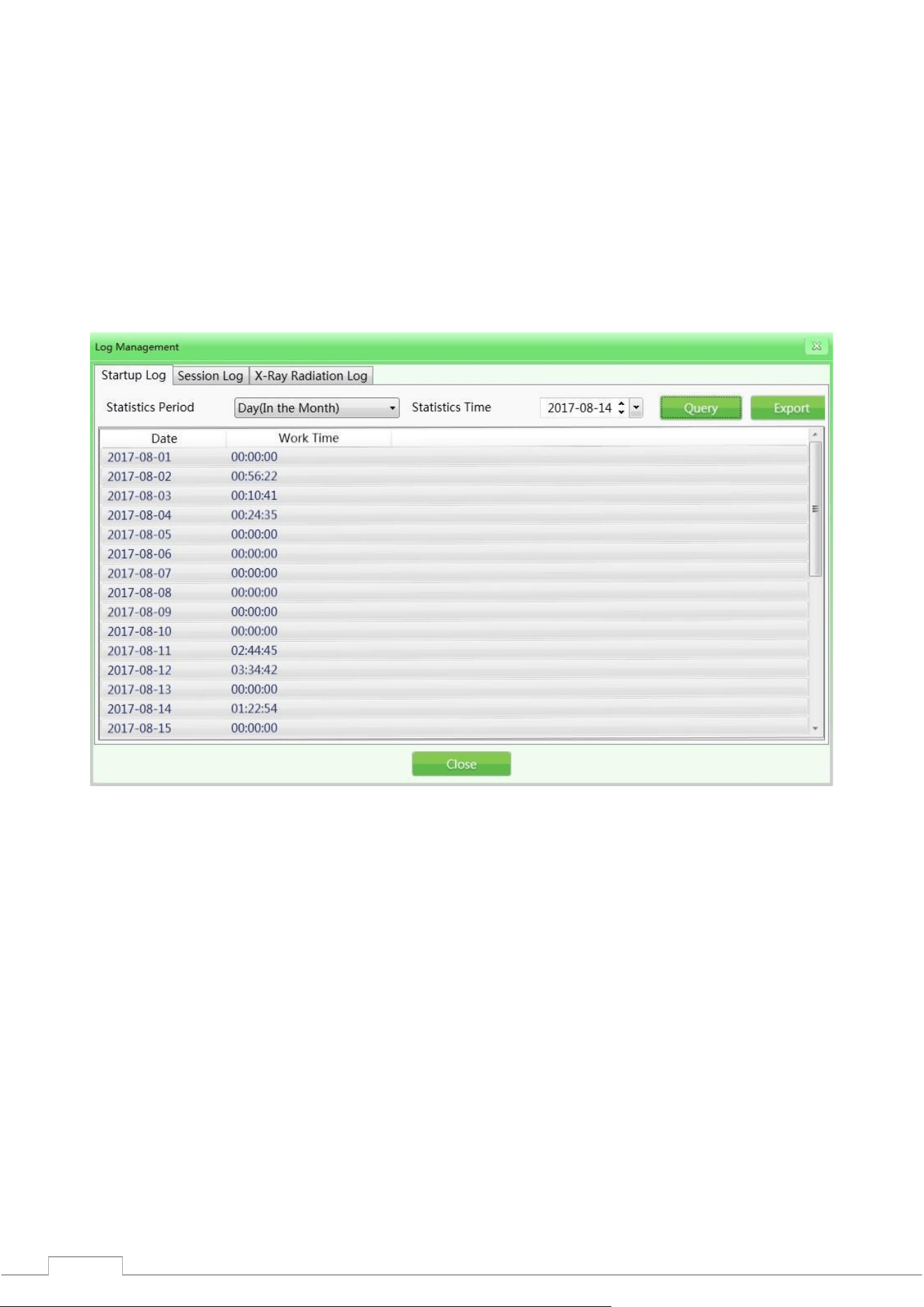
4.9 Managing Logs
This function is available to administrators so that they can access reports, statistics, operator work
results. Management includes: three types of logs, such as "Startup Log", "Session Log" and "Emission
Log". You can request operator work data to assess compliance with work requirements.
4.9.1 Launch log
Device Operation Time Record: You can request data by week (per year), month (per year) and season
(per year). Static time indicates the start time of each period.
Export Records: The user can select one or more records to export. The data will be transferred as a
CSV file. Example: Enter the statistical period - day (per month), 2017-08-14, then click "Export" to get
the results. See the figure below.
Fig. 4-25 Startup logs
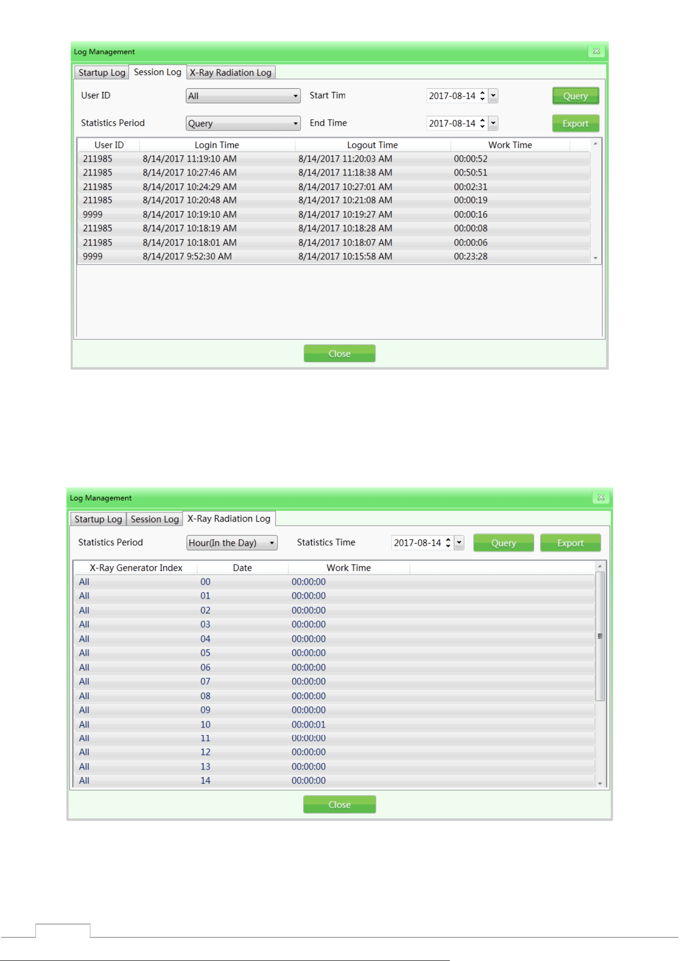
4.9.2 Session log
Specify the operator as a unit, get the working time data of each operator. The system will record the
start and end time of each operator's working period.
User ID: select a specific user by ID, or select all users.
Period Statistics: Same as the startup log. The work log can also be searched by day, week, month,
year. (Example: 2017-08-14, select all users and time in the period statistics, click "Query" to get the
results. See the figure below)
32
Fig. 4-26 Session Log
4.9.3 Radiation Emission Log
Concerns the operation of the radiation generator. Get records of the generator operation in a given
period to track the generator operating conditions. Select the required records from the query result
for export. The data export operation was described above..
Fig. 4-27 Radiation Emission Log
33
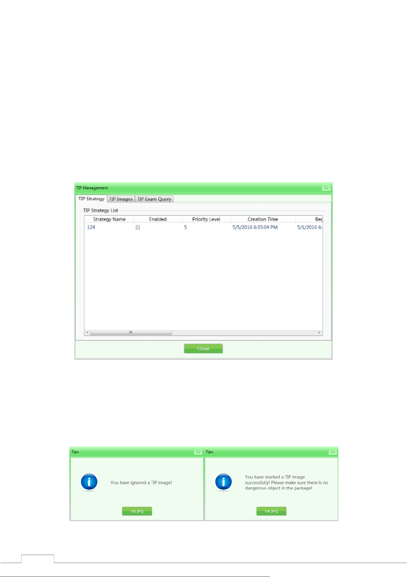
4.10 TIP(Threat Imitation Training)
Based on the relevant parameters set by the administrator, the system can automatically install the
images of the baggage containing dangerous goods into the images of the scanned items or install
dangerous goods of different types into the real images of the checked items. Like the normal images,
the TIP images will be automatically saved by the system. From the statistical report of the system, the
administrator can know the exact time of identification and omission of the installed image of the
dangerous goods by each operator. In this way, the administrator can track the training level and
efficiency of each operator.
TIP objectives:
1) Increase the vigilance of operators, prevent operators from losing detection skills due to the absence
of real dangerous objects during a long period of inspections.
2) Test the ability of operators in reading images of scanned objects.
TIP procedure:
Fig. 4-28 TIP interface
Log in as administrator, set the TIP strategy and default evaluation indicators. When the operator
detects a dangerous item, he should press the Stop key to stop the conveyor first, then press the Mark
key on the special keyboard or the P key on the normal keyboard, then the system will record the
operator's successful identification of the item. If the operator does not detect the TIP image of the
dangerous item, the system will immediately prompt "You missed the test image!" This error will also
be recorded. The TIP messages are shown in the figure.
Fig. 4-29 TIP messages
34
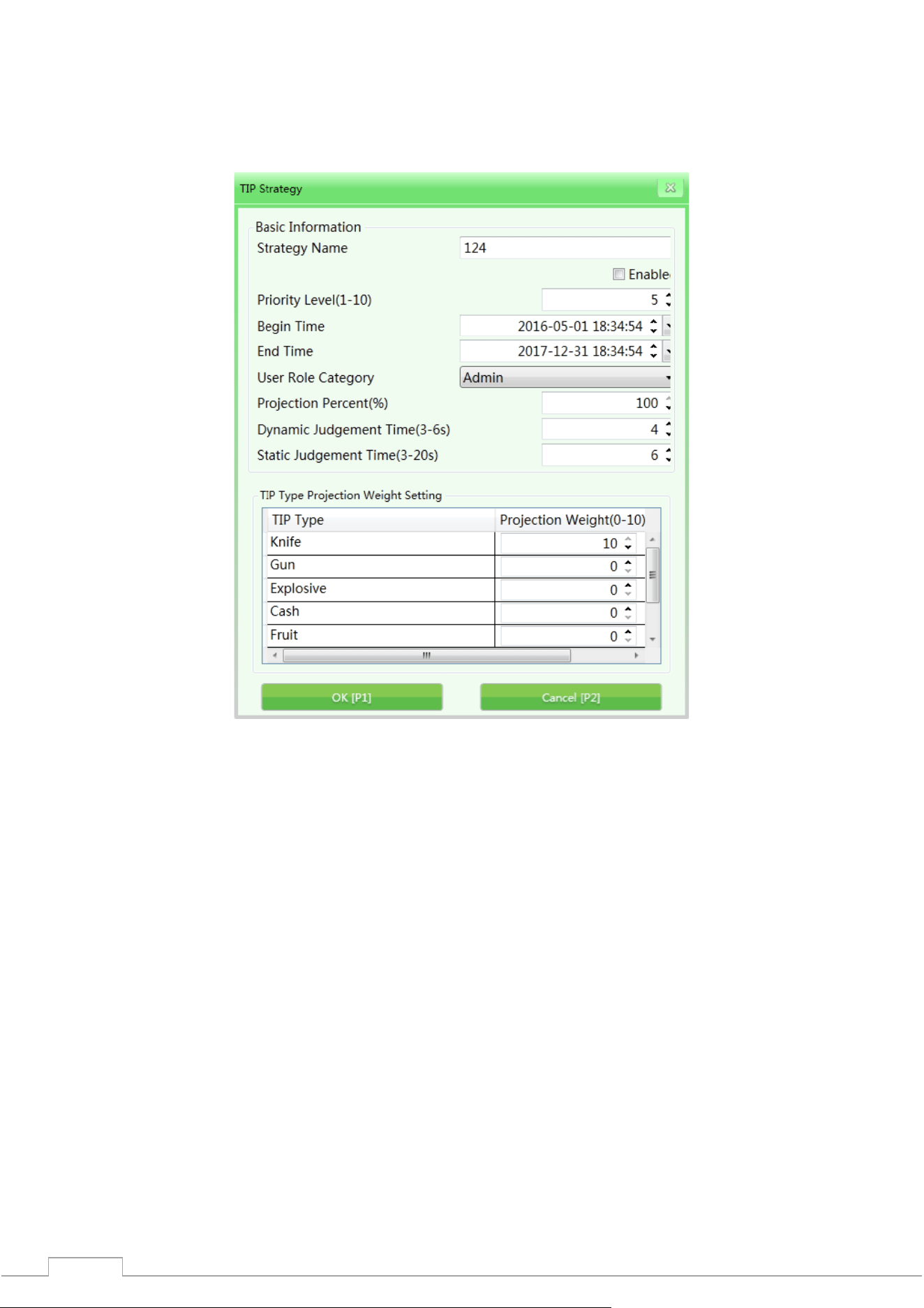
4.10.1 TIP strategy
The strategy generation function helps to set the basic TIP information and simulation aspects.
Basic TIP information: Strategy name, priority (1-10), start time, end time, user role, projection
percentage, non-stop inspection and static inspection. As shown in the figure:
Fig. 4-30 TIP strategy
Strategy Name: Assign a strategy name according to your own requirements;
Activation: Turn on/off the strategy, the "√" checkbox will mean that the strategy is enabled, the
following settings are available only when the strategy is enabled;
Priority: The administrator sets the priority levels (from 1 to 10, where 1 is the lowest priority). Items
with the highest priority will be rated higher;
User Category: Select the operator or administrator;
Simulation Projection Percentage: reflects the percentage value of the TIP image implementation.
Non-stop inspection: during the movement of images, if dangerous TIP elements have been
implemented, the period of time from the appearance to the disappearance of dangerous TIP elements
is defined as dynamic decision making (it is necessary to determine whether the elements are
dangerous within a short period of time) non-stop inspection;
Static inspection: when the images are not moving, if dangerous TIP elements have been
implemented, the period of time from the appearance to the disappearance of dangerous TIP elements
is defined as static decision making;
Imitation weight: It mainly distributes the weight to different types of TIP elements during use. The
main types of TIP elements are: "knife", "gun", "explosives", "cash", "fruit".
35
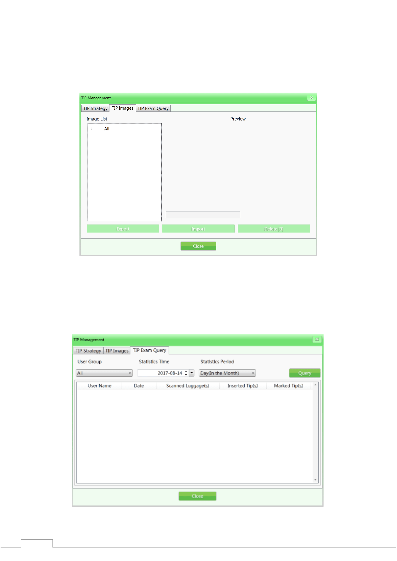
4.10.2 TIP Images
TIP images are listed in the gallery from which they will be embedded in the scanned items. Open the
image in the corresponding list to view the image.
Export: Users with rights can export TIP images as normal (export format - ZKX);
Import: Users with rights can import TIP images (only in ZKX format);
Delete: Users with rights can delete the selected TIP images by clicking "Delete".
Fig. 4-31 TIP Image Interface
4.10.3 TIP Examination
The function generates a query about the TIP element implementation process, information such as
“User Name”, “Date”, “Number of Scanned Baggage”, “Image Skip Time”, “Image Mark Time” and “TIP
Element Implementation Time” and allows you to export this information by clicking “Export”. The
result of TIP training will be displayed in the log.
Fig. 4-32 TIP examination
36
4.11 Training
After running the training function, the administrator can train operators to read images. The training
function is used to train and evaluate the ability of operators to detect dangerous and prohibited
elements. Training does not require running the conveyor and X-ray generator, the simulation of the
scanning process and displaying a series of images on the screen will be launched from among the
images saved by the administrator on the disk (IPC). The interface of the Training window has the
sections Setting Parameters on the left and Control Panel on the right.
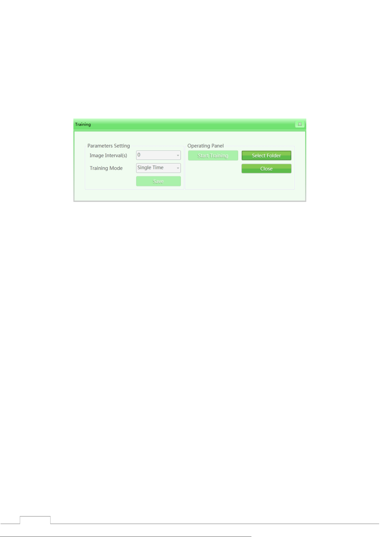
4.11.1 Setting parameters
Click “Training” in the main menu to open the training interface as shown in the figure.
Fig. 4-33 Setting up a workout
Interval between images: Set the interval between the displayed images. Select "Image Interval" with
the cursor and manually set the interval as "1", "2" or any desired interval. The intervals are possible
from 1 to 120 seconds.
Training mode: To set this function, you will need to select from the drop-down list: "Single", "Cycle",
"Random cycle" one of these modes. The operator can also set the training mode based on specific
needs.
4.11.2 Control Panel
By clicking the "Select Folder" button, you can manually specify the image gallery for training.
Please note: If the TIP function is activated, all training results will be recorded in the system.
The system will receive statistical data on the number of TIP trainings and TIP data of all users.
The administrator can check this data in the TIP request.
4.11.3 Training process
Step 1: Specify the folder with the luggage images.
Step 2: Set the parameters (the "Save" button to finish the installation).
Step 3: Click "Start Training". The training window can be closed, it can be restored (the icon that
shows the training process is running).
Step 4: Press any conveyor operation key (in the training mode, this action will not start the real
conveyor mechanism) or the image dragging button in the center, images will appear according to the
set parameters of the scanning process simulation.
Step 5: When suspicious items are detected, you need to press the "Stop" key and the "Mark" key on
the special keyboard to mark the image.
Step 6: If you want to finish the training, stop the conveyor and finish the training through the menu
or with the right mouse button.
37
4.12 System settings
The administrator has access to these functions: smart detection, keyboard settings, counter settings,
and others.
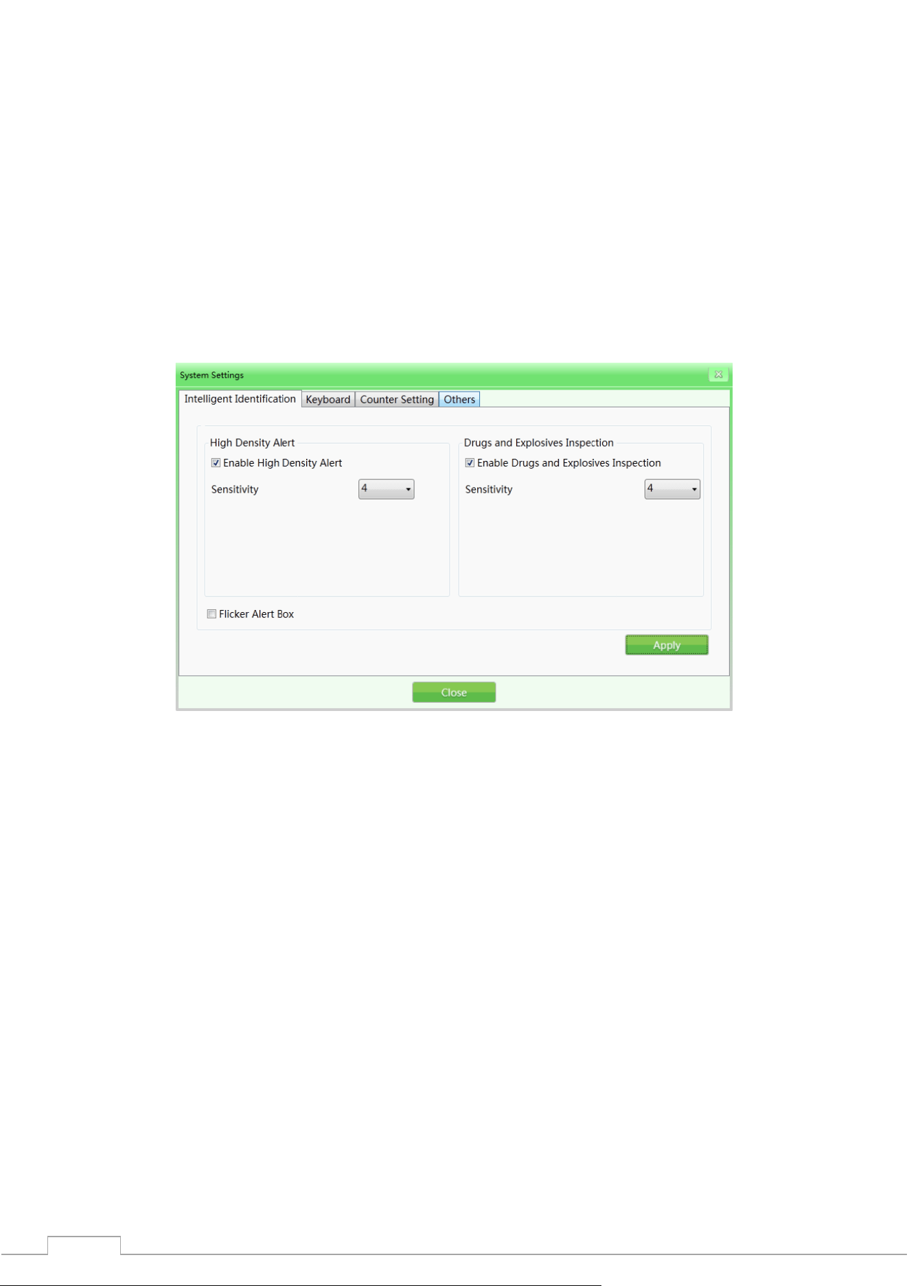
4.12.1 Intelligent Detection
This section is to set “High Density Warning” and “Drug and Explosives Screening”; the initialization
mode and sensitivity can be set separately (when “√” is activated, the “High Density Warning” warning
frame will be red, and the “Drug and Explosives Screening” warning frame will be purple. The sensitivity
can be further calibrated in the range of 1-5, where 5 is the highest sensitivity); when “Alert Frame
Blinking” is set, the frame will blink continuously to give an alarm signal.
Рис. 4-34 Интеллектуальное обнаружение
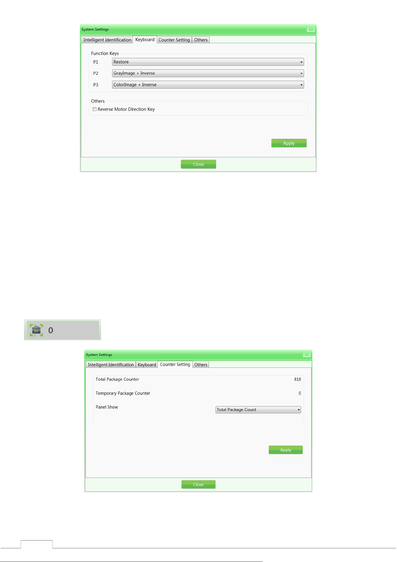
4.12.2 Keyboard
Function keys (shortcuts): When you need to set the image processing combination keys, click the
"Keyboard" tab in the system settings. Then select the corresponding image processing combination
function from the drop-down list based on your specific needs.
Shortcut Key Options
Color + Detail
B&W + Detail
Color + Invert
B&W + Invert
Color + Deep Scan
B&W + Deep Scan
Color + Surface Scan
B&W + Surface Scan
Toggle between B&W and Color
Restore
38
Fig. 4-35 Keyboard
Reverse Conveyor Movement: The standard installation of the equipment assumes that the conveyor
operates in the forward direction (the position of the marking - the direction from "inlet" to "outlet" is
the "forward direction"). The direction of the conveyor can be changed if the user requires it.
4.12.3 Setting up counters
If the operator needs to know and record the number of checked bags, he can check the "Baggage
Counter" indicator in the status panel or in the "Counter Settings" tab.
Total Baggage Counter: Shows the total number of checked bags. The readings cannot be reset.
Last Baggage Counter: Shows the number of checked bags for this session since the user logged in.
Please note: The operator can choose which indicator to display in the status panel. The choice
will immediately be reflected in the numerical indicator in the status panel.
Fig. 4-36 Counter settings
39
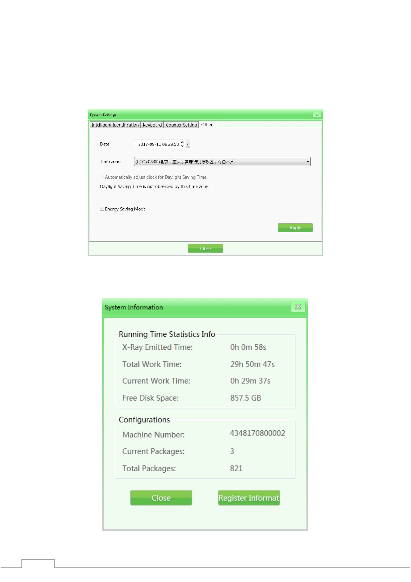
4.12.4 Other
Date: When you need to set the time and date, click "Date" to set the local time. Time Zone: You can set
the local time by these parameters.
Daylight Saving Time: You can set the daylight saving time parameters if applicable to your area. This
function is disabled by default.
Power Saving Mode: This function allows you to set the mode when the device's motor is automatically
turned off at the end of each single scan.
Fig. 4-37 Other
4.13 System information
Includes performance statistics and current configuration.
Fig. 4-38 System information

40
4.14 Exit and shutdown
Logout: Log out for an individual user. Power Off: Power off the device.
Please note: You need to turn the key to the “Off” position and wait until the green operation
indicator goes out, which means the system is completely turned off.

41
5 Maintenance
The introscope is a complex mechanical and electronic product. Therefore, the user should always be
guided by the principle of preventing malfunctions first. The user should not only familiarize himself
with the technical characteristics, software and operating procedure of the equipment, but also
effective daily, weekly, monthly, quarterly, annual maintenance, which is one of the important factors
that allows you to properly operate this equipment. This section is devoted to technical maintenance.
Matters requiring attention during maintenance
1) The equipment should be installed in a ventilated, dust-free and dry place. High temperatures, high
humidity and direct sunlight should be avoided.
2) Clean dust from the equipment before use.
3) If components, cables and connectors are loose or poorly connected, be sure to secure them.
4) Do not allow foreign objects or liquid to enter the equipment during maintenance to avoid electric
leakage or accidents.
5.1 Daily maintenance
Please note: Disconnect the equipment from the power source during cleaning.
5.1.1 External surface of the equipment
After a long time of operation, the outer surface of the equipment, control panel, display screen and
other parts may be covered with dust, stains, etc. In order to ensure the normal operation of the
equipment, the outer surface of the equipment should be cleaned regularly.
Wipe the following surfaces with a damp cloth:
1) The surface of the side walls and top cover of the equipment;
2) The protective walls on both sides of the conveyor, under the conveyor itself, etc.;
3) The surface of the conveyor belt;
4) The ventilation hole;
5) The surface of the control panel.
5.1.2 Display, photoelectric sensor and control panel
1) During daily use of the equipment, the surface of the display and fingerprint reader may be covered
with dust, traces that will affect the work of operators when reading images and identifying objects.
The display screen (in the off state) can be cleaned with a damp cloth and detergent.
2) When the photoelectric sensor is blocked or clamped, the radiation source will always be in a state
of emission. If the radiation indicator is on but no image appears on the screen, the cause of the
malfunction may be the hole section of the photoelectric sensor covered with dust or dirt. In this case,
you can use a brush to clean the hole, and then vacuum the part.
3) Open the back panel of the console with a triangular key and clean the dust clumps inside with a
brush or vacuum cleaner.
5.1.3 Photoelectric sensor
Start the equipment and place the luggage on the conveyor for inspection. If the item images are
clearly displayed on the screen, the photoelectric sensor is functioning normally.
If the item images are not displayed on the screen properly or the image is unstable, please clean the
hole area and the surface of the photoelectric sensor. Check again.
If the images are still not displayed normally, please contact the service organization for consultation
and repair.

42
5.1.4 Conveyor check
After a long period of operation, the conveyor belt may shift. Since the weight and position of the
objects are uneven, this may cause the conveyor belt to deviate from its center position. In this case,
consult a service organization for maintenance and repair.
5.1.5 Inspection of curtain at entrance and exit
If the gaps between the strips of lead curtain are too large or the curtain is damaged and falls off,
contact a maintenance service organization for advice and repair.
5.2 Monthly Check
5.2.1 Inspection of the Emergency Button
The emergency stop buttons at the entrance and exit of the equipment tunnel and the special
keyboard are extremely important safety features. When the equipment is inspecting items normally,
when the emergency stop button is pressed, the conveyor stops immediately and the X-ray indicator
lamp goes out, indicating that the emergency stop button works well. Later, restore the emergency
button and press the start button, the screen displays the status of "normal", then the emergency stop
button returns to its original position. If there is any abnormality in the emergency stop button, please
contact the service organization for consultation and repair.
5.2.2 Photoelectric sensor
Start the equipment and place the luggage on the conveyor for inspection. If the item images are
clearly displayed on the screen, the photoelectric sensor is functioning normally.
If the item images are not displayed on the screen properly or the image is unstable, please clean the
hole area and the surface of the photoelectric sensor. Check again.
If the images are still not displayed normally, please contact the service organization for consultation
and repair.
5.3 Quarterly inspection
5.3.1 Inside the equipment
The inside of the equipment is extremely important, as it includes the industrial personal computer
(IPC), electrical control panel, ventilation, detection box and other important parts. When cleaning the
inside daily, it is recommended to remove the dust clumps with a brush or vacuum cleaner.
1) Computer;
2) Electrical control panel (please remove the cover) and the device terminal.
3) Ventilation and switch;
4) Generator and detection box - only the surface, do not open the parts or fasteners.

43
5.3.2 Inspection of indicators
If the X-ray indicator (red) or power indicator (green) does not light while the equipment is operating,
contact your service provider for consultation and repair.
44
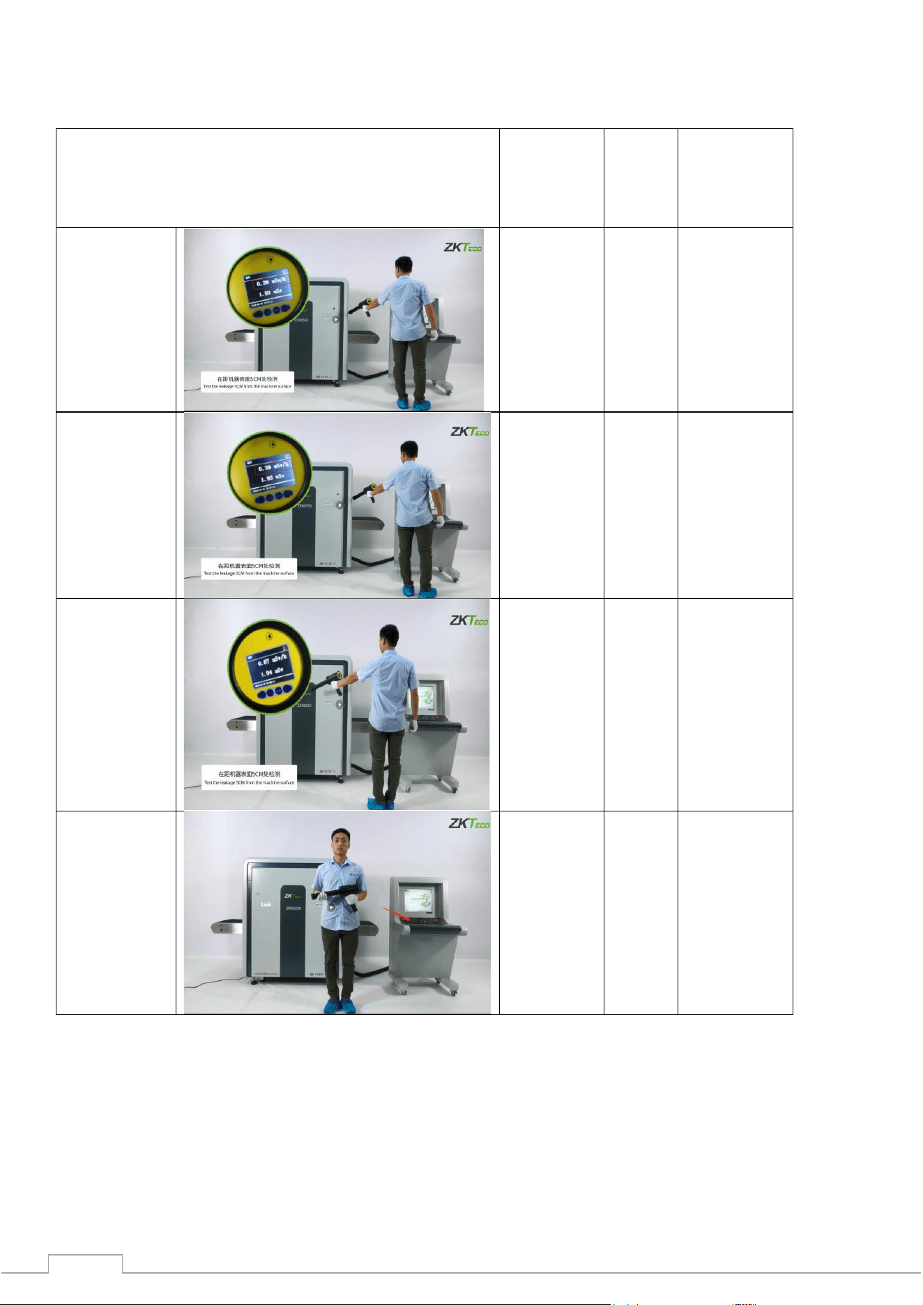
5.4 Annual inspection
At least once a year, check the radiation monitoring area: at a distance of 5 cm from the surface of the
device using an external radiation dosimeter.
Place of measurement
Measurements
should be
taken at a
distance from
the surface of
the device, cm
ZKTECO
test
result,
μGy
Single dose of
radiation during
device
inspection, μGy
At the
entrance to
the tunnel
5
0,39
<5
At the exit of
the tunnel
5
0,39
<5
On 2 side
surfaces
5
0,07
<5
Console
table
>5
0,07
<5
The results of the inspection should be recorded in the annual inspection log.
In case of problems with our equipment and hardware, please contact the service organization for
consultation and repair.
45
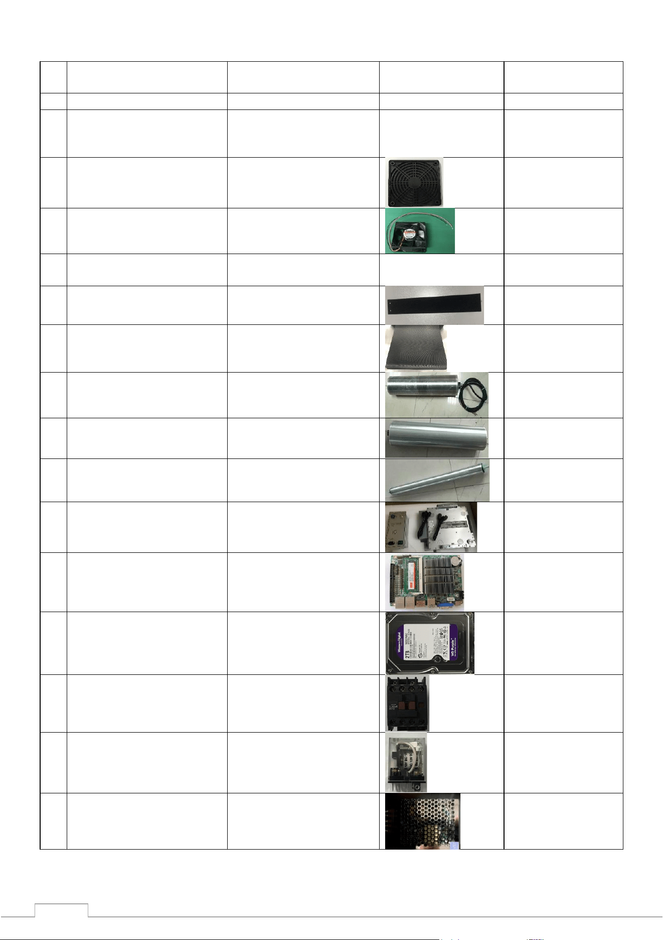
5.5 Recommended periods for scheduled preventive maintenance
Name of types of work
EPR Code for ordering
Photo
Recommended
timeframes
1
General cleaning
Twice a year
2
Cleaning the
photoelectric switch and
through hole
Twice a year
3
Replacing the Cooling Fan
Dust Shield
100003302
Twice a year
4
Replacing the cooling fan
100006967
Once every 10,000
hours.
5
Replacing the equipment
mounting screws
100009192
Once a year
6
Replacing a lead curtain
100007405
100007406
Once every 10,000
hours.
7
Conveyor Belt
Replacement
100007421
Once every 20,000
hours.
8
Replacing the support
roller
100006961
Once every 20,000
hours..
9
Replacing the driven
roller
100026287
Once every 20,000
hours..
10
Replacing the roller
motor
100003906
Once every 30,000
hours.
11
Replacing the X-ray
generator
100007260
Once every 30,000
hours.
12
IPC Motherboard
Replacement
100004042
Once every 20,000
hours.
13
IPC Hard Drive
Replacement
100021535
Once every 30,000
hours.
14
Contactor replacement
100004889
Once every 30,000
hours.
15
Replacing the relay
100004785
Once every 30,000
hours.
16
Replacing the pulse
power supply
100006765
Once every 30,000
hours.
46
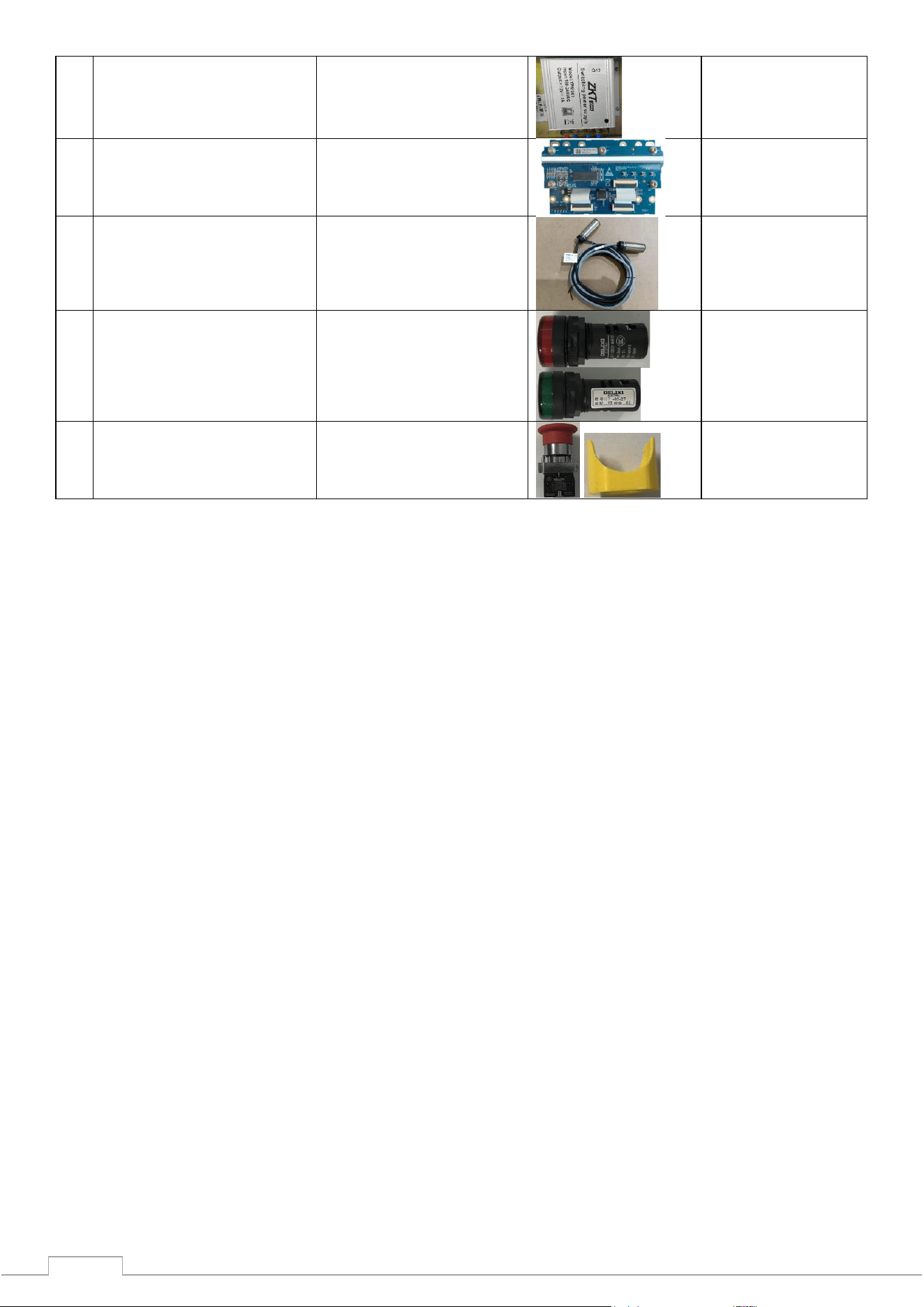
17
Replacing an air circuit
breaker
100006740
Once every 30,000
hours.
18
Replacing the detection
board/transmission
board
100010175
Once every 30,000
hours.
19
Replacing a photoelectric
switch
100001065
Once every 20,000
hours.
20
Replacing the indicator
100001067(red)
100001068(green)
Once every 30,000
hours.
21
Replacing the emergency
stop and stop button
100004890(button)
100003300( button
shell)
Once every 30,000
hours.

47
5.6 Storage conditions
1) Dismantling the equipment for transportation requires a set of actions that are the reverse of the
installation process of the equipment.
2) The equipment should be stored in clean and dry places, high temperature or humidity may cause
damage to the system parts. If the equipment is not used for a long time, it should be stored in special
packaging.
3) The equipment that needs to be stored for a long time should be packed and stored well in a clean,
dry and well-ventilated room where there should be no corrosive gases, and the relative humidity
should not exceed 80%.
4) According to the Regulations on Measures to Ensure the Safe Approval of Radioisotope and Beam
Devices of the People's Republic of China, this equipment belongs to Type III X-ray device. If
necessary, we suggest our customers to jointly supervise the work with the local competent
authorities for environmental supervision.
5) When the equipment needs to be disposed of, please contact the relevant service organization or
local competent authorities for clarification of the methods.

48
5.7 Troubleshooting
This section presents malfunctions that may occur, their causes and troubleshooting methods. If there
are problems that require a more serious solution, please contact the manufacturer for advice and
repair.
Maintenance of this equipment can only be performed with the appropriate components and spare
parts manufactured by our company and under specific conditions. In the event of machine failure due
to improper maintenance or equipment damage caused by the use of third-party spare parts not
provided by our company, our company will not bear any responsibility.
Error 1: The equipment does not start by pressing the button
1) If the equipment does not boot normally, please make sure the power cord plug is connected
correctly. First check the power supply voltage (the AC power supply voltage should be 200V-240V);
if there is no voltage or the voltage is abnormal (not within 200V-240V), please report it to the
responsible department to solve the problem until the power voltage returns to normal.
2) If the power voltage is normal but the equipment still does not boot, please check the connection
terminals 1 and 3 to see if there is 200V-240V voltage between the two terminals.
3) Check the switch on the equipment to see if it is off or not. Check the fuse, it may trip. If this
happens, please replace it.
4) If the connection at the control line jack (DB15) on the dedicated keyboard is loose, please
reconnect the control line and check the equipment whether it is booting normally.
Error 2: The conveyor does not move
1) If this happens, check if one of the "emergency stop" buttons (the emergency button on the
machine and the control panel respectively) is pressed; if so, turn the button clockwise and release the
button, then press the "Start" button to start the conveyor.
2) If the conveyor belt still does not work and the "Emergency Stop" status is displayed, check the two
"micro switches" on the equipment. When the two "side panels" on the equipment are secured, the
"micro switches" will operate. If
the "micro switches" do not operate due to the lack of any one of the "side panels", this will also cause
the "emergency stop" to operate. Secure the side panels, then press the "Start" button to start the
conveyor.
3) If the screen shows the status "Normal emergency stop", check the "anti-overload protector"
DZ108-20 of the conveyor to see if it is triggered (means overcurrent to the motor cylinder, which is
usually caused by excessive load (weight of luggage)). If this happens, reset it manually (press the
white button on the DZ108-20), and the conveyor should start normally.
Error 3: "Self-diagnostic system error" on the screen
1) Situation 1: The system displays the status of "Receiver Connection Error".
This is usually caused by a power failure on the "transmission board" (inside the small metal box next
to the "L-shaped shelf"). Check the power plug on the "transmission board", if it is loose or not
connected correctly, then reconnect the power plug. Check the transmission line plug to make sure it is
in good condition, reconnect this cable and the cable plug on the IPC board.
2) Situation 2: The system displays "Control Panel Communication Failure".
This is usually caused by a data line failure between the control panel and the industrial motherboard.
Check the data line plug (DB9 plug) of COM1 port on the industrial motherboard and the data line plug
(white plug of line 3) of J3 port on the control panel, if they are loose or not connected correctly,
reconnect the data line plugs at both ends.

49
Error 4: Keys on the special keyboard do not work
If the equipment boots normally with the key and start button on the dedicated keyboard, but the
conveyor control or image processing keys do not work, the failure is caused by a communication
problem with the data line on the COM2 port. Check the data line plug (DB9 connector) on the COM2
port of the industrial motherboard.
Error 5: Incorrect radiation
If the conveyor works normally but the radiation is not projected correctly, the screen will not display
images. Please check the ON / OFF XRAY_ON POWER indicators on the X-ray controller to make sure
the indicators light up normally (repeat the emergency stop process). Then press the emergency stop
button and check whether the connection of the INTERFACE and POWER connector is loose, if so,
please reconnect the control line and check whether the equipment boots up normally.
Error 6: Power failure
First, disconnect the power line, then check the switch. Turn the switch to the "Off" position. You should
wait for one minute, reconnect the power line, and then reboot the device as usual. At this point, the
computer will start Windows OS, the troubleshooting procedure or normal startup may begin.
If you start the login from troubleshooting, you must use the external keyboard of the PC to enter the
software interface.
In case of normal startup, go directly to the ZK software.
