
FIG. PART NO. DESCRIPTION OF PART NO. REQ.
1 02-02-1100 4mm Ball (1)
2 02-04-1516 Ball Bearing (1)
3 --------------- Spring Cover (1)
4 02-50-1640 Needle Bearing (1)
5 06-08-0017
3/16" Hex Drive Hub Bolt-RH Thread-1.125" long
(1)
6 --------------- Pivot Pin (2)
7 --------------- Rear Cam (1)
8 06-65-2995 Pin (1)
9 06-81-0065 10-32 x 2" Bolt (1)
10 06-82-3830 8-32 x 1/2" Csk Macine Screw (3)
11 06-82-3900 3/8" DG50 Thread Form Screw (2)
12 06-82-5316 8-32 x 1/2" Pan Hd. Taptite T-20 Screw (2)
13 06-82-5346 8-32 x 3/4" Pan Hd. Taptite T-20 Screw (5)
14 06-82-2620 8-32 x 1" Pan Hd. Taptite T-20 Screw (4)
15 06-82-7261 6-19 x 11/16" Pan Hd. Slt. Plast. T-15 (6)
16 06-82-7290 6-19 x 1-1/8" Pan Hd. Slt. Plast. T-15 (2)
17 14-09-0185 Crank Assembly-Right Hand Thread (1)
18 10-15-0955 Warning Label (1)
19 12-20-2620 Service Nameplate Kit (1)
20 02-04-2620 Ball Bearing (1)
21 16-01-2621 Service Armature with Fan (1)
22 18-01-2621 Service Field (1)
23 22-18-2625 Carbon Brush Assembly - Black (1)
24 22-18-2623 Carbon Brush Assembly - Red (1)
25 22-20-0860 Brush Tube (2)
26 22-32-0400 Brush Spring Clip (2)
27 --------------- Terminal Block Assembly (1)
28 23-66-0286 Switch/PCBA Assembly (1)
29 28-14-0210 Gearcase Assembly - Left (1)
30 28-14-0060 Gearcase Assembly - Right (1)
31 31-11-0105 Barrel Cam (1)
33 --------------- Handle - Left (1)
34 --------------- Handle - Right (1)
35 31-50-2620 Motor Cage (1)
36 32-05-0115 Spiral Bevel Gear (1)
37 34-40-0035 O-Ring (1)
38 34-60-3700 Retaining Ring (1)
39 38-50-0260 Spindle (1)
40 --------------- Torsion Spring (1)
FIG. PART NO. DESCRIPTION OF PART NO. REQ.
41 40-50-0595 Disc Spring (1)
42 40-50-0930 Compression Spring (1)
43 40-50-1090 Compression Spring (1)
44 40-50-8805 Extension Spring (1)
45 40-50-8840 Brush Spring (2)
46 42-40-0020 Spindle Pin Bushing (2)
47 42-40-0077 Spacer (1)
48 --------------- Front Cam (1)
51 43-06-0025 Metal Plate (1)
52 43-06-0030 Metal Plate (1)
53 43-56-0094 Orbit Slot (1)
55 --------------- Lock Pin (1)
56 44-66-0280 Bearing Retaining Plate (1)
57 44-66-0285 Retaining Plate (1)
58 --------------- Front Bushing Carrier (1)
60 --------------- Felt Seal (1)
61 45-06-0790 Seal (1)
62 45-12-0025 Gearcase Insulator (1)
63 45-16-0025 Shoe Assembly (1)
64 --------------- Sleeve (1)
65 45-24-0045 Shuttle Switch (1)
66 --------------- Bushing Cap (1)
67 --------------- Washer (1)
68 38-50-6490 Front Bushing Carrier Assembly (1)
69 14-46-1064 Blade Clamp Assembly (1)
71 44-66-5335 Bearing Retainer Plate (1)
72 02-04-0999 Ball Bearing (1)
73 45-28-0025 Grease Slinger (1)
74 32-60-0135 Pinion Gear (1)
75 42-55-2620 Accessory Carrying Case (1)
76 14-29-0390 Gear Assembly (1)
77 06-82-2395 M2.6 x 10mm Pan Hd. Plast. T-9 Screw (1)
78 31-44-0268 Handle Service Kit (1)
68
58 60
66 67
30
6
29
6
28
27
76
36 72
73 74
4x
2x
2x
6x
2x
5x
3x
Tab
Groove
Brush Tube
78
33
34
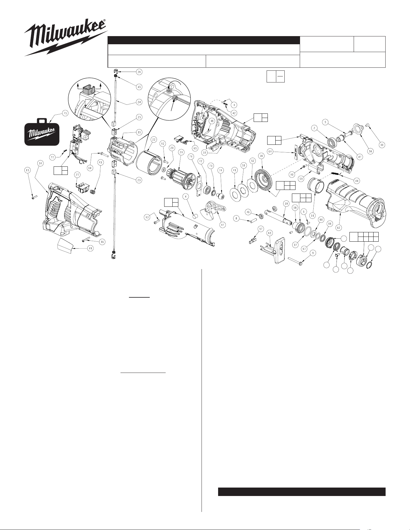
BULLETIN NO.
54-40-2625
SERVICE PARTS LIST
CATALOG NO. 2620-20
REVISED BULLETIN
SPECIFY CATALOG NO. AND SERIAL NO. WHEN ORDERING PARTS
M18™ Sawzall
®
STARTING
SERIAL NO.
DATE
Aug. 2022
WIRING INSTRUCTION
B58F
EXAMPLE:
Component Parts (Small #) Are Included
When Ordering The Assembly (Large #).
0
00
SEE PAGE TWO
Spindle (39)
to be assembled
with Lock Pin hole
oriented as shown.
Press Needle
Bearing (4)
ush to sub-ush
in Gearcase Half (30)
NOTE:
Bolt (5) is right hand thread.
SEE ADDITIONAL SERVICE NOTES ON FOLLOWING PAGES
54-40-2624
= Part number change from previous
service parts list.
NOTE: Pull both Brush Tubes
(25) back before re-
moving or installing
the Armature (21)
to prevent
damage to the
commutator.
IMPORTANT: Field (22) to be assembled
with tapper to back and square
groove to the top. Orient the
Motor Cage (35) with tap
to the top. Insert in groove.
MILWAUKEE TOOL
l
www.milwaukeetool.com
13135 W. Lisbon Road, Brookeld, Wisc. 53005
Drwg. 4
69
3
7
38 40
48 55 64
55
48
38
3
40
64
7
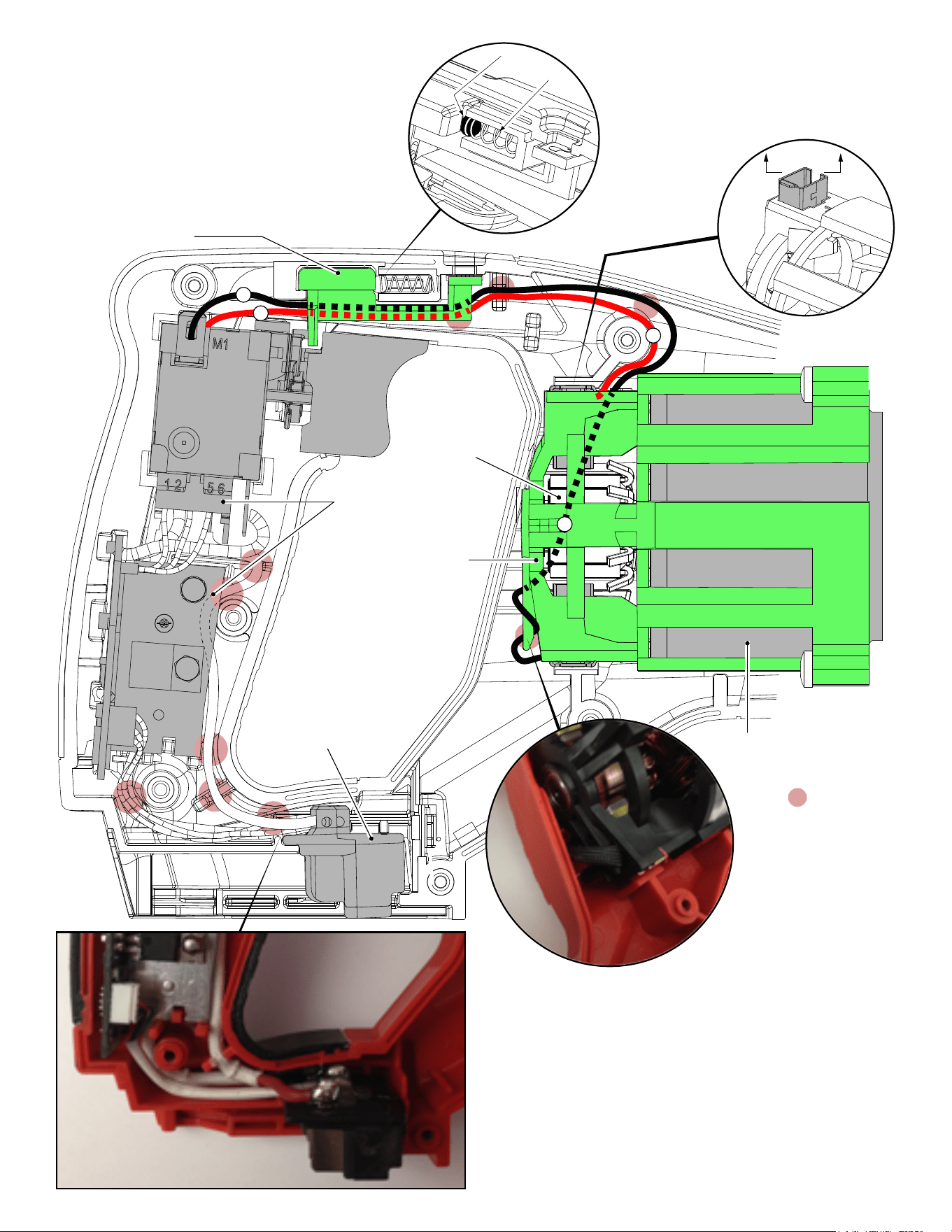
AS AN AID TO REASSEMBLY, TAKE
NOTICE OF WIRE ROUTING AND
POSITION IN WIRE GUIDES AND
TRAPS WHILE DISMANTLING TOOL.
BE CAREFUL AND AVOID PINCHING
WIRES BETWEEN HANDLE HALVES
WHEN ASSEMBLING.
Exercise caution when removing
the Right Handle Half (34), not
shown. The 4mm Steel Ball
(1) may be dislodged from
the Switch Shuttle (65) by
Spring (42).
Before installing or removing Armature,
to prevent damage to the brush tubes
or commutator, push / move Brush
Tubes (25) ush to inside brush tube
openings of Motor Cage (35) prior to
removing the Armature from Motor
Cage (35) /
Field (22).
= WIRE TRAPS
or GUIDES
1
42
2
2
1
1
Terminal Block
Assembly
Switch/PCBA Assembly
(Contains Terminal
Block Assembly)
Motor Cage
Field
Shuttle Switch
Armature
Commutator
Brush Tube
Before installing or removing Armature,
to prevent damage to the brush tubes
or commutator, push / move Brush
Tubes (25) ush to inside brush tube
openings of Motor Cage (35) prior to
removing the Armature from Motor
Cage (35) /
Field (22).
11
56
47
5
29
30
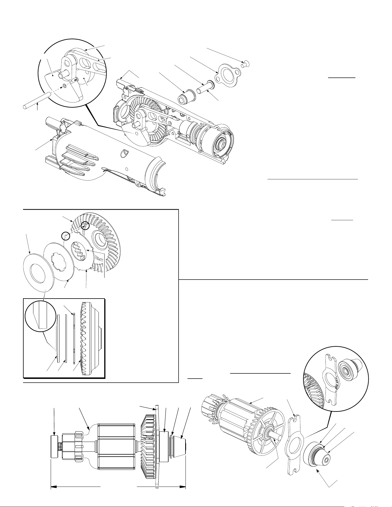
3/16” x 1-1/2”
steel pin
or the
equivalent
Right hand
thread
(2x)
17 Crank Assembly
Connecting Rod
Drive
Hub
Counter Balance
Remove Crank Assembly (17) from Left Gearcase Assembly (29) by separating / removing Right Hous-
ing Half (30). Remove Bearing Retaining Plate Screws (11) and Bearing Plate (56) from Left Gearcase
Assembly (29). Place a 3/16” diameter x 1-1/2” long steel rod down through the opening in the Counter
Balance until it bottoms out through the 3/16” hole in the Drive Hub.
Next place a 3/16 hex key into Drive Hub Bolt (5) and turn
Drive Hub Bolt slowly in a counter-clockwise direction until
3/16” steel pin rest against Connecting Rod. 3/16”
hex key can now be turned counter-clockwise to
loosen and remove RH Drive Hub Bolt (5).
When reinstalling / tightening Right Hand
Drive Hub Bolt (5):
1. Place lubricated Gear Assembly (36, 41, 51 &
52) into Left Gearcase Assembly (29). See
Figure 4 on page 3 for assembly instructions
with correct Disc/Plate orientation).
2. Position assembled Spindle/Crank Assembly
(17, 39, 8, 46, 53, 68, 37 & 69) into Left
Gearcase. (Spindle components should be
pre-lubricated with a light coating of grease
prior to reassembly). It is also benecial to have
the Barrel Cam (31) and Extension Spring (44)
installed in Left Gearcase (29). Once the
Spindle/Crank Assembly is in the Left
Gearcase, position/seat the Front Bushing Car
rier (58) over Pivot Pin (6) that's pressed into
Left Gearcase Assembly. Secure Orbit Slot (53)
to the Left Gearcase Assembly using the three
Screws (10) removed in disassembly.
3. Turn Crankshaft/Spindle Assembly by hand, applying a downward pressure until
the splines located on the bottom of the Crank Assembly Drive Hub drop down
and interlock with the splined notches in the I.D. of Metal Plate (51). Once the
two pieces are interlocked together, hold the assembly down tight and turn
Gearcase Assembly (29) over to enable the Right Handed Drive Bolt (5) and
Spacer (47) to be slid through Ball Bearing (2). (Before installing Drive Hub Bolt
(5) be sure to apply Blue Loctite® to bolt threads). Place the 3/16" x 1-1/2" long
steel rod used in disassembly, back through the Counter Balance of Crankshaft
Assembly (17) and slowly turn Right Handed Drive Bolt (5) in a clockwise
direction until 3/16" long steel rod rests against Connecting Rod. Before
tightening Drive Hub Bolt (5), make sure the raised notches located on the O.D.
of Metal Plate (52) are engaged with corresponding recess in Spiral Bevel Gear
(36), see Figure 4. Using an inch pound torque wrench and a 3/16" hex key,
torque Drive Hub Bolt (5) to 210 in./lbs. or bolt can be tightened using a foot
pound torque wrench to 17-18 ft./lbs.
IMPORTANT:
Concave side of Disc Spring
(41) must face toward Metal
Plates (51,52) and Gear (36).
Be sure that notches on Metal
Plate (52) engage with cor-
responding recesses in Spiral
Gear (36).
NOTE:
Do not wash Crank Assembly
(17) in solvent solutions; wipe
o only using a clean, dry lint
free Cloth.
21
71
73
Apply a thin coat
of lightweight oil
to armature shaft.
72
74
NOTE:
To achieve the proper press dimension shown below, pre-assemble / press
together Ball Bearing (72), Grease Slinger (73) and Pinion Gear (74) prior to
assembly onto the Armature (21).
Place a thin coat of lightweight oil onto the fan end of the armature shaft to aid
in the pressing of the pre-assembled parts. Prior to assembly with the Armature,
be sure that the Bearing Plate Retainer (71) is positioned
with the side reading 'fan side' facing the fan as shown.
IMPORTANT:
When reassembling parts (71, 72, 73 & 74) onto
the Armature (21), use a conventional arbor
press. Utilizing a hydrolic press IS NOT
recommended!
Pre-assemble
these three parts
4.705”±0.006”
(119.5±0.15)
71 72 73 7420 21
36
51
52
41
I.D.
Splined
Notches
41 51 36
52
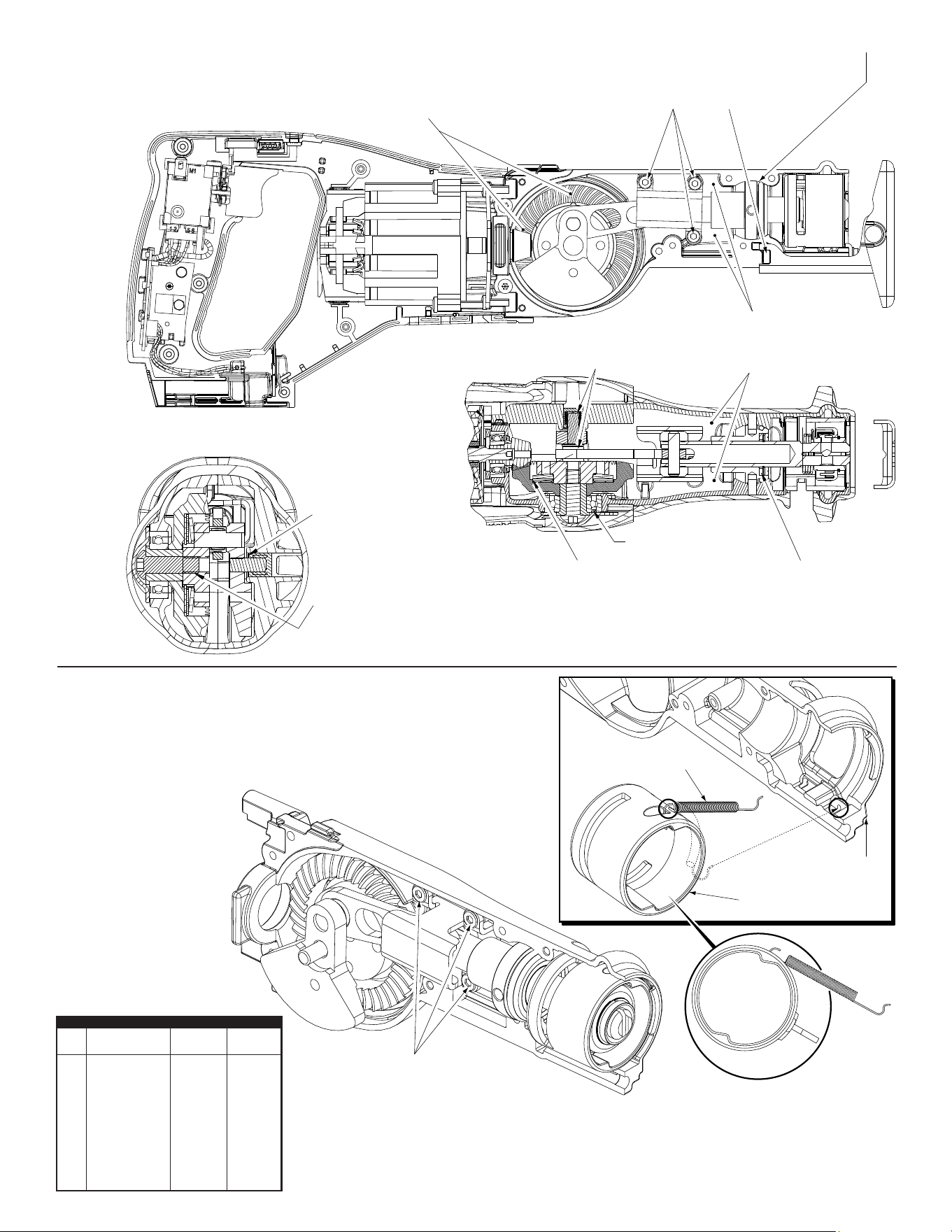
As an aid to install Extension Spring (44), assemble
gearcase components as shown. Loosen but do not
remove the three Orbit Slot Screws (10). This will allow
for the front end assembly, including the Barrel Cam (31)
to pivot away from the Left Gearcase (29). There should
be enough room to attach the Extension Spring to the
top recess area in the Barrel Cam and small hole in the
bottom front of the Left Gearcase. Spring should wrap
around the side of the Barrel Cam and rest inside
channel in the gearcase half. Retighten
the three Orbit Slot Screws.
Orbit Slot
Screws (10)
Left Gearcase
Assembly (29)
Barrel
Cam (31)
Extension Spring (44)
Apply Green Loctite® 620 or equivalent to
threads of Orbit Slot Screws (3 & 10) and
inside threads of Retaining
Plate (57).
Coat front bushing pocket area in both Gearcase Halves (29,30)
with a light film of Type ‘B’ Grease prior to assembly.
Apply Type 'L' Grease, No. 49-08-4230 to
the inside of Needle Bearings (3,4) prior
to assembly.
Distribute 1 oz. of Type 'L' Grease
on top of Spiral Bevel Gear (36) and
at Gear/Connection Rod (59) interface.
Apply Type 'L' Grease to all
rubbing surfaces in clutch:
Disc Spring (41) and
Metal Plates (51,52).
Distribute 3/4 oz. of Type 'B' Grease,
No. 49-08-2000 in the Left and Right
Gearcase halves (29,30), by Front
Bushing (58) around the Spindle (39).
Prior to assembly, saturate
the Felt Seal (60) with a
lightweight oil.
Bearing seal direction
Apply Green Loctite® 620
or equivalent to threads of
LH Drive Hub Bolt (5).
Press Needle Bearing (4)
.030” minimum subflush.
TORQUE SPECIFICATIONS
Max. Min.
Fig. Part No. (In-Lbs) (In-Lbs)
5 06-08-0015 190 160
9 06-81-0065 30 25
10 06-82-3830 35 25
11 06-82-3900 40 30
12 06-82-5316 35 25
13 06-82-5346 35 25
14 06-82-2620 15 10
15 06-82-7261 20 10
16 06-82-7290 20 10

REMOVING THE STEEL QUIK-LOK
®
BLADE CLAMP - VERSION 1
• Remove external retaining ring (38) and pull front cam (48) off.
• Pull lock pin (55) out and remove remainder of parts and discard.
REASSEMBLY OF THE STEEL QUIK-LOK
®
BLADE CLAMP
• Coat new lock pin with powdered graphite.
• Hold tool in a vertical position.
• Place spring cover onto spindle.
• Slide torsion spring (40) onto spindle with spring leg on hole side of spindle.
• Slide sleeve (64) onto spindle aligning hole on sleeve with hole in spindle.
• Slide rear cam over sleeve until it bottoms on sleeve shoulder, ensure spring leg
inserts into groove of cam.
• Rotate rear cam in the direction of the arrows located on spring cover until there is
clearance for lock pin (55) to be inserted into sleeve/spindle holes. Insert lock pin.
• Align front cam (48) inner ribs with rear cam outer slots and slide front cam onto sleeve
until it bottoms. Retaining ring groove should be completely visible.
• Attach retaining ring (38) by separating coils, inserting end of ring into groove. Wind remainder of ring into groove. Ensure ring is seated in groove.
• Blade clamp should rotate freely. During normal usage, debris may not allow blade clamp to rotate freely. The use of spray lubricant can
help free blade clamp. In extreme conditions, follow these instructions to remove, clean and reassemble blade clamp.
Leg
Spindle (39)
Spring Cover (3)
Torsion Spring (40)
Sleeve (64)
Rear Cam (7)
Front Cam (48)
Retaining
Ring (38)
Lock Pin (55)
Hole/Groove