Service for Milwaukee Tool ONE KEY Products
can only be performed at this
Milwaukee factory Central Repair Center:
MILWAUKEE TOOL Central Repair
1401 Sycamore Avenue
l
Greenwood, MS 38930-7277
Please send your tool directly to this location for service.
Or
Via e-Service at: www.milwaukeetool.com/e-service
questions, please call 1.800.SAWDUST (1.800.729.3878)
Or
Return it to a MILWAUKEE factory Service Center location, freight prepaid and insured.
A copy of the proof of purchase should be included with the return product.
If you have questions please contact Milwaukee Product Service at:
Product Technical Support via phone at: 262.783.8642
Or
Via email at: METProductSupport @milwaukeetool.com
Disassembly is not recommended and could void the warranty.
2721-20
M18™ FUEL™ ONE KEY SAWZALL
®
Oct. 2019
54-00-2721
REVISED BULLETIN
SERVICE PARTS LIST
BULLETIN NO.
WIRING INSTRUCTION
DATE
CATALOG NO.
SPECIFY CATALOG NO. AND SERIAL NO. WHEN ORDERING PARTS
SERIAL
NUMBER
Drwg. 3
H31A & H31B
SERVICE INSTRUCTIONS PAGE 3
EXTERNAL SERVICE PARTS PAGE 2
60
59
58
57
(2x)
13
15
(2x)
14
36
(2x)
44
16 1 12
4
5
7
10
6
8
9
103
4 5 6 7
8 9 10
108
36
112
59
60
114
EXTERNAL SERVICE PARTS PAGE 2
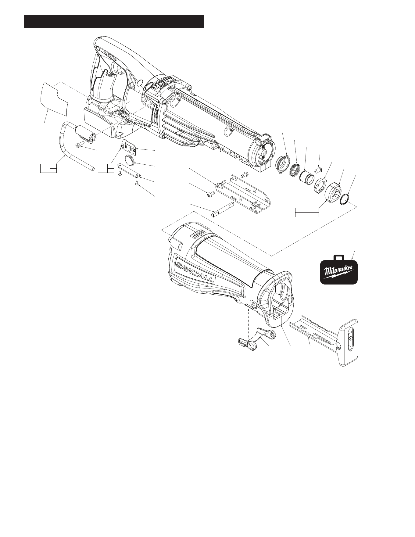
FIG. PART NO. DESCRIPTION OF PART NO. REQ.
1 45-12-0040 Gearcase Insulator 1
4 34-60-3700 Retaining Ring 1
5 --------------- Front Cam 1
6 --------------- Sleeve 1
7 --------------- Rear Cam 1
8 --------------- Torsion Spring 1
9 --------------- Spring Cover 1
10 --------------- Lock Pin 1
12 45-16-0135 Shoe Assembly 1
13 44-86-0225 Shoe Retainer 1
14 44-60-1635 Shoe Pin 1
15 06-82-7253 8-32 x 3/8" Pan Hd. Taptite T-20 Screw 2
36 05-78-0910 M4 x 12mm Fillister Hd. Screw 2
44 12-20-0078 Service Nameplate 1
57 05-81-1100 M2.6 x 6mm Flat Head Phillips Screw 2
58 31-15-0013 Coin Cell Cover 1
59 50-11-0020 3V Coin Cell Battery (CR 2032) 1
103 14-46-1064 Quik-Lok
®
Blade Clamp Kit 1
108 14-36-0340 Rafter Hook Assembly 1
112 22-09-2757 Bluetooth PCBA with Battery 1
114 42-55-0019 Carrying Case 1
See page three for service instructions
on removing and installing the Steel
Quik-Lok
®
Blade Clamp Assy. (103).
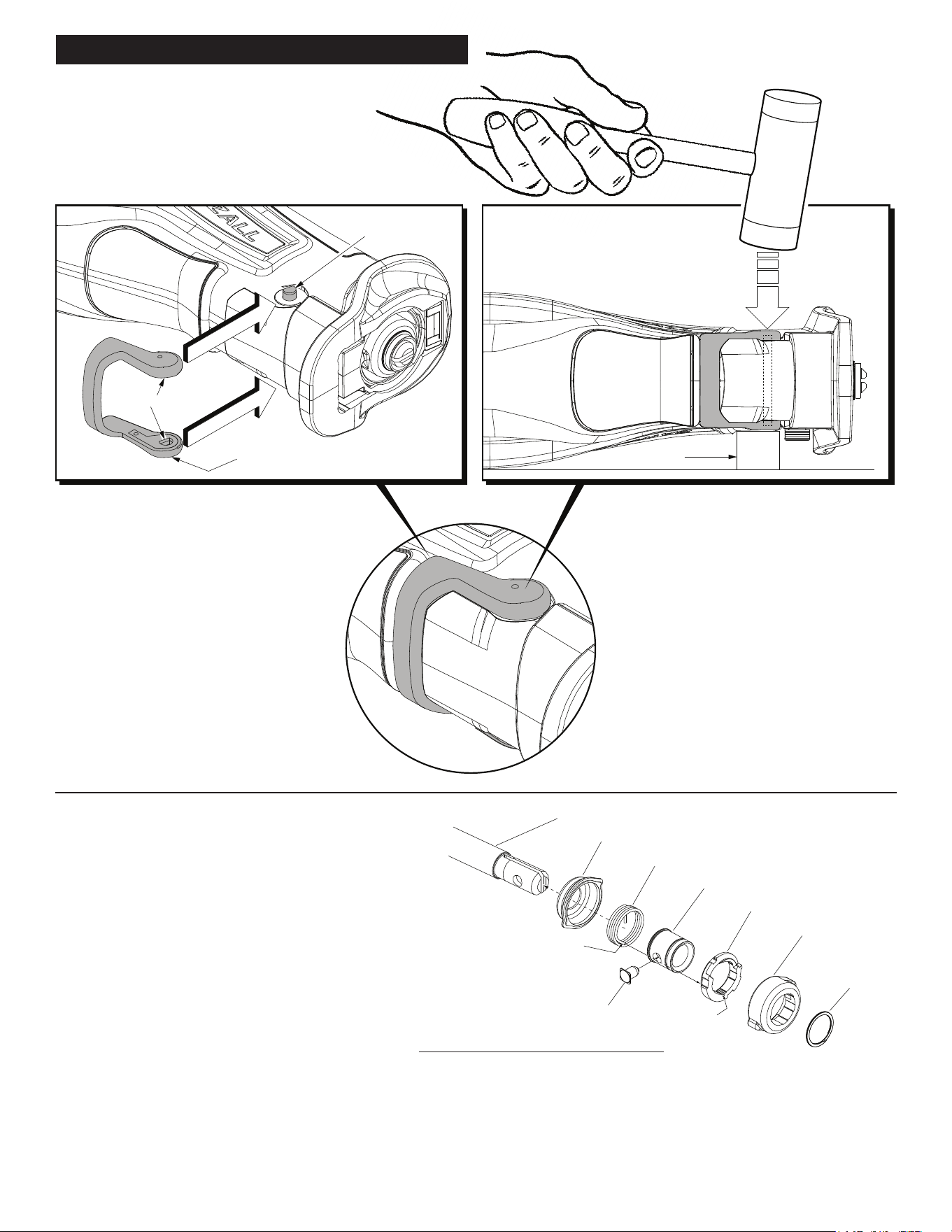
See page three for service instructions
to properly install the Shoe Release
Lever (16) onto Shoe Pin (14).
Shoe Pin
#14
Shoe Release Lever #16
Block
To properly install the Shoe Release Lever
#16 onto the Shoe Pin #14 do the following:
Insert the shoe pin through the hole in the
gearcase insulator. Center the shoe pin with
equal amounts of the pin protruding from each
side of the tool.
Rotate the shoe pin so the flats of the pin will
align with the flats in the shoe release lever
cavities.
The shoe release lever is stiff but flexible. Place
the shoe release lever over the gearcase
insulator. Lift one end of the shoe release lever
onto the shoe pin (with flats aligned) and press
into place.
Pull the other end of the shoe release lever over
the other side of the pin and press in place.
Flats
(both sides)
Place the tool on its side on a hard flat surface.
Place a small wood block approximately 1-1/8”
thick under the tool, between the hard surface
and the shoe release lever, directly beneath the
pin.
With a rubber mallet, strike the shoe release
lever several times to completely seat the lever
onto the pin and to asure that the pin is properly
centered within the gearcase.
REMOVING THE STEEL QUIK-LOK
®
BLADE CLAMP - VERSION 1
• Removeexternalretainingring(4)andpullfrontcam(5)o.
• Pull lock pin (10) out and remove remainder of parts and discard.
REASSEMBLY OF THE STEEL QUIK-LOK
®
BLADE CLAMP
• Coat new lock pin with powdered graphite.
• Hold tool in a vertical position.
• Place spring cover onto spindle.
• Slide torsion spring (8) onto spindle with spring leg on hole side of spindle.
• Slide sleeve (6) onto spindle aligning hole on sleeve with hole in spindle.
• Slide rear cam over sleeve until it bottoms on sleeve shoulder, ensure spring leg inserts into groove of cam.
• Rotate rear cam in the direction of the arrows located on spring cover until there is clearance for lock pin (10) to be
inserted into sleeve/spindle holes. Insert lock pin.
• Align front cam (5) inner ribs with rear cam outer slots and slide front cam onto sleeve until it bottoms.
Retaining ring groove should be completely visible.
• Attach retaining ring (4) by separating coils and inserting end of ring into groove, then wind remainder of ring into groove.
Ensure ring is seated in groove.
• Blade clamp should rotate freely. During normal usage, debris may not allow blade clamp to rotate freely. The use of spray lubricant can
help free blade clamp. In extreme conditions, follow these instructions to remove, clean and reassemble blade clamp.
SERVICE INSTRUCTIONS PAGE 3
Leg of Torsion Spring
is captured in groove
of Rear Cam
Groove
Spindle (11)
Spring Cover (9)
Torsion Spring (8)
Sleeve (6)
Rear Cam (7)
Front Cam (5)
External
Retaining
Ring (4)
Lock Pin (10)