46 47 48
64 77
18
27
81
16
2
3
5
6
4
8
7
17
60
62
34
88
19
20
48
49(2x)
47(2x)
51
52
57
64
63
45
43
42
40
41
44
24
(2x)
28
29
(6x)
21
23
1
22
47(5x)
46
59
58
32
31
30
26
(4x)
25
9
10
26
(2x)
75
74
50
(4x)
72
73
70
76
71
82
40 41 42
43 44 45
87
27 28
34
84
51 57
59
83
85
2 3 4 5
6 7 8
91
80
60
89
47 49
52 63
90
70
76
86
27 71
72
MILWAUKEE ELECTRIC TOOL CORPORATION
13135 W. Lisbon Road, Brookeld, WI 53005
Drwg. 3
BULLETIN NO.
54-40-2701
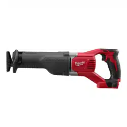
SERVICE PARTS LIST
FIG. PART NO. DESCRIPTION OF PART NO. REQ.
1 45-12-0040 Gearcase Insulator 1
2 --------------- Spring Cover 1
3 --------------- Torsion Spring 1
4 --------------- Rear Cam 1
5 --------------- Lock Pin 1
6 --------------- Sleeve 1
7 34-60-3700 Retaining Ring 1
8 --------------- Front Cam 1
9 31-11-0105 Barrel Cam 1
10 40-50-8805 Extension Spring 1
16 45-06-0230 'H' Seal 1
17 45-16-0135 Shoe Assembly 1
18 38-50-0076 Spindle 1
19 42-40-2052 Rollers 2
20 06-65-0145 Pin - Connecting Rod 1
21 44-86-0225 Shoe Retainer 1
22 31-15-2015 Shoe Release Lever 1
23 44-60-1635 Shoe Pin 1
24 06-82-7253 8-32 x 3/8" Pan Hd. Taptite T-20 Screw 2
25 43-56-0045 Orbit Slot 1
26 06-82-8890 1/2-DG50 Thread Form T-25 Screw 6
27 06-65-0135 Pivot Pin 2
28 --------------- Gearcase Halve - Right 1
29 06-82-5411 10-24 x 0.625 Pan Hd. Taptite T-25 Scr. 6
30 32-05-1010 Bevel Gear 1
31 43-06-0025 Metal Plate 1
32 40-50-0595 Disc Spring 1
34 02-50-1640 Needle Bearing 1
40 05-78-0910 M4 x 12mm Fillister Hd. Screw 2
41 --------------- Rafter Hook Mounting Bracket 1
42 --------------- Rafter Hook Spring 1
43 --------------- Rafter Hook Bushing 1
44 --------------- Spring Pin 1
45 --------------- Rafter Hook 1
46 06-82-7240 6-19 x 1/2" Pan Hd. Plast. T-15 Screw 1
47 06-82-7261 6-19 x 11/16" Pan Hd. Plast. T-15 Scr. 7
48 --------------- Handle Halve - Right 1
49 06-82-7290 6-19 x 1-1/8" Pan Hd. Plast. T-15 Scr. 2
50 05-88-8309 M5 x 35mm Pan Hd. Taptite T-20 Screw 4
51 --------------- Control Board/Terminal Connector Block 1
CATALOG NO. 2720-20
REVISED BULLETIN
54-40-2700
SPECIFY CATALOG NO. AND SERIAL NO. WHEN ORDERING PARTS
M18 FUEL™ SAWZALL
®
Reciprocating Saw
STARTING
SERIAL NO.
DATE
Feb. 2017
WIRING INSTRUCTION
F39B
EXAMPLE:
Component Parts (Small #) Are Included
When Ordering The Assembly (Large #).
0
00
SEE PAGE 5
FIG. PART NO. DESCRIPTION OF PART NO. REQ.
52 --------------- Motor Cage - Right 1
57 --------------- Stator/PCBA Assembly 1
58 42-42-0195 Lockoff Shuttle 1
59 --------------- On-Off Switch 1
60 02-04-0645 Ball Bearing 1
62 06-82-5324 10-24 x 1/2" Pan Hd. Tapt. T-25 Screw 2
63 --------------- Motor Cage - Left 1
64 --------------- Handle Halve - Left 1
70 --------------- LED Tray 1
71 --------------- Gearcase Halve - Left (w/ locating pins) 1
72 02-04-1516 Ball Bearing 1
73 42-40-0076 Spacer 1
74 06-08-0019 Drive Hub Bolt (Left Hand Thread) 1
75 44-66-0280 Bearing Retaining Plate 1
76 --------------- LED Assembly 1
77 12-20-2669 Service Nameplate (Not Shown) 1
80 16-01-0110 Rotor Assembly 1
81 14-86-0105 Front Bushing Assembly 1
82 14-36-0340 Rafter Hook Assembly 1
83 14-34-0260 Handle Halve Assembly 1
84 14-20-0325 Electronics Assembly 1
85 14-46-1064 Quik-Lok
®
Blade Clamp Kit 1
86 14-30-0185 Gearcase Halve - Left Assembly 1
87 14-30-0180 Gearcase Halve - Right Assembly 1
88 14-09-1000 Crankshaft Assembly 1
89 14-50-0215 Motor Cage Assembly 1
90 22-09-2600 LED and Tray Assembly 1
91 42-55-2720 Carrying Case 1
92 23-94-0082 High Voltage Wire (See page 5) 1
93 22-56-0150 Closed End Connector (See page 5) 1
See page 4 for
special service
notes
= Part number change from previous
service parts list.
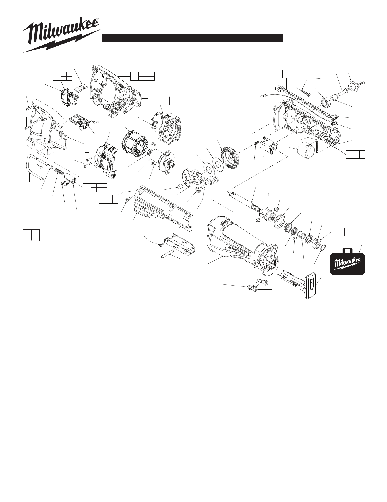
LUBRICATION: Type ‘L’ Grease
No. 49-08-4175 (16 oz. tub)
Place 30g ±3g (approx. 1 ounce) on top of gear (30) and pinion gear of rotor
assembly (80), being sure to cover the middle of the gear and all teeth.
Place 15g ±3g (approx. .5 ounce) to the area where the gear (30) and the
connecting rod of crank shaft assembly (88) interface.
Coat both sides of the metal clutch plate (31).
Lightly coat both pivot pins (27) where connections go into holes of front
bushing assembly (81).
Lightly coat both ends of pin (20) prior to installing rollers (19).
Ball bearing (3)
to be pressed
to gearcase stop
with seal to the
outside.
Press needle
bearing (5) flush to
subflush .005”.
BACK VIEW
Gearcase
stop
Ball bearing (72)
Seal
Retaining Plate (75)
Approximately .020-.025
above gearcase bore
Pinion Gear of
Rotor Assembly
#80
NOTE: Counter Weight of
Crankshaft Assembly #88
has been removed for clarity
(to reveal pinion gear)
Connecting Rod
of Crankshaft
Assembly #88
Bevel Gear #30
NOTE: Orbit Slot #25 has
been removed from this view
for clarity (to reveal Connecting
Rod Pin #20 and Rollers #19)
Connecting
Rod Pin #20
Rollers #19
30
88
32
31
30
20
19
Concave side of disc
spring (32) must face
toward metal plate (31)
and bevel gear (30).
32
31
4
3
2
1
When securing the orbit
slot (25), tighten screws
(26) in the order shown.
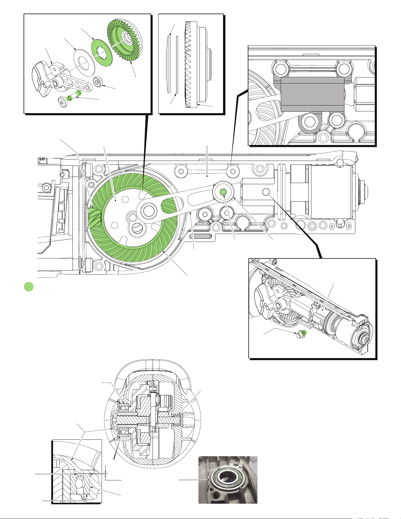
Pivot Pin #27 (2x)
Used on both sides
of Front Bushing
Assembly #81
Front Bushing
Assembly #81
Gearcase - Right (28)
Crankshaft
Assembly (88)
Bearing Retaining Plate (75)
Drive Hub Bolt (74)
Left hand thread
Screws (26)
Gearcase - Left (71)
Do not wash crankshaft
assembly (88) in solvent solutions;
Wipe off only using clean, dry, lint-free cloth.
Removing Crankshaft Assembly (88) from Left Gearcase (71)
Remove, crankshaft assembly (88) from left gearcase (71) by separating / removing right
housing half (28). Remove bearing retaining plate screws (26) and bearing plate (75) from left
gearcase (71). Place a 3/16” diameter x 1-1/2” long steel rod through the holes found in the
counter balance and drive hub of crankshaft assembly (88) until it bottoms out.
Next place a 3/16” hex key into drive hub bolt (74) and turn drive hub bolt slowly in a clockwise
direction until 3/16” steel pin rest against crankshaft assembly connecting rod. The 3/16” hex
key can now be forcibly turned clockwise to loosen and remove drive hub bolt (74).
Reinstalling Crankshaft Assembly (88) into Left Gearcase (71)
To reinstall drive hub bolt (74) to crankshaft assembly (88) apply Blue Loctite
®
(44-20-0090) to threads of drive
hub bolt (74) and insert through spacer (73) aligning threads of drive hub bolt (74) with internal threads of crank-
shaft assembly hub. Use a 3 /16” hex key to turn the drive hub bolt (74) slowly in a counter clockwise direction
until 3/16” steel pin rest against crankshaft assembly connecting rod (See ‘Removing Crankshaft Assembly’
instructions above). Using an inch pound torque wrench and a 3/16” hex key, torque drive hub bolt (74) to
210-240 in. lbs. or bolt can be tightened using a ft. lbs. torque wrench to 17-20 ft. lbs.
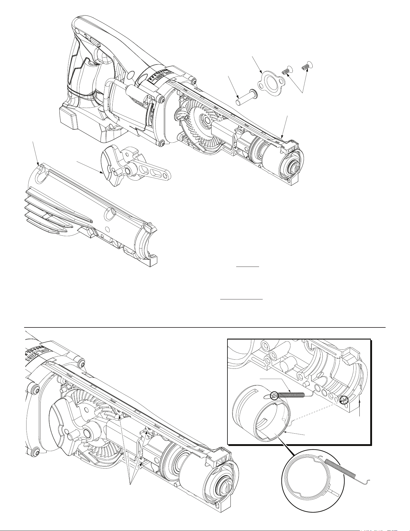
Orbit Slot
Screws (26)
Left Gearcase (71)
Barrel
Cam (9)
Extension
Spring (10)
As an aid to install Extension Spring (10), assemble gearcase
components as shown. Loosen but do not remove the four
orbit Slot Screws (26). This will allow for the front end
assembly, including the Barrel Cam (9) to pivot away
from the Left Gearcase (71). There should be enough
room to attach the Extension Spring to the top recess
area in the Barrel Cam and small hole in the bottom
front of the Left Gearcase. Spring should wrap
around the side of the Barrel Cam and
rest inside channel in the gearcase
half. Retighten the four Orbit
Slot Screws.
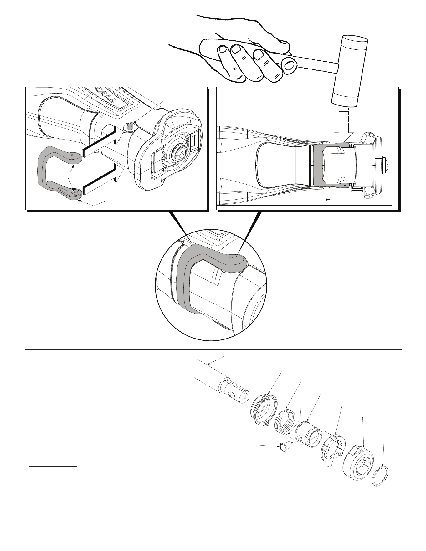
Shoe Pin
#23
Shoe Release Lever #22
Block
To properly install the Shoe Release Lever
#22 onto the Shoe Pin #23 do the following:
Insert the shoe pin through the hole in the
gearcase insulator. Center the shoe pin with
equal amounts of the pin protruding from each
side of the tool.
Rotate the shoe pin so the flats of the pin will
align with the flats in the shoe release lever
cavities.
The shoe release lever is stiff but flexible. Place
the shoe release lever over the gearcase
insulator. Lift one end of the shoe release lever
onto the shoe pin (with flats aligned) and press
into place.
Pull the other end of the shoe release lever over
the other side of the pin and press in place.
Flats
(both sides)
Place the tool on its side on a hard flat surface.
Place a small wood block approximately 1-1/8”
thick under the tool, between the hard surface
and the shoe release lever, directly beneath the
pin.
With a rubber mallet, strike the shoe release
lever several times to completely seat the lever
onto the pin and to asure that the pin is properly
centered within the gearcase.
REMOVING THE STEEL QUIK-LOK
®
BLADE CLAMP - VERSION 1
• Remove external retaining ring (7) and pull front cam (8) off.
• Pull lock pin (5) out and remove remainder of parts and discard.
REASSEMBLY OF THE STEEL QUIK-LOK
®
BLADE CLAMP
• Coat new lock pin with powdered graphite.
• Hold tool in a vertical position.
• Place spring cover onto spindle.
• Slide torsion spring (3) onto spindle with spring leg on hole side of spindle.
• Slide sleeve (6) onto spindle aligning hole on sleeve with hole in spindle.
• Slide rear cam over sleeve until it bottoms on sleeve shoulder, ensure spring leg inserts
into groove of cam.
• Rotate rear cam in the direction of the arrows located on spring cover until there is clearance for lock pin (5)
to be inserted into sleeve/spindle holes. Insert lock pin.
• Align front cam (8) inner ribs with rear cam outer slots and slide front cam onto sleeve until it bottoms.
Retaining ring groove should be completely visible.
• Attach retaining ring (7) by separating coils and inserting end of ring into groove, then wind remainder of ring into groove.
Ensure ring is seated in groove.
• Blade clamp should rotate freely. During normal usage, debris may not allow blade clamp to rotate freely. The use of spray lubricant can
help free blade clamp. In extreme conditions, follow these instructions to remove, clean and reassemble blade clamp.
Leg
Spindle (18)
Spring Cover (2)
Torsion Spring (3)
Sleeve (6)
Rear Cam (4)
Front Cam (8)
Retaining
Ring (7)
Lock Pin (5)
Hole/Groove
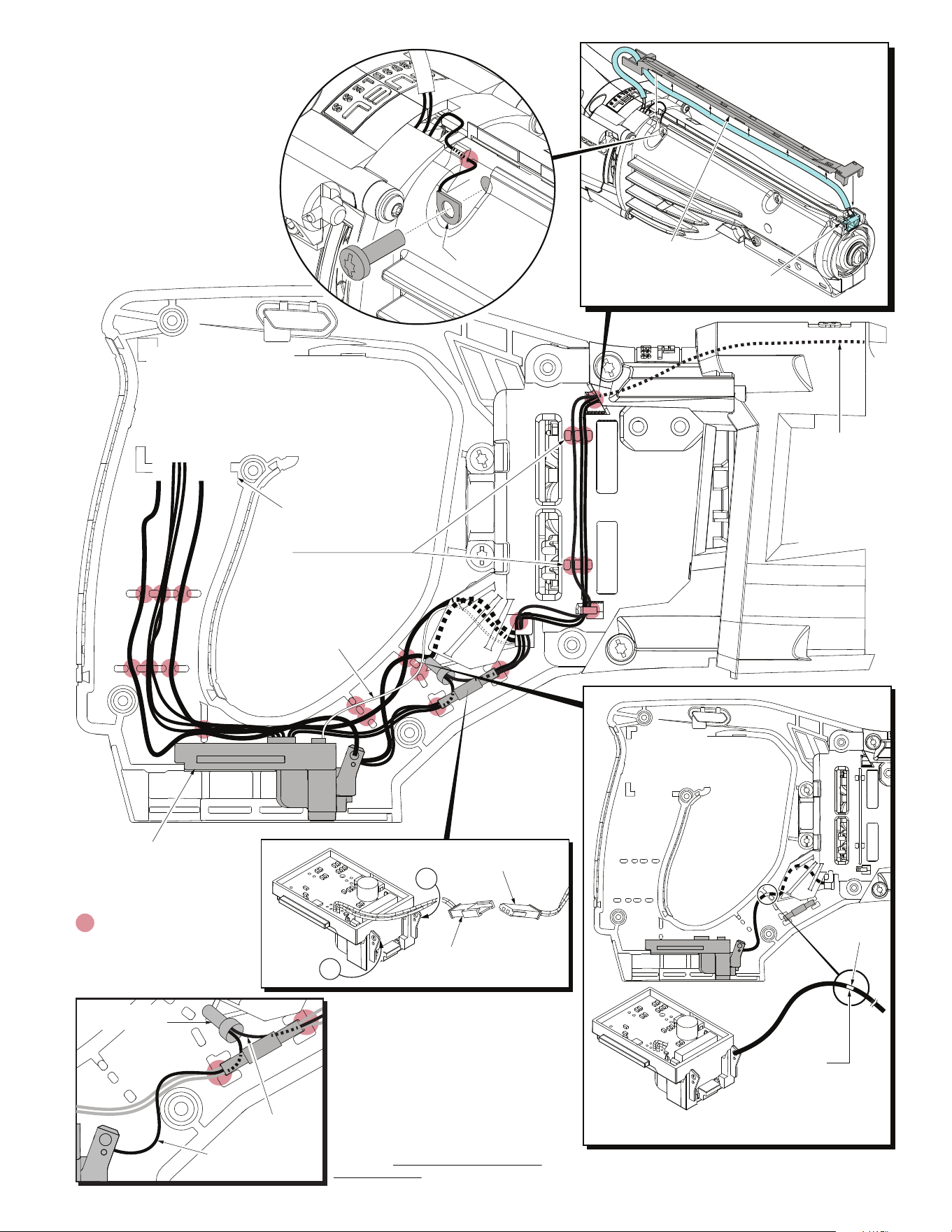
= WIRE TRAPS
or GUIDES
Wire Ribbon
LED Assembly #76
LED Tray #70
Route sleeved wires of the LED
Assembly #76 as shown, pressing/
trapping sleeve up into the LED
Tray #70. Place tray into the
top groove between
gearcase halves
and tighten
screws.
Connector from
LED Assembly #76
Connector from Control
Board/Terminal
Connector Block #51
+
+
Control Board/
Terminal Connector Block #51
On-Off
Switch #59
Mark
IMPORTANT:
For proper installation,
this black wire has a
mark on it that must be
placed in the wire trap
as shown.
High Voltage
Wire #92
Prior to installing the LED and Tray
Assembly #90, route High Voltage
Wire #92 around and through the
Motor Cage Assembly #89 as shown.
Secure to the Gearcase Halve #28
with Screw #29.
High Voltage
Wire #92
Closed End
Connector #93
NOTE:
Right Motor Cage #52 may not
have additional wire traps for
the High Voltage Wire. Use a
dab of RTV at these points
to hold wire in place.
High Voltage
Wire #92
Short black wire off
negative terminal
Closed End
Connector #93
Strip short black wire (from the negative
terminal of the Control Board/Terminal
Connector Block #51) to about 3/16”.
StripHigh Voltage Wire #92 to approxi-
mately 3/16”. Twist the metal strands of
both wires together. Twist a Closed End
Connector #93 over the wire strands.
Crimp the barrel of the connector to
secure the wires. Route the High Voltage
Wire as shown above starting with the HV
wire in the bottom of the LED/Terminal
connector cavity, under the joined
connectors.