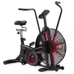
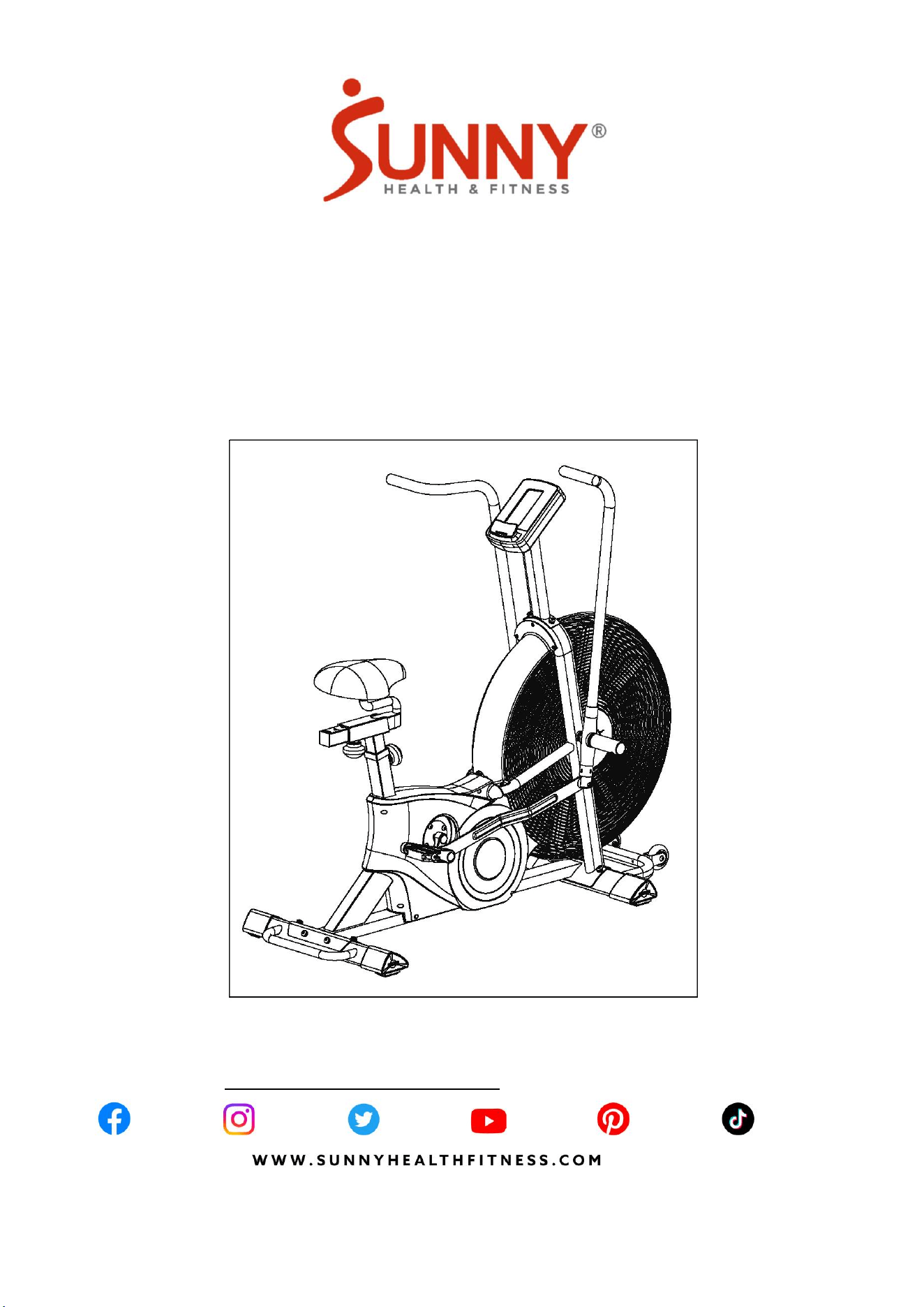
TORNADO SMART DUAL BELT
AIR-RESISTANCE BIKE
SF-B223018
USER MANUAL
IMPORTANT! Please retain owner’s manual for maintenance and adjustment instructions.
Your satisfaction is very important to us, PLEASE DO NOT RETURN UNTIL YOU HAVE
CONTACTED US: [email protected] or 1-877-90SUNNY (877-907-8669).

1
IMPORTANT SAFETY INFORMATION
We thank you for choosing our product. To ensure your safety and health, please use this
equipment correctly. It is important to read this entire manual before assembling and using the
equipment. Safe and effective use can only be achieved if the equipment is assembled,
maintained and used properly. It is your responsibility to ensure that all users of the equipment
are informed of all warnings and precautions.
1. Before starting any exercise program, you should consult your physician to determine if
you have any medical or physical conditions that could put your health and safety at risk,
or prevent you from using the equipment properly. Your physician’s advice is essential if
you are taking medication that affects your heart rate, blood pressure or cholesterol level.
2. Be aware of your body’s signals. Incorrect or excessive exercise can damage your health.
Stop exercising if you experience any of the following symptoms: pain, tightness in your
chest, irregular heartbeat, shortness of breath, lightheadedness, dizziness or feelings of
nausea. If you do experience any of these conditions, you should consult your physician
before continuing with your exercise program.
3. Keep children and pets away from the equipment. The equipment is designed for adult
use only.
4. Use the equipment on a solid, flat level surface with a protective cover for your floor or
carpet. To ensure safety, the equipment should have at least 2 feet (60 cm) of free space
all around it.
5. Ensure that all nuts and bolts are securely tightened before using the equipment. The
safety of the equipment can only be maintained if it is regularly examined for damage
and/or wear and tear.
6. Always use the equipment as indicated. If you find any defective components while
assembling or checking the equipment, or if you hear any unusual noises coming from the
equipment during exercise, discontinue use of the equipment immediately and do not use
until the problem has been rectified.
7. Wear suitable clothing while using the equipment. Avoid wearing loose clothing that may
become entangled in the equipment.
8. Do not place fingers or objects into the moving parts of the equipment.
9. The maximum weight capacity of this unit is 330 lbs (150 kgs).
10. The equipment is not suitable for therapeutic use.
11. To avoid bodily injury and/or damage to the product or property, proper lifting and moving
is required.
12. Your product is intended for use in cool, dry conditions. You should avoid storage in
extreme cold, hot or damp areas as this may lead to corrosion and other related problems.
13. This equipment is designed for indoor and home use only. It is not intended for
commercial use!
2
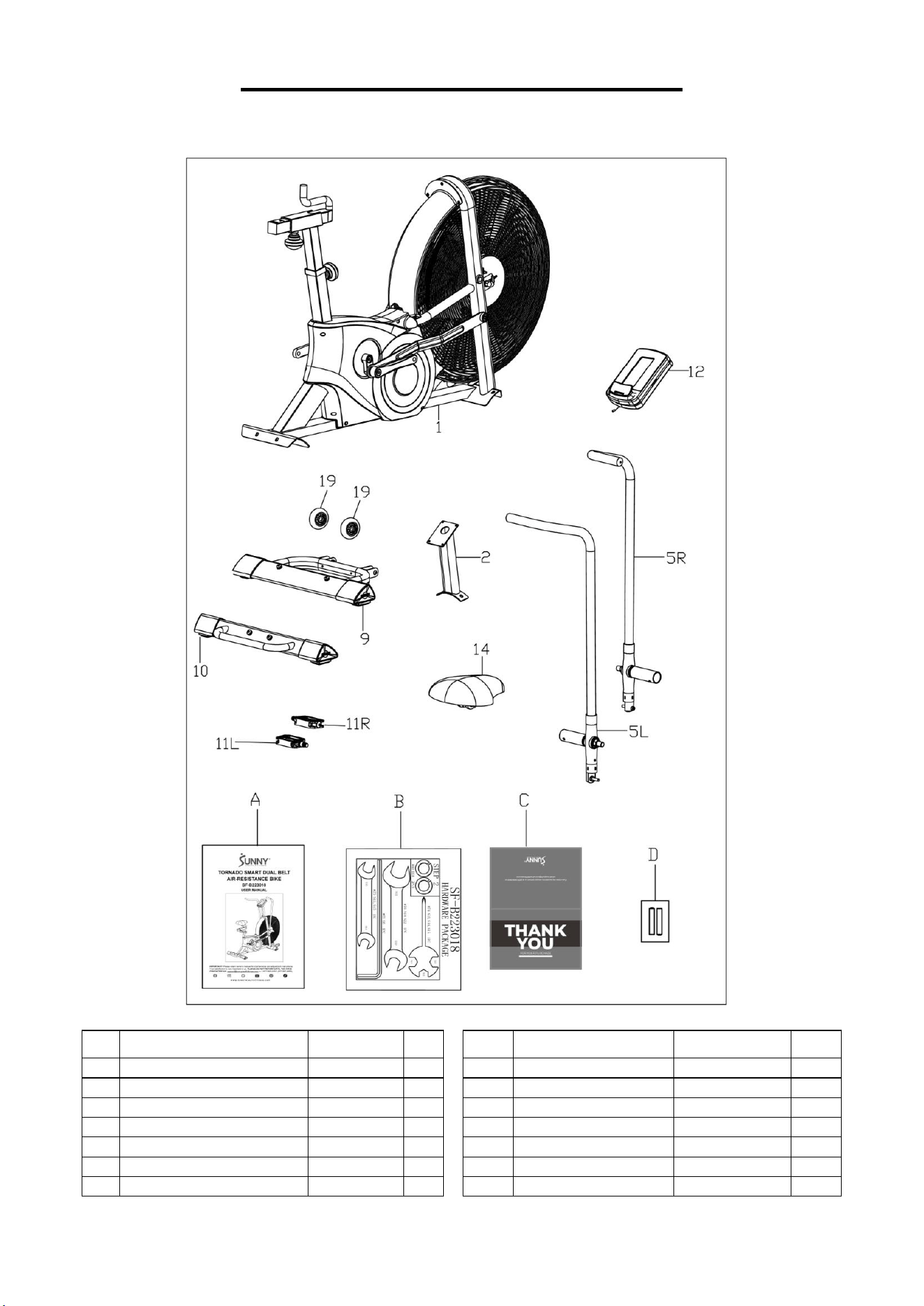
PRE-ASSEMBLY CHECK LIST
Before you start to assemble, please make sure all parts are included.
No.
Description
Spec.
Qty.
No.
Description
Spec.
Qty.
1
Main Frame
1
11R
Right Pedal
JD-303V
1
2
Handlebar Post
1
12
Meter
ST3921
1
5L
Left Swing Arm
1
19
Transportation Wheel
Φ72X24
2
5R
Right Swing Arm
1
A
Manual
1
9
Front Stabilizer
1
B
Hardware Package
1
10
Rear Stabilizer
1
C
Thank You Card
1
11L
Left Pedal
JD-303V
1
D
Battery
AA
2
3
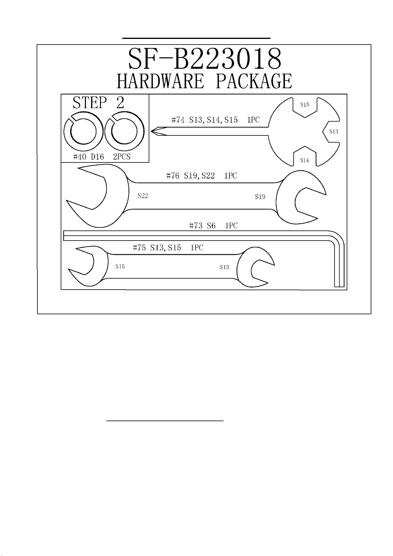
HARDWARE PACKAGE
Ordering Replacement Parts (U.S. and Canadian Customers only)
Please provide the following information in order for us to accurately identify the part(s)
needed:
✓ The model number (found on cover of manual)
✓ The product name (found on cover of manual)
✓ The part number found on the “EXPLODED DIAGRAM” (page 20) and “PARTS LIST”
(pages 19)
Please contact us at [email protected] or 1-877-90SUNNY (877-907-8669).
4
ASSEMBLY INSTRUCTIONS
We value your experience using Sunny Health and Fitness products. For assistance with parts or
troubleshooting, please contact us at suppo[email protected] or 1-877-90SUNNY
(877-907-8669).
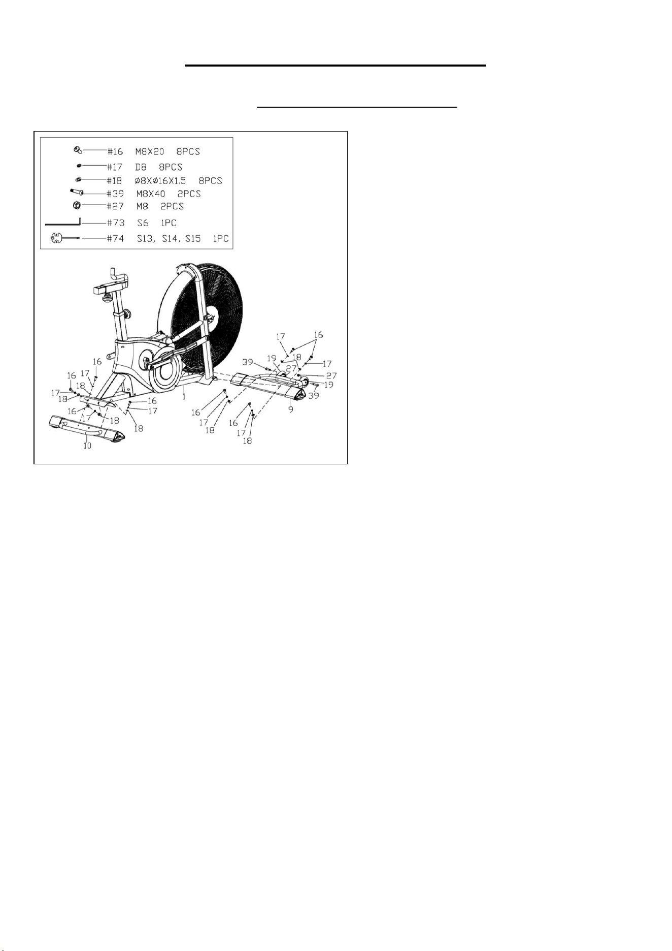
STEP 1:
Remove 8 Allen Screws (No. 16), 8 Spring
Washers (No. 17) and 8 Flat Washers (No.
18) from the Front Stabilizer (No. 9) and the
Rear Stabilizer (No. 10) using Allen
Wrench (No. 73).
Attach the Front Stabilizer (No. 9) and the
Rear Stabilizer (No. 10) to the Main Frame
(No. 1) with 8 Allen Screws (No. 16), 8
Spring Washers (No. 17) and 8 Flat
washers (No. 18) that were just removed.
Tighten and secure with Allen Wrench (No.
73).
Remove 2 Allen Screws (No. 39) and 2
Nylon Nuts (No. 27) from the Front
Stabilizer (No. 9) using Allen Wrench (No.
73) and Spanner (No. 74).
Attach the 2 Transportation Wheels (No.
19) to the Front Stabilizer (No. 9) with 2
Allen Screws (No. 39) and 2 Nylon Nuts
(No. 27) that were just removed. Tighten and
secure with Allen Wrench (No. 73) and
Spanner (No. 74).
5
We value your experience using Sunny Health and Fitness products. For assistance with parts or
troubleshooting, please contact us at suppo[email protected] or 1-877-90SUNNY
(877-907-8669).
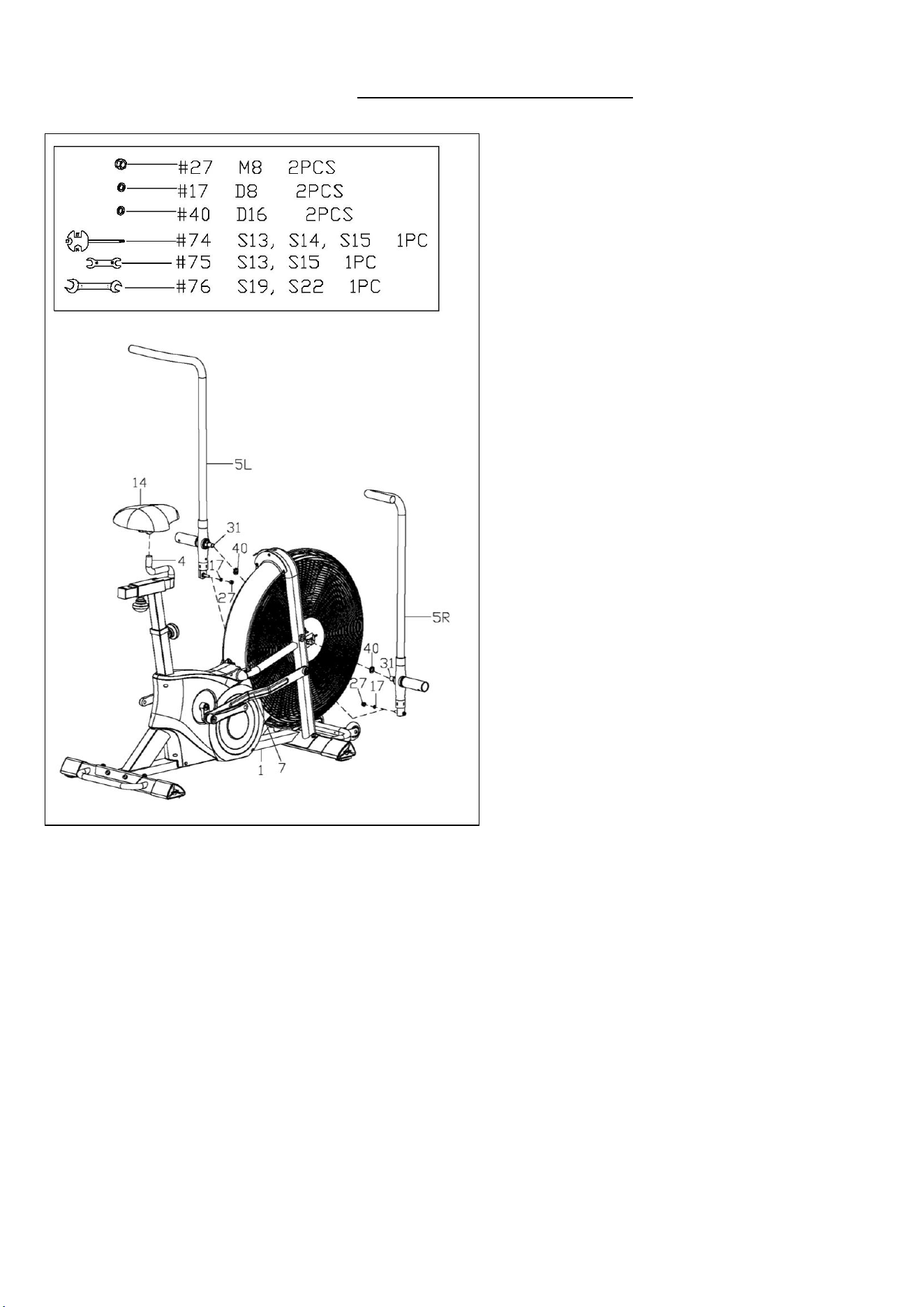
STEP 2:
Remove 2 Nylon Nuts (No. 27), 2 Spring
Washers (No. 17) from the Left & Right
Swing Arms (No. 5L & No. 5R) using
Spanner (No. 74).
Pre-attach the 2 Pedal Tube Axles (No. 31)
of the Left & Right Swing Arms (No. 5L &
No. 5R) and 2 Spring Washers (No. 40) to
the two sides of the Main Frame (No. 1)
using Open End Wrench (No. 76).
NOTE: Do not completely tighten the Pedal
Tube Axles (No. 31) yet.
Attach the Left & Right Swing Arms (No.
5L & No. 5R) to the 2 Connecting Arms
(No. 7) with 2 Nylon Nuts (No. 27) and 2
Spring Washers (No. 17) that were just
removed. Tighten and secure with Spanner
(No. 74).
Now, tighten the Pedal Tube Axles (No. 31)
using Open End Wrench (No. 76).
Attach the Seat (No. 14) onto the Seat
Slider (No. 4) and lock them tightly with
Open End Wrench (No. 75).
NOTE: Before exercise, please make sure
the Seat (No. 14) is tightened to the Seat
Slider (No. 4).
6
We value your experience using Sunny Health and Fitness products. For assistance with parts or
troubleshooting, please contact us at suppo[email protected] or 1-877-90SUNNY
(877-907-8669).
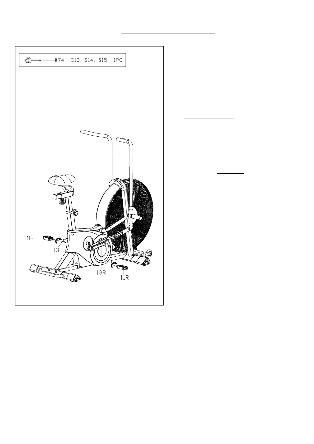
STEP 3:
IMPORTANT! Read instructions carefully,
failure to do so may cause permanent
damage to your bike.
Align the Left Pedal (No. 11L) with the Left
Crank (No. 13L) at a 90° angle and gently
insert the Left Pedal (No. 11L) into the Left
Crank (No. 13L). Screw the Left Pedal (No.
11L) counter-clockwise into the Left Crank
(No. 13L). Tighten and secure with Spanner
(No. 74).
Align the Right Pedal (No. 11R) with the
Right Crank (No. 13R) at a 90° angle and
gently insert the Right Pedal (No. 11R) into
the Right Crank (No 13R). Screw the Right
Pedal (No. 11R) clockwise into the Right
Crank (No. 13R). Tighten and secure with
Spanner (No. 74).
NOTE: Left Pedal (No. 11L) is marked with
“L” on the pedal, while Right Pedal (No.
11R) is marked with “R” on the pedal.
Attaching the Left & Right Pedals (No. 11L
& No. 11R) to the wrong Left & Right
Cranks (No. 13L & No. 13R) or turning them
with the wrong direction will damage the Left
& Right Cranks (No. 13L & No. 13R).
7
We value your experience using Sunny Health and Fitness products. For assistance with parts or
troubleshooting, please contact us at suppo[email protected] or 1-877-90SUNNY
(877-907-8669).
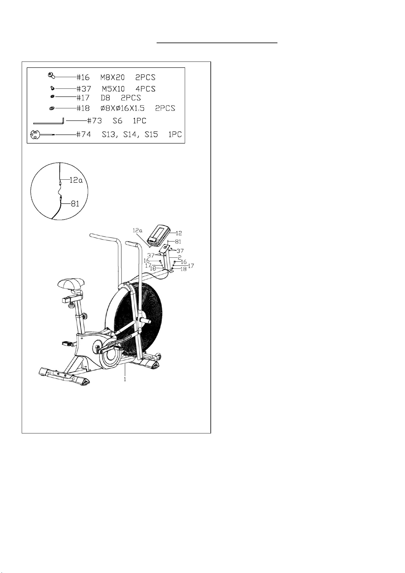
STEP 4:
Remove 2 Allen Screws (No. 16), 2 Spring
Washers (No. 17) and 2 Flat Washers (No.
18) from the Main Frame (No. 1) using Allen
Wrench (No. 73).
Thread the Sensor Wire (No. 81) through
the bottom of the Handlebar Post (No. 2)
and bring out from the top. Then attach the
Handlebar Post (No. 2) to the Main Frame
(No. 1) with 2 Allen Screws (No. 16), 2
Spring Washers (No. 17) and 2 Flat
Washers (No. 18) that were just removed.
Tighten and secure with Allen Wrench (No.
73).
Remove 4 Screws (No. 37) from the back of
the Meter (No. 12) using Spanner (No. 74).
Connect the Sensor Wire (No. 81) with the
Meter Wire (No. 12a), then attach the Meter
(No. 12) on the bracket of the Handlebar
Post (No. 2) with 4 Screws (No. 37) that
were just removed. Tighten and secure with
Spanner (No. 74).
THE ASSEMBLY IS COMPLETE!
8
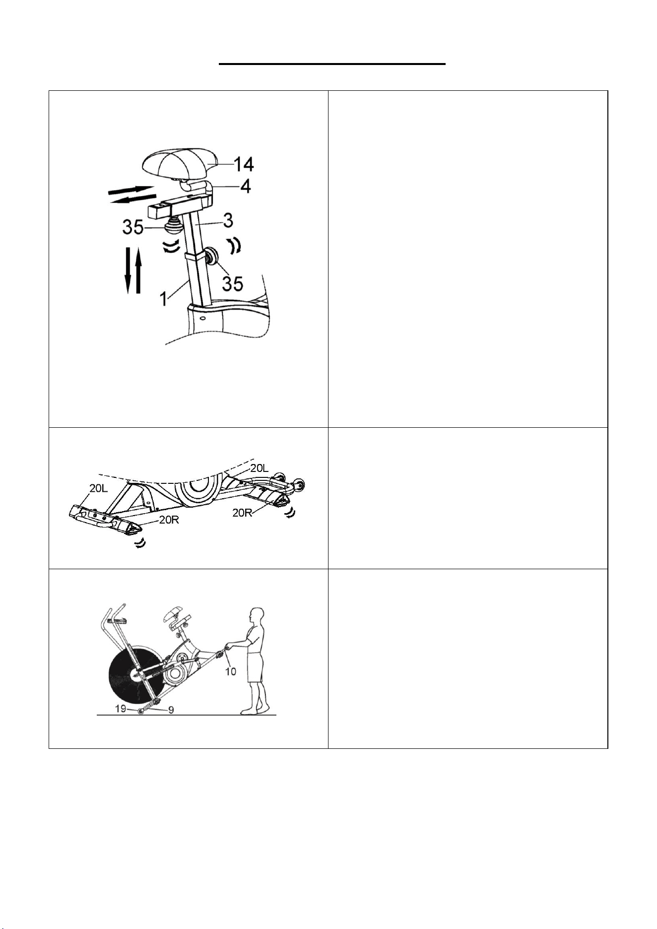
ADJUSTMENT GUIDE
ADJUSTING THE SEAT
The Seat (No. 14) of this bike is fully
adjustable as it moves Up, Down, Fore
(forward), Aft (backward).
To adjust the height of the Seat Tube (No. 3),
loosen and pull the Knob (No. 35) on the
Main Frame (No. 1) outward, then raise or
lower the Seat (No. 14) to the desired height.
Once adjusted, re-insert and tighten the
Knob (No. 35) to secure the Seat (No. 14) in
place.
To adjust the Seat (No. 14) back and forth,
loosen and pull the Knob (No. 35) on the
Seat Tube (No. 3) outward, then slide the
Seat Slider (No. 4) to the desired position.
Once adjusted, re-insert and tighten the
Knob (No. 35) to secure the Seat Slider (No.
4) in place.
ADJUSTING THE LEVEL
If at any point the bike feels uneven, you can
adjust the Left & Right Leveler Caps (No.
20L & No. 20R). If the bike is wobbly when
you use it, please consider adding an
exercise mat under it.
HOW TO MOVE THE BIKE
There are Transportation Wheels (No. 19)
located on the Front Stabilizer (No. 9). Hold
the handlebar on the Rear Stabilizer (No. 10)
and pull forward to lift the rear of the bike off
the floor. Now you can move the bike.
9
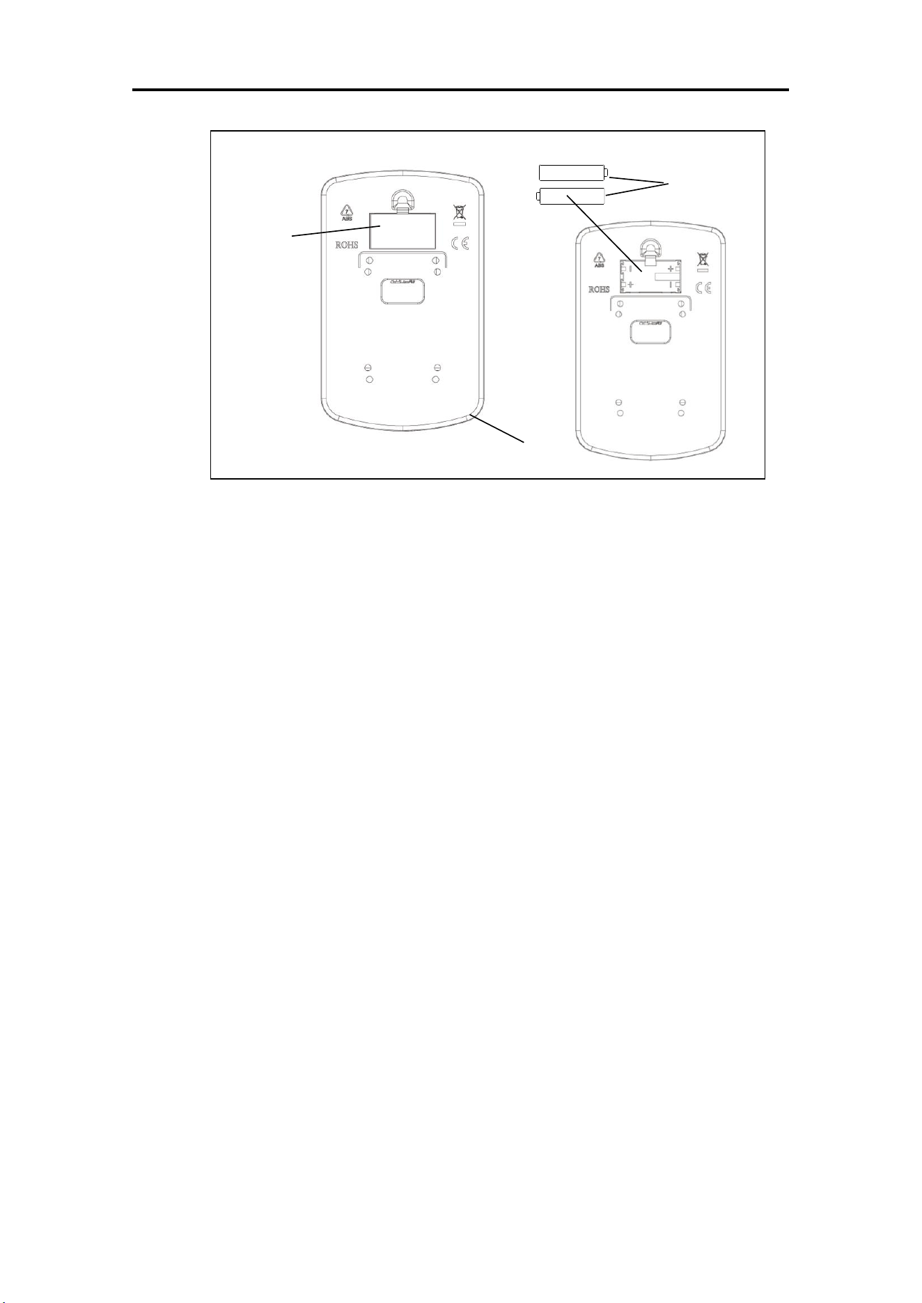
BATTERY INSTALLATION & REPLACEMENT
BATTERY INSTALLATION
1. Take out 2 AA batteries from meter box.
2. Press the buckle of battery cover on the Meter (No. 12), then remove battery cover.
3. Install 2 AA batteries into the battery case on the back of the Meter (No. 12). Pay attention
to the battery + and – poles before installing.
4. Press the buckle of battery cover, then put the battery cover back to the back of the Meter
(No. 12).
The installation is complete!
BATTERY REPLACEMENT
1. Press the buckle of battery cover on the back of the Meter (No. 12), then remove battery
cover.
2. Remove the 2 old AA batteries in the battery case and install 2 new AA batteries into the
battery case on the back of the Meter (No. 12). Pay attention to the battery + and – poles
before installing.
3. Press the buckle of battery cover, then put the battery cover back to the back of the Meter
(No. 12).
The replacement is complete!
BATTERY DISPOSAL
Dispose the batteries according to the laws and regulations of your local region. Some
batteries may be recycled. When disposing or recycling, do not mix battery types.
Battery
Battery
Cover
12
10
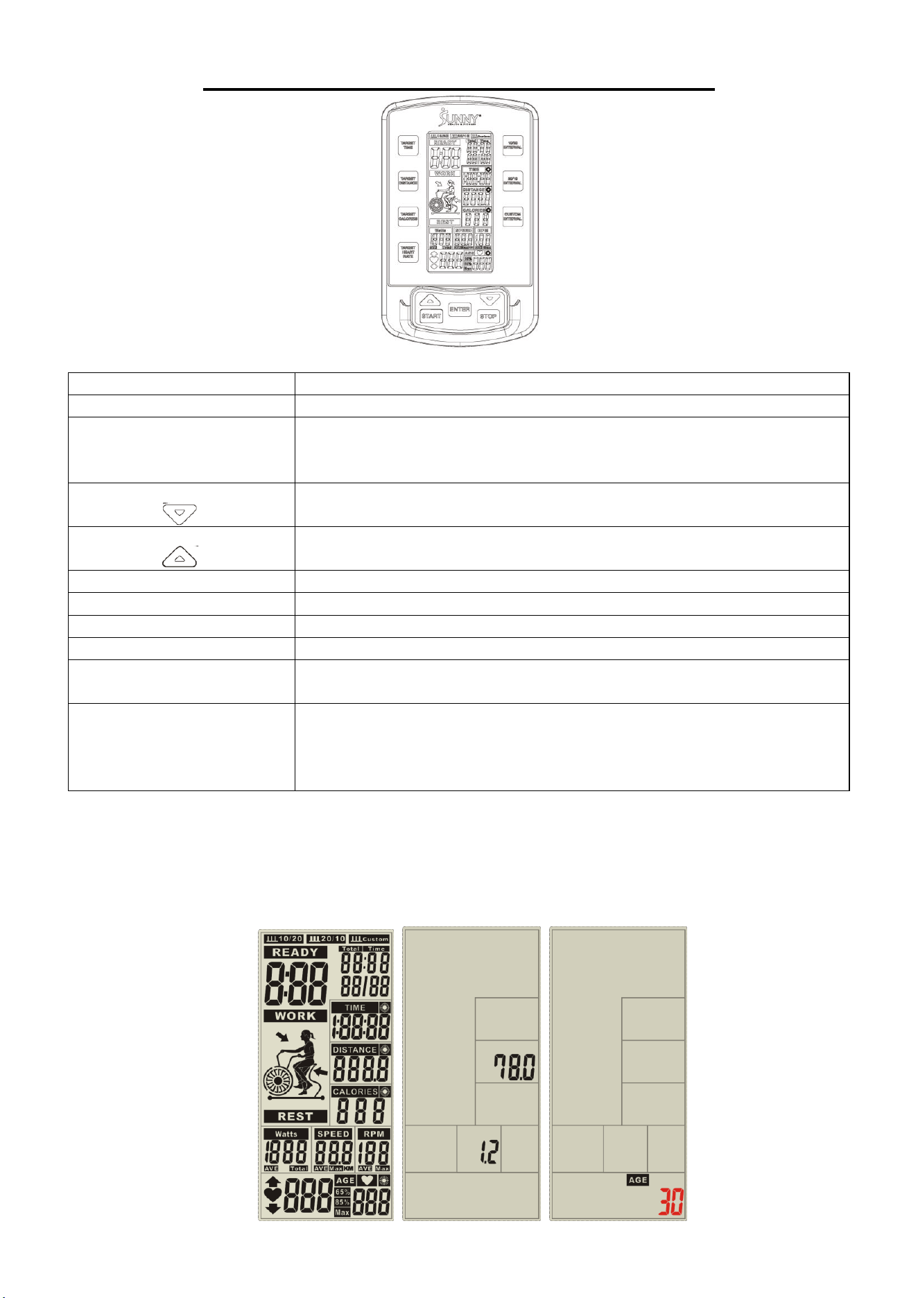
EXERCISE METER INSTRUCTIONS
BUTTON FUNCTIONS
FUNCTION
DESCRIPTION
START
To start workout quickly or resume workout in STOP mode.
STOP
To stop/pause workout.
To clear up all settings.
Hold on this key for 2 seconds to reboot the meter.
DOWN
To adjust DISTANCE, CALORIES, HEART RATE, TIME, AGE
value down.
UP
To adjust DISTANCE, CALORIES, HEART RATE, TIME, AGE
value up.
TARGET DISTANCE
Fast access to Target Distance training mode.
TARGET CALORIES
Fast access to Target Calories training mode.
TARGET HEART RATE
Fast access to Target Heart Rate training mode.
TARGET TIME
Fast access to Target Time training mode.
INTERVAL
There are 3 programs: 10/20 INTERVAL, 20/10 INTERVAL,
and CUSTOM INTERVAL.
ENTER
To confirm settings or enter program.
Press and hold the button for 6 seconds to disconnect from
both the SunnyFit APP and the heart rate monitor, the meter
will enter sleep mode.
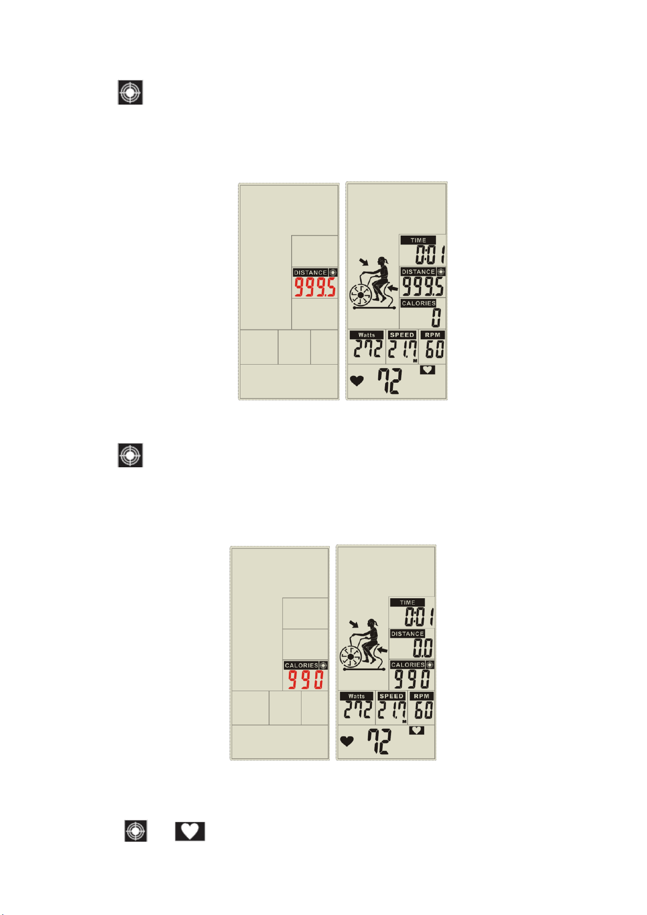
OPERATING INSTRUCTIONS
1. After the batteries are installed, the screen displays for 2 seconds (FIG. 1) and will beep at
the same time. Then the screen will display the wheel diameter for 1 second (FIG. 2) in the
DISTANCE window and enter the AGE setting. When entering the AGE, the age value will
flash (FIG. 3), press the UP/DOWN buttons to adjust the value, press the ENTER button to
confirm and enter standby mode.
FIG. 1
FIG. 2
FIG. 3
11
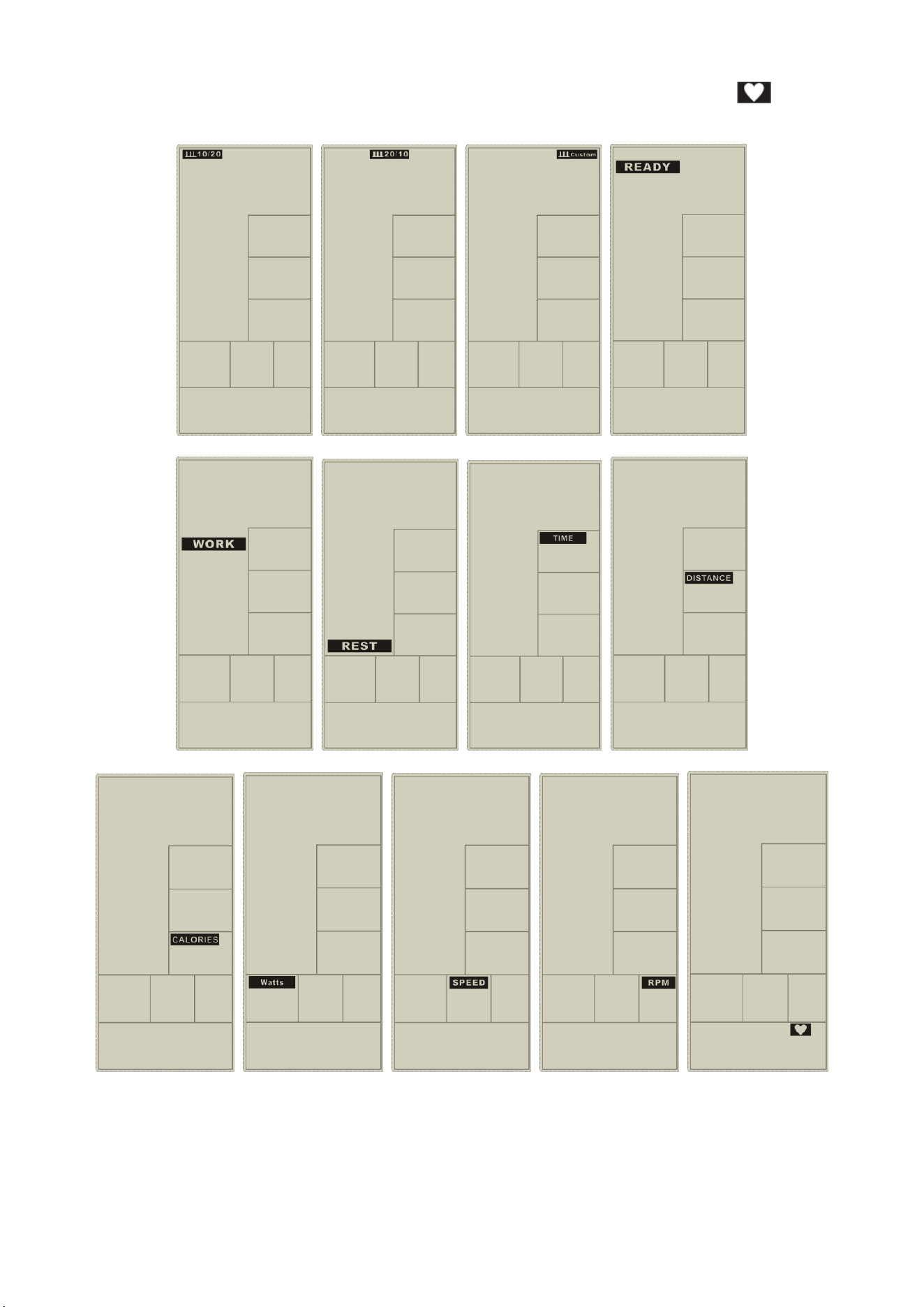
2. 10/20 INTERVAL, 20/10 INTERVAL, CUSTOM INTERVAL, READY, WORK, REST, TIME,
DISTANCE, CALORIES, WATTS, SPEED, RPM, and HEART RATE symbol will
cycle though in SCAN mode (FIG. 4 to FIG. 16).
3. If there is no button input and no RPM signal input for 60 seconds, the meter will enter
sleep mode.
4. Manual Program:
1) In standby mode, if there is RPM signal input, the meter will start immediately and beep
at the same time.
2) TOTAL TIME, TIME, DISTANCE, CALORIES, WATTS, SPEED and RPM will start
FIG. 4
FIG. 5
FIG. 6
FIG. 7
FIG. 8
FIG. 9
FIG. 10
FIG. 11
FIG. 12
FIG. 13
FIG. 14
FIG. 15
FIG. 16

12
counting according to the calculation value (FIG. 17).
3) When there is heart rate input, the heart rate symbol will light up, and the
symbol will blink and display the current heart rate value (FIG. 18); "P" will blink
continuously if there is no heart rate input (FIG. 17).
4) After 30 seconds without any signal input, the meter will beep and enter standby mode.
5. 10/20 INTERVAL:
1) Press 10/20 INTERVAL button to enter 10/20 INTERVAL mode. The 10/20 symbol will
light up on the top left corner of the screen and the meter will beep at the same time.
2) CYCLE TIME starts in 3 seconds, the meter will beep and READY will flash once per
second, and the count will display 00/08 (FIG. 19).
3) The CYCLE TIME will start to count down from 10 seconds and WORK will flash once
every second. The TIME window will count down from 3:40. TOTAL TIME, DISTANCE,
CALORIES, WATTS, SPEED and RPM will start counting according to the calculation
value. The count shows 01/08 (FIG. 20).
4) The CYCLE TIME will start to count down from 20 seconds and REST will flash once
every second. The meter will beep synchronously (FIG. 21). READY will flash
synchronously at the last 3 seconds (FIG. 22).
5) Repeat STEP 3 and STEP 4 for each cycle. Each cycle count adds 1, until 08/08
WORK movement is displayed, then enter the end screen.
6) Under the execution of the WORK movement, after 30 seconds without any signal input,
the meter will beep and enter standby mode.
6. 20/10 INTERVAL:
1) Press 20/10 INTERVAL button to enter 20/10 INTERVAL mode. The 20/10 symbol will
light up on the top center of the screen, and the meter will beep at the same time.
FIG. 19
FIG. 20
FIG. 21
FIG. 22
FIG. 17
FIG. 18

13
2) CYCLE TIME starts in 3 seconds, the meter will beep and READY will flash once per
second, and the count will display 00/08 (FIG. 23).
3) The CYCLE TIME will start to count down from 20 seconds and WORK will flash once
every second. The TIME window will count down from 3:50. TOTAL TIME, DISTANCE,
CALORIES, WATTS, SPEED and RPM will start counting according to the calculation
value. The count shows 01/08 (FIG. 24).
4) The CYCLE TIME will start to count down from 10 seconds and REST will flash once
every second. The meter will beep synchronously (FIG. 25). READY will flash
synchronously at the last 3 seconds (FIG. 26).
5) Repeat STEP 3 and STEP 4 for each cycle. Each cycle count adds 1, until the 08/08
WORK movement is displayed, then enter the end screen.
6) Under the execution of the WORK movement, after 30 seconds without any signal input,
the meter will beep and enter standby mode.
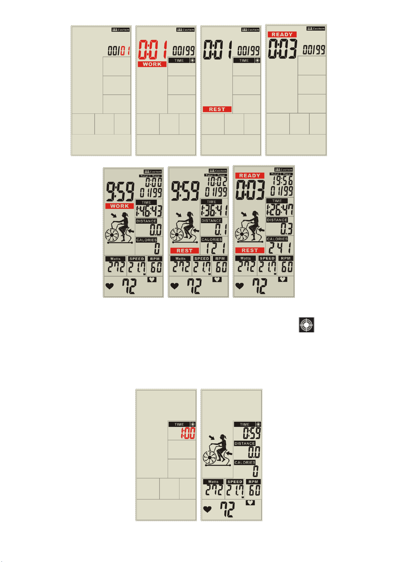
7. CUSTOM INTERVAL:
1) Press the CUSTOM INTERVAL button to enter CUSTOM INTERVAL mode. The
CUSTOM symbol will light up on the top right corner of the screen, 00/XX will flash and
the meter will beep at the same time. Press UP or DOWN button to set 00/XX. The
setting range is 1~99. Range will cycle through after 99 and restart from 1. Press the
ENTER button to confirm after the meter will beep and enter the next option setting
(FIG. 27).
2) TIME will light up, WORK and 0:01 will flash, press UP or DOWN button to set the
working time. The setting range is 0:01~9:59. It will cycle through after 9:59 and restart
from 0:01. Press the ENTER button to confirm after the meter will beep and enter the
next option setting (FIG. 28).
3) TIME will light up, REST and 0:01 will flash, press UP or DOWN button to set the
resting time. The setting range is 0:01~9:59. It will cycle through after 9:59 and restart
from 0:01. Press the ENTER button to confirm after the meter will beep and CUSTOM
will continue to light up (FIG. 29).
4) CYCLE TIME starts in 3 seconds, the meter will beep and READY will flash once per
second and the count will display 00/XX (FIG. 30)
5) The CYCLE TIME starts to count down from the setting time and WORK will flash once
every second. TOTAL TIME, DISTANCE, CALORIES, WATTS, SPEED and RPM will
start counting according to the calculation value. The count shows 01/XX (FIG. 31).
6) The CYCLE TIME will start to count down from the setting time and REST will flash
once every second. The meter will beep synchronously (FIG. 32). READY will flash
synchronously at the last 3 seconds (FIG. 33).
7) Repeat STEP 5 and STEP 6 for each cycle. Each cycle count adds 1, until all the
setting WORK movement are finished, then enter the end screen.
8) Under the execution of the WORK movement, after 30 seconds without any signal input,
the meter will beep and enter standby mode.
FIG. 23
FIG. 24
FIG. 25
FIG. 26
14
8. TARGET TIME:
1) Press the TARGET TIME button to enter TARGET TIME mode. The icon and
TIME will light up and the meter will beep at the same time.
2) The TIME value will flash, press UP or DOWN button to set the TIME (FIG. 34). Press
the ENTER button to confirm.
3) A countdown will start, then DISTANCE, CALORIES, WATTS, SPEED and RPM will
start counting according to the calculation value (FIG. 35).
4) After 30 seconds without any signal input, the meter will beep and enter standby mode.
FIG. 27
FIG. 28
FIG. 29
FIG. 30
FIG. 31
FIG. 32
FIG. 33
FIG. 34
FIG. 35
15
9. TARGET DISTANCE
1) Press the TARGET DISTANCE button to enter TARGET DISTANCE mode.
The icon and DISTANCE will light up and the meter will beep at the same time.
2) The DISTANCE value will flash, press UP or DOWN button to set the DISTANCE (FIG.
36). Press the ENTER button to confirm.
3) A countdown will start, then TIME, CALORIES, WATTS, SPEED and RPM will start
counting according to the calculation value (FIG. 37).
4) After 30 seconds without any signal input, the meter will beep and enter standby mode.
10. TARGET CALORIES:
1) Press the TARGET CALORIES button to enter TARGET CALORIES mode.
The icon and CALORIES will light up and the meter will beep at the same time.
2) The CALORIES value will flash, press UP or DOWN button to set the CALORIES (FIG.
38). Press the ENTER button to confirm.
3) A countdown will start, then TIME, DISTANCE, WATTS, SPEED and RPM will start
counting according to the calculation value (FIG. 39).
4) After 30 seconds without any signal input, the meter will beep and enter standby mode.
11. TARGET HEART RATE:
1) Press the TARGET HEART RATE button to enter TARGET HEART RATE mode.
The and icons will light up and the meter will beep the same time.
NOTE: the mode is only available when connected to the SunnyFit Heart Rate
Monitor HR200. The heart rate monitor is not included.
FIG. 36
FIG. 37
FIG. 38
FIG. 39
16
2) The AGE value will flash, press UP or DOWN button to set the age (FIG. 40). Press
the ENTER button to confirm.
3) Once started, MAX symbol will remain lit up and display the heart rate value of 65%
and 85%. TIME, DISTANCE, CALORIES, WATTS, SPEED and RPM will start
counting according to the calculation value (FIG. 41).
4) When the heart rate drops 65%, and the 65% value will flash, the meter will beep
every 10 seconds until the heart rate reaches above 65% (FIG. 42).
5) When the heart rate exceeds 85%, and the 85% value will flash, the meter will
beep every 10 seconds until the heart rate reaches below 85% (FIG. 43).
6) When the heart rate is in the range of 65%~85%, the heart rate symbol will flash, and
MAX/65%/85% will not be displayed, indicating that it is in the range of 65%~85%
(FIG. 44).
7) After 30 seconds without any signal input, the meter will beep and enter standby
mode.
SPECIAL FUNCTION DESCRIPTION
1. Setting pattern
1) In standby mode, long press the START and ENTER buttons for 2 seconds, after
entering the meter will beep, DISTANCE will light up, M (FIG. 45) and KM (FIG. 46)
blink once per second.
2) Press UP or DOWN button to switch between imperial and metric system. Press the
ENTER button to confirm. After the meter will beep and enter standby mode.
3) If there is no input for 30 second, the meter will enter standby mode.
FIG. 40
FIG. 41
FIG. 42
FIG. 43
FIG. 44
FIG. 45
FIG. 46
17
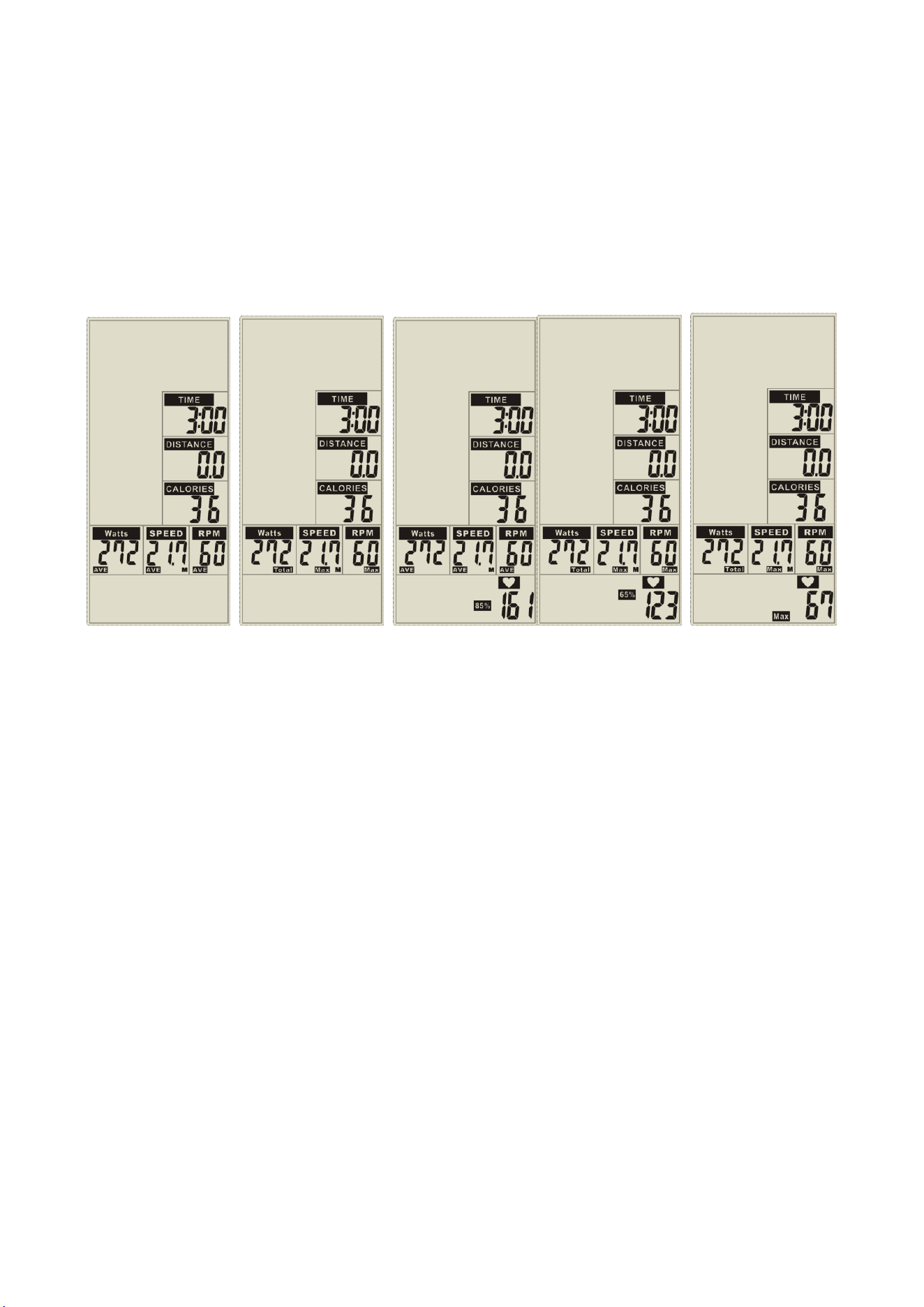
2. Press the START button once to enter pause mode. The meter will beep every 30
seconds. When in pause mode, all displays will remain on the screen for 3 seconds and
then blink on the 4th second. After 5 minutes in pause mode, the meter will beep and
enter standby mode, press START button to continue.
3. Press the STOP button and the meter will beep, TIME window displays the time elapsed
for the current exercise, DISTANCE window displays the current distance, and
CALORIES window displays current heat consumption for 30 seconds. WATT, SPEED,
and RPM windows display average and maximum values every 5 seconds.
4. In STOP mode, when there is heart rate input, heart rate values of 85%, 65% and the
maximum heart rate value are displayed every 5 seconds (FIG. 49- FIG. 51). If there is no
heart rate input, nothing will be displayed (FIG. 47- FIG. 48).
5. Reset mode:
1) Press the STOP button for 2 seconds in any case to TOTAL RESET.
2) The screen will blink once every 2 seconds, and the meter will beep for 2 seconds.
3) Return to standby mode, all settings will be reset and return to default presets.
WIRELESS HEART RATE:
1. The meter will turn on Bluetooth scan for wireless heart rate connection when the meter is
on or wakes from sleep mode. If no heart rate monitor is connected within 1 minute, press
the ENTER button to start the Bluetooth scan again.
2. If no heart rate monitor is connected, the meter will start the Bluetooth scan for wireless
heart rate connection for 1 minute when starting exercise.
3. After exercise resumes, if no heart rate monitor is connected, the meter will start the
Bluetooth scan for wireless heart rate connection for 1 minute.
FIG. 47
FIG. 50
FIG. 48
FIG. 49
FIG. 51

18
APP CONNECTION:
Connect Smart Equipment to SunnyFit App:
1. Scan to download SunnyFit from the app store:
2. Ensure that the Bluetooth function is turned on from your mobile device.
3. If this is your first time using the SunnyFit app, follow the in-app instructions to register
for your free SunnyFit account and log in.
4. Begin any workout activity that matches your smart equipment, then follow the onscreen
prompts to search for and connect to your smart equipment.
5. When connected, your stats and records will be displayed at the end of your
course/session and recorded in your account profile!
Troubleshooting:
•
If you are having trouble connecting your smart equipment, visit
www.sunnyfit.com/guide or scan the QR code below:
•
If you require additional support, please contact [email protected].
TECHNICAL DATA
Connectivity: Bluetooth LE
Frequency Range: 2400~2483.5 Mhz
Transmitting Power: 0 dBm

19
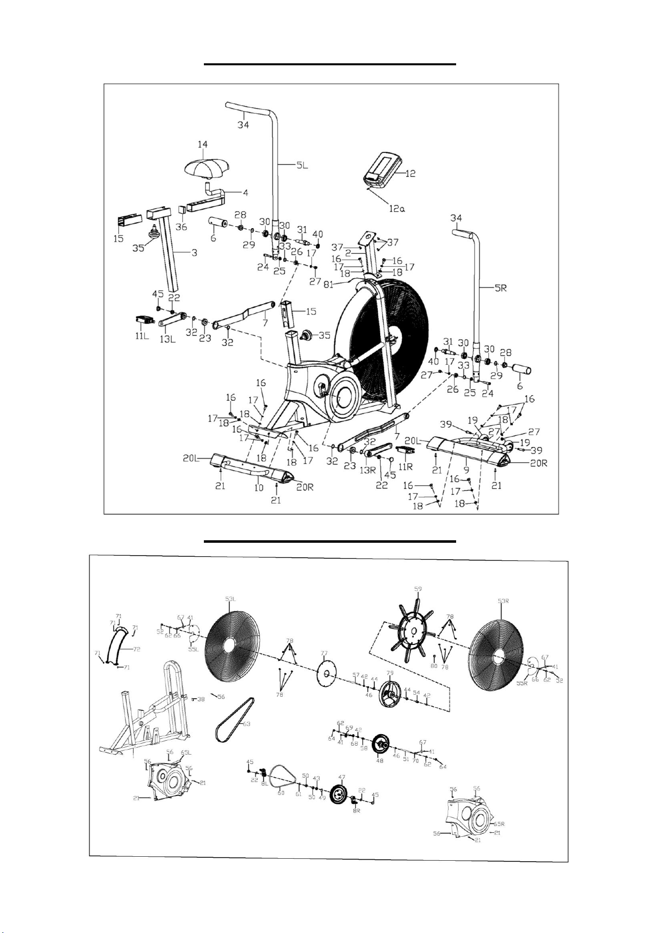
PARTS LIST
No.
Description
Spec.
Qty.
No.
Description
Spec.
Qty.
1
Main Frame
1
40
Spring Washer
D16
2
2
Handlebar Post
1
41
Hex Nut
M6
4
3
Seat Tube
1
42
Hex Thin Nut
M10X1.0
3
4
Seat Slider
1
43
Spacer
Φ17.2XΦ21X5
1
5L
Left Swing Arm
1
44
Bearing
6000Z
2
5R
Right Swing Arm
1
45
Crank Cover
4
6
Foot Tube
2
46
Thin Cone Nut
M10X1.0
2
7
Connecting Arm
2
47
Centre Axle Set
1
8L
Left Small Crank
70X27X25
1
48
Wheel Hub Set
1
8R
Right Small Crank
70X27X25
1
49
Wave Washer
Φ17XΦ25X0.3
1
9
Front Stabilizer
1
50
Bearing
6203Z
2
10
Rear Stabilizer
1
51
Crank Axle
Φ10X150
1
11L
Left Pedal
JD-303V
1
52
Cap Nut
M10X1.0
2
11R
Right Pedal
JD-303V
1
53L
Left Protective Cage
1
12
Meter
ST3921
1
53R
Right Protective Cage
1
12a
Meter Wire
150mm
1
54
Spacer
Φ10.2XΦ15X19
1
13L
Left Crank
L170,9/16"X20
1
55L
Left Cage Cover
1
13R
Right Crank
L170,9/16"X20
1
55R
Right Cage Cover
1
14
Seat
KX98-7
1
56
Self-drilling Screw
ST4.2X18
7
15
Bushing
45X45X1.5
2
57
Fan Wheel Axle
Φ10X150
1
16
Allen Screw
M8X20
10
58
Spacer
Φ10XΦ15X6
1
17
Spring Washer
D8
12
59
Fan Wheel
Φ620X49
1
18
Flat Washer
Φ8XΦ16X1.5
10
60
Belt
305
1
19
Transportation Wheel
Φ72X24
2
61
Axle Stop Ring
Φ17
1
20L
Left Leveler Cap
2
62
Flat Washer
D10XΦ20X2
4
20R
Right Leveler Cap
2
63
Belt
500
1
21
Screw
ST4.2X18
8
64
Flange Nut
M10X1.0
2
22
Flange Nut
M10X1.25
4
65L
Left Belt Cover
1
23
Bearing
99502Z
2
65R
Right Belt Cover
1
24
Shoulder
Φ10X44.5
2
66
Adjusting Bolt
M6X50
2
25
Hex Thin Nut
M8XH5
2
67
Adjusting U Washer
3X30X20
3
26
Bearing
Φ22XΦ8XH9
2
68
Adjusting Bolt
M6X48
1
27
Nylon Nut
M8
4
69
Adjusting U Washer
2X34.6X31
1
28
Flange Nut
M14X1.5
2
70
Adjusting Bolt
M6X36
1
29
Flat Washer
Φ17XΦ22X1
2
71
Screw
ST4.8X16
5
30
Bearing
6003Z
4
72
Fan Wheel Cover
1
31
Pedal Tube Axle
Φ22X94
2
73
Allen Wrench
S6
1
32
Wave Washer
Φ16XΦ22X0.3
4
74
Spanner
S13, S14, S15
1
33
Stop Ring
Φ22
2
75
Open End Wrench
S13, S15
1
34
Foam Grip
Φ28XΦ34X265
2
76
Open End Wrench
S19, S22
1
35
Knob
M16X1.5XL20
2
77
Seal Cover
Φ250X4
1
36
Square Cap
38X38X1.5
1
78
Screw
M6X12
16
37
Screw
M5X10
4
79
Flywheel
Φ246X36
1
38
Sensor Seat
1
80
Round Magnet
Φ15X6
1
39
Allen Screw
M8X40
2
81
Sensor Wire
700mm
1
20
EXPLODED DIAGRAM 1
EXPLODED DIAGRAM 2
Version: 1.1