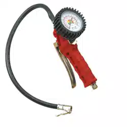

RECHARGEABLE/12V TYRE INFLATOR &
HIGH VOLUME PUMP, AIR COMPRESSOR, LED
WORKLIGHT, PSI, KPA AND BAR
MODEL NO’S: MAC13DR
Thank you for purchasing a Sealey product. Manufactured to a high standard, this product will, if used according to these instructions,
and properly maintained, give you years of trouble free performance.
IMPORTANT: PLEASE READ THESE INSTRUCTIONS CAREFULLY. NOTE THE SAFE OPERATIONAL REQUIREMENTS, WARNINGS & CAUTIONS. USE
THE PRODUCT CORRECTLY AND WITH CARE FOR THE PURPOSE FOR WHICH IT IS INTENDED. FAILURE TO DO SO MAY CAUSE DAMAGE AND/OR
PERSONAL INJURY AND WILL INVALIDATE THE WARRANTY. KEEP THESE INSTRUCTIONS SAFE FOR FUTURE USE.
1. SAFETY
WARNING! Read instructions before use. Suitable for 12V operation only.
WARNING! This compressor is capable of producing a high pressure. DO NOT inate any item beyond its maximum capacity.
WARNING! This device may be used by children aged 8 years and older, and by persons with reduced physical, sensory or mental
capacities, or a lack of experience and knowledge, if they are supervised or have been instructed in how to use the device safely and
understand the dangers that may arise when using it.
WARNING! The user is responsible for any damage or injury to third parties that was caused by the use of the device.
WARNING! During operation, never point the device at yourself or other individuals, and keep the device well way from your ears and
eyes.
9 There is a risk of injury!
8 DO NOT leave the unit unattended while in operation.
9 Check capacity and maximum pressure of inatable before commencing ination.
9 Monitor the pressure gauge while in operation.
9 The gauge should be used as an indication of pressure only. We recommend the use of a dial pressure gauge for denitive reading.
9 Locate compressor on an appropriate surface for use.
9 The 12V auxiliary plug must not be substituted with any other type of plug or electrical supply.
8 DO NOT direct ination hose connector head at yourself, others or animals.
8 DO NOT allow children to play with the device.
9 Keep children and non essential persons away from the ination area.
8 DO NOT carry by the hose, or pull the hose sharply from a valve.
8 DO NOT pull the power cable from the vehicle accessory socket or battery terminal by the power lead.
8 DO NOT get the compressor wet or use in the rain.
8 DO NOT use the compressor for a task it was not designed to perform.
8 DO NOT operate the compressor when you are tired, under the inuence of alcohol, drugs or intoxicating medication.
8 DO NOT operate the compressor if any parts are missing as this may cause failure or possible personal injury.
8 DO NOT open the unit.
8 DO NOT leave the device unsupervised while running. Comply with the lling instructions for the inatable item. The inatable item
could burst and cause serious injuries.
WARNING! When inating tyres which are completely at or articles with high volume low pressure, monitor temperature, as it can
overheat rapidly in the absence of back pressure. A 10 minute rest period should be observed after 15 minutes of continuous run time
to extend compressor service life.
9 Keep the compressor clean and in good condition.
9 Replace or repair damaged parts. Use recommended parts only. Non authorised parts may be dangerous and will invalidate the
warranty.
9 The integrated compressor unit is designed to adjust the pressure in tyres (e.g. car, motorbike and bicycle tyres), and for the generation
of pressure for balls and other low-pressure inatable items.
2. INTRODUCTION
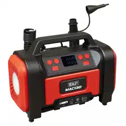
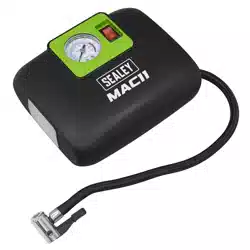
Suitable for inflating tyres on cars, vans, 4x4s, motorcycles and bicycles. High volume air pump with inflate/deflate function suitable for air
mattresses and inflatables. Rechargeable unit, supplied with 12V plug for alternative power option when battery has run flat. Maximum
pressure 120psi. Air flow rate 350L/min with an inflation time of 240 seconds (0-30psi). Pressure units in psi, kPa and bar. Auto-shut-
off safety feature when pre-set pressure is reached. Power bank with USB output 5V 2A ideal for charging mobile phones and portable
devices. Integrated SMD LED worklight with red SOS and flashing light function. Easy-to-read backlit LCD digital display screen. Compact
and lightweight unit with accessories fixed to the housing. Anti-vibration feet. Accessory kit includes Schrader connection, Presta type
adaptor, ball spike, inflatables adaptor and USB-C charging cable.
MAC13DR Issue:2 20/03/25
Original Language Version
© Jack Sealey Limited
Refer to
instruction
manual
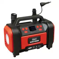
6. SPECIFICATIONe
MAC13DR Issue:2 20/03/25
Original Language Version
© Jack Sealey Limited
Model No: MAC13DR
Airow: 350L/min/18.45cfm
Battery: 2000mAh (x3)/ 11.1V 2Ah 22.2Wh Li-ion
High Volume Hose Length: 450mm
Hose Length: 550mm
Nett Weight: 1.4kg
Pressure Units: KPa, bar, psi, kg/cm²
Range: 0-120psi(0-8bar)
Working Voltage: 12V
Continuous Working Time: 30mins
Max Current: 10A
USB Output/Input: 5V/2A
Supply: 11.1V 2Ah 22.2Wh Li-ion Battery or
12V-10A
Ination Time (175/70/R13): 0-30psi in 241sec (Internal Battery)/
0-30psi in 254sec (12V Supply)
Max. Air Output: 120psi (8.3bar)
Charging Time: 3-5hr
LED Light: 3 Modes
Accessories: Schader Connection, Presta Valve
Adaptor, Ball needle, Inatables
Adaptor, USB-C Charging Cable
Power: 120W
Cable length: 3m
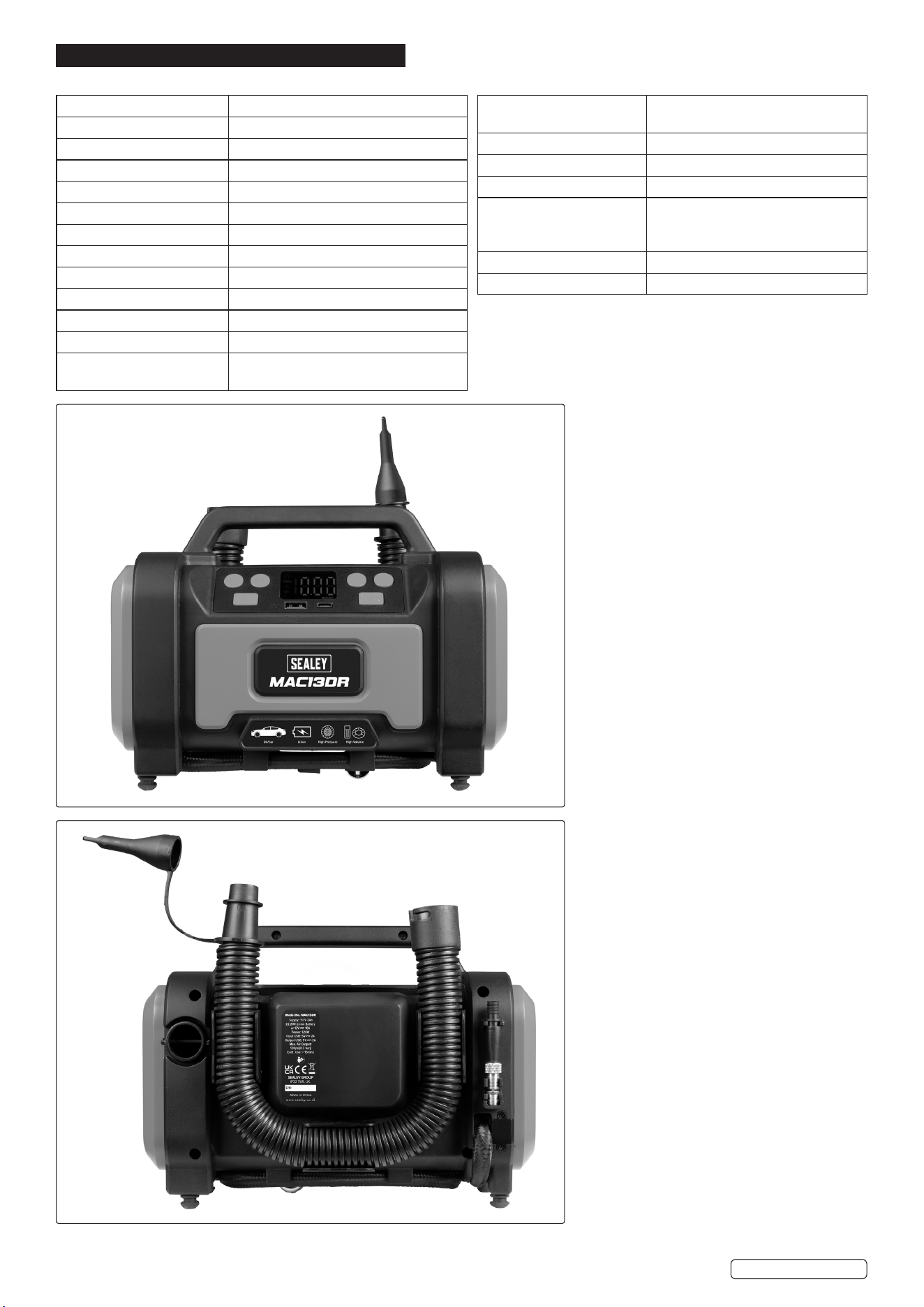
3. FEATURES
4. SPARES
Original Language Version
© Jack Sealey Limited
MAC13DR Issue:2 20/03/25
Part Description
1 LED Button
2 Mode selection
3 Digital Display
4 “+” Button
5 “-” Button
6 High-volume Tapered Nozzle
7 Ination Mode Switch (R:High-pressure Mode,
L:High-volume Mode)
8 Power Supply Switch
9 Deation
MAC13DR-01 Tyre Inator/Air Pump Hose/Tyre Inator/Air Pump Hose
MAC13DR-02 Presta Type Adaptor/Presta Type Adaptor
MAC13DR-03 Ball Spike/Ball Spike
MAC13DR-04 Inatable Adaptor/Inatable Adaptor
MAC13DR-05 Charging Cable (USB - C-type) / Charging Cable (USB - C-type)
18
17
16
19
15
12
13
14
1
2
3
4
5
6
7
8
9
10
11
Part Description
10 Ination
11 Storage Compartment
12 USB-A output 5V/2A
13 LED Light (Mode 1:bright Light, Mode 2:Strobe
Light 3:Red Light)
14 High-volume Hose
15 High-pressure Hose
16 Presta Valve Adaptor
17 Needle Nozzle
18 Tapered Nozzle
19 12V Cigarette Lighter Plug
Original Language Version
© Jack Sealey Limited
MAC13DR Issue:2 20/03/25
5. OPERATION
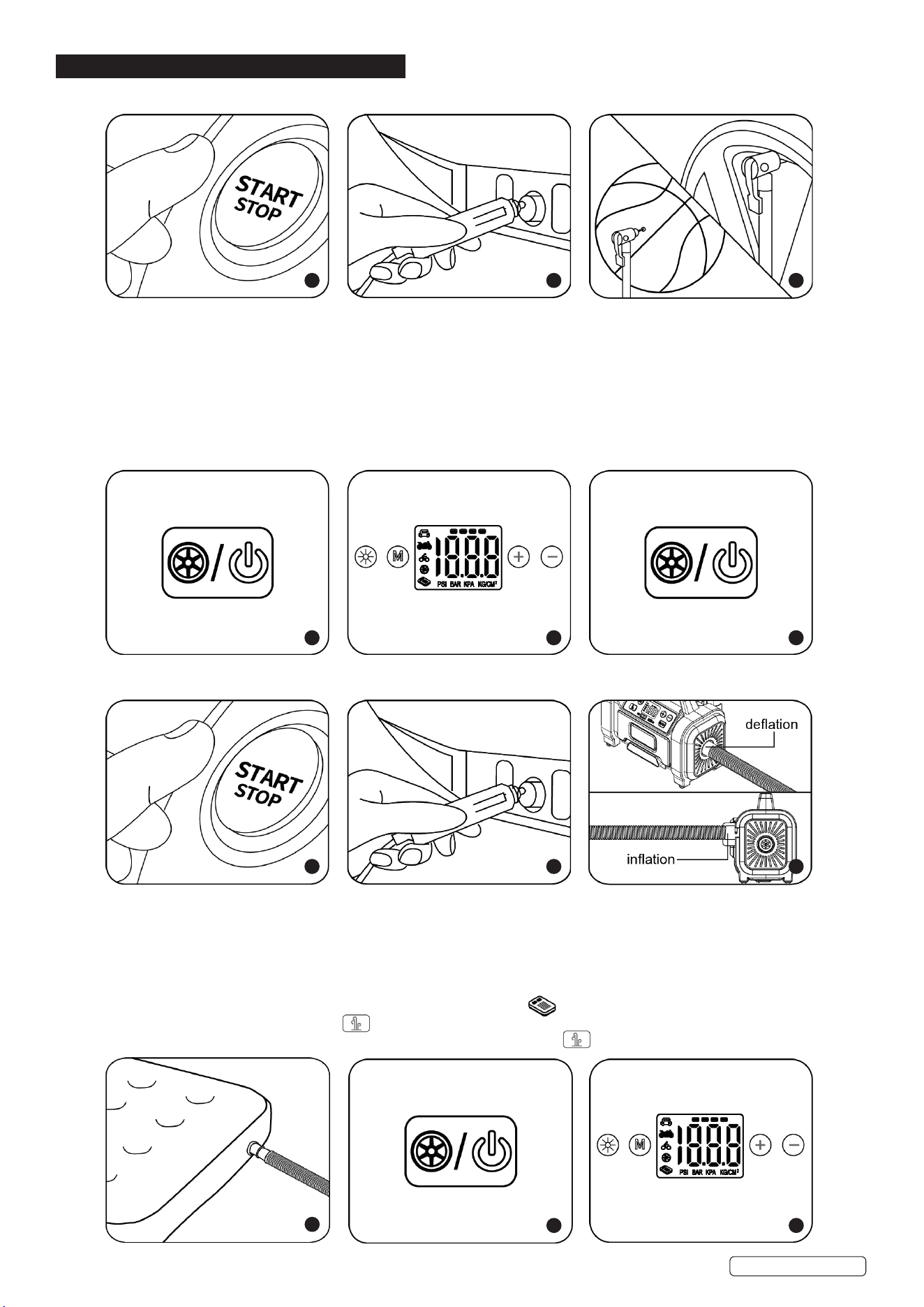
5.1. HIGH PRESSURE ITEMS 12V DC POWER SUPPLY
Step 1. Start the car engine before plugging in the power cord.
Step 2. Plug the power cord into the DC socket.
Step 3. Attach the universal inating valve adaptor to the item, using the clip to lock into place.
Step 4. Press and hold the power On/O button to start the power supply.
Step 5. Press the “M” button to select the display unit, then press “-” or “+” to set the desired pressure.
Step 6. Select the ination mode button the air pump will automatically start.
Step 7. The air pump will automatically stop inating once the preset pressure is reached.
NOTE: Press the “LED” button to select the torch function, choose between the LED light remaining on, or red ashing for the red SOS
function.
5.2. LOW PRESSURE ITEMS 12V DC POWER SUPPLY
Step 1. Start the car engine before plugging in the power cord.
Step 2. Plug the power cord into the DC socket.
Step 3. For deation, connect the high volume hose to the air pumps’s air inlet. For ination, connect the high-volume hose to the air
pumps air outlet, and twist the hose to lock in place.
Step 4. Connect the high volume hose to the low pressure product. (if the inating nozzles are required, install correctly before use).
Step 5. Press and hold the On/O button to start the power supply.
Step 6. Press the “M” button to select the ination mode, and then select mode.
Step 7. Press the ination mode button. The air pump will automatically start.
Step 8. When the desired pressure is reached, it is important to manually press to turn o the air pump.
1 2 3
4 5 6
1 2 3
4
5 6
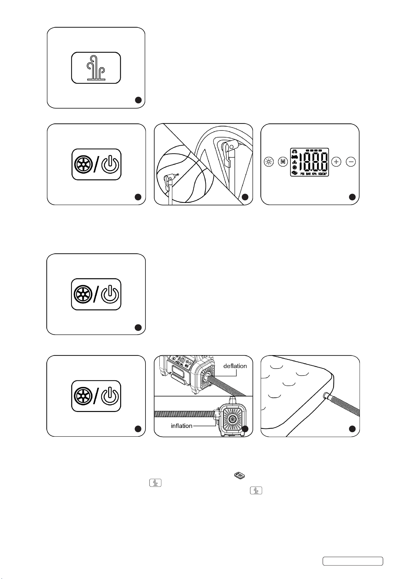
6.1. LI-BATTERY POWER SUPPLY-HIGH PRESSURE ITEMS
Step 1. Press and hold the switch to start the power supply.
Step 2. Attach the universal inating valve adaptor to the item, using the clip to lock into place.
Step 3. Press the “M” button to select the display unit, then press “-” or “+” to set the desired pressure.
Step 4. Select the ination mode button the air pump will automatically start.
Step 5. The air pump will automatically stop inating once the preset pressure is reached.
6.2. LI-BATTERY POWER SUPPLY-LOW PRESSURE ITEMS
Step 1. Press and hold the switch to start the power supply.
Step 2. For deation, connect the high volume hose to the air pumps’s air inlet. For ination, connect the high-volume hose to the air
pumps air outlet, and twist the hose to lock in place.
Step 3. Connect the high volume hose to the low pressure product. (if the inating nozzles are required, install correctly before use).
Step 4. Press the “M” button to select the ination mode, and then select mode.
Step 5. Press the ination mode button. The air pump will automatically start.
Step 6. When the desired pressure is reached, it is important to manually press to turn o the air pump.
Original Language Version
© Jack Sealey Limited
MAC13DR Issue:2 20/03/25
7
1 2 3
4
1 2 3
Original Language Version
© Jack Sealey Limited
MAC13DR Issue:2 20/03/25
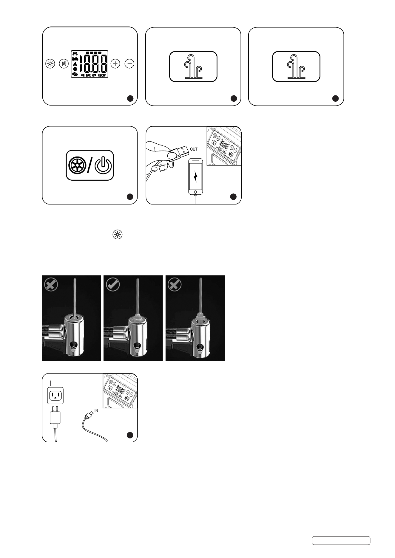
6.3. USB OUTPUT FUNCTION
Step 1. Press and hold the switch to start the power supply.
Step 2. Plug USB into output to charge devices.
6.4. LED FUNCTION
Press the LED light button to select the LED light function, choose between ON, red ashing and red SOS function red.
6.5. BALL INFLATION
6.6. Make sure the needle adaptor is inserted correctly. (See illustrations below for reference).
6.7. Press the “M” button to select the ball mode, select the desired pressure, press ination button (monitor ball pressure and remove
needle if excessive pressure is reached).
NOTE: 100PSI=689.47KPA=6.89BAR
6.8. CHARGING THE BATTERY
6.9. Use the supplied USB cable to re-charge your inator, charge time is 3-5hrs depending on the state of the battery, other functions are
disabled during the charging process.
6.10. Charge the device for 5-7hrs before initial use. After the initial charge, the battery will take about 4-5hrs to achieve a full charge.
6.11. To keep the battery at optimum operating levels we recommend recharging the unit every 3 months.
6.12. During charging, the battery symbol will ash continually on the unit. When fully charged, the battery symbol will display a full charge.
4 5
1 2
1
For reference only
6
Sealey Group, Kempson Way, Suffolk Business Park, Bury St Edmunds, Suffolk. IP32 7AR
01284 757500 sales@sealey.co.uk www.sealey.co.uk
WEEE REGULATIONS
Dispose of this product at the end of its working life in compliance with the EU Directive on Waste Electrical and Electronic
Equipment (WEEE). When the product is no longer required, it must be disposed of in an environmentally protective way. Contact
your local solid waste authority for recycling information.
NOTE: It is our policy to continually improve products and as such we reserve the right to alter data, specications and component parts
without prior notice. Please note that other versions of this product are available. If you require documentation for alternative versions, please
email or call our technical team on technical@sealey.co.uk or 01284 757505.
IMPORTANT: No Liability is accepted for incorrect use of this product.
WARRANTY: Guarantee is 12 months from purchase date, proof of which is required for any claim.
ENVIRONMENT PROTECTION
Recycle unwanted materials instead of disposing of them as waste. All tools, accessories and packaging should be
sorted, taken to a recycling centre and disposed of in a manner which is compatible with the environment. When
the product becomes completely unserviceable and requires disposal, drain any uids (if applicable) into approved
containers and dispose of the product and uids according to local regulations.
BATTERY REMOVAL
Remove the screws in the back section of the tyre inflator section to remove the batteries.
Under the Waste Batteries and Accumulators Regulations 2009, Jack Sealey Ltd are required to inform potential purchasers of products
containing batteries (as defined within these regulations), that they are registered with Valpak’s registered compliance scheme. Jack
Sealey Ltd’s Batteries Producer Registration Number (BPRN) is BPRN00705.
Original Language Version
© Jack Sealey Limited
MAC13DR Issue:2 20/03/25
7. MAINTENANCE
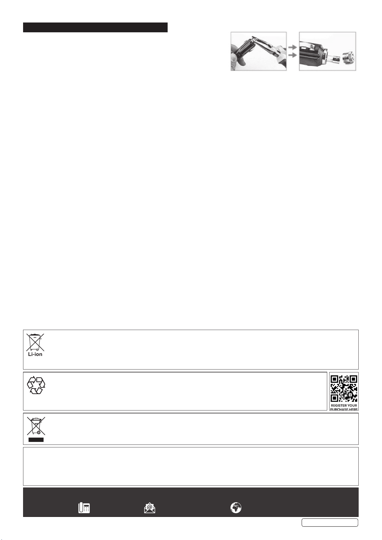
7.1. HOW TO REPLACE A FUSE IN THE 12V PLUG
7.1.1. Unscrew the top of the plug using a pair of long nose pliers.
7.1.2. Remove the fuse.
7.1.3. Insert a new fuse.
7.1.4. Screw the top plug back into socket.
7.2. GENERAL
7.2.1. Keep the device in a dry location and out of the reach of children. This helps prevent device damage and possible personal injuries.
7.3. CLEANING
7.3.1. Clean the surfaces with a soft cloth.
7.4. END OF SERVICE
7.4.1. Through years of normal wear, the tyre inator will eventually become unserviceable. When this happens ensure that it is disposed of in
accordance with local authority regulations.
7.5. BATTERY DISPOSAL
7.5.1. Exposure to high temperatures can cause the batteries to explode; DO NOT dispose of in a re. Some countries have regulations
concerning battery disposal. Follow all applicable regulations. Return used batteries to a collection location for recycling.