RED
+12v constant wire (12v positive input) connect to a 12v constant,
30 A fuse built in.
BLACK Ground wire, important connect to a ground.
RED/BLACK
PINK Siren wire connect to siren, do not require a relay if siren under 3A is used.
INTRODUCTION
ALARM
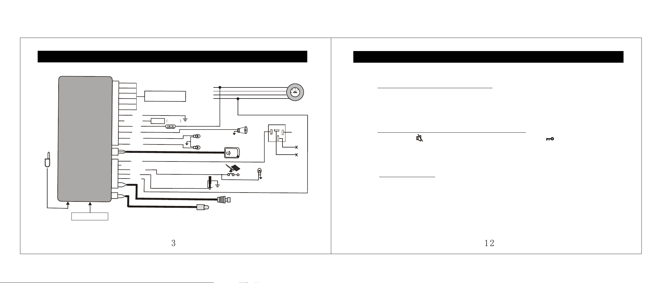
WIRING DESCRITION
The newest technological are integrated in our Two way alarm system. They are fully
programmable for your customers to have personalized security and comfort. The ultimate
in comfort and protection.
The alarm integrated in the system is a fully programmable unit with multi zone protection
such as shock sensor, starter kill output, control power locks and much more.
BROWN Parking light wire (12v positive output) connect to parking light wire
BROWN Parking light wire (12v positive output) connect to parking light wire
12PIN CONNECTION
Trunk Release
FEATURES AND OPERATIONS
button panic mode is engaged. The siren will be chirp 2
seconds and parking light will flashing 3 times.
IGNITION LOCK:
Door locks automatically when ignition is ON and brake pedal is depressed after driving 15
seconds. Doors will unlock when ignition is turned off.
SHOCK SENSOR PRE-WARNING:
Siren chirps rapidly when shock sensor is trigger. If shock sensor is trigger for a second
time within 10 seconds, the siren will sounds for 30 seconds.
PANIC MODE:
While arming mode press
WIRING DESCRITION
ORANGE Lock NC (See page 4)
WHITE Lock COM (See page 4)
YELLOW Lock NO (See page 4)
12PIN CONNECTION
7PIN CONNECTION
ORANGE/
Unlock NC (See page 4)
BLACK
WHITE/
Unlock COM (See page 4)
BLACK
YELLOW/
Unlock NO (See page 4)
BLACK
YELLOW Starter kill wire (500ma negative output) connect to starter kill relay.
NOT USED
ORANGE
Brake wire (positive input) connect to the switched side of the brake pedal
switch.
BLUE Door trigger negative input, connect to negative door switch.
WHITE Switched ignition input (12v positive input) connect to ignition wire.
BLACK For reset switch
RED For reset switch
ARMING:
Arming the system will also enable the starter kill and unlock the door, if installed.
PASSIVE ARMING:
The system will automatically arm without door lock itself 30 seconds after the ignition has
been turned OFF and the last door closed.
DISARMING:
Disarming the system will also disable the stater kill and unlock the door, if installed.
SAFE REARMING:
If you disarm the system by accident and you do not open any access (door ), it will rearm
automatically after 30 seconds, unless the engine running.
STARTER KILL OUTPUT:
When the system is armed manually or via passive arming the starter kill will arm at the
same time.
FEATURES AND OPERATIONS
WIRE CONNECTION GUIDE
Shock sensor
O
N
O
N
ACCA
C
C
START
S
T
A
R
T
OFFO
F
F
O
N
O
N
Lo
L
o
Hi
H
i
Black
Red/black
Red
CENTRAL DOORS
LOCK CONNECTION
Pink
Brown
Brown
Yellow
Orange
Blue
White
Reset switch
Parking light
Siren
P12
P3
P7
P2
R
L
option
Antenna
Trunk
Learning button
Door trigger negative input
Brake switch (positive input)
Battery
Starter
Accessories
Ignition
Ground
+12V
Starter wire
87
86
30
85
STEP1
DELETE CODE FOR CONTROL UNIT:
Press learning button at control unit until the LED at control unit (near the learning
button) turn off. System will delete all transmitter code.
STEP2
DELETE CODE FOR TWO WAY TRANSMITTER:
Press button at two way transmitter for 8 seconds until icon at LCD display
turn off, transmitter will delete control unit code.
STEP3
CODE LEARNING:
Press learning button at control unit, LED at control unit (near the Learning button)
will flash once to enter code learning mode. Press any Button on the transmitter,
LED will turn on 0.5 second when received the transmitter code. Continuous doing
the same step for the next transmitter.
NOTE: The transmitter supplied is already programmed to the system.
TRANSMITTER CODE LEARNING
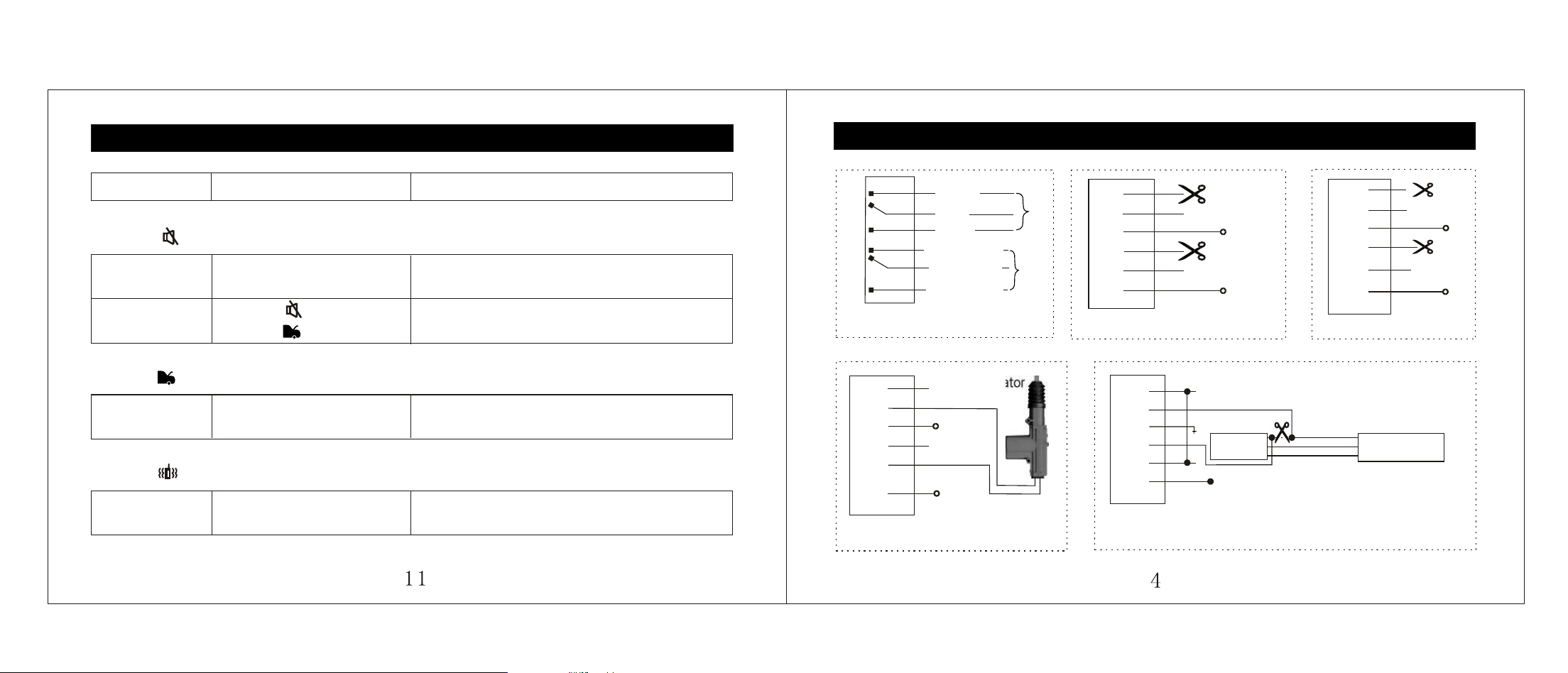
(AUDI) (BENZ)100
1
2
3
2.Negative trigger2.Negative trigger
NOTE: The system must be programmed for
4 second door lock pulses.
NOTE: The system must be programmed for
4 second door lock pulses.
To the
door
+12V
(-)
(-)
+12V
+12V
Actuator
Adding actuatorAdding actuator
NC
COM
NC
NC
NC
NC
COM
COM
COM
COM
NC
COM
NC
NC
NC
NC
COM
COM
COM
COM
NO
NO
NO
NO
NO
NO
NO
NO
NO
NO
Lock
Lock
Unlock Unlock
+12V
+12V
Interior circuit diagram of the relayInterior circuit diagram of the relay
1.Positive trigger
1.Positive trigger
Orange
Lock
Unlock
white
yellow
Orange/black
white/black
yellow/black
To electric
vacuum pump
(-)
(-)
DOOR LOCK WIRING DIAGRAM
Vacuum system
TRANSMITTER OPERATION
FUNCTION
PRESSING BUTTON
ACTIVATION
BUTTON ARM SILENTLY
ARMING NO
CHIRP
Press once
Press once
System armed and doors locked
without chirp
ANTI CAR-
HIJACKING
Press then
press
while driving.
System enter anti car-hijacking mode.
BUTTON TRUNK RELEASE
TRUNK
RELEASE
Trunk will release.
BUTTON
VIBRATION (For two way transmitter)
VIBRATION
Press once
To select vibration on or off.
IMPORTANT: The installation must be complete before accessing programming
mode.
DOOR LOCK PULSE:
Some European Vehicles such as Mercedes-Benz and Audi, require longer lock and unlock
pulse to operate the vacuum pump.
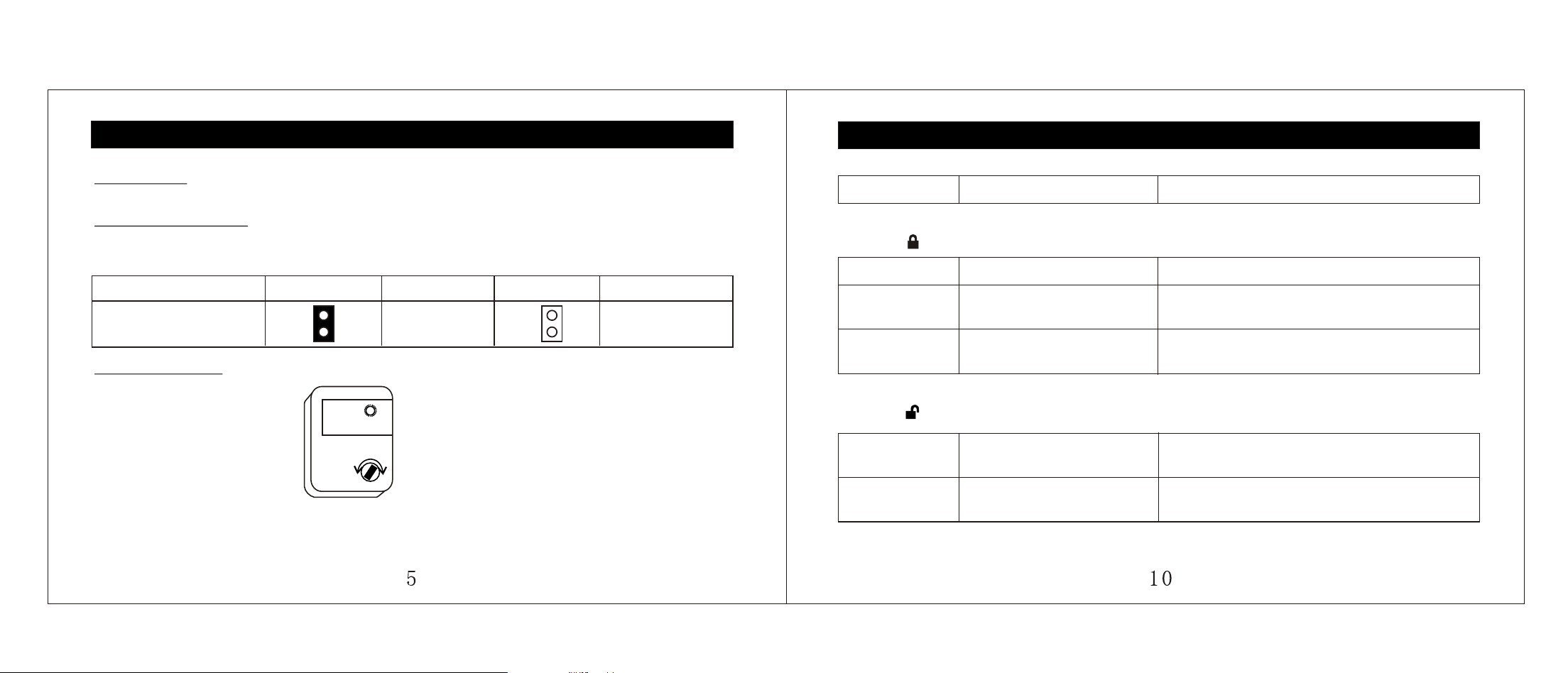
SHOCK SENSOR:
NOTE: When adjusting the sensor, it must be in the same mounting location that it will be
after the install is complete. Adjusting the sensor and then relocating the shock
sensor requires readjustment.
PROGRAMING
SHOCK
SENSOR
Max
FUNCTION
PRESSING BUTTON
ACTIVATION
BUTTON
ARM:
ARMING Press once System armed and doors locked with chirp.
STOP ENGINE
Press once (when engine
running with engine start).
Send signal to stop engine.
PANIC MODE
Press once after system
arm 30 seconds.
Siren chirps 2 seconds and parking light
flashing 3 times.
BUTTON
DISARM
DISARMING
Press once
System disarmed and doors unlocked
with 2 chirp.
DISARMING
NO CHIRP
Press once when system
arm at silently mode.
System disarmed and doors unlocked
without chirp.
TRANSMITTER OPERATION
DOOR LOCK
PULSE
JUMPER
MODE
FUNCTION
MODE
FUNCTION
4SEC
0.5SEC
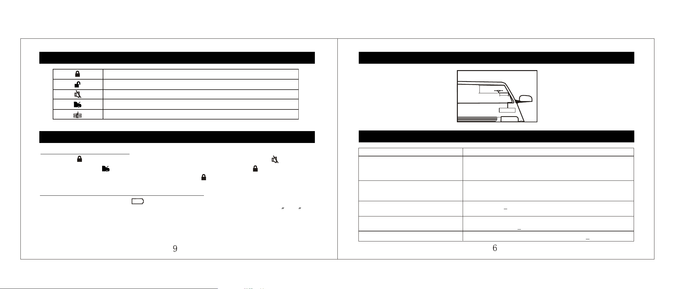
ANTENNA INSTALLATION POINTS
TROUBLESHOOTING
5-10cm
5-10cm
MainframeMainframe
Antenna frequency
head location
TROUBLE SHOOT
1. Siren chirp continuously cannot be
deactivating by transmitter after the
installation of the control module.
1A. Please check if the electrical outlets are mistakenly plugged
Problem with the connection
Fuse of control module blow
Is the main module matched with the transmitter?
5A. Please check the connection see page 4
.
2. When the alarm is triggered the
siren does not actives.
2A. Please check if there is something wrong with the
siren, check the connection between main unit and
siren.
3. Status LED doesn't work.
3A. See page 3
Is the LED plugged into the correct
socket?
4. Door locks operate backwards.
4A. This unit has easily-reversed lock/unlock output.
Recheck page 3
to see if you have reverse these.
5. Door locks doesn't work.
COMMOM BUTTON USED BY 3508 AND 3309 TRANSMITTER
ARM & LOCK THE DOORS
DISARM & UNLOCK THE DOORS
ARM & LOCK THE DOOR SIRENTLY
TRUNK RELEASE
VIBRATION ON/OFF (For two way transmitter)
ADJUST REALTIME CLOCK:
Keep press
button 8 seconds until the display show the hour flashing. Use button to
adjust hour and use button to adjust minute. When it is done, press button to exit.
NOTE: You can exit a mode anytime by pressing the Button.
TRANSMITTER OPERATION
REPLACE THE BATTERY OF YOUR TRANSMITTER:
icon will flashing at display and you hear beeps sound.
Transmitter battery has to be change. Your two way transmitter is powered by an AAA 1.5V
alkaline battery and your one way transmitter is powered by two pieces 2016 3V battery.
NOTE: When the battery weekends, operating range will be reduced and the back light will
dim.
When transmitter battery low,
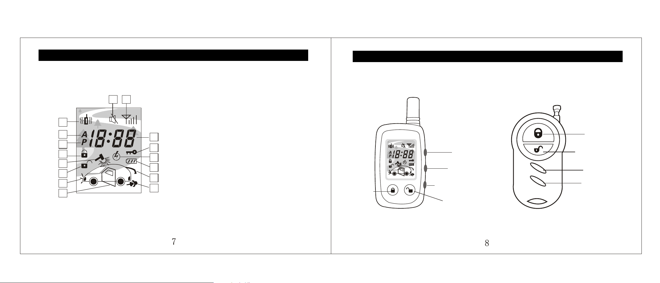
TWO WAY LCD TRANSMITTER OPERATION
12
3
11
12
13
14
15
4
5
6
7
8
9
10
16
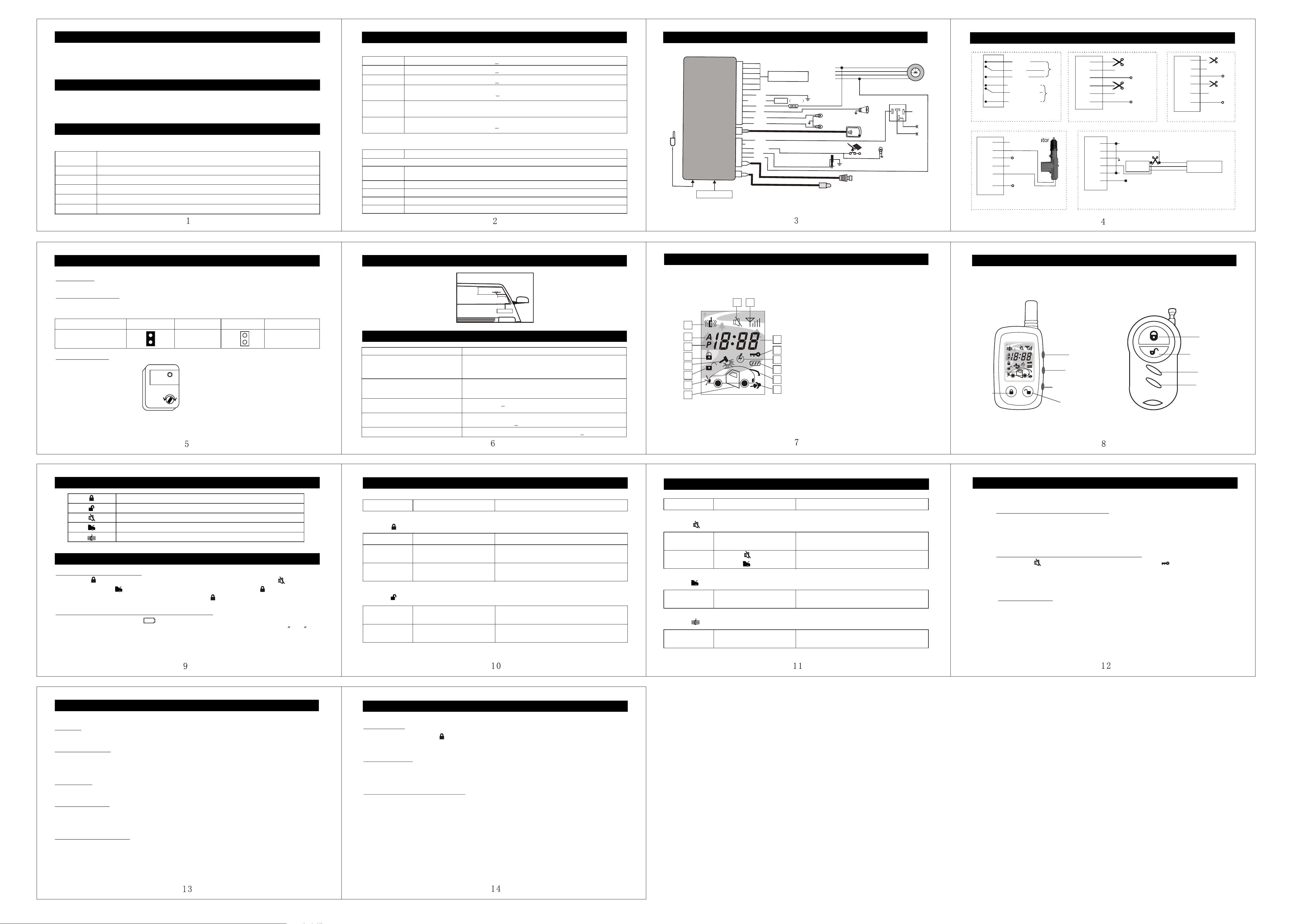
TRANSMITTER OPERATION
Two Way Transmitter One Way Transmitter
LOCK
LOCK
UNLOCK
UNLOCK
MUTE
MUTE
TRUNK
TRUNK
VIBRATION
TWO-WAY
1. R transmit / Receive
2. Silent mode
3. Vibration mode
4. AM
5. PM
6. Lock
7. Impact detector alarm
8. Unlock
9. Parking light
10. Door open
11. Time display
12. Successful learning indicator
13. Engine start
14. Low battery indicator
15. Trunk release
16. Engine running
F
(AUDI) (BENZ)100
1
2
3
2.Negative trigger2.Negative trigger
NOTE: The system must be programmed for
4 second door lock pulses.
NOTE: The system must be programmed for
4 second door lock pulses.
To the
door
+12V
(-)
(-)
+12V
+12V
Actuator
Adding actuatorAdding actuator
NC
COM
NC
NC
NC
NC
COM
COM
COM
COM
NC
COM
NC
NC
NC
NC
COM
COM
COM
COM
NO
NO
NO
NO
NO
NO
NO
NO
NO
NO
Lock
Lock
Unlock Unlock
+12V
+12V
Interior circuit diagram of the relayInterior circuit diagram of the relay
1.Positive trigger
1.Positive trigger
Orange
Lock
Unlock
white
yellow
Orange/black
white/black
yellow/black
To electric
vacuum pump
(-)
(-)
DOOR LOCK WIRING DIAGRAM
Vacuum system
WIRE CONNECTION GUIDE
Shock sensor
ONO
N
ACCA
C
C
STARTS
T
A
R
T
O
FF
O
F
F
ONO
N
LoL
o
Hi
H
i
Black
Red/black
Red
CENTRAL DOORS
LOCK CONNECTION
Pink
Brown
Brown
Yellow
Orange
Blue
White
Reset switch
Parking light
Siren
P12
P3
P7
P2
R
L
option
Antenna
Trunk
Learning button
Door trigger negative input
Brake switch (positive input)
Battery
Starter
Accessories
Ignition
Ground
+12V
Starter wire
87
86
30
85
WIRING DESCRITION
ORANGE Lock NC (See page 4)
WHITE Lock COM (See page 4)
YELLOW Lock NO (See page 4)
12PIN CONNECTION
7PIN CONNECTION
ORANGE/
Unlock NC (See page 4)
BLACK
WHITE/
Unlock COM (See page 4)
BLACK
YELLOW/
Unlock NO (See page 4)
BLACK
YELLOW Starter kill wire (500ma negative output) connect to starter kill relay.
NOT USED
ORANGE
Brake wire (positive input) connect to the switched side of the brake pedal
switch.
BLUE Door trigger negative input, connect to negative door switch.
WHITE Switched ignition input (12v positive input) connect to ignition wire.
BLACK For reset switch
RED For reset switch
RED
+12v constant wire (12v positive input) connect to a 12v constant,
30 A fuse built in.
BLACK Ground wire, important connect to a ground.
RED/BLACK
PINK Siren wire connect to siren, do not require a relay if siren under 3A is used.
INTRODUCTION
ALARM
WIRING DESCRITION
The newest technological are integrated in our Two way alarm system. They are fully
programmable for your customers to have personalized security and comfort. The ultimate
in comfort and protection.
The alarm integrated in the system is a fully programmable unit with multi zone protection
such as shock sensor, starter kill output, control power locks and much more.
BROWN Parking light wire (12v positive output) connect to parking light wire
BROWN Parking light wire (12v positive output) connect to parking light wire
12PIN CONNECTION
Trunk Release
FEATURES AND OPERATIONS
button panic mode is engaged. The siren will be chirp 2
seconds and parking light will flashing 3 times.
IGNITION LOCK:
Door locks automatically when ignition is ON and brake pedal is depressed after driving 15
seconds. Doors will unlock when ignition is turned off.
SHOCK SENSOR PRE-WARNING:
Siren chirps rapidly when shock sensor is trigger. If shock sensor is trigger for a second
time within 10 seconds, the siren will sounds for 30 seconds.
PANIC MODE:
While arming mode press
ARMING:
Arming the system will also enable the starter kill and unlock the door, if installed.
PASSIVE ARMING:
The system will automatically arm without door lock itself 30 seconds after the ignition has
been turned OFF and the last door closed.
DISARMING:
Disarming the system will also disable the stater kill and unlock the door, if installed.
SAFE REARMING:
If you disarm the system by accident and you do not open any access (door ), it will rearm
automatically after 30 seconds, unless the engine running.
STARTER KILL OUTPUT:
When the system is armed manually or via passive arming the starter kill will arm at the
same time.
FEATURES AND OPERATIONS
STEP1
DELETE CODE FOR CONTROL UNIT:
Press learning button at control unit until the LED at control unit (near the learning
button) turn off. System will delete all transmitter code.
STEP2
DELETE CODE FOR TWO WAY TRANSMITTER:
Press button at two way transmitter for 8 seconds until icon at LCD display
turn off, transmitter will delete control unit code.
STEP3
CODE LEARNING:
Press learning button at control unit, LED at control unit (near the Learning button)
will flash once to enter code learning mode. Press any Button on the transmitter,
LED will turn on 0.5 second when received the transmitter code. Continuous doing
the same step for the next transmitter.
NOTE: The transmitter supplied is already programmed to the system.
TRANSMITTER CODE LEARNING
TRANSMITTER OPERATION
FUNCTION
PRESSING BUTTON
ACTIVATION
BUTTON ARM SILENTLY
ARMING NO
CHIRP
Press once
Press once
System armed and doors locked
without chirp
ANTI CAR-
HIJACKING
Press then
press
while driving.
System enter anti car-hijacking mode.
BUTTON TRUNK RELEASE
TRUNK
RELEASE
Trunk will release.
BUTTON
VIBRATION (For two way transmitter)
VIBRATION
Press once
To select vibration on or off.
FUNCTION
PRESSING BUTTON
ACTIVATION
BUTTON
ARM:
ARMING Press once System armed and doors locked with chirp.
STOP ENGINE
Press once (when engine
running with engine start).
Send signal to stop engine.
PANIC MODE
Press once after system
arm 30 seconds.
Siren chirps 2 seconds and parking light
flashing 3 times.
BUTTON
DISARM
DISARMING
Press once
System disarmed and doors unlocked
with 2 chirp.
DISARMING
NO CHIRP
Press once when system
arm at silently mode.
System disarmed and doors unlocked
without chirp.
TRANSMITTER OPERATION
COMMOM BUTTON USED BY 3508 AND 3309 TRANSMITTER
ARM & LOCK THE DOORS
DISARM & UNLOCK THE DOORS
ARM & LOCK THE DOOR SIRENTLY
TRUNK RELEASE
VIBRATION ON/OFF (For two way transmitter)
ADJUST REALTIME CLOCK:
Keep press
button 8 seconds until the display show the hour flashing. Use button to
adjust hour and use button to adjust minute. When it is done, press button to exit.
NOTE: You can exit a mode anytime by pressing the Button.
TRANSMITTER OPERATION
REPLACE THE BATTERY OF YOUR TRANSMITTER:
icon will flashing at display and you hear beeps sound.
Transmitter battery has to be change. Your two way transmitter is powered by an AAA 1.5V
alkaline battery and your one way transmitter is powered by two pieces 2016 3V battery.
NOTE: When the battery weekends, operating range will be reduced and the back light will
dim.
When transmitter battery low,
TWO WAY LCD TRANSMITTER OPERATION
12
3
11
12
13
14
15
4
5
6
7
8
9
10
16
1. R transmit / Receive
2. Silent mode
3. Vibration mode
4. AM
5. PM
6. Lock
7. Impact detector alarm
8. Unlock
9. Parking light
10. Door open
11. Time display
12. Successful learning indicator
13. Engine start
14. Low battery indicator
15. Trunk release
16. Engine running
F
ANTENNA INSTALLATION POINTS
TROUBLESHOOTING
5-10cm
5-10cm
MainframeMainframe
Antenna frequency
head location
TROUBLE SHOOT
1. Siren chirp continuously cannot be
deactivating by transmitter after the
installation of the control module.
1A. Please check if the electrical outlets are mistakenly plugged
Problem with the connection
Fuse of control module blow
Is the main module matched with the transmitter?
5A. Please check the connection see page 4
.
2. When the alarm is triggered the
siren does not actives.
2A. Please check if there is something wrong with the
siren, check the connection between main unit and
siren.
3. Status LED doesn't work.
3A. See page 3
Is the LED plugged into the correct
socket?
4. Door locks operate backwards.
4A. This unit has easily-reversed lock/unlock output.
Recheck page 3
to see if you have reverse these.
5. Door locks doesn't work.
IMPORTANT: The installation must be complete before accessing programming
mode.
DOOR LOCK PULSE:
Some European Vehicles such as Mercedes-Benz and Audi, require longer lock and unlock
pulse to operate the vacuum pump.
SHOCK SENSOR:
NOTE: When adjusting the sensor, it must be in the same mounting location that it will be
after the install is complete. Adjusting the sensor and then relocating the shock
sensor requires readjustment.
PROGRAMING
SHOCK
SENSOR
Max
DOOR LOCK
PULSE
JUMPER
MODE
FUNCTION
MODE
FUNCTION
4SEC
0.5SEC
TRANSMITTER OPERATION
Two Way Transmitter
LOCK
UNLOCK
MUTE
TRUNK
VIBRATION
TWO-WAY
One Way Transmitter
LOCK
UNLOCK
MUTE
TRUNK