
1
Installation Guide
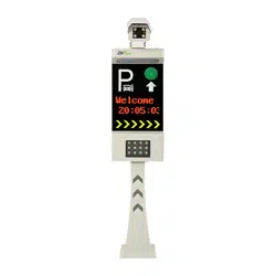
License Plate Recognition Integrated Machine
Version: 1.0
Date: May, 2017
1
1. Installation Tools
Inner hexagon spanner, ground drill (the latter is not delivered with the product).
2. Safety Precautions
Carefully read this installation guide before installing and using the product. After the installation is
complete, strictly check the terminal connection according to the wiring terminal diagram.
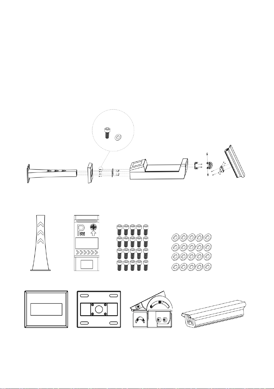
3. Structure
4. Parts List
5. Installation Location
A
B
C
D
F
E
G
H
A
Base support F Upper device body C M6 screws
D
Shim
B Base cover
E
Metal sheet for fixing
G Cardan joint
H
Camera

2
It is important for the integrated machine to quickly and accurately output license plate recognition
results and capture high-quality license plate pictures. Therefore, the installation location of the
integrated machine aims to ensure that complete and clear license plate pictures are captured.
Installation on a straight lane
A straight lane is an ideal installation environment for capturing high-quality pictures when vehicles
move to the recognition area.
1) The integrated machine and the barrier gate can be installed on the same side of the lane but
the integrated machine must be installed in front of the barrier gate with the gap of no less
than 30cm, so as to avoid mutual interference.
2) When video recognition is adopted, the optimal distance between the recognition area and
the integrated machine is 3.5~4m.
3) When video and ground sense recognition is adopted, the optimal distance between the
ground coil and the integrated machine is 3.5~4m.
Installation on a broad lane
1) If a lane is too broad, the moving directions of vehicles are not straight and vehicle heads may
lean left or right, which may affect the recognition effect. You can divide the lane into two
lanes or use barriers such as cone buckets or road piles to mark out a non-motor vehicle lane
so that the motor vehicle lane becomes narrow and the vehicle movement direction is
straight.
2) If a lane is too board but cannot be divided into two lanes or no non-motor vehicle lane can
be marked out, for this situation, we can install two cameras, that is, install one camera on
each side of the lane. In this way, license plates can be captured and recognized no matter
whether vehicles lean left or right.
3) If a lane is very short, vehicles usually lean to one side when they move from one direction. In
this case, install the camera on the side to which the vehicle heads lean. Then, the vehicle
heads face right the camera. When vehicles can move from both directions, install one
camera in each direction to capture license plate pictures.
Installation on a curve lane
When the device is installed on a curve lane, vehicles move to the external side of the curve.
Therefore, the integrated machine shall be installed on the external side of the curve. In this way,
when vehicles move to the recognition area, the camera can capture the front view of the license
plates.
Installation in an underground garage
When installing the integrated machine in an underground garage, follow the principle below:
1) Entrance: Install the integrated machine on the horizontal road above the ramp of the
underground garage.
2) Exit: Install the integrated machine on the horizontal road below the ramp of the
underground garage.
In this way, when the integrated machine fails to recognize a license plate and the barrier gate
cannot be opened, the vehicle will not stop on the ramp of the underground garage.
3
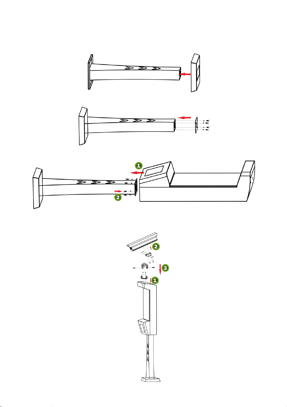
6. Installation Procedure
1) Insert the base cover into the base support.
2) Fix the metal sheet for fixing on the base support and install the screws (with
Shim).
3) Fasten the upper device body on the base support and install the screws (with
Shim).
4) Erect the entire body and install it at the installation position for fixing.
5) Fasten the cardan joint and install the camera.
A
B
E
D
C
F
G
H
4
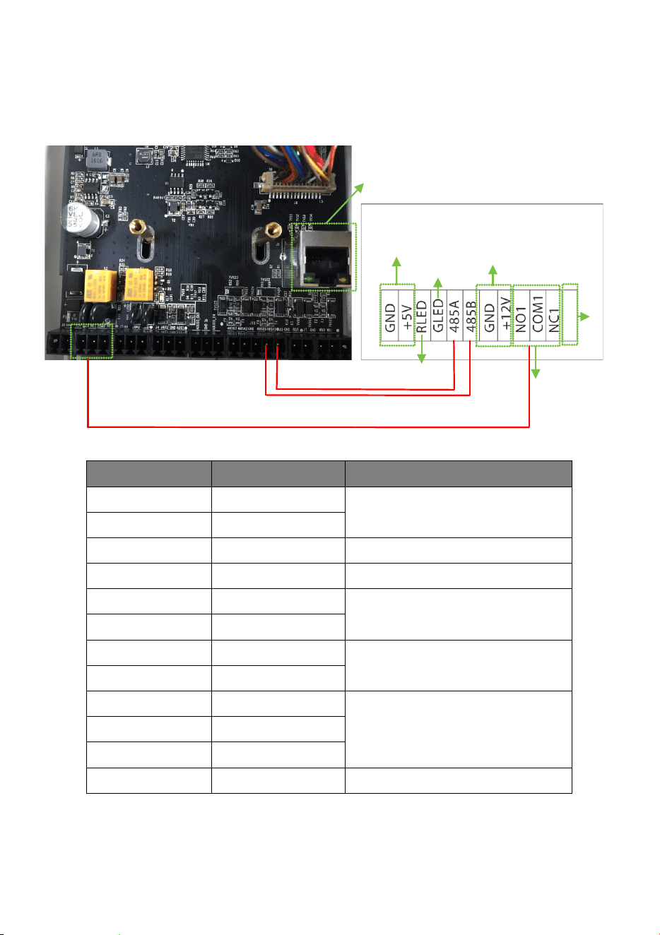
7. Cable Connection Description
1) Wiring terminal diagram
2) Port description
Pin Wire Usage
GND Black
Power interface of the integrated
machine
+5V Red
RLED Red Red light
GLED Green Green light
485A Green For connecting to the 485A1 and
485B1 ports of the camera
485B White
GND
Black
Power interface of the camera
+12V Red
NO1
Green
Relay output for connecting to the
barrier gate
COM1 Red
NC1 Blue
Reserved
License Plate Recognition
Integrated Machine
485 connection cable
Green light
Red light
Reserved
License Plate Recognition Camera
Ethernet Interface
Relay output for
connecting to the
barrier gate
Power interface of the camera
Power interface of the integrated machine

1


