

Due to the regular upgrades of systems and products, ZKTeco could not guarantee exact consistency between the
actual product and the written information in this manual.
VDP03-B3
Version: 1.0
User Manual
1 Overview
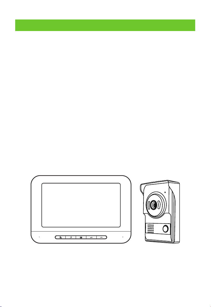
The product is a wired color video intercom doorbell system. The
system is composed of two parts, outdoor unit and indoor unit. The two
units are connected with four-core cables. 15V DC is used for the indoor
unit to realize the functions such as doorbell calling, monitor,
intercommunication, and remote unlocking. Imported TFT-LCD is used
for the display screen to provide clear images,bright and distortionless
colors. A high-definition CMOS camera is used to provide good night
vision effects. The intercom and doorbell are loud and clear. According
to the manual, the effective transmission distance is as long as 100m
(Page 9 of the manual – Wiring Requirements); if it is used with a multi-
door controller, at most four outdoor unit extensions can be extended
to realize the access control for various entrances. It is applicable to
places such as households, villas, apartments, offices, and hospitals.
-1-
1.1 Product Introduction
1.2 Appearance
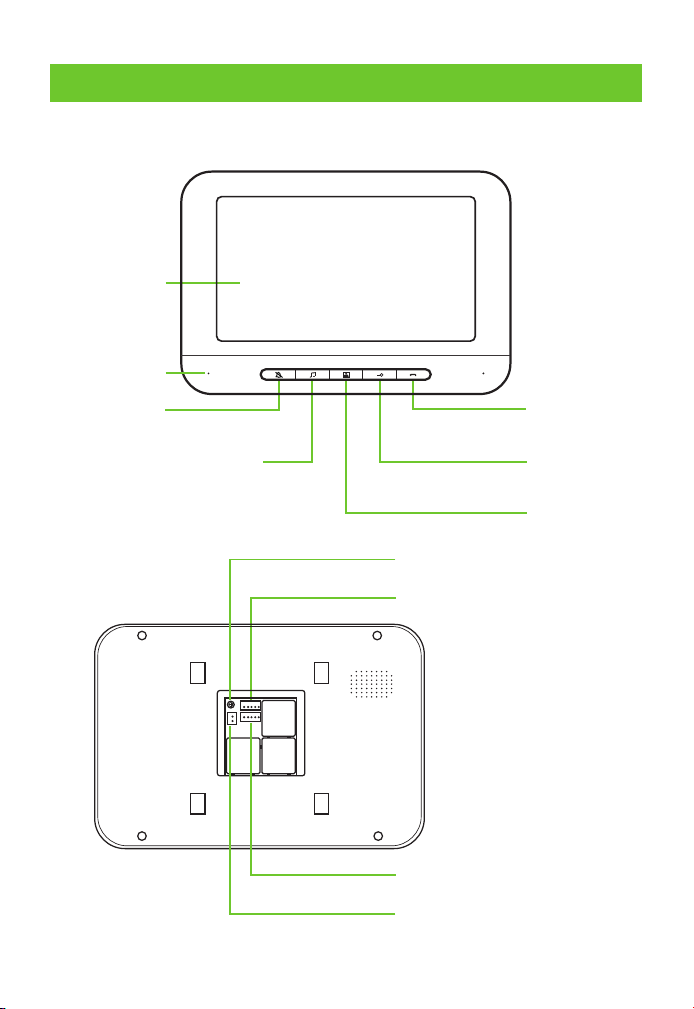
Mute
Adjust the volume of music
& replace the ring tone
Monitor
Unlock
Talk
Color LCD
Microphone
-2-
Connects with an outdoor unit
DC 15V power interface
Connects with next indoor unit
Intercom volume adjustment
2 Outdoor Unit
2.1 Product Function

-3-
2.2 Function of Indoor Unit
2.2.1 Indoor Unit Ringtone Setting
Mute Setting
In the standby mode of the indoor unit, press the button " " first to turn
on the screen, and then press the button " " to turn off the bell and
intercom, making no effects on image display. If it is required to turn on
the bell and intercom,press the button " " again in the monitor " " mode.
N Disturbance-free mode will be activated after the mute ote:
function is enabled.
Change Ringtong
In the standby mode of the indoor unit, press the button " " first to turn on
thescreen, and then press the button " " to activate the ringtone and enter
"change ringtone" settings. The system is equipped with 25 ringtones of various
lengths. The button " " is pressed once to change one ringtone. After a suitable
ringtone is selected, stop pressing the button. The last ringtone will be the
ringtone when the system is called by anyone.
Ringtong Volume Adjustment
In the standby mode of the indoor unit, press the button " " first to turn on
the screen, and then press the button " " to activate the ringtone and enter
"ringtone volume" settings. It has three levels, large, medium and small. Press
the button " " for two seconds each time to increase or decrease the volume
progressively.
N After power-off, all ringtone settings will be restored to ote:
factory settings.
2.2.2 Instructions for Doorbell Operation
When any visitor presses the call button on the outdoor unit, the
indoor unit screen will display the outdoor image in real time and the
bell will ring.
The indoor user may press the button " " to talk with the visitor.
Note: Talking will be enabled by pressing the button " " for the
1.
2.
-4-
button " " for the first time, and it will be disabled if the button is
pressed again. The screen will be off automatically in 30 seconds if
the calling is not answered.
In the intercom mode, the indoor user may press the button " " to
open the door.
In the intercom mode, the indoor user may press the button " " to
finish talking or talking will finish automatically in 90 seconds.
If it is required to resume talking after hang-up, press the button " "
first and then the button " " to talk with the visitor.
In the standby mode of the indoor unit, press the button " " first and
then the button " " to unlock the door; the screen will be off
automatically in 90seconds or it can be powered off by pressing the
button " " once.
3.
4.
5.
6.
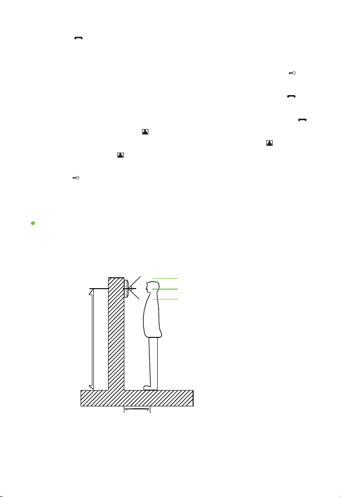
2.3 Instructions for Indoor Unit Installation
150cm-165cm
30cm
About 175cm
Effective range: about 30cm
About 150cm
Vertical effective range
At first, determine the location and height for installing the indoor unit; the
reference height is 150-165cm from the display screen center to ground.
Installation & Location of Indoor Unit
-5-
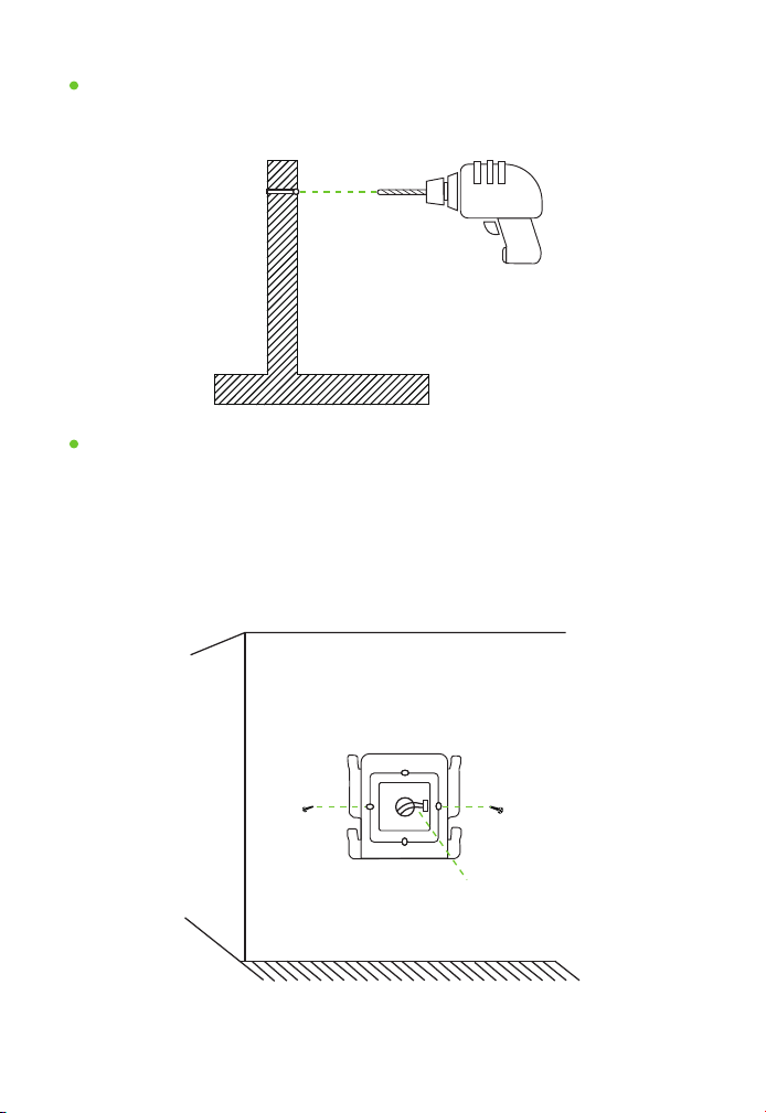
Make a mark and drill a hole after finishing location on the wall.
Make A Mark and Drill a Hole on the Wall
Electric drill
Bore diameter: about 1.5cm
As shown in the figure: Take out the hanging board; open the package
of screws to take out the rubber plug and screws.
1. Drill a hole, bore diameter: about 6mm.
2. Fix the rubber plug at the above hole.
3. Fix the hanging board with screws.
Fix the Indoor Unit Hanging Board
Indoor unit hanging board
Screw
5-core wire
-6-
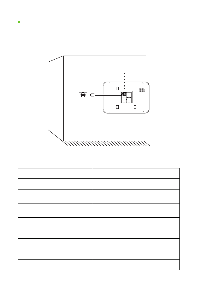
1. Take out the indoor unit and power supply;
2. Insert the power plug and 5-core connector;
3. Horizontally hang the indoor unit on the fixed hanging board.
Fix the Indoor Unit
Indoor unit
Hanging board buckle
15V power supply
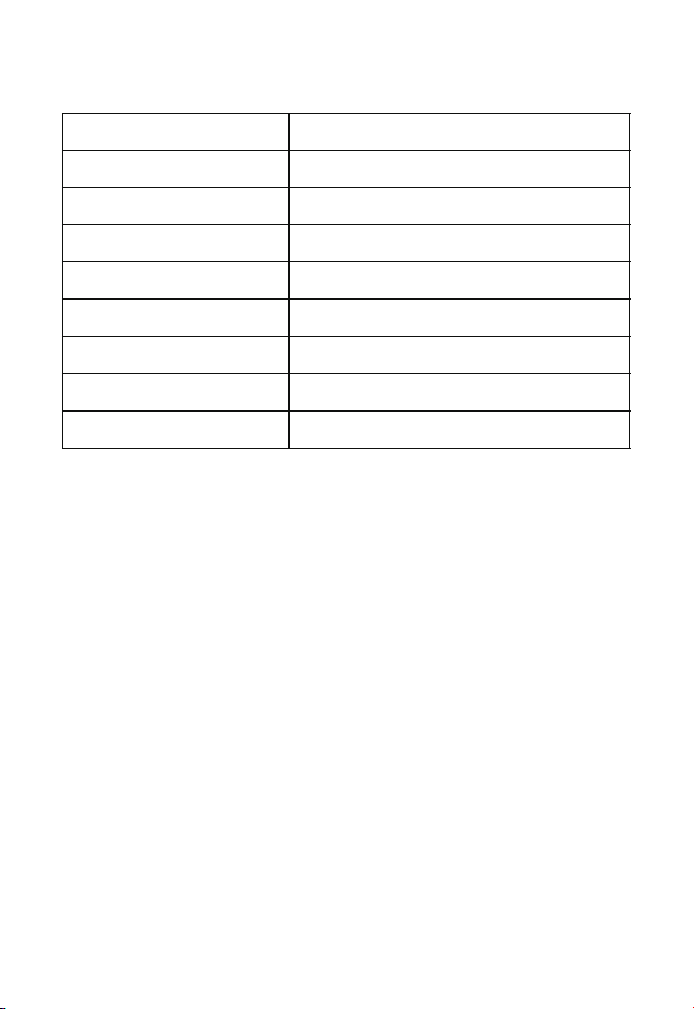
2.4 Pameters of Indoor Unit
Screen
Color HD TFT LCD
Resolution
800*480
Power supply
Input: AC100-240
Output: DC15V 1200mA
Power
Standby: ≤1W
Operating: ≤10W
Wiring terminal
5PX2.54
Operating temperature
-20°C-60°C
Monitoring time
90 seconds
Talking time
90 seconds
Number of calling ringtones
25
-7-
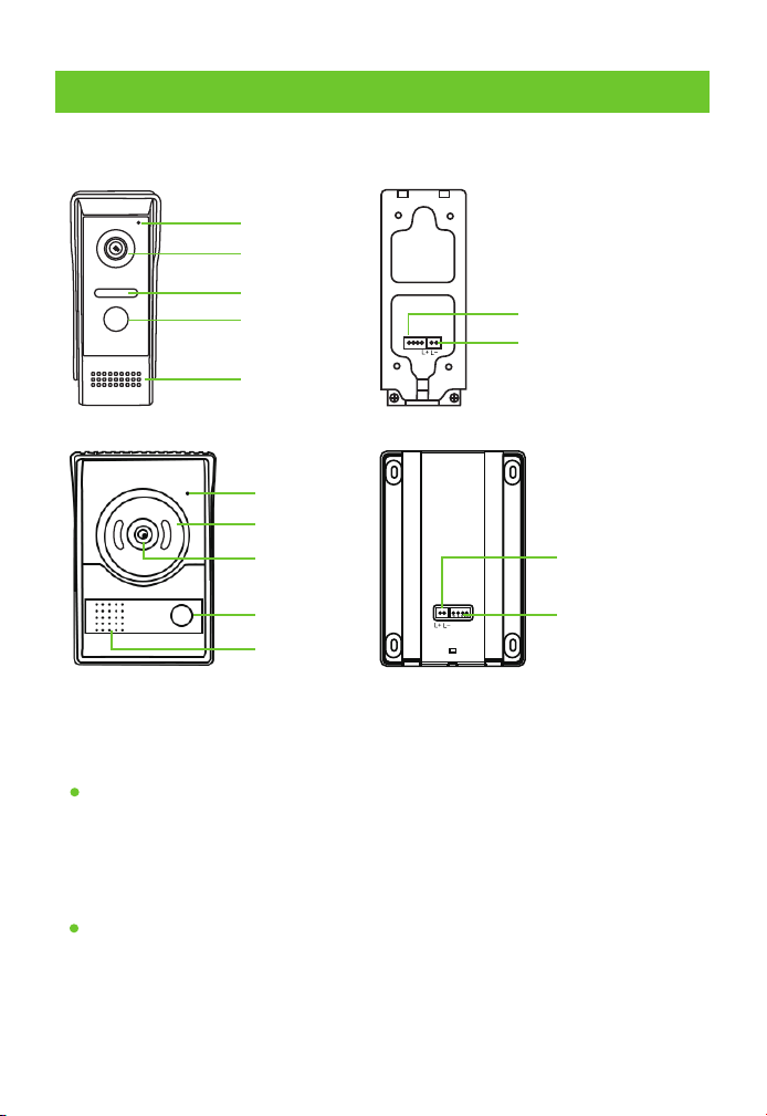
3 Outdoor Unit
3.1 Product Introduction
Microphone
Camera
Infrared night
vision lamp
Call button
Speaker
4P indoor unit
connector socket
2P electronic control
lock connector socket
Microphone
Camera
Infrared night
vision lamp
Call button
Speaker
4P indoor unit
connector socket
2P electronic
control lock
connector socket
3.2 Function of Outdoor Unit
Calling & Intercom
Night Vision
A visitor presses the call button on the outdoor unit to call the indoor
by pressing one key; intercom talking can be made after the indoor
unit is answered.
An infrared or white light night vision lamp is used to clearly see any
visitor one meter away at night.
-8-
Rain Proof
Outdoor Unit Unlocking
Equipped with a rain cover, Ingress protection – level 4, for outdoor uses.
With 12V unlocking voltage signals, it can be directly connected with a
12V electronic control lock. If any other type of electronic control locks
is used, access control power supply with (control +, control-) 12V
terminal control shall be available.
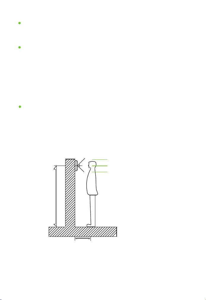
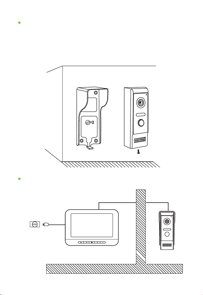
3.3 Instructions for Outdoor Unit Installation
150cm-165cm
30cm
About 175cm
Effective range: about 50cm
About 150cm
Vertical effective range
At first, determine the location and height for installing the outdoor
unit; the reference height is 150-165cm from the outdoor unit center
to ground.
It’s required to avoid installing the outdoor unit at any place with
strong direct sunlight.
Installation & Location of Outdoor Unit
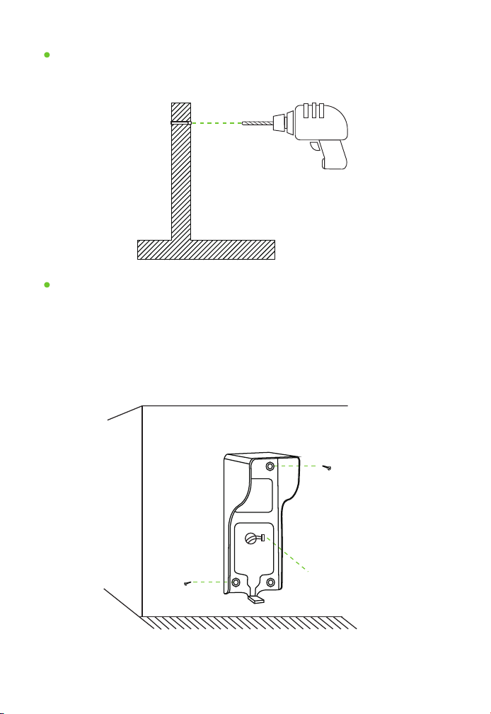
Make a mark and drill a hole after finishing location on the wall.
Make A Mark and Drill a Hole on the Wall
Electric drill
Bore diameter: about 1.5cm
As shown in the figure: Take out the rain cover; open the package of
screws to take out the rubber plug and screws.
1. Drill a hole, bore diameter: about 6mm.
2. Fix the rubber plug at the above hole.
3. Fix the hanging board with screws.
Fix the Indoor Unit Hanging Board
Outdoor unit rain cover
Screw
4-core wire
Screw
-9-
Take out the outdoor unit;
Connect the 4-core connector and 2-core connecting connector;
Put the outdoor unit body behind the rain cover and fix the bottom
with a hexagonal screw.
Fix the Outdoor Unit
Outdoor unit rain cover
Outdoor unit
OutdoorIndoor
15V power supply
4-core wire4-core wire
Completion of Installation
-10-
1.
2.
3.
3.4 Parameters of Outdoor Unit
Camera
HD CMOS camera
Rain cover
With a rain cover
Power supply
Indoor unit power supply
Power
Standby: ≤1W, Operating: ≤2W
Wiring terminal
4PX2.54
Operating temperature
-20°C-60°C
Night vision
Infrared or white light night vision lamp
Unlocking terminal
2PX2.54
Unlocking voltage
DC12V
-11-
4 Wiring
4.1 Wiring Requirements
Based on various distances, the wiring and wire diameter requirements
are different.
The table below lists the wire requirements for different distances:
Intercom Wiring Requirements
Power Supply Wiring Requirements
Effective Distance
31-50m
1-30m
RVV4*0.30
51-100m
RVV4*0.50
RVV4*1.0
Yellow --- Video Blue --- Audio
Black --- Ground wire Red --- VCC
Green— Intercom between the screens
(Multiple screens can use)
Colors and functions of wiring terminals:
It's not allowed to arrange power supply wiring and AC or other high
frequency wire in the same conduit, and the spacing distance shall
be larger than 60cm.
The power supply wire for the indoor unit may be laid with intercom
wiring in the same conduit.
Distance from outdoor unit to indoor unit < 100M.
<100m
-12-
1.
2.
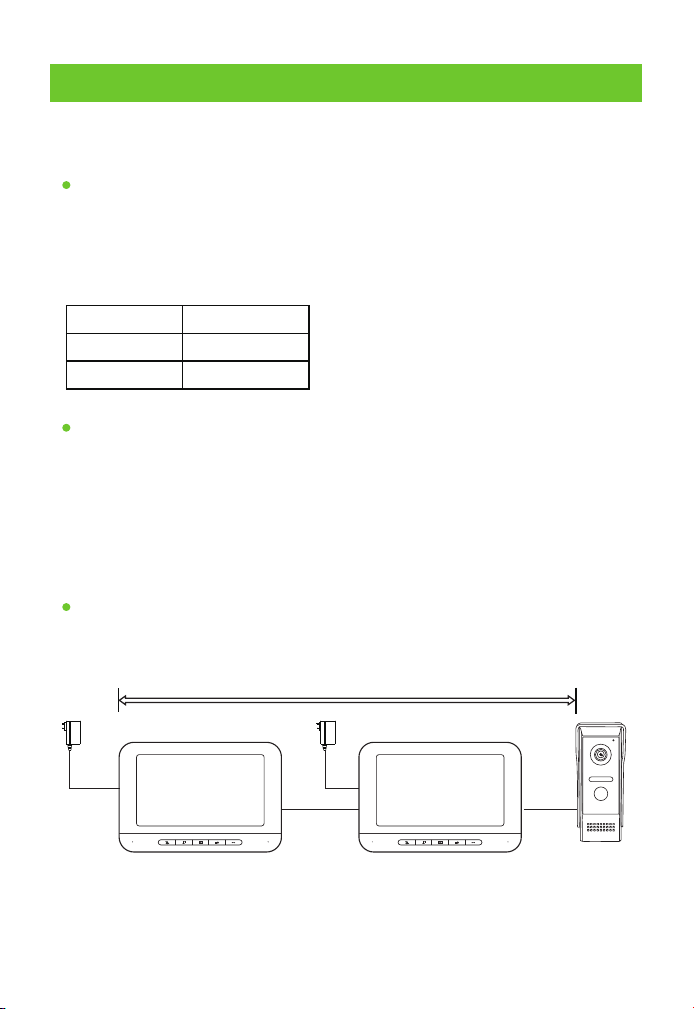
4.1 Wiring Diagram
One Outdoor Unit Connects with One or More Indoor Units
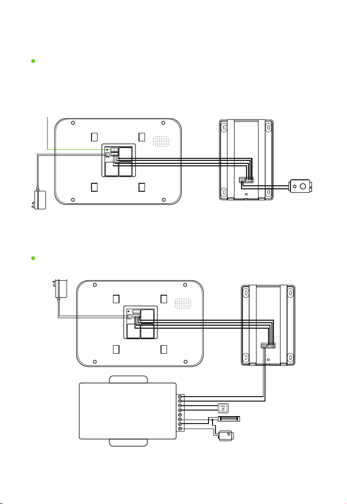
In Combination with Access Control Power Supply Wiring
When it connects with 1-4 indoor units,series connection is made to
connect these screens.
VIDEO--- AUDIO--- GND--- VCC--- CALL---Green Yellow Blue Black Red
+15V--- Lock- --- Lock+---Red Black Red
Outdoor Unit
Electronic
control lock
Connect with
next indoor unit
15V power supply
Indoor Unit
POWER SUPPLY CONTROL
CONTROL+
CONTROL-
PUSH
GND
+12V
+COM
+NC
+NO
Electronic control lock
Electromagnetic lock
Electronic plug lock
Exit button
Outdoor Unit
15V power supply
Indoor Unit
Note: For the operation of access control power supply, please refer to the
operation manual for the access control power supply purchased by yourself.
-13-
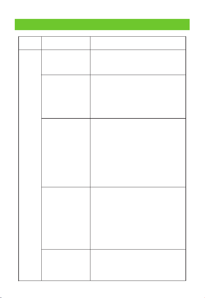
Inspect whether the connection wires of various
colors are properly connected and whether the
indoor unit can hear the sounds from the
outdoor unit.
1. Whether there is ringtone during calling? The
mainboard or microphone of the outdoor unit
needs to be repaired or replaced if no ringtone
or intercom sound can be heard.
2. The indoor unit mainboard needs to be
repaired or replaced if no ringtone or intercom
sound can be heard during calling.
1. Inspect whether a ringback can be heard on
the outdoor unit when calling the indoor unit,
the ringback means that the outdoor unit works
normally.
2. If any talk cannot be heard if a ringback can be
heard on the outdoor unit, it means that the
indoor unit mainboard or microphone has a
failure.
3. If no ringback is heard, it means that the
speaker or mainboard of the outdoor unit has a
failure.
1. First of all, determine the distance from the
speaker’s mouth to the microphone.
2. Inspect whether the turbine is rotated to the
maximum level.
3. Inspect whether the wire diameter exceeds
the specified proportion.
4. Determine whether original power source is
used.
5. Use the test wire to test whether the sound is
normal.
1. Determine whether it is noise due to the
short-distance test of the two units.
2. Whether the original power source is used.
3. Whether the wire for installation is too thin or
too long.
5 Troubleshooting
Failure
Type
Failure
Description
Failure Elimination
Sound
No intercom sound
The intercom
sound is low
Intercom noise
Anyone at the indoor
unit cannot hear what
one says in front of the
outdoor unit
Anyone at the outdoor
unit cannot hear what
one says in front of the
indoor unit
-14-
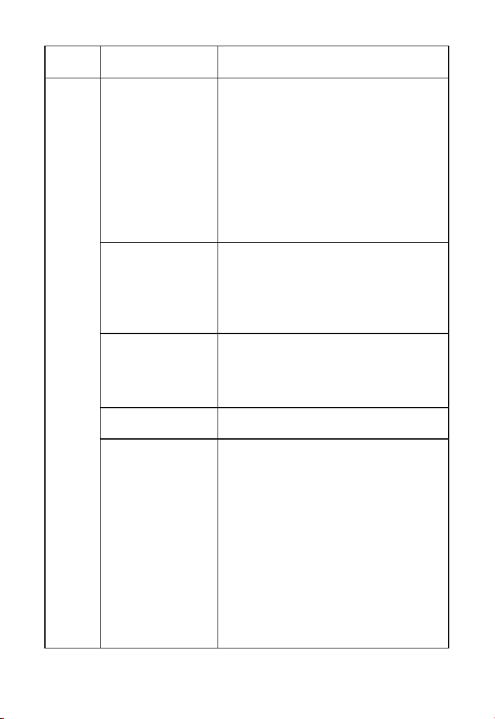
Failure
Type
Failure
Description
Failure Elimination
Video
Black screen
Blue screen
Blurred screen
The display screen is
normally on
The display screen is
normally on with
whitening,blackand
white and too bright
effects
1. Inspect whether the indoor unit intercom
indicator is on. If the intercom indicator is on,
it means that the display screen or driver
board has a failure and the board needs to
be repaired or replaced.
2. In case intercom is not working and the
indicator is off, determine whether the
power source is normal. If the power source
is normal and the black screen remains, it is
determined that the indoor unit mainboard
needs to be repaired or replaced.
1. Inspect whether the wires are correctly
connected.
2. If the blue screen remains after
confirming the wires are correctly
connected, it means that the outdoor
camera needs to be replaced.
1. First of all, determine whether the display
screen is damaged, and it shall be replaced if
it is damaged.
2. If the screen is normal, the driver board
needs to be repaired or replaced.
1. The indoor unit mainboard needs to be
repaired or replaced.
1. If it is whitening, it means that the driver
board needs to be repaired or the screen
and driver board need to be replaced.
2. If it is black & white, adjust the side color
turbine. The driver board needs to be
repaired or replaced if there is no response.
The turbine may have a failure if the colors
are unstable when adjusting the turbine,
and the turbine or mainboard needs to be
replaced.
3. If it is too bright, the side turbine controls
brightness, color and intercom sound
respectively. Any user may choose the most
appropriate position by itself.
-15-
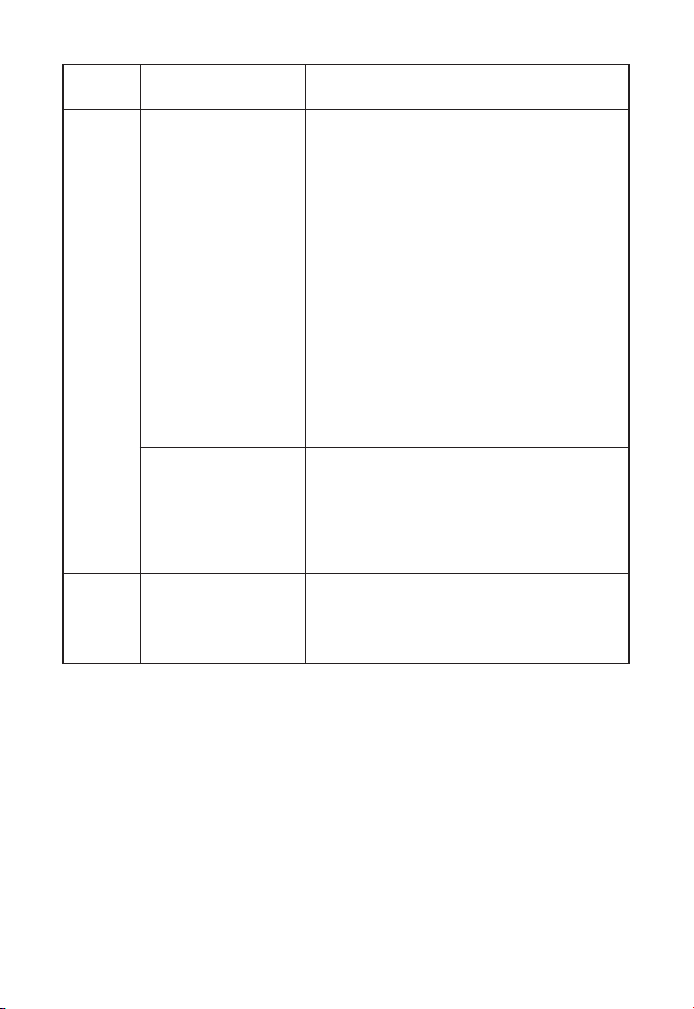
Failure
Type
Failure
Description
Failure Elimination
Call
1. Inspect whether the power source is
normal. Press the monitor button of the
indoor unit to see whether the screen is
normal. The power source is normal if the
screen is normal. If the screen is off, use
another power source to test it. If the screen
is on, the power source has a failure. If the
screen is still off, the indoor unit mainboard
has a failure.
2. If the screen is normal, please inspect
whether the connection is correct.
3. If the screen and wires are normal, short
circuit the blue wire and black wire to see
whether the indoor unit has ringtone. The
outdoor unit has a failure if the blue screen
has ringtone.
1. Inspect whether the mute mode is used.
Reset it to see whether it can resume to
normal state.
2. If no ringtone can be heard after resetting
it, the indoor unit mainboard needs to be
repaired or replaced.
1. Inspect whether the device gets stuck
due to the rapid responses of the keys.
2. Inspect whether many keys are pressed at
the same time.
No response after
calling
Intercom is normal
but no ringtone is
heard
No response after
pressing it
Touch
Key
-16-

6 Instructions
When cleaning the device, power it off first and use soft and dry cloth to
wipe it;
Don't use benzene, diluent or organic solvent such as gasoline to wipe
it,for these may damage the shell or discolor the device and keys;
The device shall be installed at a secure place with good ventilation, dry
air and without direct sunlight, high-intensity magnetic field or dust;
Don't use it with any product not produced by our company;
Don't dismantle it without authorization. Please contact your local
distributor or our technical department in case it has any failure;
Users shall follow the user manual strictly to install and test the
product.Please call our company for technical support if you have any
question;
The door-open button, electronic control lock and access control
power supply are not accessories, and users need to purchase themby
themselves;
The product is updated from time to time, so the manual is for your
reference only. Please be subject to the actual product in case there are
differences.
1.
2.
3.
4.
5.
6.
7.
8.
-17-

ZKTeco Industrial Park, No. 32, Industrial Road,
Tangxia Town, Dongguan, China.
Phone : +86 769 - 82109991
Fax : +86 755 - 89602394
www.zkteco.com
Copyright © 2022 ZKTECO CO., LTD. All Rights Reserved.
