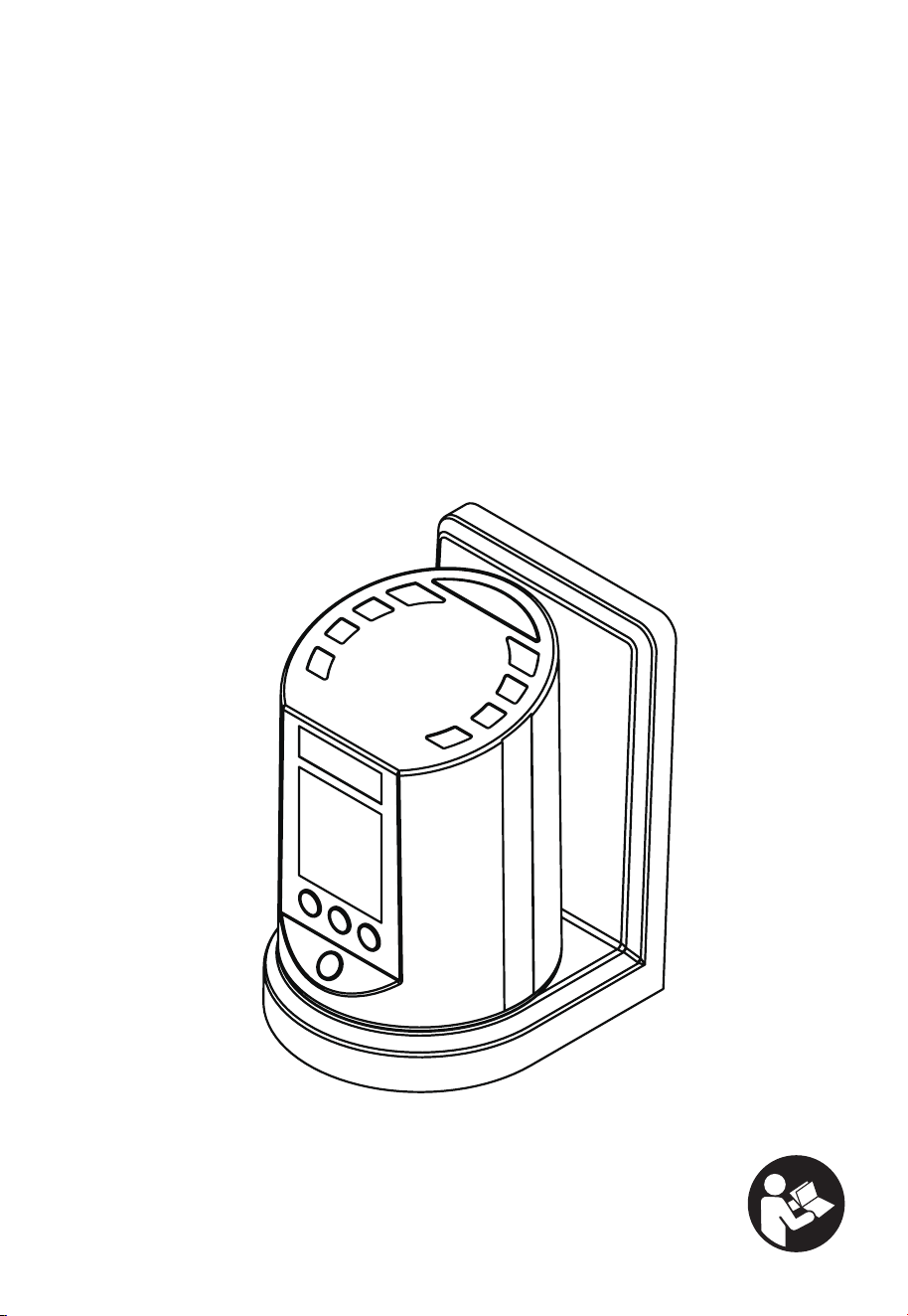
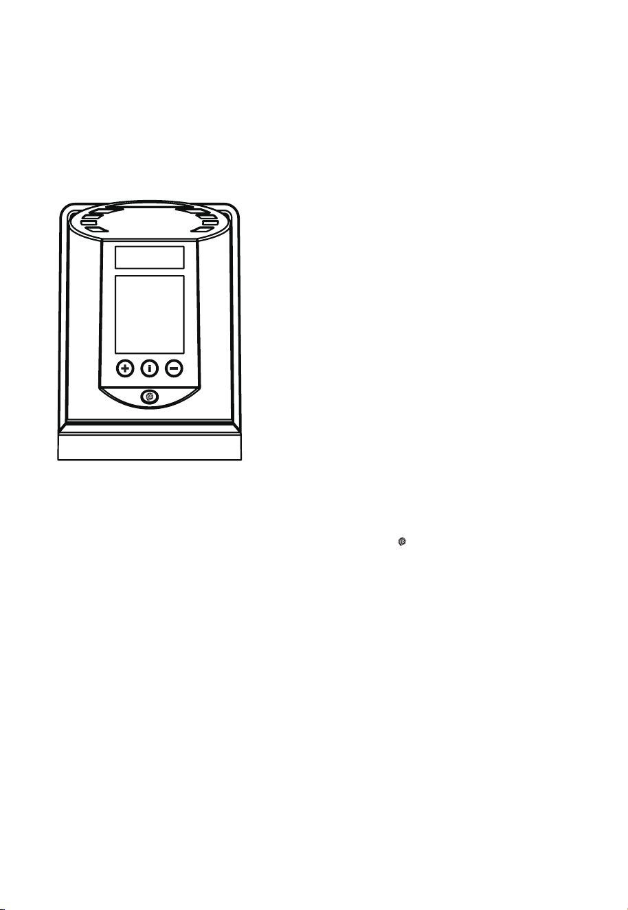
Automatic Tire Inflator
User Manual

2
Chapter I Foreword...................................................................................................................................................... 3
Chapter II Precautions for Use ............................................................................................................................... 4
Chapter III Operation Methods ................................................................................................................................ 4
Chapter IV Technical Parameters .......................................................................................................................... 5
Chapter V Fault Analysis ............................................................................................................................................ 5
Chapter VI Calibration ................................................................................................................................................ 6
Chapter VII Maintenance ........................................................................................................................................... 6
Chapter VIII List of Parts ........................................................................................................................................... 6
Chapter IX Product Warranty .................................................................................................................................. 6
Table of Contents
3
Chapter I Foreword:
Thank you for choosing Automatic Tire Inflator. Please read fully and understand this Manual before installing and using the product
so as to reduce unnecessary faults and damage. If there is anything abnormal during the operation of the machine, please stop using
immediately or contact the dealer or after-sales service timely, who will provide you with prompt and complete service.
1)Press the "+" or "-" button to set the inflation pressure value, and the inflator will automatically inflate the tire after connection.
2)When the set pressure value is reached, the buzzer will beep, and the inflation will stop automatically.
3)Press the " i " button once to convert the display unit: Bar/Psi/Kpa/Kgf
.
4)Press the " i " button twice to start the new tire over-inflation function, and press the " " button after setting until the
inflation starts.

4
Chapter II Precautions for Use:
1 )The center power line must be grounded.
2)The inlet pressure shall not exceed 12.5Bar to avoid damage to the machine.
3)The compressed air must pass through a filter such as an oil-water separator before entering the inflator, so as to prevent corrosion
of the internal components of the inflator.
4)Do not point the air source or the air outlet at any body so as to avoid personal injury.
Chapter III Operation Methods:
3.1Functions of Buttons:
1(
-
): reduces the target pressure value.
2(+): increases the target pressure value.
3( ): Confirmation button.
4( i): function selecting button.
3.2Function Settings:
3.2.1 U nit c onve rsion funct ion:
Press( )once and the current unit flashes. The [SET] icon lights up.
Press(
-
)or(+)to select the unit you wish to use.
Press( )to save(the original unit is Bar, and there are four units available: Bar/Psi/Kpa/Kgf
).
3.2.2 [OPS] function:
1 )Press( )twice, and the [OPS] icon flashes on the screen.
2)Press(
-
)or(+)to select the over-inflation value you wish to achieve and press( )to save.
3)After the over-inflation is set correctly, the [OPS] icon will be displayed on the screen.
4)After clamping the chuck on the inflating valve, press and hold( )until the machine starts to infla
te.
5)When the buzzer beeps, the inflation is completed. Pull off the inflation chuck.
3.2.3 Special Remarks:
1 ) [OPS] is an over-inflation function for the new tire inflated for the first time so as to make the tire fit
tightly with the wheel hub.
2) The over-inflation value is equal to the maximum tire pressure minus the standard tire pressure, e.g., for a new tire with a MAX.
PRESSURE of 350Kpa(51Psi), the maximum tire pressure is 3.5Bar. So if the standard tire pressure is 2.5Bar, the over-inflation shall
be set to 3.5-2.5=1Bar.
*1Bar=100KPa: 1Psi=6.89KPa: 1Bar=1.02Kgf.
i
i
5
Chapter IV Technical Parameters:
Working range 0.5-12 Bar / 7-174 Psi
Accuracy +/-0.08 Bar / +/-1 Psi
Maximum intake pressure 12.5 Bar / 182 Psi
AC power supply AC110~240V(50~60Hz)
Power consumption Max. 10W
Operating temperature -10℃ ~50℃
Humidity ≤95%
Chapter V Fault Analysis:
Fault Possible causes Solutions
There is a leakage after connecting the air
source
The connection is tight enough Check the air channel connection
The inflator is working, but no air inflated The filter or air hose is blocked Clean the filter and check the air hose
After the pressure is set and the inflator is
connected with the tire, the inflator does
not start automatically
The air tube is not connected tightly
Long press the button
At present, the tire pressure is below 0.2Bar
Check the connection to ensure no
air leakage
The inflator deflates very slowly The muffler is blocked Clean the muffler
The LCD displays Er1 The pressure sensor is damaged
Turn off the power and return it to the
factory
The LCD displays Er2 The chuck is leaking air Clamp the chuck to avoid air leakage
The LCD displays Er3
The tire pressure to be inflated is too high,
greater than 13 Bar
Stop inflation
The LCD displays Er4
The inlet and outlet ends are connecte
d
incorrectly
Connect the two ends correctly according
to the inlet and outlet end indication signs
The LCD displays Er5 Low voltage Check the power supply
The LCD displays Er6 The program calibration data is lost Return it to the factory
The LCD displays Er7 The program calibration data is lost Return it to the factory
The LCD displays Er8
The intake air supply pressure is lower than
the set pressure value of the pneumatic tire
or there is no intake pressure
Check the air supply

6
Chapter VI Calibration:
This equipment has been calibrated in the factory and has the self-calibration function. If calibration is required, please contact the
manufacturer.
Chapter VII Maintenance:
The inflator has precision electronic components such as built-in integrated circuits and pressure sensors. To ensure that it can work
normally and safely, rough operation shall be avoided in daily use, and daily maintenance is also essential.
1)Check the connected air channel regularly for leakage, and repair in time if any.
2)Check whether the oil-water separator is working normally regularly, and drain the water in the oil-water separator in time to
prevent the oil in the air channel from entering the inflator, which may damage the inflator or reduce the service life.
3)Check the power supply connected to the inflator regularly for potential safety hazards in the circuit.
4)Keep the inflator clean and tidy. Often wipe the machine body with a clean soft c
loth. Do not splash water or oil on the inflator body,
so as to prevent damage to the inflator or other safety accidents.
Chapter VIII List of Parts:
1 Main machine 1
2 Wall mounting board 1
3 7.6m air hose 1
4 Power cord 1 (connected to the main machine)
5 Instruction 1
6 Hook 1
7 Board screw 4 (M4.8*38 screw)
Chapter IX Product Warranty:
1)The whole machine is covered under one year free warranty, starting from the date of purchase by the user, and
the product will enjoy free maintenance throughout the service life.
2)The following conditions are not covered under the free warranty:
Damage caused by installation, use and maintenance incompliant with the product's Operation Instruction; usage under abnormal conditions
or man-made d
amage; the warranty period is expired.
Note: The above daily maintenance shall be carried by professional technicians or trained personnel. In case of a failure, please contact
our after-sales service staff or dealers immediately to enjoy professional services. Do not disassemble the inflator by yourself so as to
avoid unpredictable condition.
8 Hook screw 1 (M6*38 screw)

No.
Date
Model: W110
Version No: V1.0-2303