Loading ...
Loading ...
Loading ...
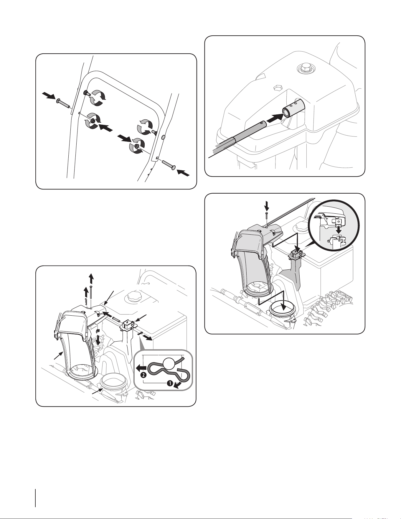
Figure 3-6
Figure 3-7
4. Squeeze the trigger on the joystick and rotate the chute
by hand to face forward. The holes in the chute rotation
assembly will be facing up. See Fig. 3-8.
NOTE: The chute will not rotate without squeezing the
trigger on the joystick.
5. Rotate the joystick to 1 o’clock position so the arrow on the
pinion gear faces upward See Fig. 3-9).
NOTE: The joystick will be angled slightly to the right at the
one o’clock position. See “Top View” in Fig. 3-8.
NOTE: The pinion gear is located on the front of the unit
below the control panel.
• Reattach the two carriage screws and lock nuts removed
earlier as shown in Figure 3-4.
Figure 3-4
• Finish securing the handle by tightening the top two lock
nuts loosened earlier. Remove and discard any rubber
bands, if present. They are for packaging purposes only.
Chute Assembly
1. Remove wing nut and hex screw from chute control
assembly and clevis pin and cotter pin from chute support
bracket. See Fig. 3-5.
Chute Control Assembly
Chute
Chute Support
Bracket
Chute Base
Figure 3-5
2. Insert round end of the chute control rod (hole pointing
upward) as far as possible into chute control assembly. See
Fig. 3-6.
3. Place chute onto chute base with the chute control rod
positioned under the handle panel. Reinstall the hex bolt
previously removed but do not secure with wing nut at this
time. See Fig. 3-7.
8 Section 3— ASSembly & Set-Up
Loading ...
Loading ...
Loading ...