Loading ...
Loading ...
Loading ...
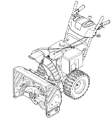
Lamp Wiring Harness (If equipped)
The post on the cable tie attaching the lamp wiring harness to
the lower handle should be plugged into the hole in the lower
handle. Pull the slack portion of the wiring harness through the
cable tie to prevent interference with the recoil starter handle.
See Fig. 3-16.
Figure 3-16
Tires
Pneumatic (Air-Pressurized) Tires
The tires are over-inflated for shipping purposes. Check the tire
pressure before operating the snow thrower. Refer to the tire side
wall for tire manufacturer’s recommended psi and deflate (or
inflate) the tires as necessary.
WARNING: Under any circumstance do not exceed
manufacturer’s recommended psi. Equal tire
pressure should be maintained at all times. Excessive
pressure when seating beads may cause tire/rim
assembly to burst with force sufficient to cause
serious injury. Refer to sidewall of tire for
recommended pressure.
NOTE: Equal tire pressure is to be maintained at all times for
performance purposes.
Non-Pneumatic (Airless) Tires
Some units are equipped with non-pneumatic tires. Therefore,
these airless tires are considered maintenance free with regards
to air pressure.
Adjustments
Skid Shoes
The snow thrower skid shoes are adjusted at the factory for
shipping purposes. Adjust them downward, if desired, prior to
operating the snow thrower.
CAUTION: It is not recommended that you operate this snow
thrower on gravel as it can easily pick up and throw loose gravel,
causing personal injury or damage to the snow thrower and
surrounding property.
• For close snow removal on a smooth surface, raise skid
shoes higher on the auger housing.
• Use a middle or lower position when the area to be cleared
is uneven, such as a gravel driveway.
NOTE: If you choose to operate the snow thrower on a gravel
surface, keep the skid shoes in position for maximum clearance
between the ground and the shave plate.
NOTE: Some models are equipped with reversible skid shoes
and may be turned over to increase their lifespan.
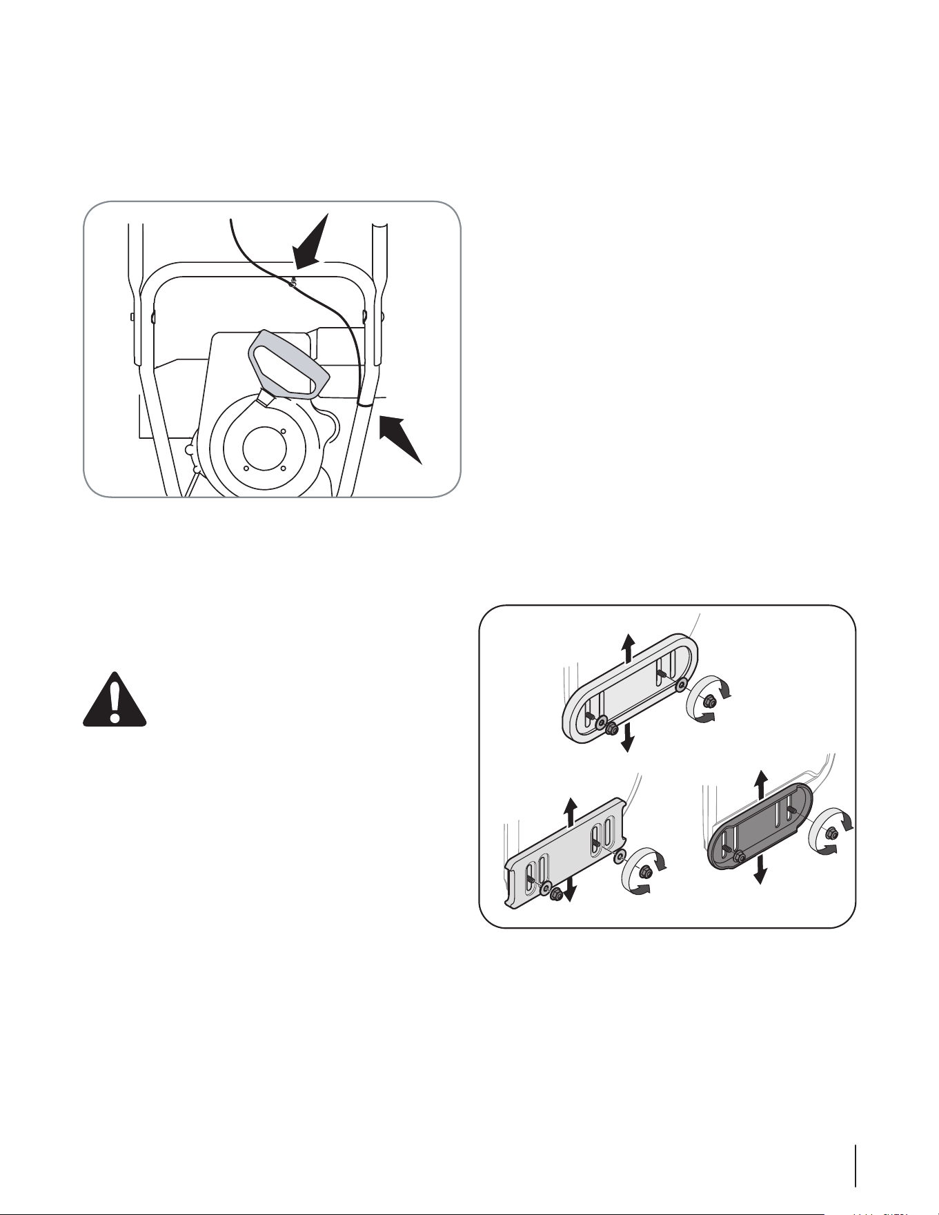
To adjust the skid shoes:
1. Loosen the four hex nuts (two on each side), washers (if
equipped) and carriage bolts. Move skid shoes to desired
position. See Fig. 3-17.
2. Make certain the entire bottom surface of skid shoe is
against the ground to avoid uneven wear on the skid
shoes.
3. Retighten nuts, washers (if quipped) and bolts securely.
Figure 3-17
11Section 3 — ASSembly & Set-Up
Loading ...
Loading ...
Loading ...