ITEM # 5228467
MODEL # 149148 / 28WM373-TPF11
Español p. 32
Serial Number:
SS23021
Purchase Date:
Questions, problems, missing parts? Before returning to your retailer,
call our customer service department at 866-439-9800, 8 a.m. - 8 p.m.,
EST, Monday - Sunday. You can also contact us at [email protected].
ALLEN+ROTH and logo design are trademarks or
registered trademarks of LF, LLC.
All rights reserved.
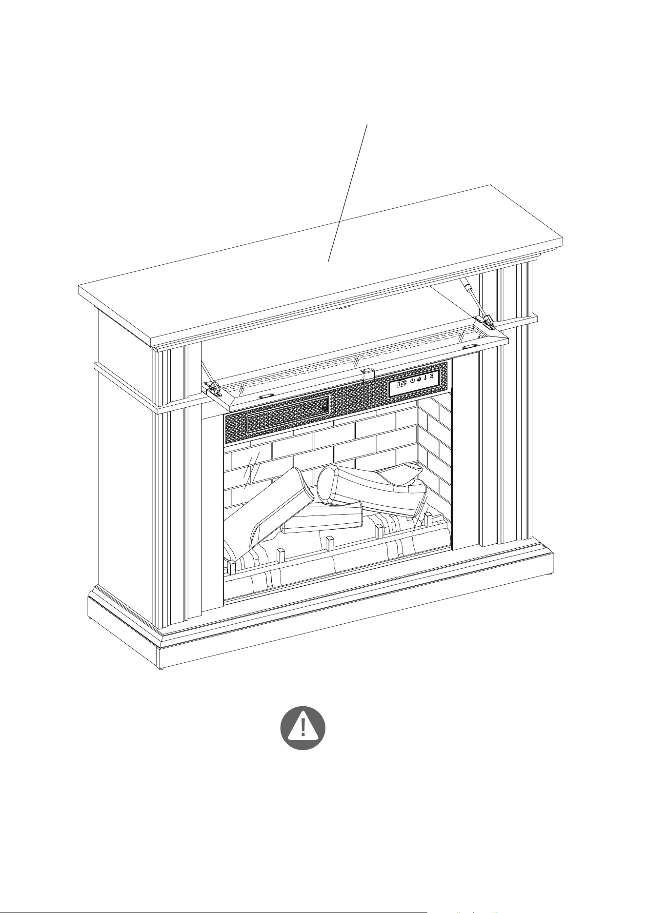
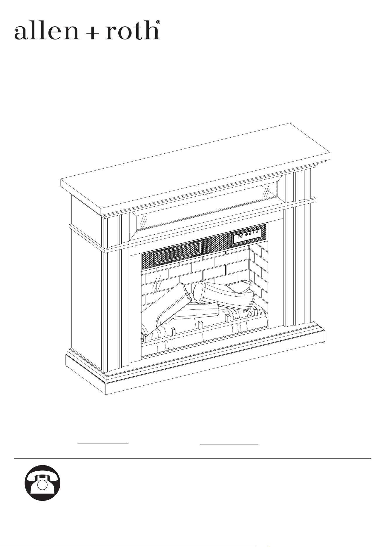
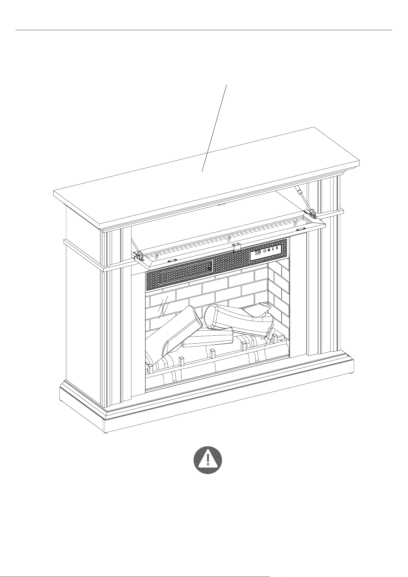
51 in
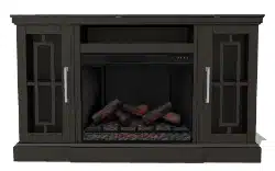
ELECTRIC FIREPLACE

2
28WM373 REV2.0
PRODUCT SPECIFICATIONS
TABLE OF CONTENTS
VOLTAGE 120VAC, 60 Hz
AMPS 12.5 Amps
WATTS 1500 Watts
Product Specications .............................................................................................................................2
Safety Information.....................................................................................................................................3
Maximum Load........................................................................................................................................
..5
Package Contents.....................................................................................................................................6
Hardware Contents...................................................................................................................................8
Preparation..............................................................................................................................................
..9
Assembly Instructions...............................................................................................................................9
Operating Instructions.............................................................................................................................24
Troubleshooting.....................................................................................................................................
..26
FCC/IC Information.................................................................................................................................27
Care and Maintenance............................................................................................................................27
Warranty................................................................................................................................................
..28
Battery Replacement..............................................................................................................................29
Replacement Parts List.........................................................................................................................
..30
3
28WM373 REV2.0
SAFETY INFORMATION
When using electrical appliances, basic precautions should always be followed to reduce the risk
of re, electrical shock, and injury to persons including the following:
1. Read all instructions before using this appliance.
2. DANGER – High temperatures may be generated under certain abnormal conditions. Do not
partially or fully cover or obstruct the front of this heater.
3. CAUTION: Never leave the heater operating unattended. Extreme caution is necessary if
unsupervised children or
people of reduced physical or mental capabilities
are nearby.
4.
The appliance is not to be used by children or persons with reduced physical, sensory or mental
capabilities, or lack of experience and knowledge, unless they have been given supervision or
instruction.
5.
Always unplug this appliance when not in use.
6. Do not operate any heater with a damaged cord or plug or after the heater malfunctions, has
been dropped or damaged in any manner. Discard heater, or return to authorized service facility
for examination and/or repair.
7. Do not use outdoors.
8. This heater is not intended for use in bathrooms, laundry areas and similar indoor locations.
Never locate this appliance where it may fall into a bathtub or other water container.
9. Do not run cord under carpeting. Do not cover cord with throw rugs, runners
or the like. Arrange cord away from trac areas and where it will not be
tripped over.
10. To disconnect heater, turn controls to o, and turn o power to heater circuit at main disconnect
panel (or operate internal disconnect switch if provided).
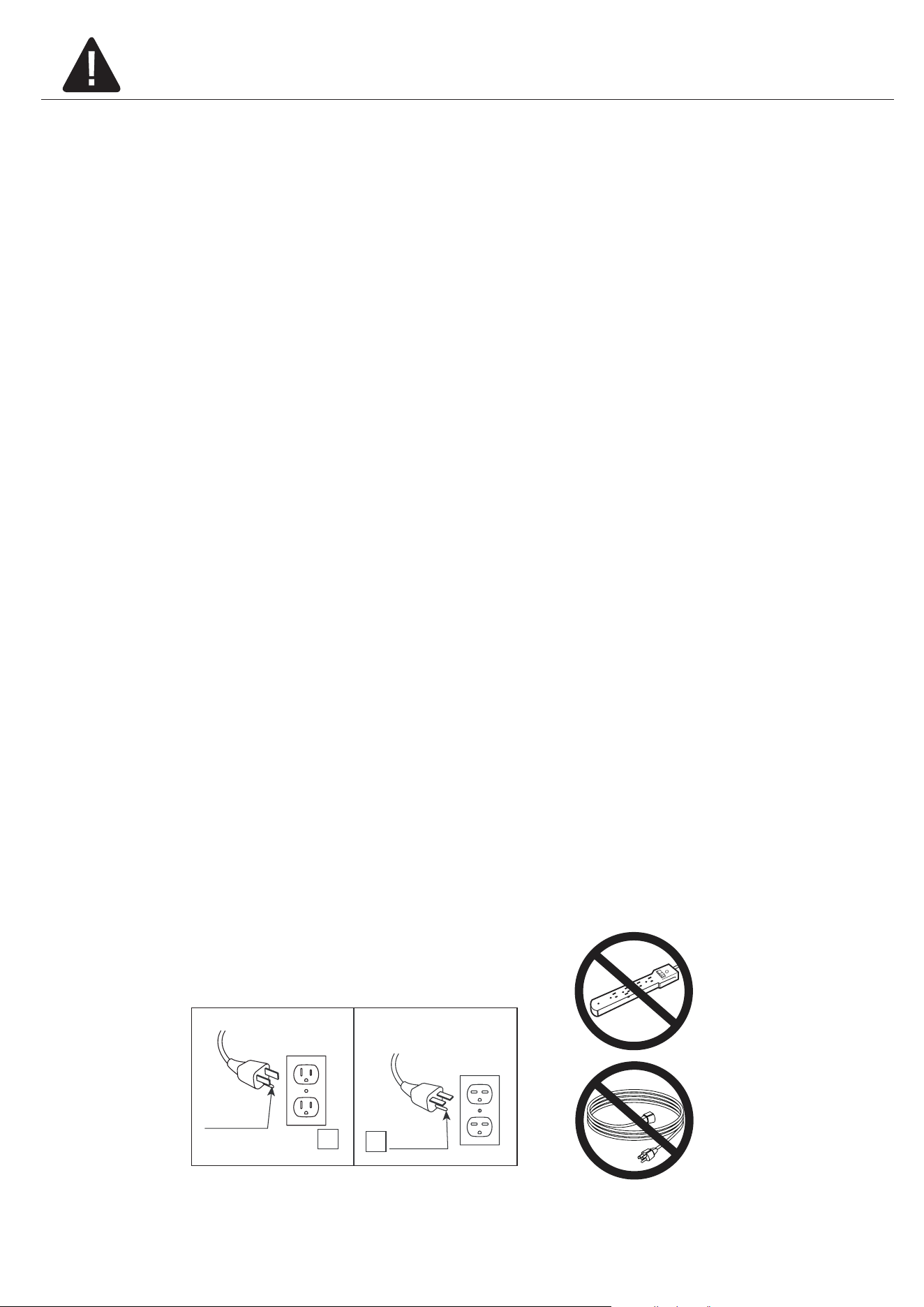
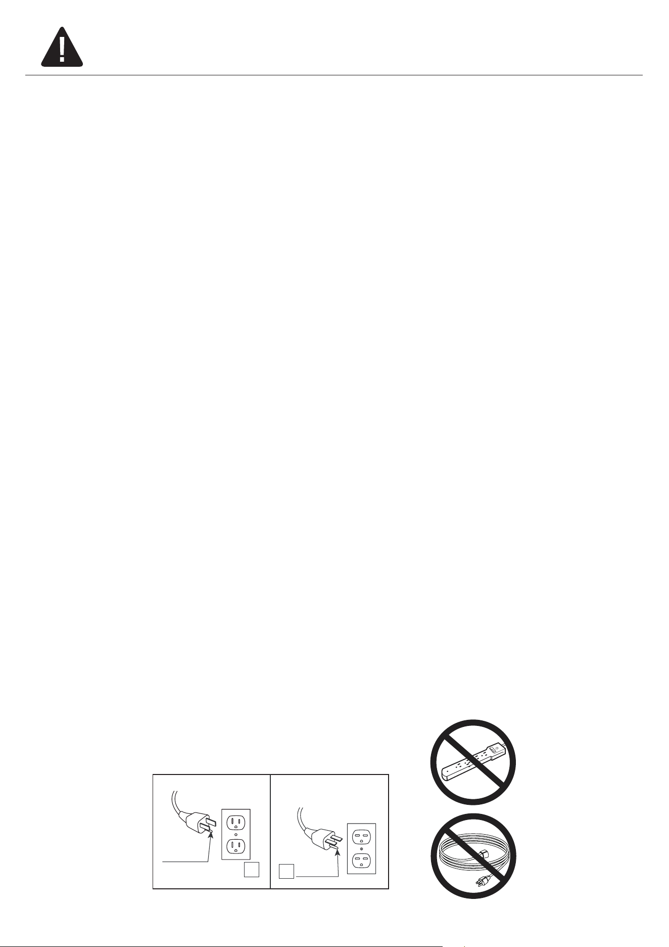
11. Connect to properly grounded outlets only. This heater is for use on 120 volts. The cord has a
plug as shown at A in Fig.1 Do not use a 2 prong adapter. Never use with an extension cord or
relocatable power tap (outlet/power strip).
A
B
Fig.1

4
28WM373 REV2.0
12. Do not insert or allow foreign objects to enter any ventilation or exhaust opening as this may
cause an electric shock or re, or damage the appliance.
13. To prevent a possible re, do not block air intakes or exhaust in any manner. Do not use on soft
surfaces, like a bed, where opening may become blocked.
14. This appliance has hot and arcing or sparking parts inside. Do not use it in areas where gasoline,
paint or ammable liquids are used or stored. This replace should not be used as a drying rack
for clothing. Christmas stockings or decorations should not be hung in the area of it.
15. Use this appliance only as described in the manual. Any other use not recommended by the
manufacturer may cause re, electric shock or injury to persons.
16. This heater may include a visual alarm to warn that parts of the heater are getting excessively
hot. If the alarm ashes immediately turn the heater o and inspect for any objects on or adjacent
to the heater that may cause high temperatures.
DO NOT OPERATE THE HEATER WITH THE ALARM FLASHING!
SAVE THESE INSTRUCTIONS
5
28WM373 REV2.0
MAXIMUM LOAD
18.14 kg / 40 lb
WARNING
Loads heavier than the maximum weights specied may result in instability, causing tip
over resulting in death or serious injury.
MAXIMUM LOAD
6
28WM373 REV2.0
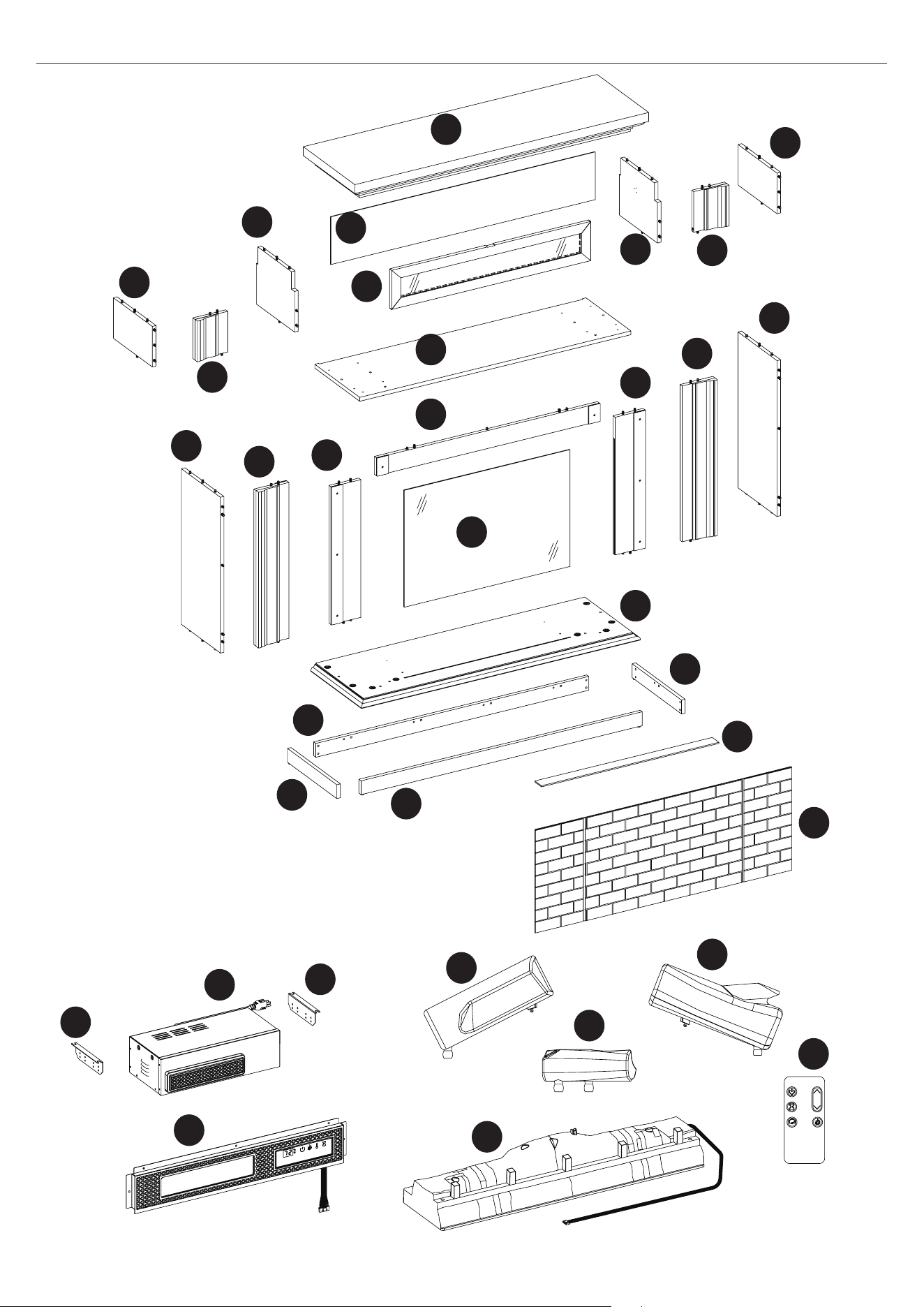
PACKAGE CONTENTS
O
N
R
I
J
X
Y
S
T
U
G
F
P
Q
B
C
E
D
M
H
A
V
W
K
L
EI
EJ
EK
EL
EH
EA
EF
EF
EB

7
28WM373 REV2.0
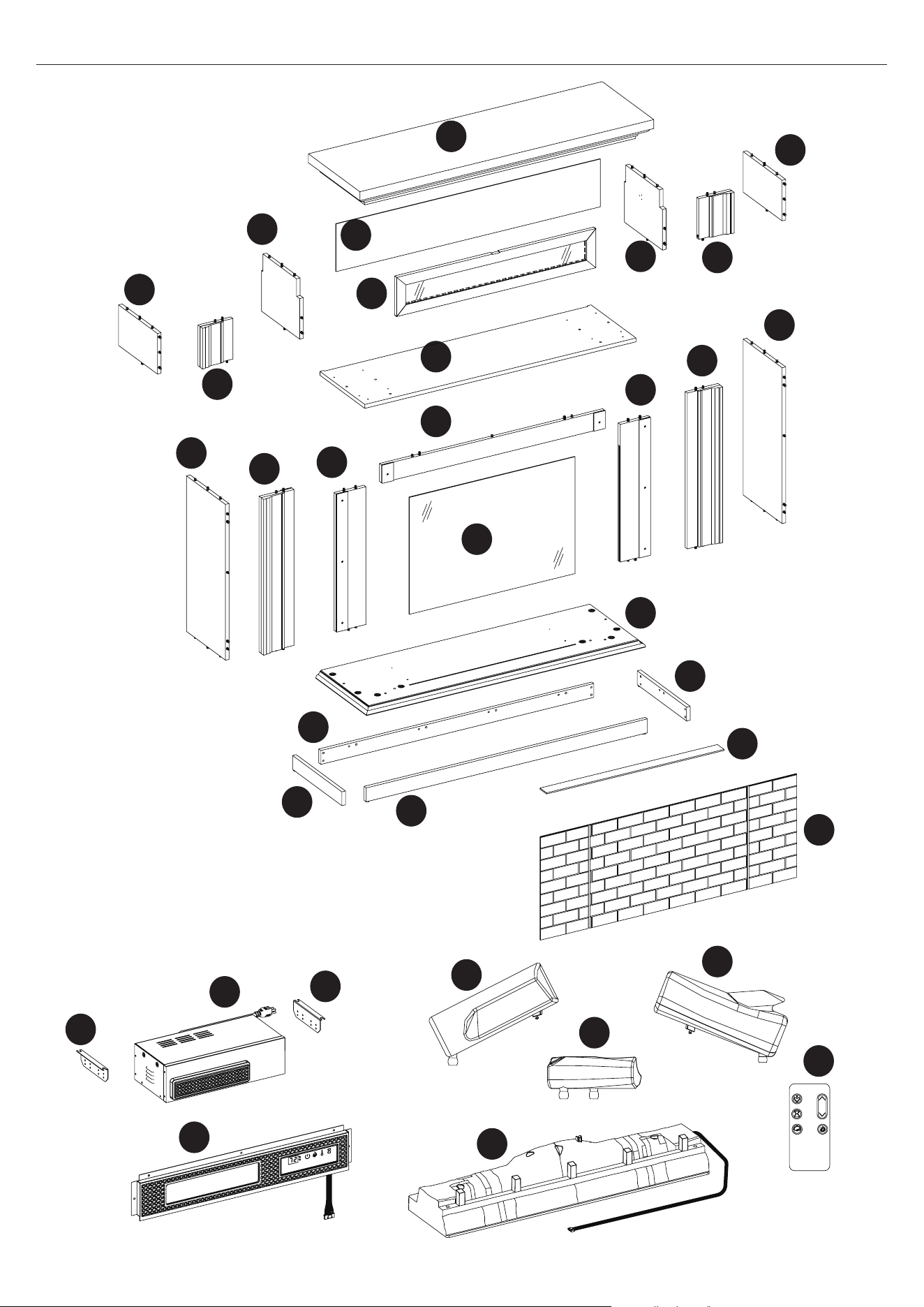
PACKAGE CONTENTS
PART DESCRIPTION QUANTITY
A Bottom Panel 1
B Base Left Panel 1
C Base Back Panel 1
D Base Right Panel 1
E Base Front Panel 1
F Left Upper Front Panel 1
G Top Panel 1
H Left Upper Side Panel 1
I Left Upper Partition 1
J Right Upper Front Panel 1
K Right Upper Side Panel 1
L Right Upper Partition 1
M Flip Down Door 1
N Fixed Shelf 1
O Upper Back Panel 1
P Left Lower Front Panel 1
Q Left Side Panel 1
R Right Lower Front Panel 1
S Right Side Panel 1
T Left Surround Panel 1
U Upper Surround Panel 1
V Right Surround Panel 1
W Glass Panel 1
X Electric Fireplace Back Panel 1
Y Back Panel Frame 1
EA Front Panel with Control Button 1
EB Heater Box 1
EF Bracket 2
EI Ember Bed 1
EJ Log Set Left 1
EK Log Set Right 1
EL Log set Middle 1
EH Remote 1
8
28WM373 REV2.0
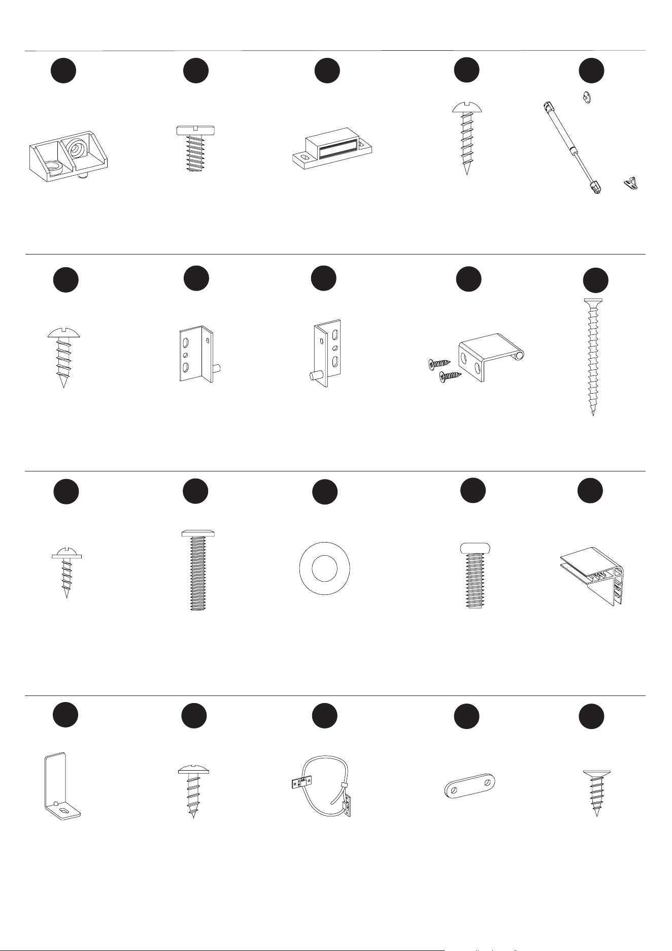
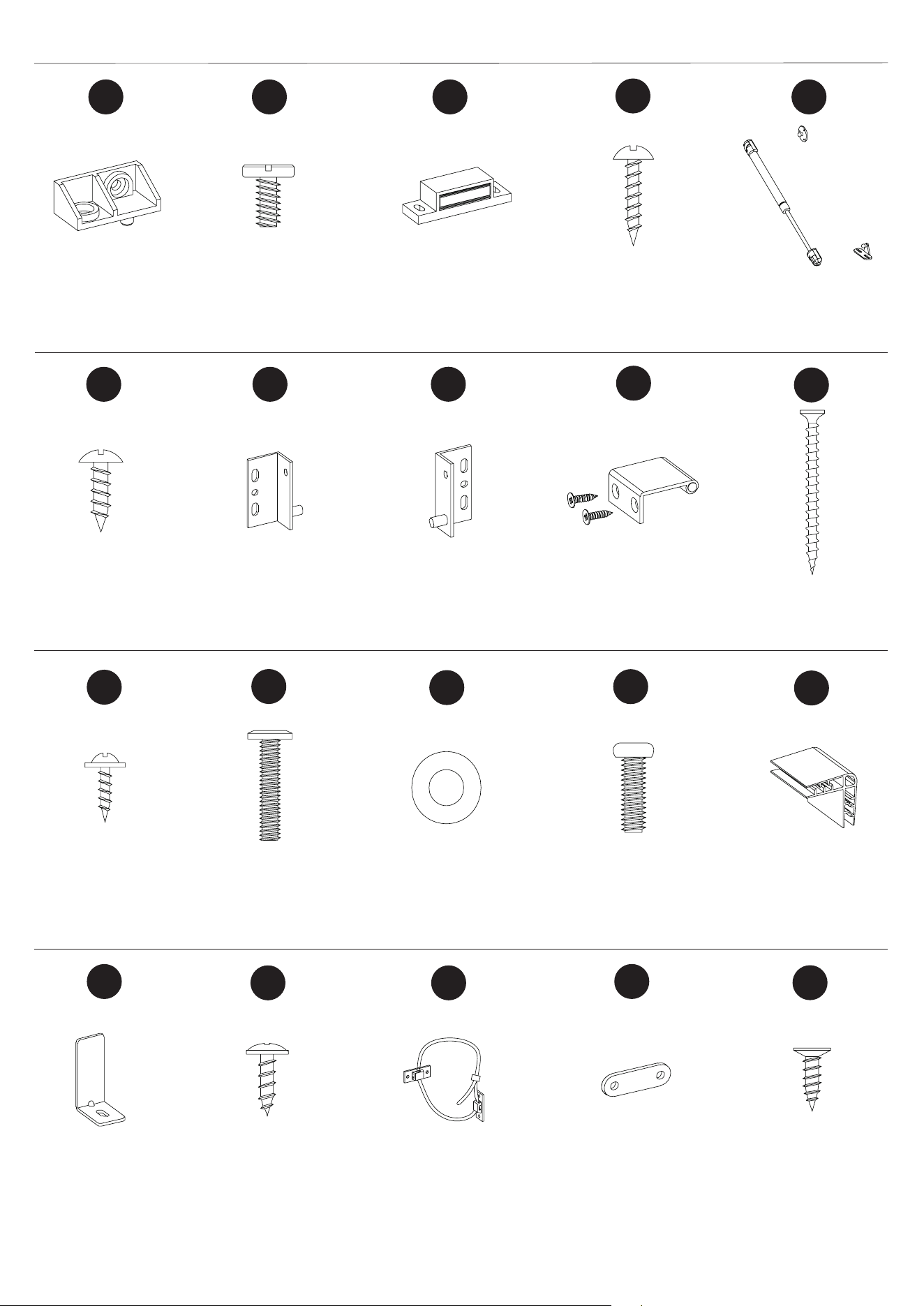
HARDWARE CONTENTS
Ø4x15mm
Screw
Ø3.5x12mm
Screw
Right Pin Hinge
Left Pin Hinge
Handle (with screw)
Qty: 14
Qty: 1
Qty: 2
Qty: 32
Qty: 8
Qty: 1
Qty: 2
Qty: 10
Qty: 4
Qty: 16
Qty: 1
Qty: 6
Qty: 2
Qty: 2
Qty: 21
Qty: 1
Qty: 8
AA
KK
BB
GG
CC
HH
DD
II
EE
FF
JJ
Ø4x12mm
Bolt
Metal Bracket
Tipping Restraint
Hardware
LL
MM
OO
QQ RR
TT
SS
Qty: 2
Qty: 4
Ø6.3x12mm
Bolt
Ø6.3x30mm
Bolt
Ø16mm
Washer
Clip
Plastic Connector
Block
Magnetic Catch
Ø3x15mm
Screw
Gas Spring
Ø3x12mm
Screw
Metal Plate
Ø3x12mm
Screw
Ø4x50mm
Screw
Qty: 2
NN
PP
9
28WM373 REV2.0
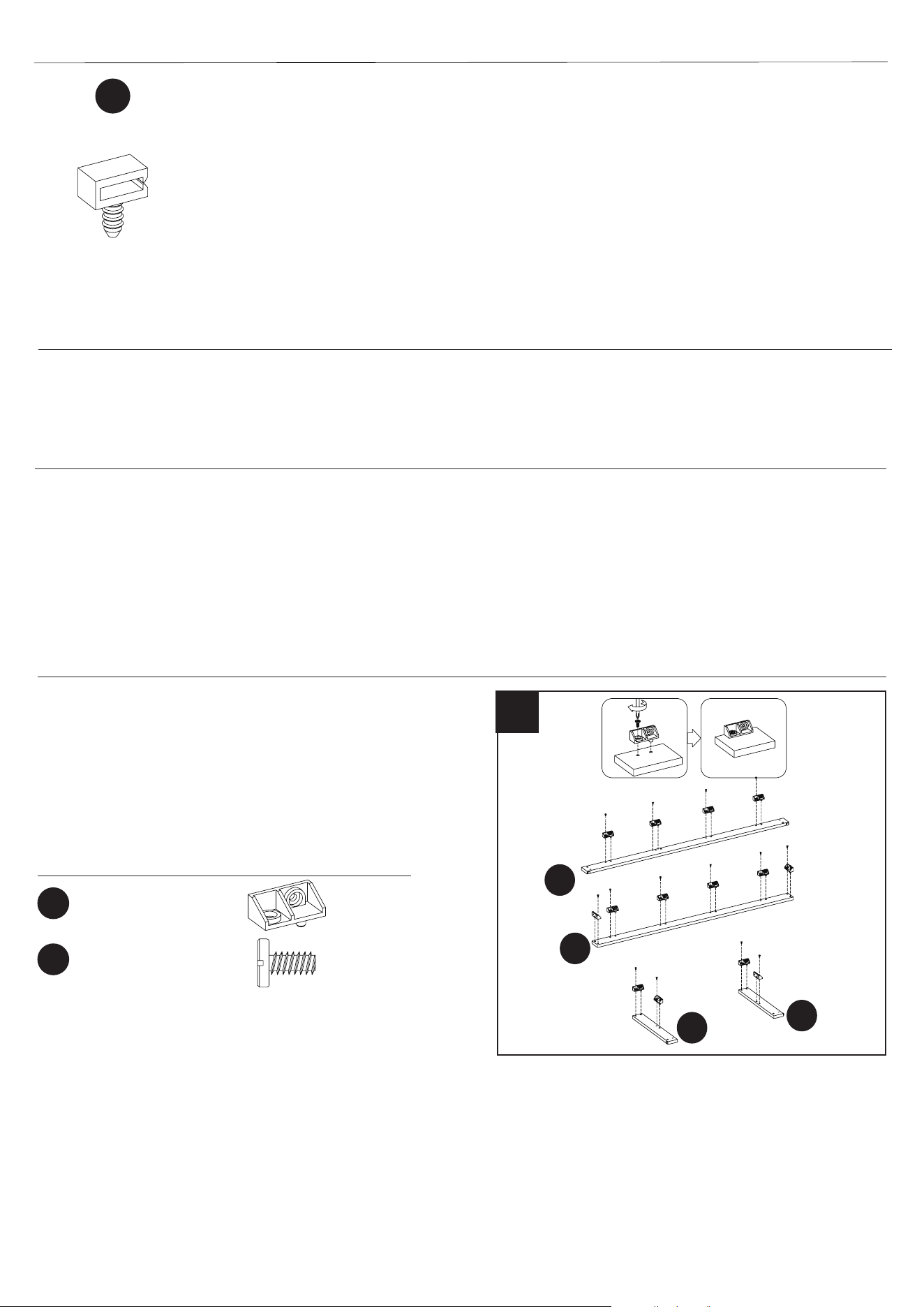
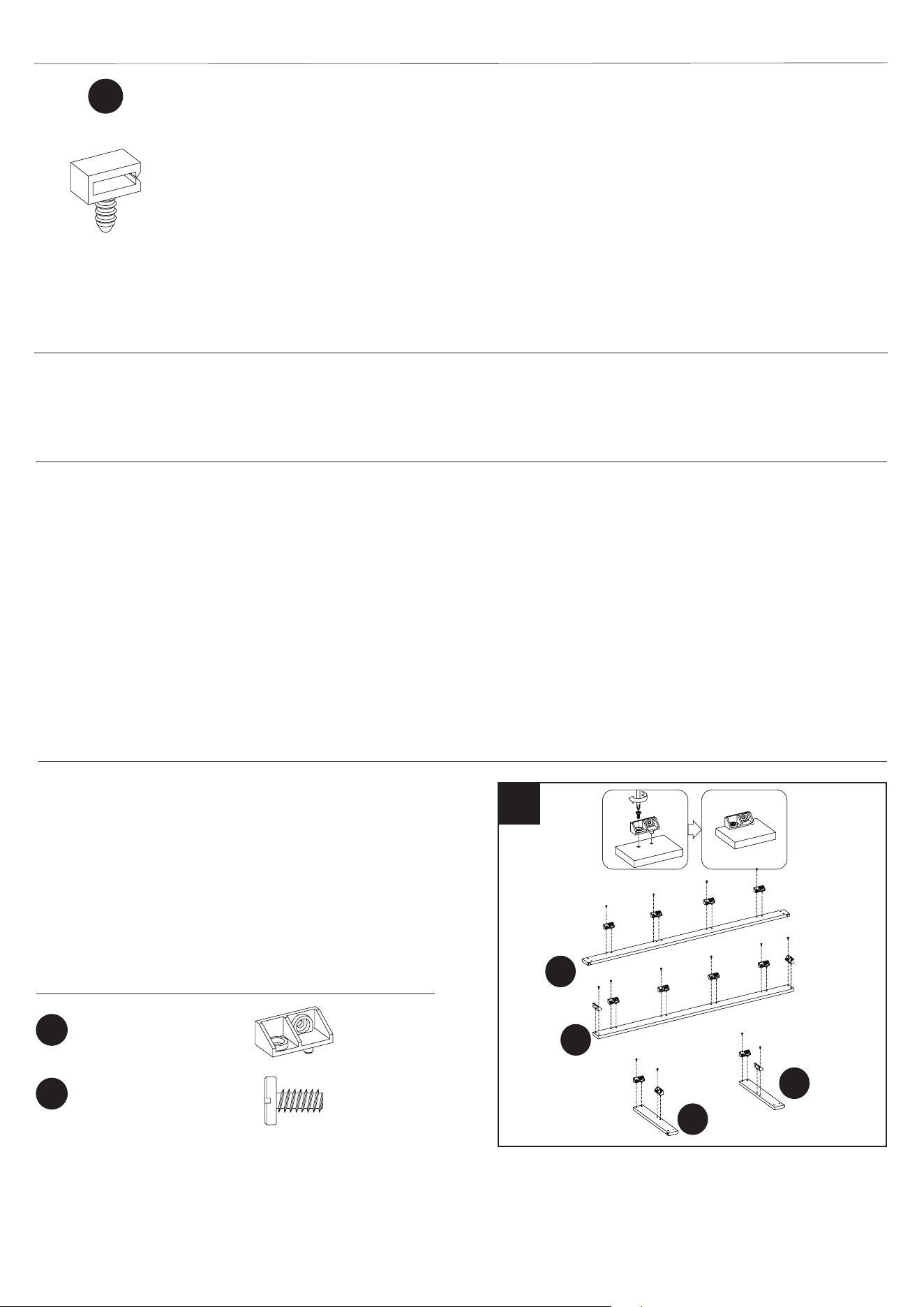
HARDWARE CONTENTS
Qty: 3
UU
Wire Clip
Ø6.3x12mm
Bolt
Plastic Connector
Block
ASSEMBLY INSTRUCTIONS
PREPARATION
Before beginning assembly of product, make sure all parts are present. Compare parts with package
contents list and hardware contents list. If any part is missing or damaged, do not attempt to
assemble, install or operate the product. To protect the product from possible scratches, please
assemble the parts on a scratch-free surface.
Estimated Assembly Time: 45-60 minutes
Tools Required for Assembly (not included): Phillips screwdriver, scissors and utility knife.
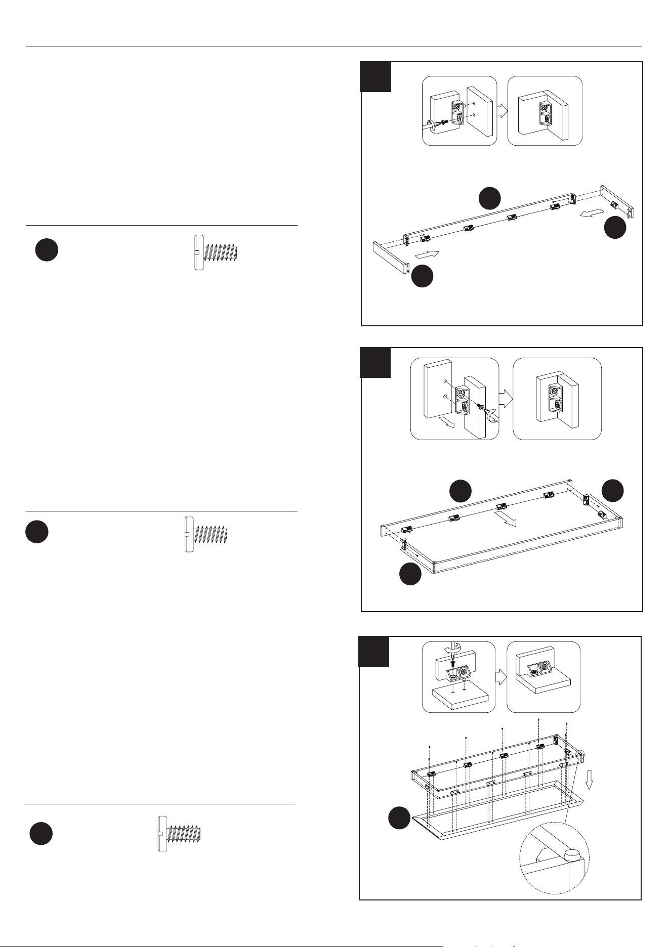
1
AA
BB
Hardware Used
x 14
x 14
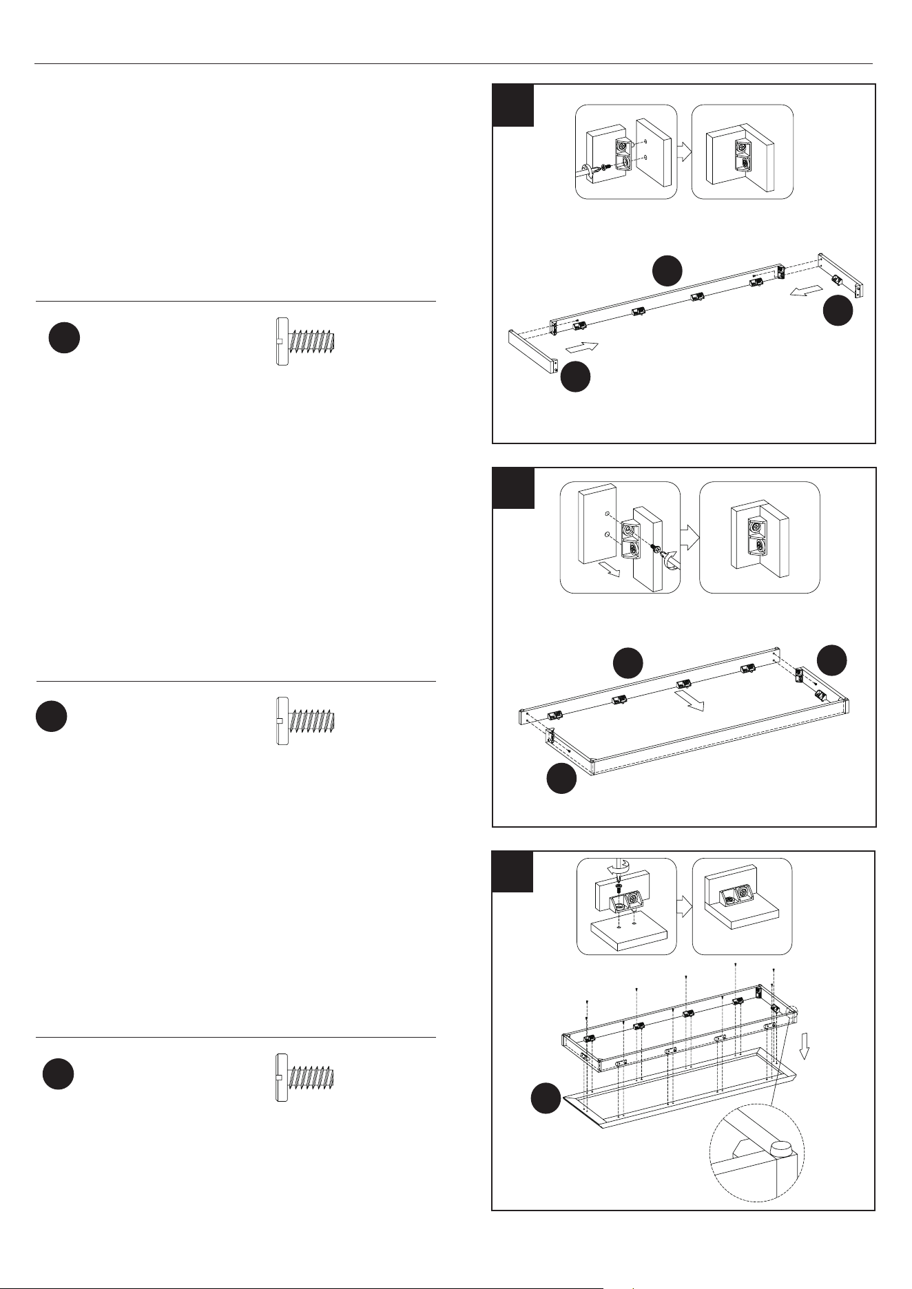
1. Preparing the Base Panels
• Attach the Plastic Connector Blocks (AA) to the
Base Front Panel (E) with Bolts (BB).
• Repeat for Base Back Panel (C), Base Left
Panel (B), and Base Right Panel (D).
C
E
B
D
10
28WM373 REV2.0
Ø6.3x12mm
Bolt
2
BB
Hardware Used
x 2
2. Connecting the Bottom Rails
• Attach Base Left Panel (B) and Base Right Panel
(D) to the Base Back Panel (C) by inserting the
Bolts (BB) through the Plastic Connector Blocks
(AA).
• Tighten with a Phillips screwdriver as shown.
B
D
C
4
Hardware Used
4. Attaching the Bottom Panel to the Bottom
Rails Assembly
• Insert the Bolts (BB) through the holes in the
Plastic Connector Blocks (AA) to attach the
Bottom Panel (A) to the Bottom Rails Assem-
bly.
A
E
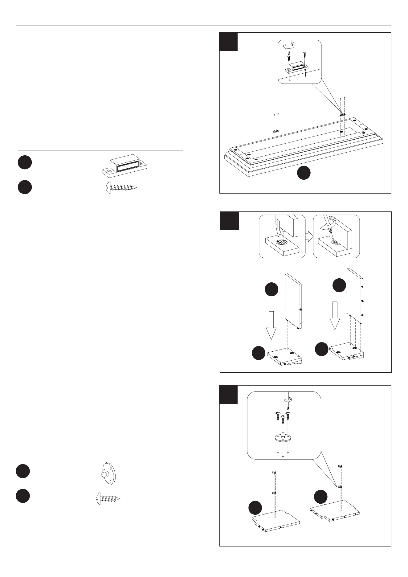
3
Hardware Used
3. Connecting the Bottom Rails
• Attach the Base Front Panel (E) to the Base Left
Panel (B) and Base Right Panel (D) by
inserting the Bolts (BB) through the Plastic
Connector Blocks (AA).
• Tighten with a Phillips screwdriver as shown.
Ø6.3x12mm
Bolt
Ø6.3x12mm
Bolt
BB
BB
x 2
x 10
D
B
ASSEMBLY INSTRUCTIONS
11
28WM373 REV2.0
ASSEMBLY INSTRUCTIONS
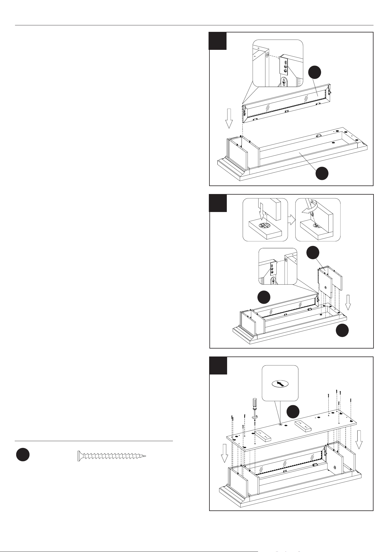
5
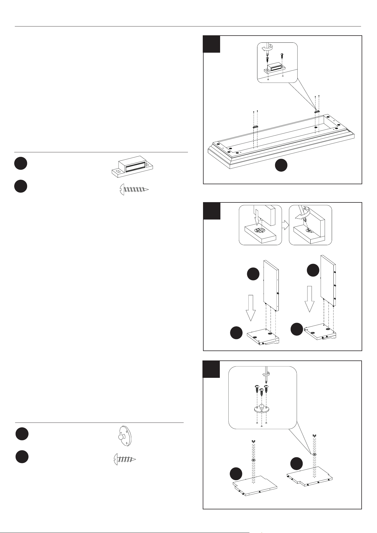
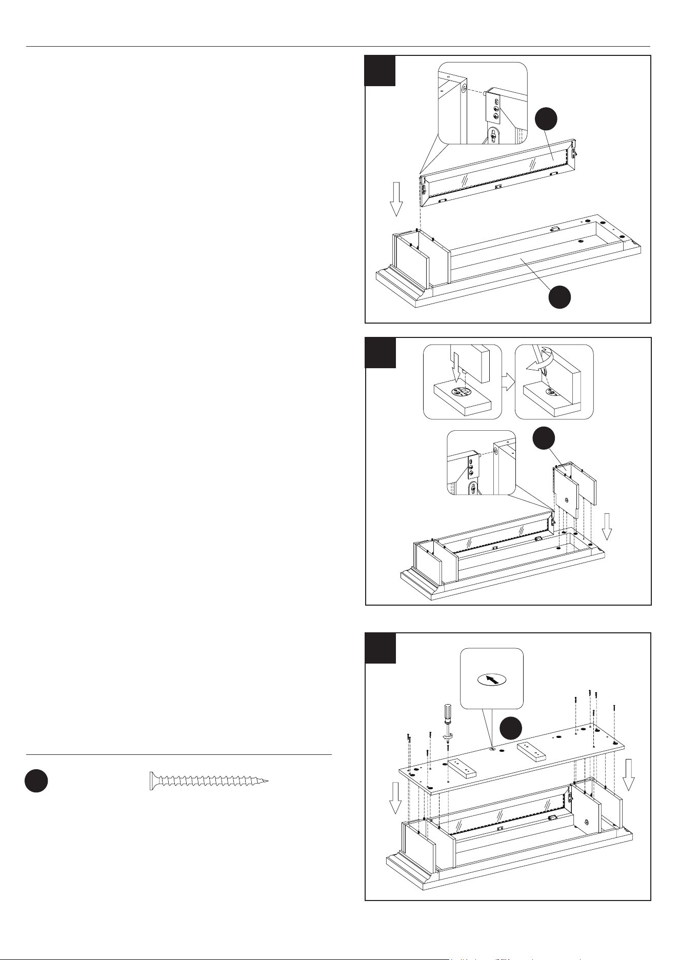
5. Attaching the Door Catch
• Locate the Top Panel (G) and place on a at
surface.
• Attach the Magnetic Door Catches (CC) to the Top
Panel (G) using Screws (DD) where indicated by
the diagram.
Note: Do not tighten the screws in this step. After
assembling the door in step 29, adjust the
magnets position forward or backward to
better match the door to the unit, and then
tighten the screws.
G
CC
DD
Hardware Used
x 2
x 4
Magnetic Catch
Ø3x15mm
Screw
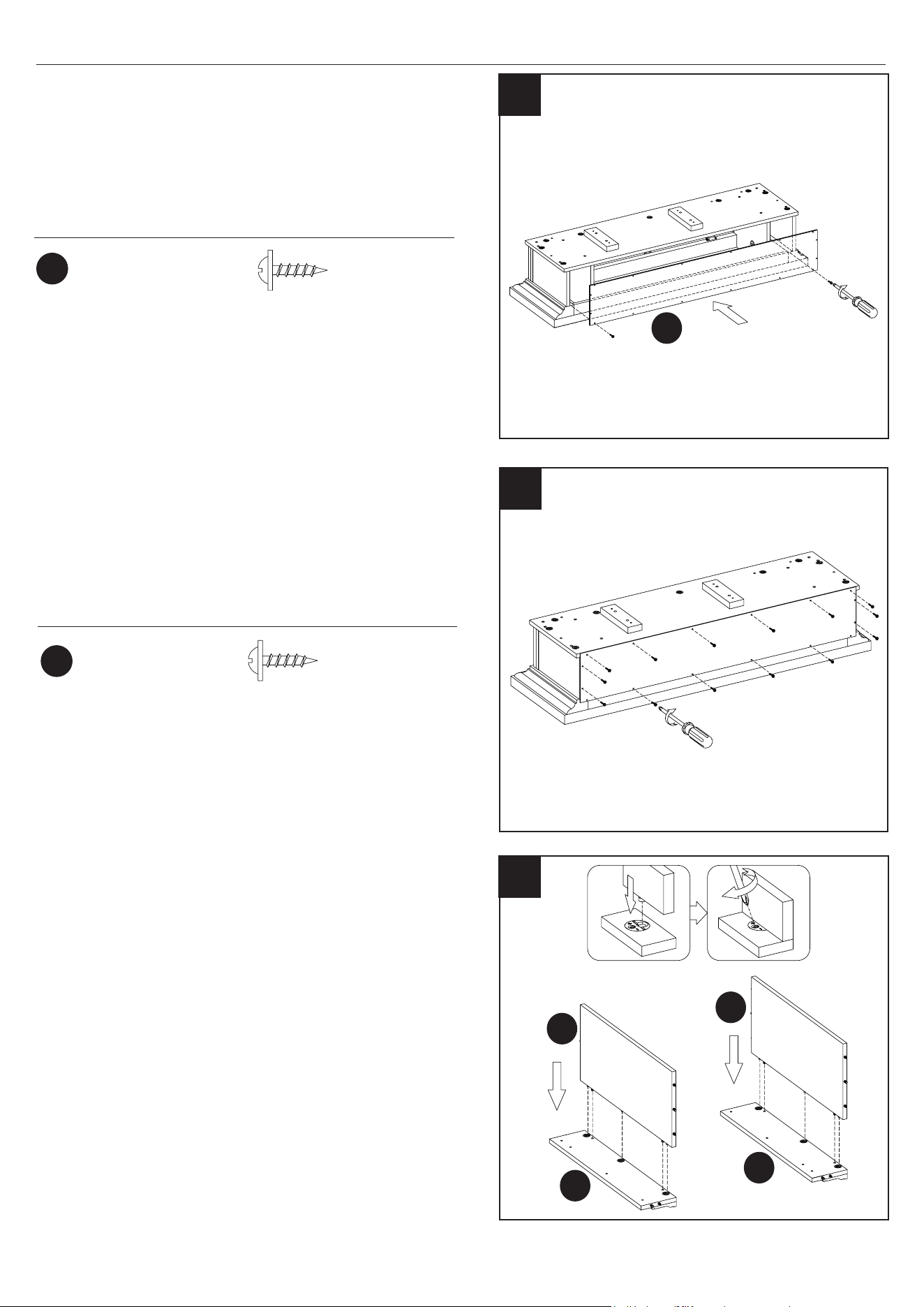
6. Constructing the Side Partitions
• Attach Left Upper Side Panel (H) to Left Upper
Front Panel (F), inserting the pre-installed
hardware on the edges of Left Upper Side Panel
(H) into the pre-drilled holes on Left Upper Front
Panel (F).
• Repeat these steps to attach the Right Upper
Side Panel (K) to Right Upper Front Panel (J).
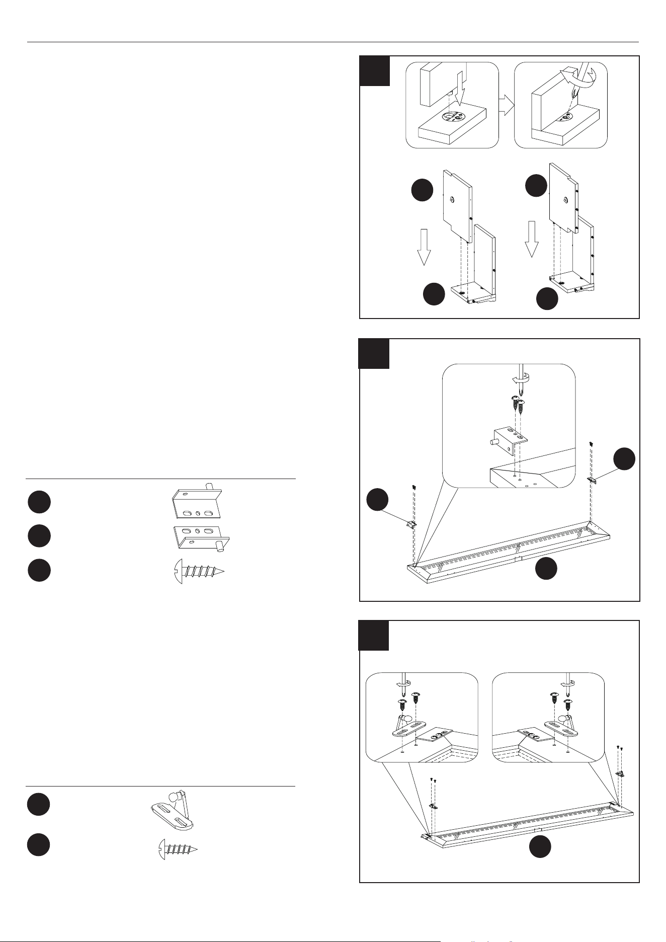
7
7. Attaching the Gas Springs
• Attach the Gas Springs (EE) to the Left Upper
Partition (I) and the Right Upper Partition (L),
using screws (FF).
L
I
EE
FF
Hardware Used
x 2
x 6
Ø3.5x12mm
Screw
Gas Spring
6
H
F
K
J
12
28WM373 REV2.0
ASSEMBLY INSTRUCTIONS
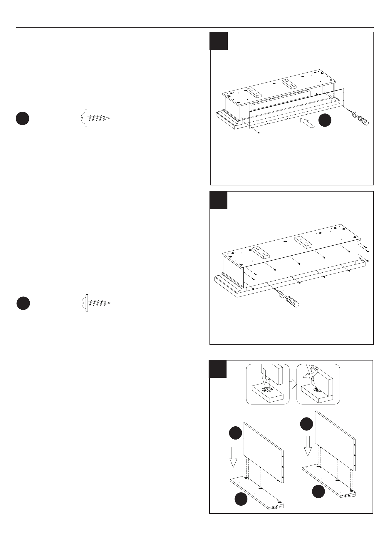
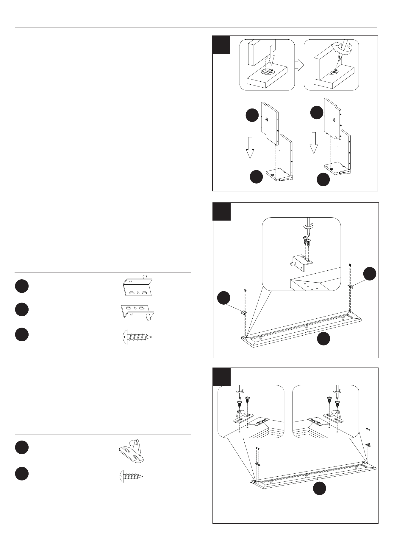
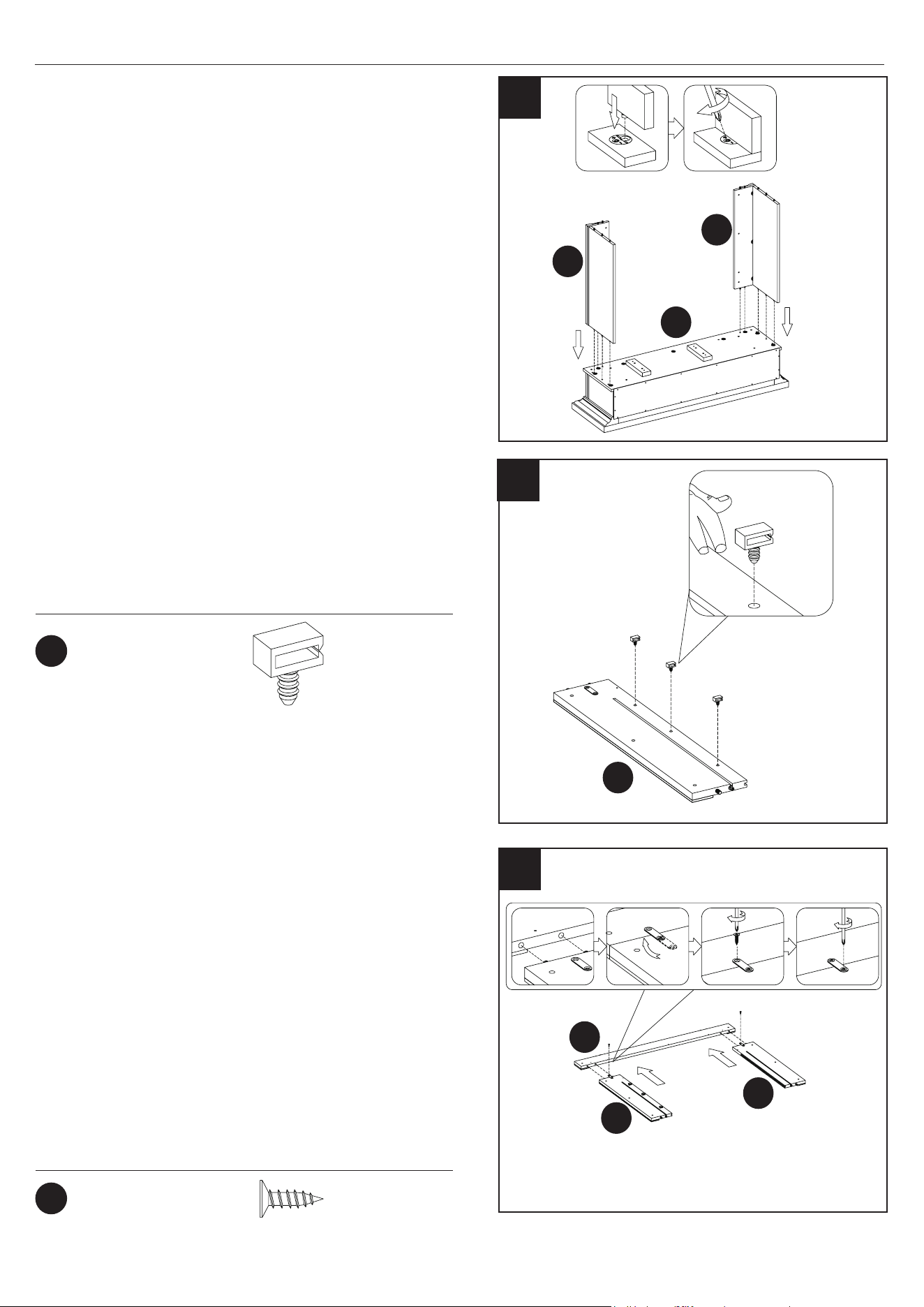
8. Constructing the Side Partitions
• Attach Left Upper Partition (I) to Left Upper
Front Panel (F), inserting the pre-installed
hardware on the edges of Left Upper Partition
(I) into the pre-drilled holes on Left Upper Front
Panel (F).
• Repeat these steps to attach the Right Upper
Partition (L) to Right Upper Front Panel (J).
9
GG
HH
FF
Hardware Used
x1
x1
x4
9. Preparing the Flip Down Door
• Prepare the Flip Down Door (M) by attaching
the Right Pin Hinge (GG) and the Left Pin Hinge
(HH), using Screws (FF) as shown.
10. Preparing the Flip Down Door
• Continue preparing the Flip Down Door (M) by
attaching the Gas Springs (EE), using Screws
(FF) as shown.
10
Hardware Used
M
M
Right Pin Hinge
Left Pin Hinge
EE
FF
x 2
x 4
Ø3.5x12mm
Screw
Gas Spring
Ø3.5x12mm
Screw
L
I
8
F
J
HH
GG
13
28WM373 REV2.0
ASSEMBLY INSTRUCTIONS
Hardware Used
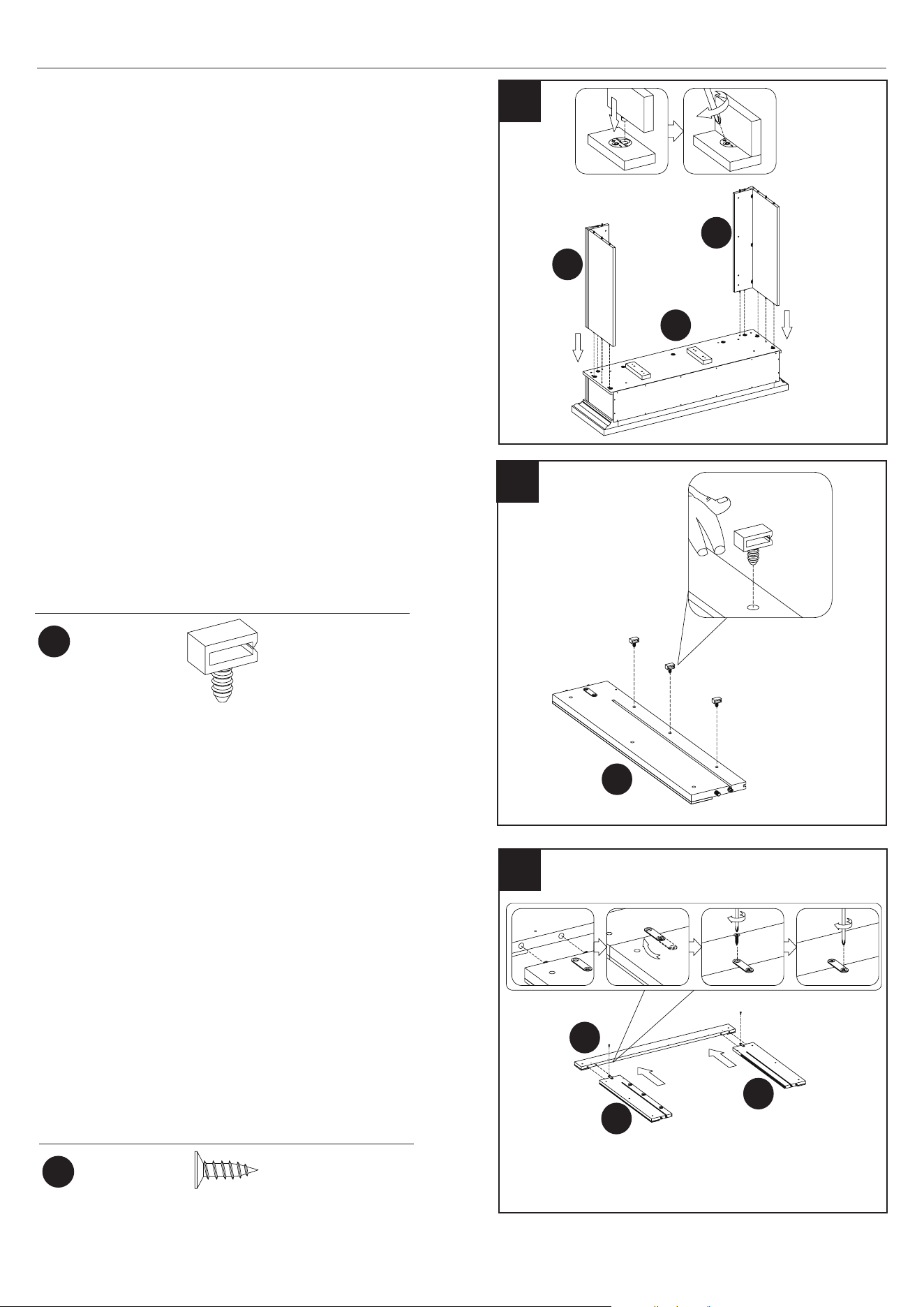
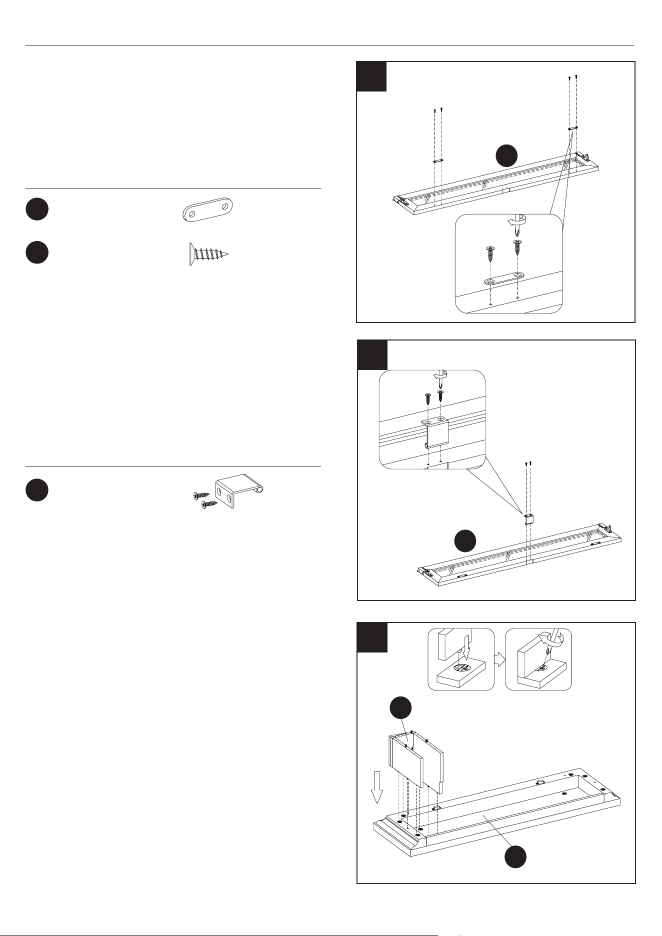
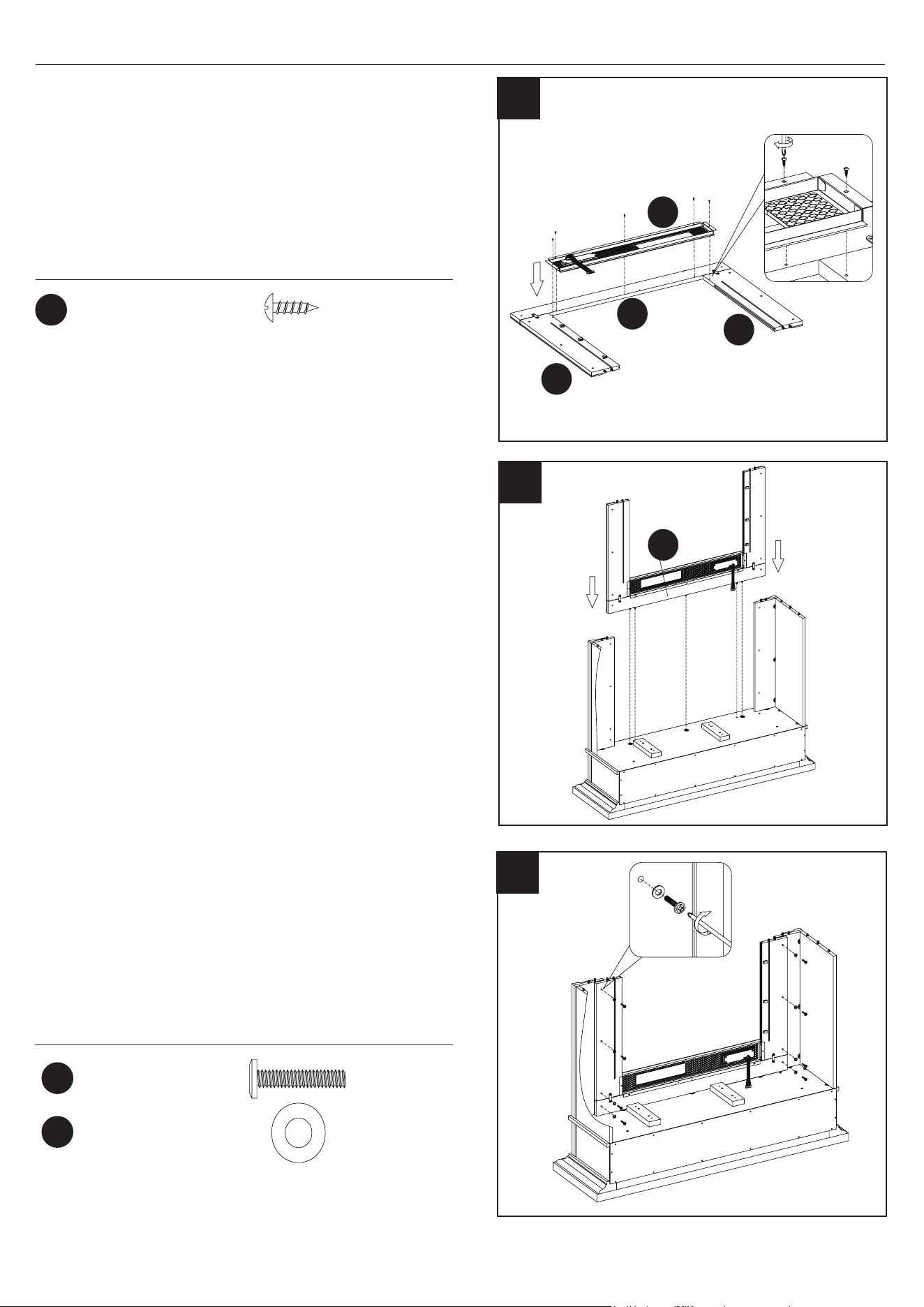
11. Preparing the Flip Down Door
• Continue preparing the Flip Down Door (M) by
attaching the Metal Plates (SS) to the upper edge
of the Flip Down Door as shown with Screws (TT).
11
M
SS
TT
x 2
x 4
Ø3x12mm
Screw
Metal Plate
II
Hardware Used
x 1
12
M
12. Preparing the Flip Down Door
• Continue preparing the Flip Down Door (M) by
attaching the Handle (II) to the upper edge of the
Flip Up Door as shown with the included screws.
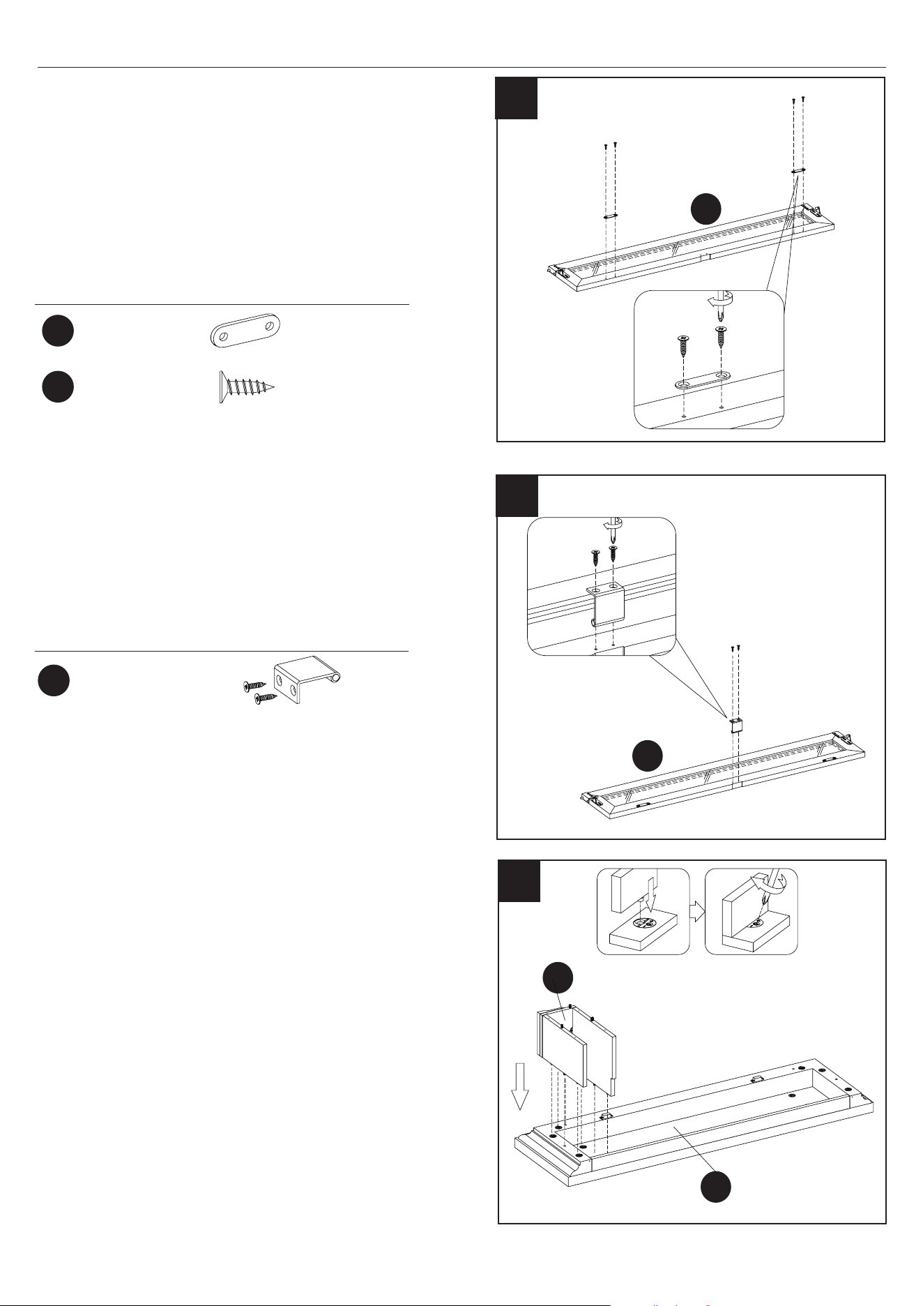
13. Connecting Left Upper Panel Assembly to
the Top Panel
• Attach the Left Upper Panel Assembly to the
Top Panel (G) by inserting the hardware into
the predrilled holes in the top panel, as shown.
Handle (with screw)
F
13
G
14
28WM373 REV2.0
ASSEMBLY INSTRUCTIONS
M
M
14. Connecting Flip Down Door to the Left
Upper Panel Assembly
• Connect the Flip Down Door (M) to the Left Upper
Panel Assembly by inserting the pin hinges into
the predrilled holes in the side of Left Upper Panel
Assembly.
15. Connecting Right Upper Panel Assembly to
the Top Panel
• Connect Right Upper Panel Assembly to the Flip
Down Door (M) by aligning the predrilled holes in
the side of Right Upper Panel Assembly with the
pin hinges in the Flip Down Door (M).
• Attach the Right Upper Panel Assembly to the
Top Panel (G) by inserting the hardware into the
predrilled holes in the top panel, as shown.
14
15
G
G
J
JJ
Hardware Used
x 10
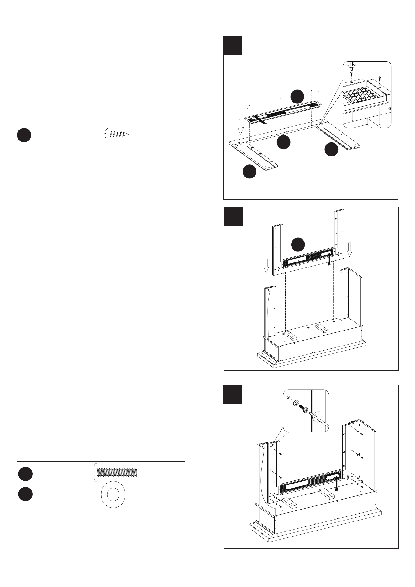
16. Attaching the Fixed Shelf
• Attach the Fixed Shelf (N) to the upper assembly
using Screws (JJ) and a Phillips screwdriver to
attach the shelf as shown.
Ø4x50mm
Screw
16
N
15
28WM373 REV2.0
ASSEMBLY INSTRUCTIONS
O
KK
Hardware Used
x 2
17
17. Aligning the Upper Back Panel
• Align the Upper Back Panel (O) with the upper
assembly attaching Screws (KK) to the corners
rst.
Ø3x12mm
Screw
18. Securing the Upper Back Panel
• Attach the Upper Back Panel (O) to the upper
assembly by securing all Screws (KK) with a Phil-
lips screwdriver as shown.
KK
Hardware Used
x 14
Ø3x12mm
Screw
19
P
Q
R
S
19. Constructing the Fireplace Front
• Attach Left Side Panel (Q) to Left Lower Front
Panel (P), inserting the pre-installed hardware on
the edges of Left Side Panel (Q) into the
pre-drilled holes on Left Lower Front Panel (P).
• Repeat these steps to attach the Right Side Panel
(S) to Right Lower Front Panel (R).
18
16
28WM373 REV2.0
ASSEMBLY INSTRUCTIONS
20. Attaching the Side/Front Panel Assemblies
• Align the pre-installed hardware on the edges of
the left side assembly (Left Side Panel (Q) and
Left Lower Front Panel (P)) with the pre-drilled
holes on the underside of the Fixed Shelf (N) to
join the left side assembly with the upper
assembly.
• Secure the main assembly to the replace
surround by tightening the hardware with a
Phillips screwdriver as shown.
• Repeat these steps for the right side assembly
(Right Side Panel (S) and Right Lower Front
Panel (R)).
N
Q
S
20
TT
UU
Hardware Used
Hardware Used
x2
x3
22. Assembling the Inner Surround Panels
• Align pre-drilled holes at the top edges of Left
Surround Panel (T) and Right Surround Panel
(V) with the pre-installed hardware on the Upper
Surround Panel (U). Push together.
• Locate the pre-attached metal brackets found on
the Left and Right Surround Panels (T and V) and
rotate to span across the edges to the Upper
Surround Panel (U).
• Secure each bracket across each joint with a
Screw (TT) and Phillips screwdriver.
Ø3x12mm
Screw
Wire Clips
V
21
21. Attaching the Wire Clips
• Insert Wire Clips (UU) into pre-drilled holes in
the rail of the Right Surround Panel (V), pushing
them in by hand.
V
T
U
22
17
28WM373 REV2.0
ASSEMBLY INSTRUCTIONS
23
EA
23. Assembling the Fireplace
• Locate the Front Panel with Control Button (EA).
• Using Screws (FF), secure the Front Panel with
Control Button (EA) inside the inner surround
assembly (T, U, and V) as shown.
FF
Hardware Used
x5
Ø3.5x12mm
Screw
U
V
T
25. Securing the front Fireplace Surround to the
Main Assembly
• Secure the front Fireplace Surround to the main
assembly by tightening the hardware (LL and MM)
with a Phillips screwdriver as shown.
24. Attach the front Fireplace Surround to the
Main Assembly
• Align the pre-installed hardware on the edges of
the main assembly with the pre-drilled holes on
the replace surround.
• Secure the main assembly to the replace
surround by tightening the hardware with a Phillips
screwdriver as shown.
LL
MM
Hardware Used
x8
x8
Ø6.3x30mm
Bolt
Ø16mm
Washer
24
U
25
18
28WM373 REV2.0
ASSEMBLY INSTRUCTIONS
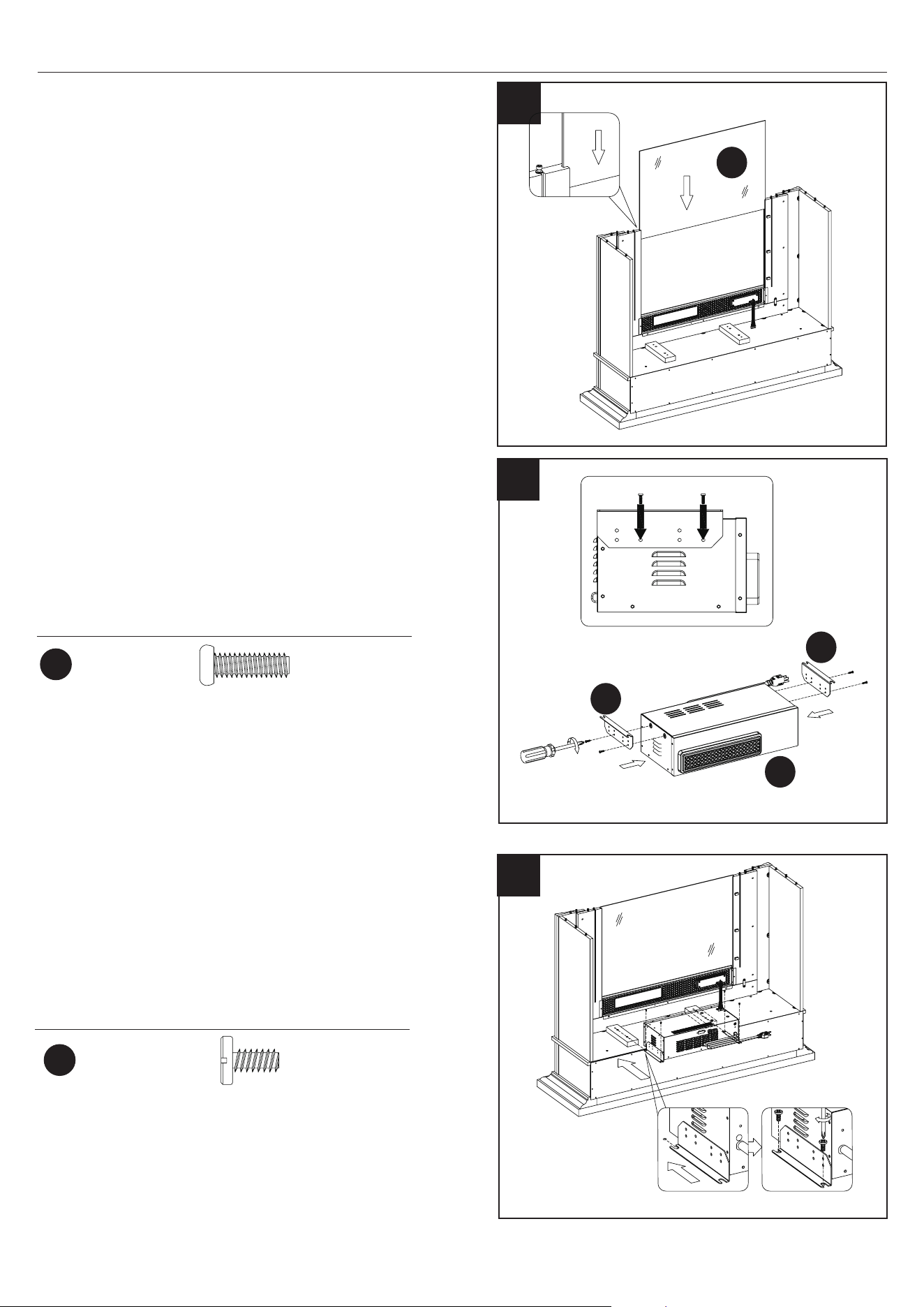
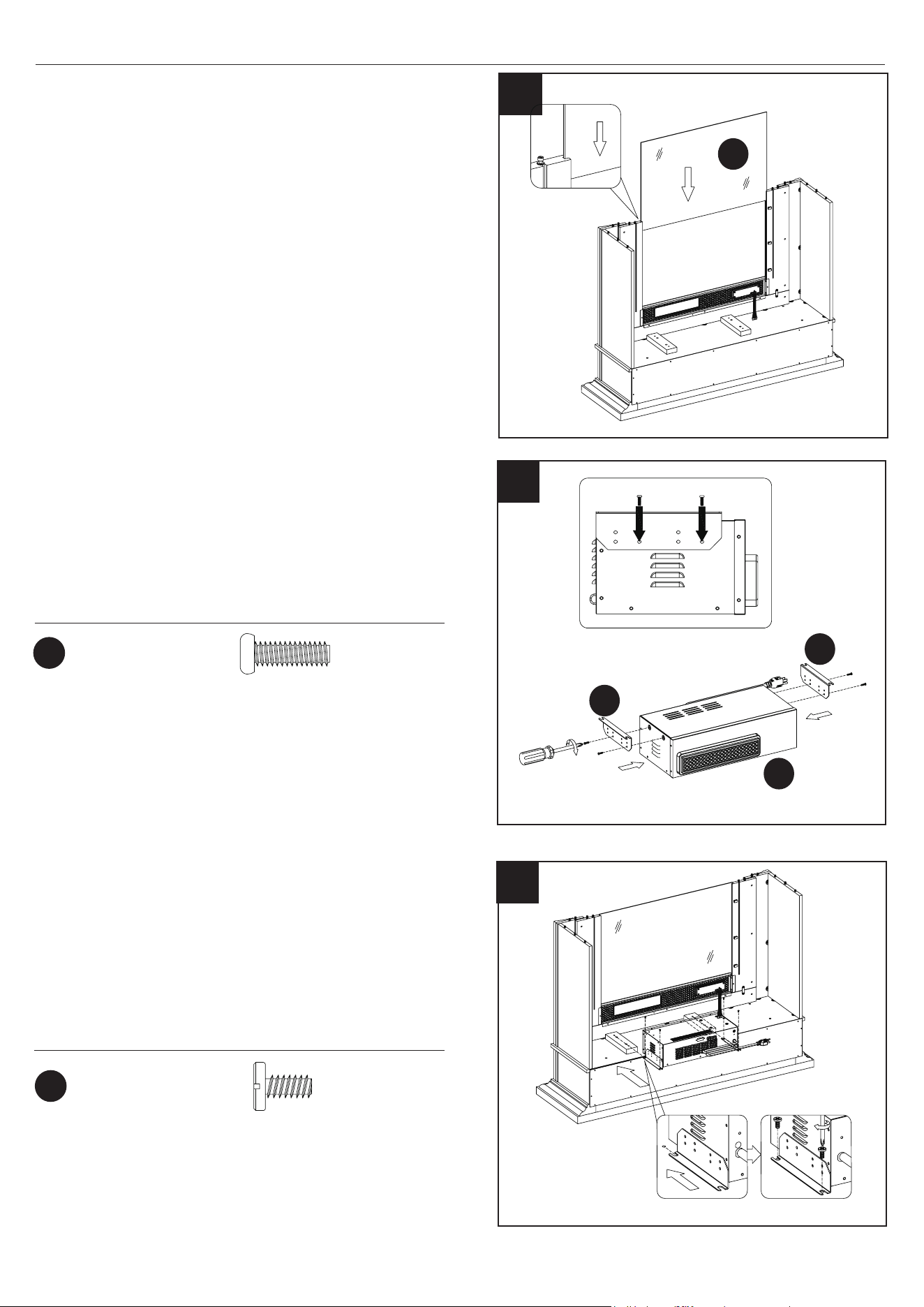
26. Placing the Glass Front
• Locate the Front Glass Panel (W).
• Carefully insert the Front Glass Panel (W) into the
grooves of the surround rails as shown. Slide all
the way in until the glass meets the bottom of the
Control Support Panel.
26
W
W
EF
EF
EB
27
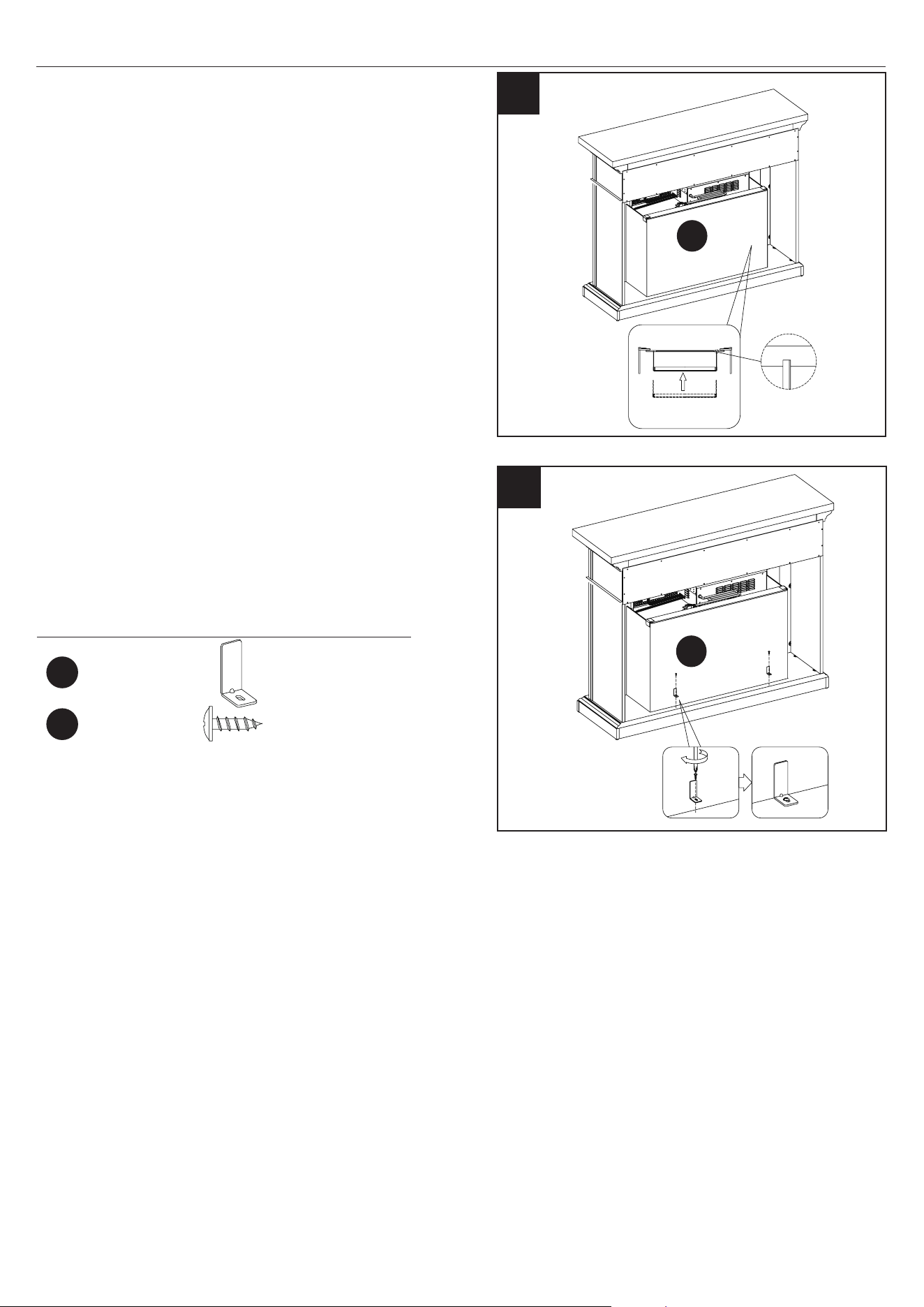
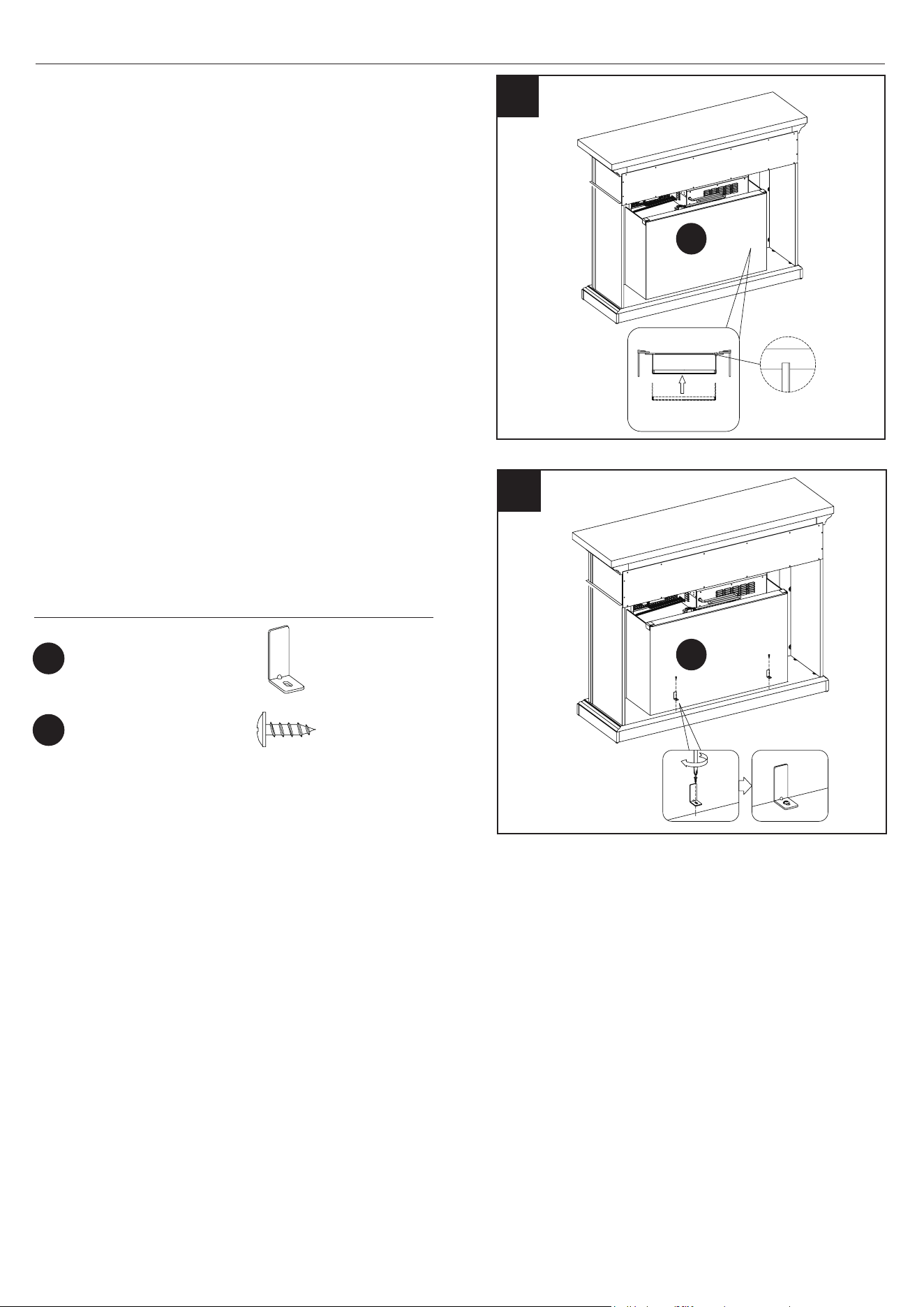
27. Attaching the Insert Brackets
• Locate the mounting Brackets (EF) and secure
to each side of the Heater Box (EB) using Bolts
(NN), as shown.
28. Installing the Fireplace Heater
• Insert Bolts (BB) through the holes in the mounting
L Brackets (EF) and into the Left and Right Side
Partitions to attach the Heater Box (EB) to the Left
and Right Side Partitions.
NN
Hardware Used
Hardware Used
x4
Ø4x12mm
Bolt
Ø6.3x12mm
Bolt
BB
x 4
28
19
28WM373 REV2.0
ASSEMBLY INSTRUCTIONS
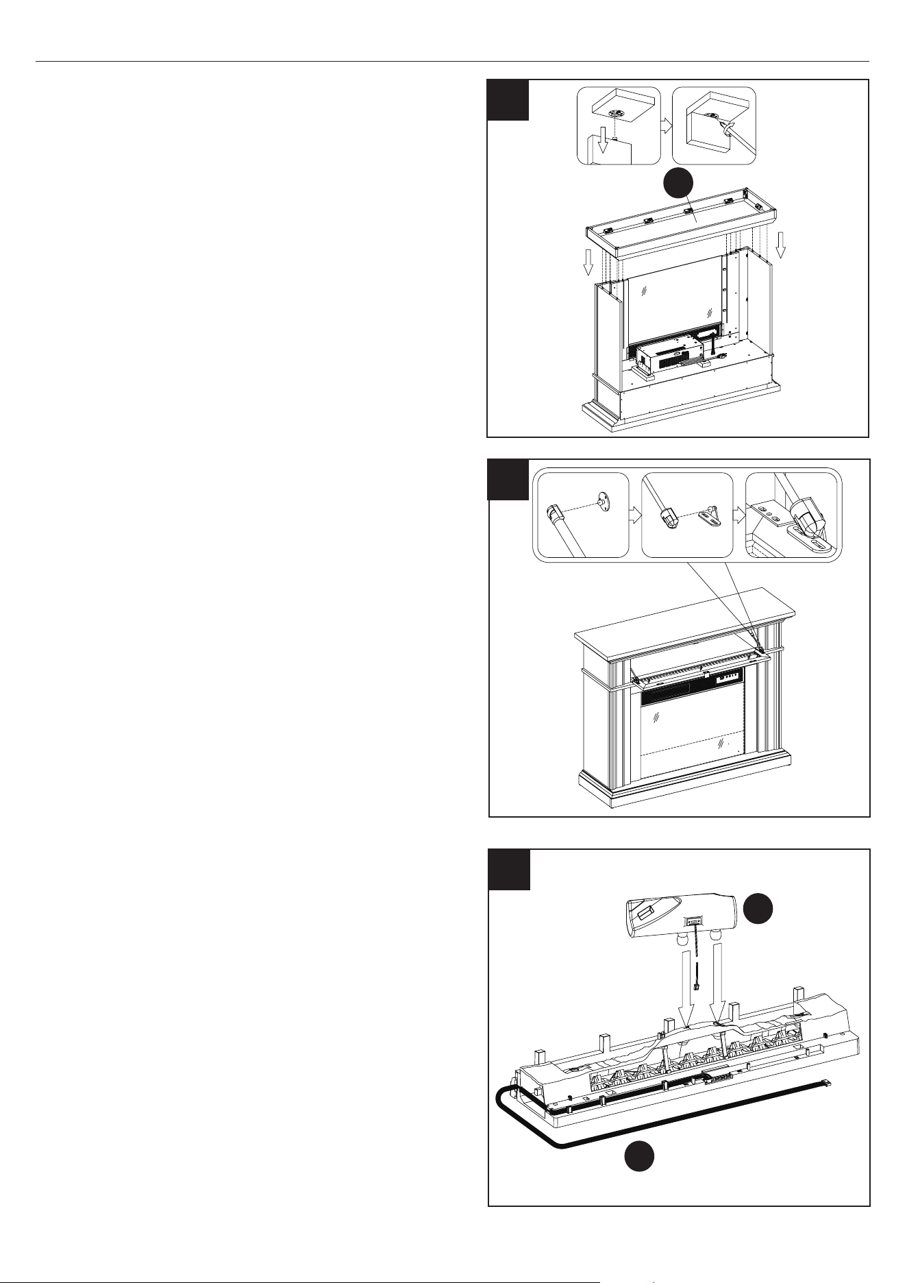
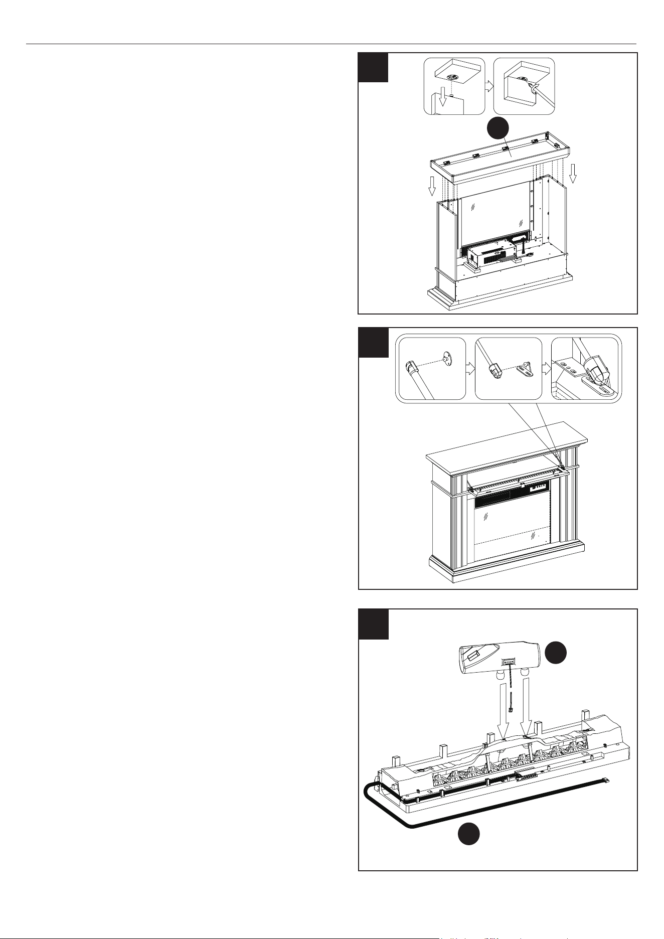
29. Attaching the Base
• Align the predrilled holes in Base (A) with the
hardware on the edges of the main assembly.
• Secure the Base to the main assembly by
tightening the hardware with a Phillips screwdriver
as shown.
29
A
30
30. Attaching the Gas Springs
• Attach the gas springs to the edges of the Flip Up
Door as shown.
EL
31
EI
31. Assembling the Log Set
• Place the Log Set Middle (EL) into the Ember Bed
(EI) as shown.
20
28WM373 REV2.0
ASSEMBLY INSTRUCTIONS
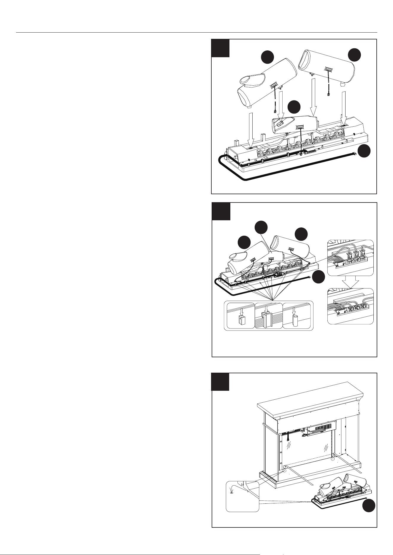
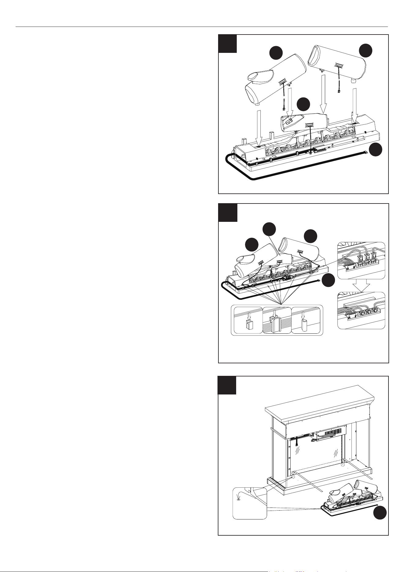
32. Assembling the Log Set
• Place the Log Set Left (EJ) and Log Set Right
(EK) into the Log Set Middle (EL) and Ember Bed
(EI) as shown.
EK
EJ
EL
32
EI
34. Assembling the Fireplace
• Place the assembled log set into the back of the
unit behind the glass panel.
• Push the tabs beneath the log set into the holes
on the bottom panel.
EI
EL
EJ
EK
33
33. Assembling the Log Set
• Route the wires of the Log Set Left (EJ) , the
Log Set Right (EK) and Log Set Middle (EL) down
the back of the Ember Bed (EI) and into the
receiving tabs to secure in place. Refer to the
lower diagram.
• Gently plug the cords from the Log Set Left
(EJ), the Log Set Right (EK) and Log Set Middle
(EL) into the ports as shown. Ensure the cords are
plugged in straight.
EI
34
21
28WM373 REV2.0
ASSEMBLY INSTRUCTIONS
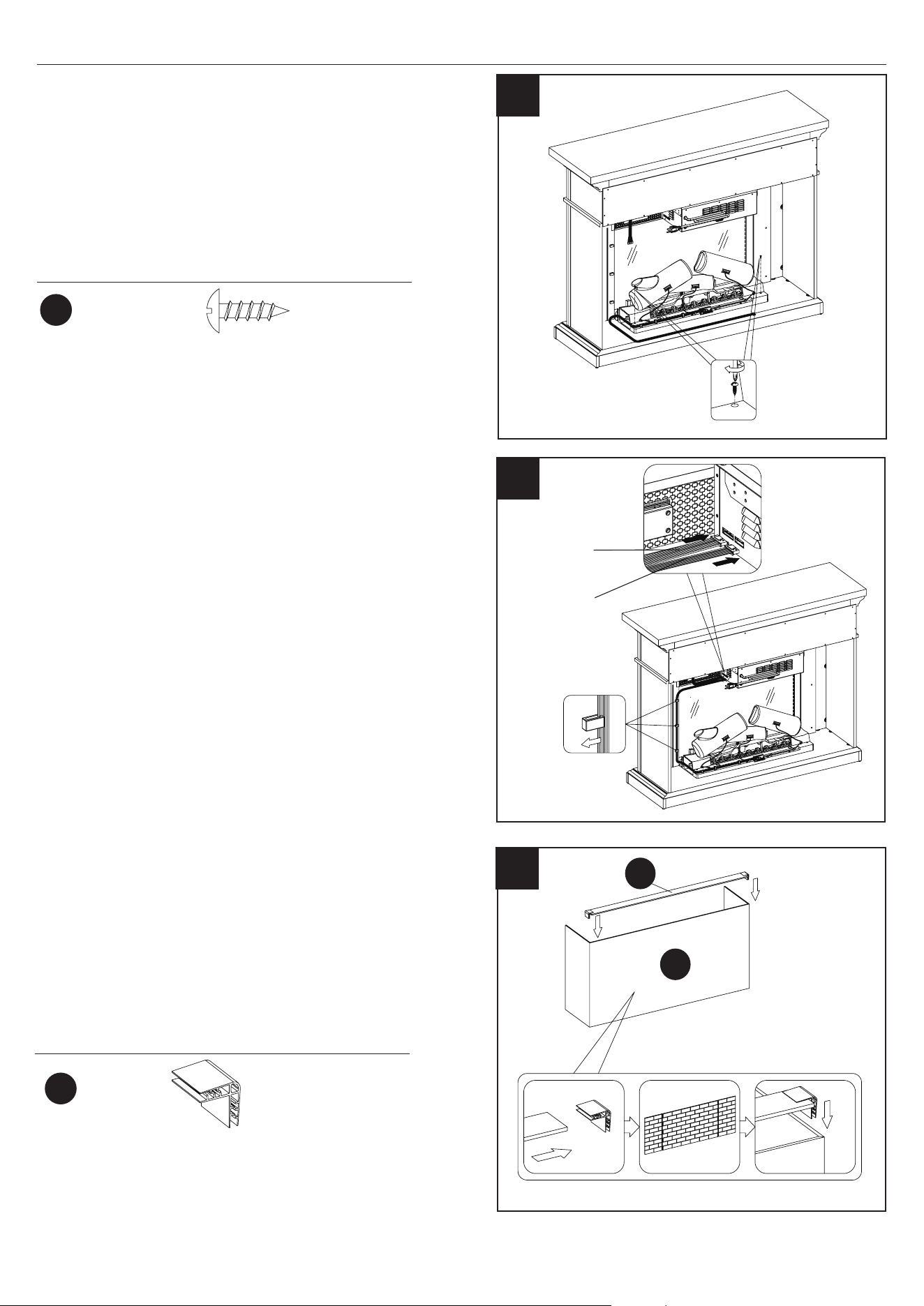
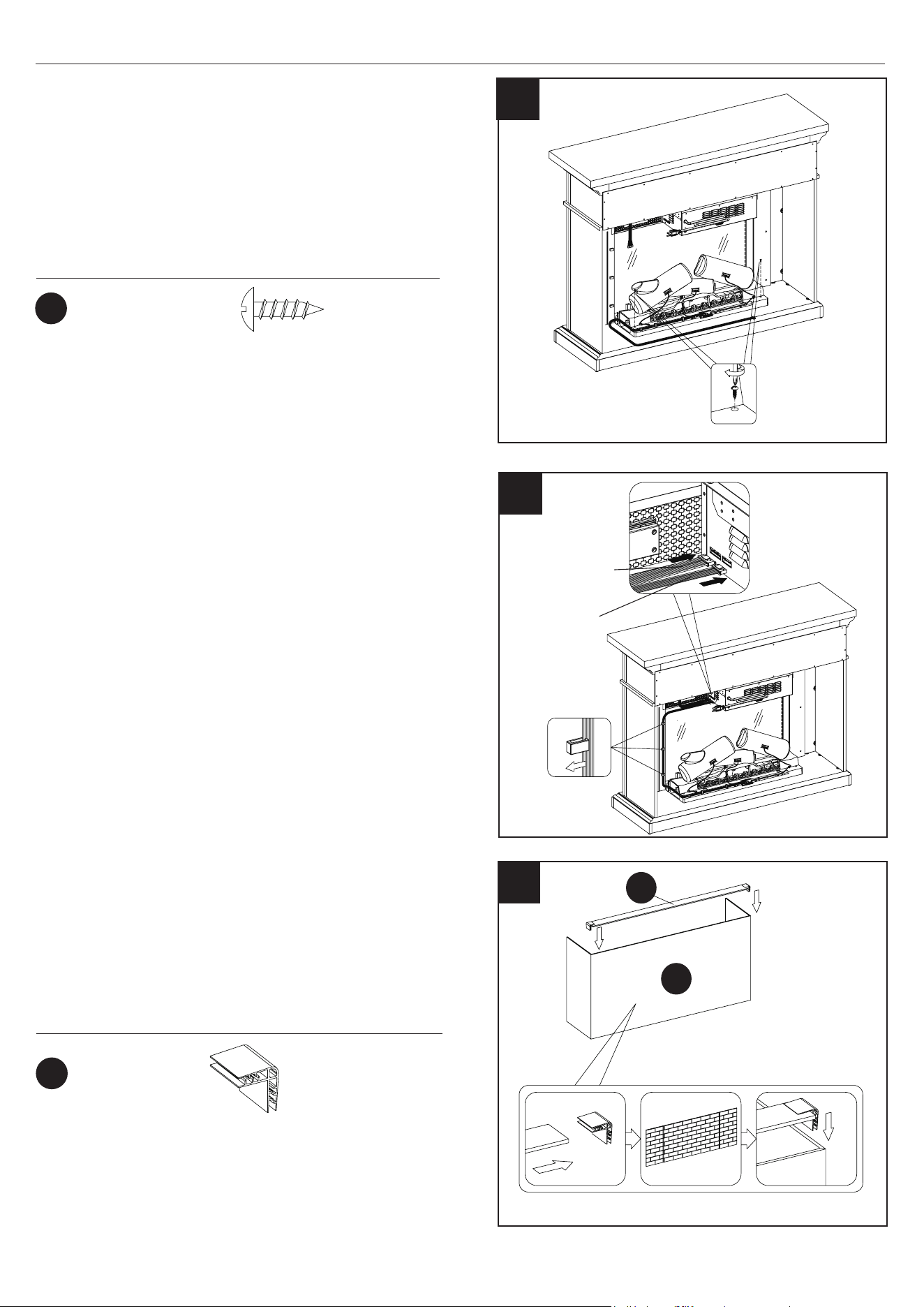
35. Securing the Log Set
• Once the log set is in place, secure with Screws
(FF) through the bottom of the log set and into the
base.
FF
Hardware Used
x2
Ø3.5x12mm
Screw
35
36
36. Connecting the Fireplace Wiring
• Connect control panel cable to heater.
• Insert the Ember Bed Connection Wire into the
heater.
• Route the Ember Bed Connection Wire down the
side surround rail and along the back of the log
set, securing it in place with the clips as shown.
control panel
cable
Ember Bed
Connection Wire
Hardware Used
x2
OO
Y
X
37
37. Placing the Fireplace Background
• Connect the Back Panel Frame (Y) to the Electric
Fireplace Back Panel (X) using Clips (OO), as
shown.
Clip
22
28WM373 REV2.0
ASSEMBLY INSTRUCTIONS
38. Positioning the Fireplace Background
• Position the Electric Fireplace Back Panel (X)
behind the electric replace and centered as
shown.
X
38
X
39
39.Securing the Fireplace Background
• Secure the Electric Fireplace Back Panel (X)
to the Base with the Metal Brackets (PP) and
Screws (QQ), as shown.
Hardware Used
x2
x2
PP
QQ
Ø4x15mm
Screw
Metal Bracket
23
28WM373 REV2.0
ASSEMBLY INSTRUCTIONS
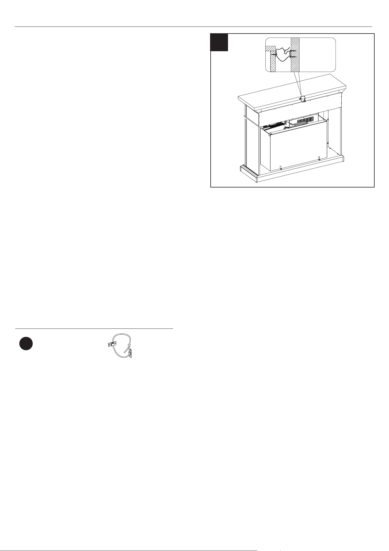
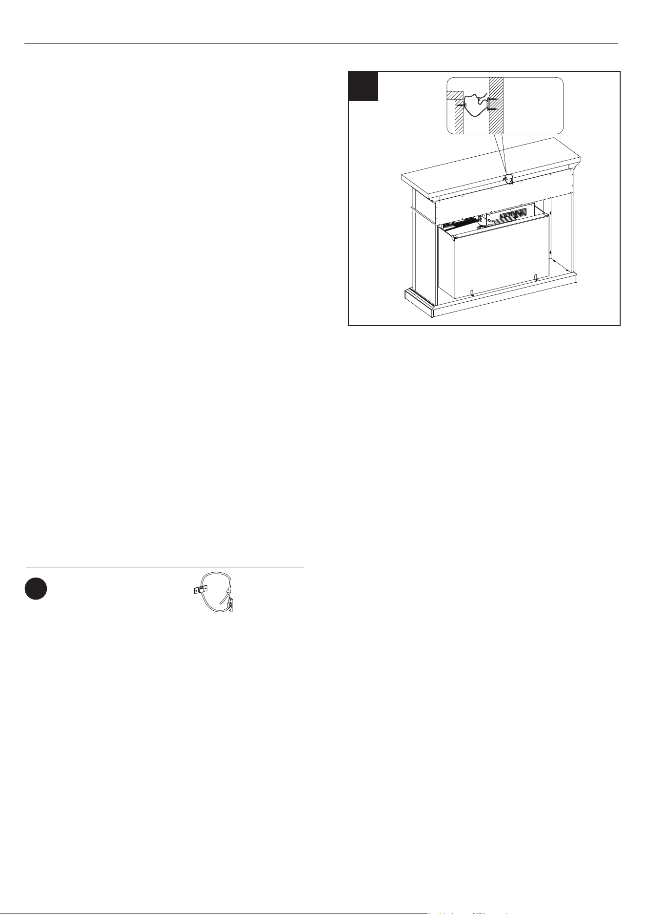
40. Installing the Tip Restraint Hardware
• When the Tipping Restraint Hardware (RR) is
properly installed, it can provide protection
against unexpected tipping of the Unit due to small
tremors, bumps or climbing.
• Each Tipping Restraint Hardware (RR) includes one
Unit Anchor, one Wall Anchor, one Anchor Tether,
and four Anchor Screws. Use these to complete the
following steps for a proper installation.
• Locate a secure wall stud behind the unit closest to
left side.
• Align the Unit Anchor with a wall stud and attach
to the Unit with two Anchor Screws using a Philips
Screwdriver. The Anchor Screws must pass through
the Top Assembly for proper installation.
• Align the Wall Anchor in the center of the wall stud,
at level with the Unit Anchor, and with two Anchor
Screws using a Philips Screwdriver.
• On the Anchor Tether, detach the cable from the
connector and loop the loose cable through the
eyelets on the Wall Anchor and Unit Anchor.
Reattach the loose cable to the connector, but do not tighten.
• Locate a secure wall stud behind the unit closest to the right side and repeat the steps above.
• Tighten both Anchor Tethers by pulling the cable the through connector.
NOTE: Installation of the Tipping Restraint Hardware (RR) will provide a small space between the
wall and the unit. This will allow you to run power cords and connector cables to your
television or other devices placed on top of the unit.
WARNING: Installing the Tipping Restraint Hardware will help prevent accidents or damage to the
unit.
Hardware Used
x1
RR
Tipping Restraint
Hardware
40
24
28WM373 REV2.0
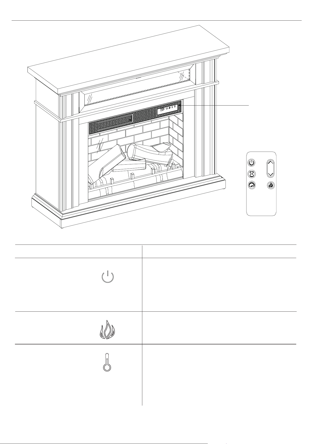
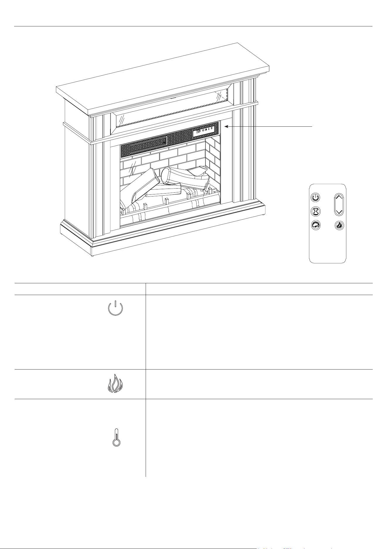
OPERATING INSTRUCTIONS
CONTROL
PANEL
LOCATION
FUNCTION
FLAME
POWER
There are 5 brightness levels that can be selected
and OFF (00) setting. Settings F5 - F1 decrease in
brightness.
The POWER button supplies power to all the
functions of the heater. Pressing the POWER button
again will put the heater in standby mode.
Holding the Power button on the control panel for 10
seconds will disable the heater function.
Press the heater button on the control panel to turn
on/o (00) and adjust the heater setting.
To change between °F and °C, press and hold the
HEATER button on the control panel for 3 seconds.
The thermostat setting range is 62°F - 82°F
( 17°C - 27°C) or continuously ON.
HEATER
ICON DESCRIPTION
25
28WM373 REV2.0
OPERATING INSTRUCTIONS
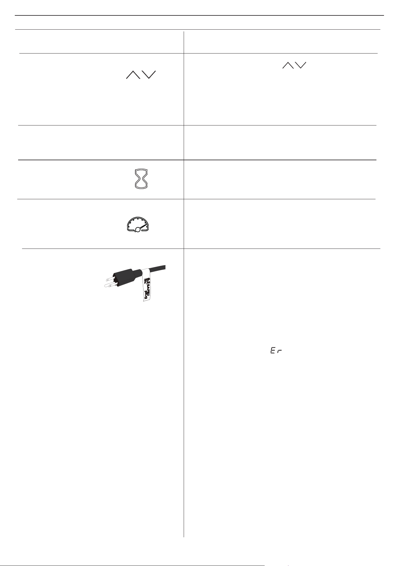
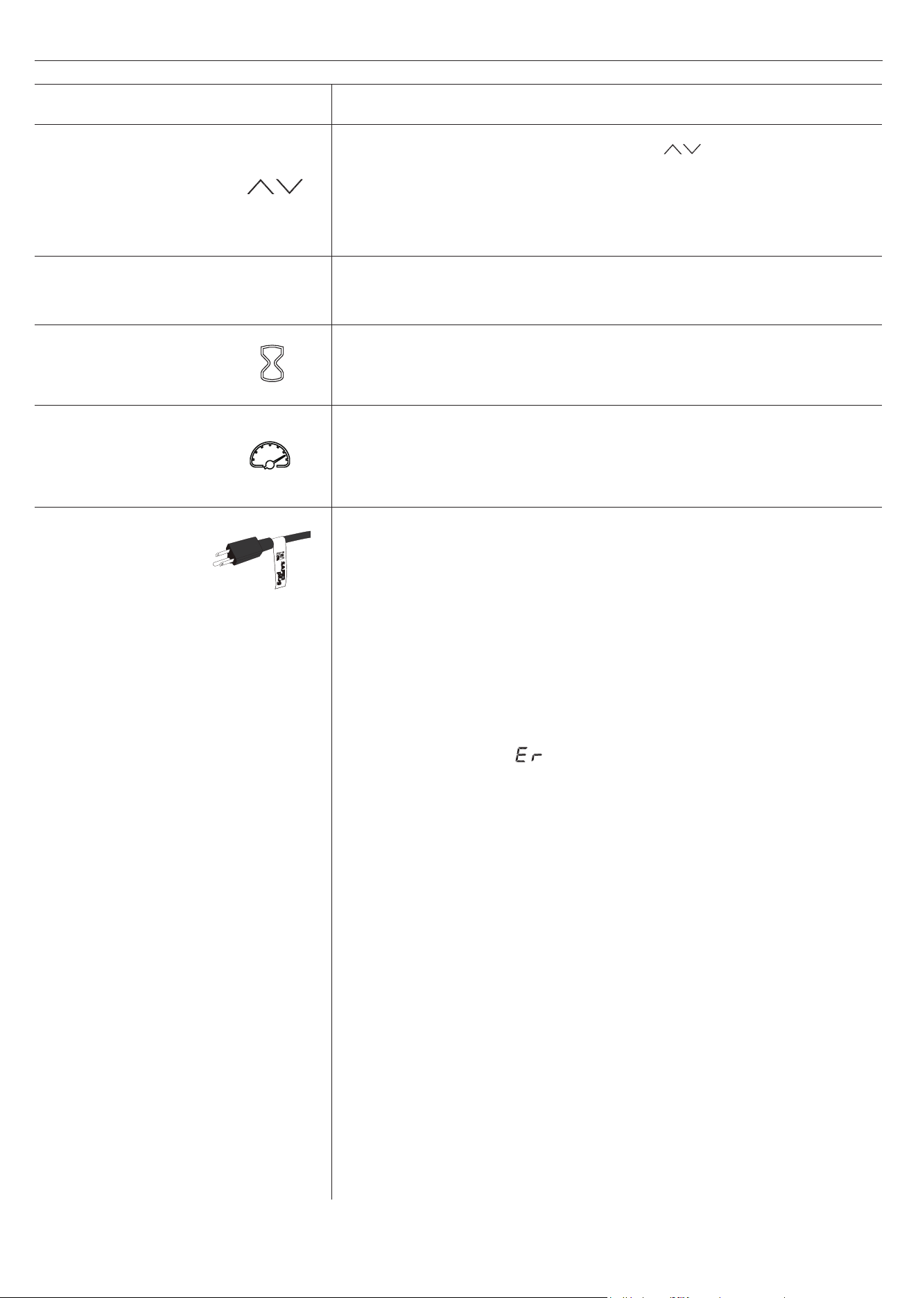
FUNCTION
Pressing the timer button will cycle through the
timer settings: 30 minutes, 1 Hour, 2H, 3H, 4H, 5H,
6H, 7H, 8H, 9H and OFF (00).
The ame speed is only adjustable from the remote
control. Each ame setting has 5 speed options
available. Setting S1 is slowest ranging up to set-
ting S5 which is the fastest.
TIMER
ICON DESCRIPTION
FLAME SPEED
This product is equipped with a Safer Plug
®
; an
advanced safety device that helps prevent electrical
res caused from faulty outlets.
Overloading of outlets, adapters and surge protectors
may cause overheating, damage, and increase risk of
res. Safer Plug
®
continuously monitors the tempera-
ture in the plug and outlet and will turn o the heater
to prevent unsafe outlet overheating.
If the Safer Plug
®
cuts the power due to unsafe con-
ditions it will show an “ ”message on the screen. If
this occurs the Safer Plug
®
has prevented a poten-
tially unsafe condition.
To reset the device if this occurs, rst allow the plug
to cool down. Once the plug has cooled down, unplug
the device and wait 5 seconds, then plug back in and
continue to use normally.
If the Safer Plug
®
continues to activate your out-
let may be faulty. Check your heater cord and plug
connections. Faulty wall outlet connections or loose
plugs can cause the outlet or plug to overheat. Be
sure the plug ts tight in the outlet. Heaters draw
more current than small appliances, so overheating
of the outlet may occur even if it has not occurred
with the use of other appliances. During use check
frequently to determine if your plug, outlet or face-
plate is HOT! If so, discontinue use of the heater and
have a qualied electrician check and/or replace the
faulty outlet(s).
SAFER PLUG
®
The up and down buttons “ ” on the remote
will increase / decrease temperature setting.
The thermostat setting range is 62°F - 82°F
( 17°C - 27°C) or continuously ON.
The thermostat is adjustable by 2°F or 1°C
increments.
TEMPERATURE IN-
CREASE / DECREASE
COOL DOWN CYCLE
Before the heater powers o, the fan will continue to
run for a period of time to cool down the internal
parts.

26
28WM373 REV2.0
TROUBLESHOOTING
PROBLEM POSSIBLE CAUSE CORRECTIVE ACTION
Display shows“ ”
The thermostat sensor is
broken or disconnected.
Unplug the replace, remove the back panel of the
heater box and check that the thermostat is plugged
into the main circuit board. If this does not solve the
problem contact customer service for a replacement
thermostat sensor.
Display shows“ ”
The thermostat sensor
short circuited.
Contact customer service for a replacement
thermostat sensor.
Display shows " "
Manual Reset overheat
protection has triggered.
Inspect the heater and check that the air inlets
and outlets are not blocked as this may cause
overheating. Unplug the heater for 30 minutes and
allow it to cool down. Replug and operate. Monitor
the heater for signs of overheating. If the problem
persists, discontinue use of the heater and contact
customer service.
Display shows “ ” Normal operation.
Check your heater cord and plug connections.
Faulty wall outlet connections or loose plugs can
cause the outlet or plug to overheat. Be sure the
plug ts tight in the outlet. Heaters draw more
current than small appliances, overheating of the
outlet may occur even if it has not occurred with the
use of other appliances.
During use check frequently to determine if your
plug outlet or faceplate is HOT! If so, discontinue
use of the heater and have a qualied electrician
check and/or replace the faulty outlet(s).
Heater does not blow
warm air.
Cool down cycle.
Normal operation, will continue to
run for less than
one minute
before shutting down. Times will vary
based on temperatures. During this time cool air will
blow.
No power, logs do not
glow.
No power to the unit
Check that unit is plugged into a standard 120V
outlet. Press power button several times, make sure
power is set at “ON” position.
Logs glow, but no
ame eect.
Flame eect turned o Press ame button several times.
Heater does not blow
warm air.
Thermostat setting is
preventing heater from
turning on.
Adjust the temperature settings to ensure that
the thermostat is set higher than the current room
temperature.
Flame eect works but
heater function does
not and the emberbed
ashes when the heater
button is pressed.
The heater is disabled.
With the power on press and hold the POWER
button on the control panel for 10 seconds. Once
re-enabled the emberbed lights will ash multiple
times.
Remote Control is not
working.
No batteries Change the remote batteries.
Poor Signal
Operate remote transmitter at a slow measured
pace. Measured the remote control buttons with an
even motion and gentle pressure. Repeatedly press-
ing buttons in rapid succession may cause the
transmitter to malfunction.
Distance
Operate the remote at a distance less than 20 feet
from the front of the appliance; point the remote at
the control panel.

27
28WM373 REV2.0
Warning: Changes or modications to this unit not expressly approved by the party responsible
for compliance could void user’s authority to operate the equipment.
NOTE: This equipment has been tested and found to comply with the limits for Class B digital device,
pursuant to part 15 of the FCC Rules. These limits are designed to provide reasonable protection against
harmful interference in a residential installation. This equipment generates,
uses, and can radiate radio frequency energy and, if not installed and used in accordance with
the instructions, may cause harmful interference to radio communications.
However, there is no guarantee that interference will not occur in a particular installation. If this equipment
does cause harmful interference to radio or television reception, which can be determined by turning the
equipment o and on, the user is encouraged to try to correct the interference by one or more of the following
measures:
• Reorient or relocate the receiving antenna.
• Increase the separation between the equipment and the receiver.
• Connect the equipment into an outlet on a circuit dierent from that to which the receiver
is connected.
• Consult the dealer or an experienced radio/TV technician for help.
This device complies with Part 15 of the FCC Rules. Operation is subject
to the following two conditions:
(1) This device may not cause harmful interference, and
(2) This device must accept any interference received, including interference that may cause undesired
operation.
Twin-Star International Inc.
1690 S. Congress Ave., Suite 210, Delray Beach, FL 33445
1-866-661-1218
This Class B digital apparatus complies with Canadian ICES-003.
• Clean the trim using a soft cloth, slightly dampened with citrus oil based product and
bu with a clean soft cloth.
• Citrus oil based products are recommended for cleaning and can be found at supermarkets or
hardware stores.
• WARNING: Electrical outlet wiring must comply with local building codes and other applicable
regulations to reduce the risk of re, electrical shock and injury to persons.
• WARNING: Disconnect power before attempting any maintenance or cleaning to reduce the risk of
re, electrical shock or personal injury.
FCC/IC INFORMATION
CARE AND MAINTENANCE

28
28WM373 REV2.0
The manufacturer warrants that your new Electric Fireplace is free from manufacturing
and material defects for a period of one year from date of purchase, subject to the following conditions
and limitations.
1. Install and operate this appliance in accordance with the installation and operating instructions
furnished with the product at all times. Any unauthorized repair, alteration, willful abuse, accident,
or misuse of the product shall nullify this warranty.
2. This warranty is non-transferable, and is made to the original owner, provided that the purchase
was made through an authorized supplier of the product.
3. The warranty is limited to the repair or replacement of part(s) found to be defective in material or
workmanship, provided that such part(s) have been subjected to normal conditions of use and
service, after said defect is conrmed by the manufacturer’s inspection.
4. The manufacturer may, at its discretion, fully discharge all obligations with respect to this warranty
by refunding the wholesale price of the defective part(s).
5. Any installation, labor, construction, transportation, or other related costs/expenses arising from
defective part(s), repair, replacement, or otherwise of same, will not be covered by this warranty,
nor shall the manufacturer assume responsibility for same.
6. The owner/user assumes all other risks, if any, including the risk of any direct, indirect or
consequential loss or damage arising out of the use, or inability to use the product, except as
provided by law.
7. All other warranties – expressed or implied –with respect to the product, its components and
accessories, or any obligations/liabilities on the part of the manufacturer are hereby expressly
excluded.
8. The manufacturer neither assumes, nor authorizes any third party to assume on its behalf, any
other liabilities with respect to the sale of the product.
9. The warranties as outlined within this document do not apply to non accessories used in
conjunction with the installation of this product.
10. This warranty gives you specic legal rights, and you may also have other rights which vary from
state to state.
This warranty is void if:
a. The replace is subjected to prolonged periods of dampness or condensation.
b. Any unauthorized alteration, willful abuse, accident, or misuse of the product.
c. You do not have the original receipt of purchase.
1-YEAR LIMITED WARRANTY
29
28WM373 REV2.0
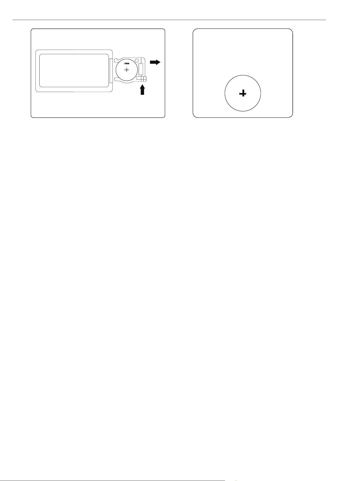
NOTE: Battery disposal
CR2025
Please always dispose of
batteries at a suitable
recycling point.
REPLACING THE REMOTE CONTROL BATTERY:
CAUTION:
• Do not ingest battery.
• Non-rechargeable battery is not to be recharged.
• Battery is to be inserted with the correct polarity.
• Exhausted battery is to be removed from the product.
• Always purchase the correct size and grade of battery most suitable for the intended use.
• Clean the battery contacts and also those of the device prior to battery installation.
• Remove used battery promptly.
• Do not dispose of batteries in re. Batteries may explode or leak.
WARNING: Chemical Burn Hazard. Keep batteries away from children.
This product contains a lithium button/coin cell battery. If a new or used lithium button/coin cell battery is
swallowed or enters the body, it can cause severe internal burns and can lead to death in as little as 2 hours.
Always completely secure the battery compartment. If the battery compartment does not close securely, stop
using the product, remove the batteries, and keep it away from children. If you think batteries might have been
swallowed or placed inside any part of the body, seek immediate medical attention.
a) The cells shall be disposed of properly, including keeping them away from children; and
b) Even used cells may cause injury.
1pcs CR2025 included

30
28WM373 REV2.0
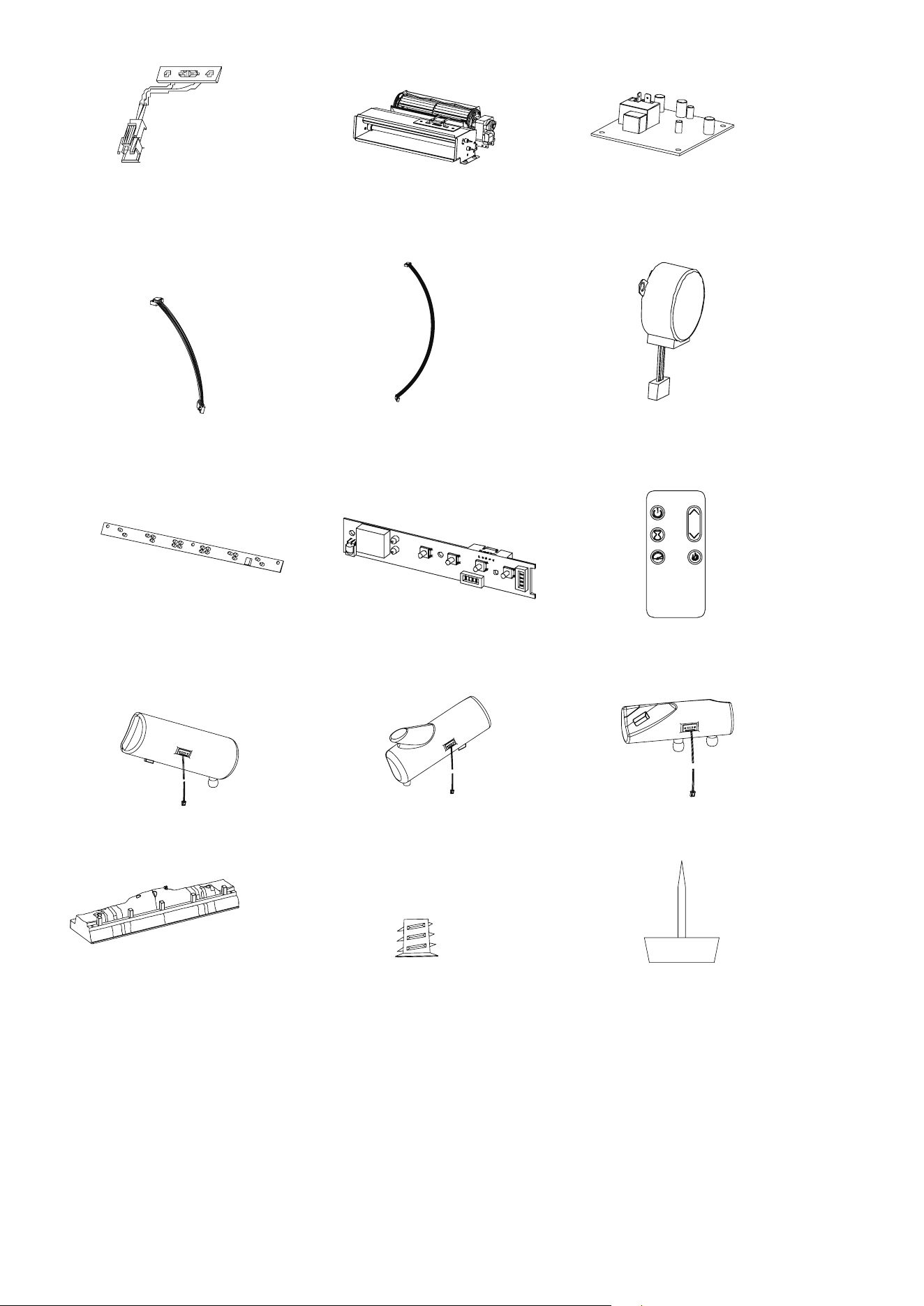
REPLACEMENT PARTS LIST
For replacement parts, call our customer service department at 866-439-9800,
8 a.m. - 8 p.m., EST, Monday - Sunday. You could also contact us at [email protected].
PART PART NAME NO PART NUMBER
1
Thermostat Sensor 1
Y21-S307-P186SS
2
Blower/ Heater Assembly 1
Y21-S307-P01SS
3
Main Circuit Board 1
Y21-S307-P15SS
4 Control Panel Cable
1 Y21-S327-P187SS
5
Ember Bed Connection Wire
1
Y21-S307-P188SS
6
Flame Generator Drive Motor 1
Y21-S307-P189SS
7
Flame Circuit Board 1 Y21-S307-P40SS
8
Control Panel Circuit Board 1
Y21-S307-P32SS
9
Remote Control
1 P185
10 Log Set Left 1 Y21-S307-P20LSS
11 log Set Right 1 Y21-S307-P20RSS
12 Log Set Middle 1 Y21-S307-P20MSS
13 Ember bed 1 Y21-S327-P21SS
14 Threaded Insert 40 PH-THRZNC001
15 Floor Glide 4 PH-GLDBRW001
31
28WM373 REV2.0
Printed in Vietnam
1
6
3
5
7
10
14
13
8
9
4
2
11
15
12
ARTÍCULO # 5228467
MODELO # 149148 / 28WM373-TPF11
SS23021
¿Preguntas, problemas, piezas faltantes? Antes de volver a la tienda, llame a
nuestro Departamento de Servicio al Cliente al 1-866-439-9800, de lunes a domingo
de 8 a.m. a 8 p.m., hora estándar del Este. También puede ponerse en contacto con
nosotros en [email protected].
ALLEN+ROTH y el diseño del logotipo son
marcas comerciales o marcas registradas
de LF, LLC.
Todos los derechos reservados.
Número de serie:
Fecha de compra:
CHIMENEA ELÉCTRICA
de 129,54 cm

33
28WM373 REV2.0
ESPECIFICACIONES DEL PRODUCTO
ÍNDICE
VOLTAJE 120 VCA, 60 Hz
AMPERIOS 12.5 amperios
VATIOS 1500 vatios
Especicaciones del producto.................................................................................................................33
Información de seguridad........................................................................................................................34
Carga máxima.......................................................................................................................................
..36
Contenido del paquete............................................................................................................................37
Aditamentos ...........................................................................................................................................39
Preparación............................................................................................................................................
.40
Instrucciones de ensamblaje...................................................................................................................40
Instrucciones de funcionamiento.............................................................................................................55
Solución de problemas...........................................................................................................................
..57
Información sobre la FCC/IC................................
..................................................................................59
Cuidado y mantenimiento.......................................................................................................................59
Garantía................................................................................................................
..................................60
Reemplazo de la batería.......................................................................
..................................................61
Lista de piezas de repuesto..................................................................................................................
..62
34
28WM373 REV2.0
INFORMACIÓN DE SEGURIDAD
Cuando utilice electrodomésticos eléctricos, siempre tome medidas de precaución básicas para
evitar incendios, descargas eléctricas y lesiones personales. Entre las medidas:
1. Lea todas las instrucciones antes de usar este electrodoméstico.
2. PELIGRO: se pueden generar altas temperaturas debido a ciertas condiciones que no son
normales. No cubra ni obstruya de forma parcial o completa la parte frontal de este calentador.
3. PRECAUCIÓN: nunca deje el calentador en funcionamiento sin supervisión. Se debe tener
extrema precaución si hay niños o personas con capacidades físicas o mentales reducidas
cerca sin supervisión.
4.
El electrodoméstico no debe ser usado por niños o personas con capacidades físicas, sensoriales o
mentales reducidas o sin experiencia ni conocimientos, a menos que una persona responsable de su
seguridad les brinde supervisión o capacitación.
5.
Siempre desenchufe este electrodoméstico cuando no lo use.
6. No opere ningún calentador con un cable o enchufe dañado, después de que presente fallas, de
que se haya dejado caer o que se encuentre dañado de cualquier forma. Deseche el calentador
o llévelo a un establecimiento de servicio autorizado para una revisión o reparación.
7. No lo use en exteriores.
8. Este calentador no se debe usar en baños, cuartos de lavado o en espacios húmedos similares
interiores. Nunca coloque este electrodoméstico donde se pueda caer dentro de una bañera u
otro contenedor de agua.
9. No coloque el cable debajo de una alfombra. No cubra el cable con alfombras, tapetes u objetos
similares. Coloque el cable lejos de zonas de tránsito donde nadie se pueda tropezar y caer.
10. Para desconectar el calentador, apague los controles y desconecte la alimentación al circuito del
calentador en el panel de desconexión principal (u opere el interruptor de desconexión interno, si
se proporciona).
11. Conecte solo a tomacorrientes con la debida puesta a tierra. Este calentador se diseñó para
su uso en 120 voltios. El cable tiene un enchufe como se muestra en A de la Fig. 1. No use
adaptador de 2 clavijas. Nunca use el producto con extensiones eléctricas ni tomacorrientes de
alimentación reubicables (tomacorrientes múltiples o regletas).
A
B
Fig.1

35
28WM373 REV2.0
12. No introduzca objetos extraños ni permita que estos entren en las aberturas de ventilación o
escape, ya que podrían provocar descargas eléctricas, incendios o daños en el electrodoméstico.
13. Para evitar incendios, no bloquee las entradas ni salidas de aire de ninguna manera. No use el
producto sobre supercies blandas, como una cama, donde las aberturas se puedan bloquear.
14. Este electrodoméstico tiene en su interior piezas calientes y piezas que forman arcos eléctricos o
que echan chispas. No lo utilice en áreas donde se utilice o almacene gasolina, pintura o líquidos
inamables. Esta chimenea no debe utilizarse como un estante de secado para la ropa. Las
botas navideñas o las decoraciones no deben colgarse en esta área.
15. Utilice este electrodoméstico solo como se describe en el manual. Cualquier otro uso no
recomendado por el fabricante puede causar incendios, descargas eléctricas o lesiones
personales.
16. Este calentador puede incluir una alarma visual que emite una advertencia si sus piezas están
excesivamente calientes. Si la alarma parpadea, apague el calentador inmediatamente e
inspeccione si hay objetos sobre o junto a este que puedan causar altas temperaturas.
NO PONGA EN FUNCIONAMIENTO EL CALENTADOR CON LA ALARMA ACTIVADA.
GUARDE ESTAS INSTRUCCIONES
36
28WM373 REV2.0
ADVERTENCIA
Las cargas más pesadas que la capacidad máxima especicada pueden causar inestabilidad, lo
que provoca vuelcos que pueden causar la muerte o lesiones graves.
CARGA MÁXIMA
CARGA MÁXIMA:
18,14 kg/40 lb
37
28WM373 REV2.0
CONTENIDO DEL PAQUETE
O
N
R
I
J
X
Y
S
T
U
G
F
P
Q
B
C
E
D
M
H
A
V
W
K
L
EI
EJ
EK
EL
EH
EA
EF
EF
EB

38
28WM373 REV2.0
CONTENIDO DEL PAQUETE
PIEZA DESCRIPCIÓN CANTIDAD
A Panel inferior 1
B Panel de base izquierdo 1
C Panel de base posterior 1
D Panel de base derecho 1
E Panel de base frontal 1
F Panel frontal superior izquierdo 1
G Panel superior 1
H Panel lateral superior izquierdo 1
I Partición superior izquierda 1
J Panel frontal superior derecho 1
K Panel lateral superior derecho 1
L Partición superior derecha 1
M Puerta abatible 1
N Estante jo 1
O Panel posterior superior 1
P Panel frontal inferior izquierdo 1
Q Panel lateral izquierdo 1
R Panel frontal inferior derecho 1
S Panel lateral derecho 1
T Panel izquierdo del faldón 1
U Panel superior del faldón 1
V Panel derecho del faldón 1
W Panel de vidrio 1
X Panel posterior de la chimenea eléctrica 1
Y Marco del panel posterior 1
EA Panel delantero con botón de control 1
EB Caja de calentador 1
EF Soporte 2
EI Lecho de brasas 1
EJ Juego de leños izquierdo 1
EK Juego de leños derecho 1
EL Juego de leños central 1
EH Control remoto 1
39
28WM373 REV2.0
ADITAMENTOS
Tornillo de
Ø4 x 15 mm
Tornillo de
Ø3,5 x 12 mm
Bisagra con
pasador derecha
Bisagra con
pasador izquierda
Manija
(con tornillo)
Cant.: 14
Cant.: 1
Cant.: 2
Cant.: 32
Cant.: 8
Cant.: 1
Cant.: 2
Cant.: 10
Cant.: 4
Cant.: 16
Cant.: 1
Cant.: 6
Cant.: 2
Cant.: 2
Cant.: 21
Cant.: 1
Cant.: 8
AA
KK
BB
GG
CC
HH
DD
II
EE
FF
JJ
Perno de
Ø4 x 12 mm
Soporte de
metal
Aditamentos de con-
tención antivuelcos
LL
MM
OO
QQ RR
TT
SS
Cant.: 2
Cant.: 4
Perno de
Ø6,3 x 12 mm
Perno de
Ø6,3 x 30 mm
Arandela de
Ø16mm
Sujetador
Bloque conector
de plástico
Pestillo magnético
Tornillo de
Ø3 x 15 mm
Resorte
neumático
Tornillo de
Ø3 x 12 mm
Placa de metal
Tornillo de
Ø3 x 12 mm
Tornillo de
Ø4 x 50 mm
Cant.: 2
NN
PP
40
28WM373 REV2.0
ADITAMENTOS
Cant.: 3
UU
Sujetador de
cables
Perno de
Ø6,3 x 12 mm
Bloque conector
de plástico
INSTRUCCIONES DE ENSAMBLAJE
PREPARACIÓN
Antes de comenzar a ensamblar el producto, asegúrese de tener todas las piezas. Compare las
piezas con la lista del contenido del paquete y la lista de aditamentos. No intente ensamblar, instalar
ni utilizar el producto si alguna pieza falta o está dañada. Para proteger el producto de posibles
rayones, ensamble las piezas sobre una supercie que no produzca rayones.
Tiempo estimado de ensamblaje: 45 a 60 minutos
Herramientas necesarias para el ensamblaje (no se incluyen): destornillador Phillips, tijeras y cuchillo
para uso general.
1
AA
BB
Aditamentos utilizados
x 14
x 14
1. Preparación de los paneles de base
• Fije los bloques conectores de plástico (AA) al
panel delantero de base (E) con pernos (BB).
• Repita los pasos para el panel de base posterior
(C), el panel de base izquierdo (B) y el panel de
base derecho (D).
C
E
B
D
41
28WM373 REV2.0
Perno de
Ø6,3 x 12 mm
2
BB
Aditamentos utilizados
x 2
2. Ensamblaje de los rieles inferiores
• Fije el panel de base izquierdo (B) y el panel de
base derecho (D) al panel de base posterior (C)
colocando los pernos (BB) a través de los
bloques conectores de plástico (AA).
• Apriete con un destornillador Phillips como se
muestra aquí.
B
D
D
B
C
INSTRUCCIONES DE ENSAMBLAJE
4
Aditamentos utilizados
4. Fijación del panel inferior al ensamblaje de
rieles inferiores
• Inserte los pernos (BB) a través de los oricios en
los bloques conectores de plástico (AA) para unir
el panel inferior (A) al ensamblaje de rieles inferi-
ores.
A
E
3
Aditamentos utilizados
3. Ensamblaje de los rieles inferiores
• Fije el panel de base frontal (E) al panel de base
izquierdo (B) y al panel de base derecho (D)
colocando los pernos (BB) a través de los
bloques conectores de plástico (AA).
• Apriete con un destornillador Phillips como se
muestra aquí.
Perno de
Ø6,3 x 12 mm
Perno de
Ø6,3 x 12 mm
BB
BB
x 2
x 10
42
28WM373 REV2.0
INSTRUCCIONES DE ENSAMBLAJE
5. Colocación del pestillo para puerta
• Ubique el panel superior (G) y colóquelo sobre una
supercie plana.
• Fije los pestillos magnéticos de la puerta (CC) al
panel superior (G) con tornillos (DD) donde se indi-
ca en el diagrama.
Nota: deje estos tornillos apretados con los dedos
para este paso. Más tarde, cuando je las puertas,
ajustará el pestillo magnético de la puerta para
alinearlo con los pestillos de la puerta. Luego, po-
drá apretar por completo estos tornillos.
CC
DD
Aditamentos utilizados
x 2
x 4
Pestillo magnético
Tornillo de
Ø3 x 15 mm
6
6. Construcción de las particiones laterales
• Fije el panel lateral superior izquierdo (H) al
panel frontal superior izquierdo (F), insertando
los aditamentos preinstalados en los bordes del
panel lateral superior izquierdo (H) en los oricios
pretaladrados en el panel frontal superior izquier-
do (F).
• Repita estos pasos para jar el panel lateral su-
perior derecho (K) al panel frontal superior dere-
cho (J).
H
F
K
J
7. Colocación de los resortes neumáticos
• Fije los resortes neumáticos (EE) a la partición
superior izquierda (I) y la partición superior dere-
cha (L) con tornillos (FF).
EE
FF
Aditamentos utilizados
x 2
x 6
Tornillo de
Ø3,5 x 12 mm
Resorte
neumático
5
G
7
L
I
43
28WM373 REV2.0
INSTRUCCIONES DE ENSAMBLAJE
L
I
8
8. Construcción de las particiones laterales
• Fije la partición superior izquierda (I) al panel frontal
superior izquierdo (F), insertando los aditamentos
preinstalados en los bordes de la partición supe-
rior izquierda (I) en los oricios pretaladrados en el
panel frontal superior izquierdo (F).
• Repita estos pasos para jar la partición superior
derecha (L) al panel frontal superior derecho (J).
GG
HH
FF
Aditamentos utilizados
x1
x1
x4
9. Preparación de la puerta abatible
• Prepare la puerta abatible (M) colocando la
bisagra con pasador derecha (GG) y la bisagra
con pasador izquierda (HH) con los tornillos (FF),
como se muestra.
10. Preparación de la puerta abatible
• Continúe con la preparación de la puerta abatible
(M) colocando los resortes neumáticos (EE) con
los tornillos (FF), como se muestra.
10
Aditamentos utilizados
F
J
M
Bisagra con pasador
derecha
Bisagra con pasador
izquierda
EE
FF
x 2
x 4
Tornillo de
Ø3,5 x 12 mm
Resorte neumático
Tornillo de
Ø3,5 x 12 mm
9
M
HH
GG
44
28WM373 REV2.0
INSTRUCCIONES DE ENSAMBLAJE
Aditamentos utilizados
11. Preparación de la puerta abatible
• Continúe con la preparación de la puerta abatible
(M) jando las placas de metal (SS) al borde
superior de la puerta abatible con los tornillos
(TT), como se muestra.
11
M
SS
TT
x 2
x 4
Tornillo de
Ø3 x 12 mm
Placa de metal
II
Aditamentos utilizados
x 1
12
M
12. Preparación de la puerta abatible
• Continúe con la preparación de la puerta abatible
(M) jando la manija (II) al borde superior de la
puerta abatible con los tornillos incluidos, como se
muestra.
Manija (con tornillo)
13. xxx
• xxx
F
13
G
45
28WM373 REV2.0
INSTRUCCIONES DE ENSAMBLAJE
M
14. xxx
• xxx.
15. xxx
• xxx.
14
15
G
J
JJ
Aditamentos utilizados
x 10
16
16. Colocación del estante jo
• Fije el estante jo (N) al ensamble superior con
tornillos (JJ) y un destornillador Phillips para jar
el estante como se muestra.
Tornillo de
Ø4 x 50 mm
N
46
28WM373 REV2.0
INSTRUCCIONES DE ENSAMBLAJE
KK
Aditamentos utilizados
x 2
17. Alineación del panel posterior superior
• Alinee el panel posterior superior (O) con los tor-
nillos de jación del ensamble superior (KK) a las
esquinas primero.
Tornillo de
Ø3 x 12 mm
O
17
18
18. Fijación del panel posterior superior
• Fije el panel posterior superior (O) al ensamble
superior asegurando todos los tornillos (KK) con
un destornillador Phillips, como se muestra.
KK
Aditamentos utilizados
x 14
Tornillo de
Ø3 x 12 mm
19. Construcción de la parte frontal de la
chimenea
• Fije el panel lateral izquierdo (Q) al panel frontal
inferior izquierdo (P), insertando los aditamen-
tos preinstalados en los bordes del panel lateral
iz quierdo (Q) en los oricios pretaladrados en el
panel frontal superior izquierdo (P).
• Repita estos pasos para jar el panel lateral
derecho (S) al panel frontal inferior derecho (R).
19
P
Q
R
S
47
28WM373 REV2.0
INSTRUCCIONES DE ENSAMBLAJE
20. Fijación de los ensambles de los paneles
laterales/frontales
• Alinee los aditamentos preinstalados en los bor-
des del ensamble del lado izquierdo (panel lateral
izquierdo (Q) y panel frontal inferior izquierdo (P))
con los oricios pretaladrados en la parte inferior
del estante jo (N) para unir el ensamble del lado
izquierdo con el ensamble superior.
• Asegure el ensamble principal al contorno de
la chimenea apretando los aditamentos con un
destornillador Phillips, como se muestra.
• Repita estos pasos para el ensamble del lado
derecho (panel lateral derecho (S) y panel frontal
inferior derecho (R)).
N
Q
S
20
V
T
U
TT
Aditamentos utilizados
x2
22
22. Ensamble de los paneles interiores del
faldón
• Alinee los oricios pretaladrados en los bordes
superiores del panel izquierdo del faldón (T) y el
panel derecho del faldón (V) con los aditamentos
preinstalados en el panel superior del faldón (U).
Empuje todo junto.
• Ubique los soportes de metal preinstalados que
se encuentran en los paneles izquierdo y derecho
del faldón (T y V) y gírelos para abarcar los bor-
des hasta el panel superior del faldón (U).
• Asegure cada soporte a lo largo de cada junta
con un tornillo (TT) y un destornillador Phillips.
Tornillo de
Ø3 x 12 mm
UU
Aditamentos utilizados
x3
Sujetadores de
alambre
21. Conexión de los sujetadores de cables
• Inserte los sujetadores de cables (UU) en los ori-
cios pretaladrados en el panel derecho del faldón
(V), empujándolos con la mano.
V
21
48
28WM373 REV2.0
INSTRUCCIONES DE ENSAMBLAJE
23. Ensamble de la chimenea
• Ubique el panel delantero con el botón de control
(EA).
• Con tornillos (FF), asegure el panel frontal con el
botón de control (EA) dentro del ensamble interior
del faldón (T, U y V), como se muestra.
FF
Aditamentos utilizados
x5
Tornillo de
Ø3,5 x 12 mm
23
EA
U
V
T
25. Fijación del contorno frontal de la chimenea
al ensamble principal
• Asegure el contorno frontal de la chimenea al
ensamble principal apretando los aditamentos
(LL y MM) con un destornillador Phillips, como se
muestra.
24. Fije el contorno frontal de la chimenea al ens-
amble principal
• Alinee los aditamentos preinstalados en los bordes
del ensamble principal con los oricios pretaladrados
en el contorno de la chimenea.
• Asegure el ensamble principal al contorno de la
chimenea apretando los aditamentos con un destor-
nillador Phillips, como se muestra.
LL
MM
Aditamentos utilizados
x8
x8
Perno de
Ø6,3 x 30 mm
Arandela
de Ø16mm
25
24
U
49
28WM373 REV2.0
INSTRUCCIONES DE ENSAMBLAJE
26. Colocación del vidrio frontal
• Ubique el panel de vidrio frontal (W).
• Inserte con cuidado el panel de vidrio frontal (W)
en las ranuras de los rieles envolventes, como
se muestra. Deslice completamente hasta que el
vidrio se una con la parte inferior del soporte del
panel de control.
26
W
W
EF
EF
EB
27
27. Colocación de los soportes empotrables
• Ubique los soportes de montaje (EF) y asegúre-
los a cada lado de la caja de calentador (EB)
con pernos (NN), como se muestra.
28. Instalación del calentador de la chimenea
• Inserte los pernos (BB) a través de los oricios en
los soportes de montaje (EF) y en las particiones
laterales izquierda y derecha para unir la caja del
calentador (EB) a las particiones laterales izquier-
da y derecha.
NN
Aditamentos utilizados
Aditamentos utilizados
x4
Perno de
Ø4 x 12 mm
Perno de
Ø6,3 x 12 mm
BB
x 4
28
50
28WM373 REV2.0
INSTRUCCIONES DE ENSAMBLAJE
29. Conexión de la base
• Alinee los oricios pretaladrados en la base (A)
con los aditamentos en los bordes del ensamble
principal.
• Asegure la base al ensamble principal apretando
los aditamentos con un destornillador Phillips,
como se muestra.
29
A
30
30. Colocación de los resortes neumáticos
• Fije los resortes neumáticos a los bordes de la
puerta abatible, como se muestra.
EL
31
EI
31. Ensamblaje del juego de leños
• Coloque el juego de leños central (EL) en el lecho
de brasas (EI), como se muestra.
51
28WM373 REV2.0
INSTRUCCIONES DE ENSAMBLAJE
EK
EJ
EL
32
EI
32. Ensamblaje del juego de leños
• Coloque el juego de leños izquierdo (EJ) y el
juego de leños derecho (EK) en el juego de leños
central (EL) y el lecho de brasas (EI), como se
muestra.
34. Ensamble de la chimenea
• Coloque el juego de leños ensamblado en la
parte posterior de la unidad detrás del panel de
vidrio.
• Inserte las lengüetas debajo del juego de leños en
los oricios del panel inferior.
33. Ensamblaje del juego de leños
• Oriente los cables del juego de leños izquierdo
(EJ), el juego de leños derecho (EK) y el juego
de leños central (EL) hacia la parte posterior del
lecho de brasas (EI) y dentro de las pestañas
receptoras para asegurarlos en su lugar. Consulte
el diagrama inferior.
• Enchufe con cuidado los cables del juego de
leños izquierdo (EJ), el juego de leños derecho
(EK) y el juego de leños central (EL) en los puer-
tos, como se muestra. Asegúrese de que los
cables estén conectados de forma recta.
EI
EL
EJ
EK
33
EI
34
52
28WM373 REV2.0
INSTRUCCIONES DE ENSAMBLAJE
35. Fijación del juego de leños
• Una vez que el juego de leños esté en su lugar,
asegúrelo con tornillos (FF) en la base insertán-
dolos a través de la parte inferior del juego de
leños.
FF
Aditamentos utilizados
x2
Tornillo de
Ø3,5 x 12 mm
35
36
36. Conexión del cableado de la chimenea
• Conecte el cable del panel de control al calenta-
dor.
• Inserte el cable de conexión del lecho de brasas
en el calentador.
• Pase el cable de conexión del lecho de brasas
por el riel envolvente lateral y a lo largo de la par-
te posterior del juego de leños, asegurándolo en
su lugar con los sujetadores, como se muestra.
Cable del panel
de control
Cable de
conexión
del lecho de
brasas
Aditamentos utilizados
x2
OO
Y
X
37
37. Colocación del fondo de la chimenea
• Conecte el marco del panel posterior (Y) al panel
posterior (X) de la chimenea eléctrica usando
sujetadores (OO), como se muestra.
Sujetador
53
28WM373 REV2.0
INSTRUCCIONES DE ENSAMBLAJE
X
38
38. Posicionamiento del fondo de la chimenea
• Coloque el panel posterior (X) de la chimenea
eléctrica detrás de la chimenea eléctrica y
centrado, como se muestra.
39. Fijación del fondo de la chimenea
• Fije el panel posterior (X) de la chimenea eléctri-
ca a la base con los soportes de metal (PP) y los
tornillos (QQ), como se muestra.
Aditamentos utilizados
x2
x2
PP
QQ
Tornillo de
Ø4 x 15 mm
Soporte de metal
X
39
54
28WM373 REV2.0
INSTRUCCIONES DE ENSAMBLAJE
40. Instalación de los aditamentos de contención
antivuelcos
• Cuando los aditamentos de contención antivuelcos
(RR) se instalan correctamente, pueden proporcionar
protección contra vuelcos inesperados de la unidad
debido a pequeños temblores, golpes o subidas.
• Cada aditamento de contención antivuelcos (RR)
incluye un ancla de expansión de la unidad, un ancla
de expansión de pared, una atadura de ancla de
expansión y cuatro tornillos de anclaje. Úselos para
completar los siguientes pasos para una instalación
adecuada.
• Ubique un montante de pared seguro detrás de la
unidad más cercano al lado izquierdo.
• Alinee el ancla de expansión de la unidad con un
montante de pared y fíjelo a la unidad con dos tor-
nillos de anclaje con un destornillador Philips. Los
tornillos de anclaje deben pasar a través del ensam-
ble superior para una instalación adecuada.
• Alinee el ancla de expansión de pared en el centro del montante de pared, al nivel del ancla de ex-
pansión de la unidad y fíjelo con dos tornillos de anclaje con un destornillador Philips.
• En la atadura de ancla de expansión, desconecte el cable del conector y pase el cable suelto a través
de los ojales del ancla de expansión de pared y el ancla de expansión de la unidad. Vuelva a conec-
tar el cable suelto al conector, pero no lo apriete.
• Ubique un montante de pared seguro detrás de la unidad más cercano al lado derecho y repita los
pasos anteriores.
• Apriete ambas ataduras de ancla de expansión tirando del cable a través del conector.
NOTA: la instalación de los aditamentos de contención antivuelcos (KK) proporcionará un pequeño es-
pacio entre la pared y la unidad. Esto le permitirá tender cables de alimentación y cables de conexión
a su televisor u otros dispositivos colocados en la parte superior de la unidad.
ADVERTENCIA: la instalación de los aditamentos de contención antivuelcos ayudará a evitar acci-
dentes o daño a la unidad.
Aditamentos utilizados
x1
RR
Aditamentos de con-
tención antivuelcos
40
55
28WM373 REV2.0
INSTRUCCIONES DE FUNCIONAMIENTO
UBICACIÓN
DEL PANEL
DE CONTROL
Hay 5 niveles de brillo que se pueden seleccionar, además del
ajuste APAGADO (00). Los ajustes F5 a F1 disminuyen en brillo.
FUNCIÓN
POTENCIA
El botón de ENCENDIDO suministra alimentación a todas las
funciones del calentador. Si presiona el botón de ENCENDIDO
nuevamente, el calentador entrará en el modo de espera.
Si mantiene presionado el botón de alimentación del panel
de control durante 10 segundos, desactivará la función de
calentador.
LLAMA
ÍCONO
DESCRIPCIÓN
CALENTADOR
Presione el botón del calentador en el panel de control para
encender o apagar (00) y ajustar la conguración del calentador.
Para cambiar entre °F y °C, mantenga presionado el botón
CALENTADOR en el panel de control durante 3 segundos.
El rango de conguración del termostato es de 17 °C a 28 °C
(de 62 °F a 82 °F) o continuamente encendido.
56
28WM373 REV2.0
FUNCIÓN
ÍCONO
DESCRIPCIÓN
SAFER PLUG
®
Este producto está equipado con un Safer Plug®, un dispositivo
de seguridad avanzado que ayuda a prevenir incendios eléctricos
causados por tomacorrientes defectuosos.
La sobrecarga de los tomacorrientes, adaptadores y protectores
contra sobrecargas puede causar sobrecalentamiento, daños
y aumentar el riesgo de incendios. Safer Plug® supervisa
continuamente la temperatura del enchufe y del tomacorriente y
apaga el calentador para evitar el sobrecalentamiento peligroso del
tomacorriente.
Si Safer Plug® corta la energía debido a condiciones inseguras,
mostrará el mensaje “ “ en la pantalla. Si esto ocurre, Safer
Plug® ha evitado una condición potencialmente peligrosa.
Para reiniciar el dispositivo si esto ocurre, primero deje que el
enchufe se enfríe. Una vez que el enchufe se haya enfriado,
desenchufe el dispositivo y espere 5 segundos, luego vuelva a
enchufarlo y siga utilizándolo normalmente.
Si Safer Plug® sigue activándose, es posible que el tomacorriente
esté defectuoso. Verique el cable del calentador y las conexiones
del enchufe. Las conexiones defectuosas del tomacorriente o
los enchufes sueltos pueden provocar que el tomacorriente o el
enchufe se sobrecalienten. Asegúrese de que el enchufe se ajuste
correctamente en el tomacorriente. Los calentadores necesitan más
corriente que los electrodomésticos pequeños, por lo que se puede
producir un sobrecalentamiento del tomacorriente aunque no haya
sucedido con el uso de otros electrodomésticos. Durante el uso,
lleve a cabo revisiones frecuentes para determinar si su enchufe,
tomacorriente o la placa frontal están CALIENTES. Si es así, deje
de usar el calentador y pídale a un electricista calicado que revise
o reemplace los tomacorrientes defectuosos.
INCREMENTO O
DISMINUCIÓN DE
TEMPERATURA
TIEMPO DE
ENFRIAMIENTO
VELOCIDAD DE LA
LLAMA
TEMPORIZADOR
INSTRUCCIONES DE FUNCIONAMIENTO
Los botones hacia arriba y hacia abajo “ “ en el control
remoto incrementarán o disminuirán la conguración de
temperatura. El rango de conguración del termostato es de 17 °C
a 28 °C (de 62 °F a 82 °F) o continuamente encendido.
El termostato se puede ajustar en incrementos de 1 °C o 2 °F.
Antes de que el calentador se apague, el ventilador seguirá
funcionando durante un tiempo para enfriar las piezas internas.
Al presionar el botón del temporizador se alternará entre los
ajustes del temporizador: 30 minutos, 1 hora, 2 h, 3 h, 4 h, 5 h, 6 h,
7 h, 8 h, 9 h y APAGADO (00).
La velocidad de la llama solo se puede ajustar con el control
remoto. Cada ajuste de la llama tiene 5 opciones de velocidad
disponibles. El ajuste 1 es el más lento que sube hasta el nivel 5,
que es el más rápido.

57
28WM373 REV2.0
SOLUCIÓN DE PROBLEMAS
PROBLEMA CAUSA POSIBLE ACCIÓN CORRECTIVA
La pantalla muestra
“ “.
El sensor del termostato
está roto o
desconectado.
Desenchufe la chimenea, retire el panel posterior
de la caja del calentador y revise que el termostato
esté enchufado en la placa del circuito principal. Si
esto no soluciona el problema, póngase en contacto
con el Servicio al Cliente para reemplazar el sensor
del termostato.
La pantalla muestra
“ “.
El sensor del termostato
está en cortocircuito.
Póngase en contacto con el Servicio al Cliente para
solicitar un sensor del termostato de repuesto.
La pantalla muestra
“ “.
Se activó la protección
contra el
sobrecalentamiento de
restablecimiento
manual.
Inspeccione el calentador y revise si las entradas y
salidas de aire están bloqueadas puesto que esto
puede causar un sobrecalentamiento. Desenchufe
el calentador durante 30 minutos y déjelo que se
enfríe. Vuelva a enchufar y hágalo funcionar. Con-
trole el calentador para detectar señales de sobre-
calentamiento. Si el problema persiste, deje de usar
el calentador y comuníquese con Servicio al Cliente.
La pantalla muestra
“ “.
Funcionamiento normal.
Verique el cable del calentador y las conexiones
del enchufe. Las conexiones defectuosas del toma-
corriente o los enchufes sueltos pueden provocar
que el tomacorriente o el enchufe se sobrecalienten.
Asegúrese de que el enchufe se ajuste correcta-
mente en el tomacorriente. Los calentadores necesi-
tan más corriente que los electrodomésticos pe-
queños, se puede producir un sobrecalentamiento
aunque esto no haya sucedido con el uso de otros
electrodomésticos.
Durante el uso, lleve a cabo revisiones frecuentes
para determinar si su enchufe, tomacorriente o la
placa frontal están CALIENTES. Si es así, deje
de usar el calentador y pídale a un electricista
calicado que revise o reemplace los tomacorrientes
defectuosos.
El calentador no emite
aire caliente.
Tiempo de enfriamiento.
El funcionamiento normal continuará en ejecución
durante menos de un minuto antes de apagarse.
Los tiempos variarán dependiendo de las tempe-
raturas. Durante este tiempo, soplará aire frío.
No hay alimentación,
los leños no arden.
La unidad no recibe
alimentación.
Verique que la unidad esté enchufada en un toma-
corriente estándar de 120 V. Presione el botón de
alimentación varias veces y asegúrese de que la
alimentación esté en la posición “ON” (Encendido).
Los leños arden pero
no hay efecto de llama.
El efecto de la llama se
apagó.
Presione el botón de llama varias veces.
El calentador no emite
aire caliente.
El ajuste del termostato
evita que el calentador
se encienda.
Regule el ajuste de temperatura para asegurarse de
que la temperatura congurada en el termostato sea
mayor que la temperatura actual de la habitación.

58
28WM373 REV2.0
PROBLEMA CAUSA POSIBLE ACCIÓN CORRECTIVA
El efecto de llama
funciona, pero el
calentador no, y el
lecho de brasas titila
cuando se presiona el
botón de calentador.
El calentador está
desactivado.
Con la unidad encendida, mantenga presionado el
botón de encendido en el panel de control durante
10 segundos. Una vez que se vuelvan a activar
las luces del lecho de brasas, parpadearán varias
veces.
El control remoto no
funciona.
No hay baterías. Cambie las baterías del control remoto.
Señal débil.
Ponga en funcionamiento el transmisor remoto a un
ritmo lento y medido. Mida los botones del control
remoto con un movimiento uniforme y un poco de
presión. Si continúa presionando los botones en una
sucesión rápida, se podrían generar problemas en
el funcionamiento del transmisor.
Distancia.
Opere el control remoto a una distancia de menos
de 6,09 m de la parte frontal del electrodoméstico;
apunte el control remoto al panel de control.
SOLUCIÓN DE PROBLEMAS

59
28WM373 REV2.0
Advertencia: los cambios o las modicaciones a esta unidad que no estén expresamente aprobados por la
parte responsable del cumplimiento podrían anular la autorización del usuario para utilizar el equipo.
NOTA: este equipo ha sido probado y se ha vericado que cumple con los límites para un dispositivo
digital clase B, conforme a la Parte 15 de las regulaciones de la FCC. Estos límites están diseñados para
proporcionar protección razonable contra interferencias perjudiciales en una instalación residencial. Este
equipo genera, utiliza y puede irradiar energía de radiofrecuencia y, si no se instala y usa de acuerdo con las
instrucciones, puede causar interferencia perjudicial a las comunicaciones de radio.
Sin embargo, no se garantiza que no se producirán interferencias en una instalación en especial. Si este
equipo genera una interferencia perjudicial para la recepción de radio o televisión, que se puede determinar
apagando y encendiendo el equipo, se recomienda al usuario que intente corregir la interferencia con una o
más de las siguientes medidas:
• Reorientar o reubicar la antena de recepción.
• Aumentar la separación entre el equipo y el receptor.
• Conectar el equipo a un tomacorriente de un circuito distinto al que usa el receptor.
• Solicitar ayuda al distribuidor o a un técnico con experiencia en radio/TV.
Este dispositivo cumple con la Sección 15 de las reglas de la FCC. El funcionamiento está sujeto a las
siguientes dos condiciones:
(1) Este dispositivo no debe causar interferencia perjudicial y
(2) Este dispositivo deberá aceptar cualquier interferencia recibida, incluyendo la interferencia que pudiese
causar la operación no deseada.
Twin-Star International Inc.
1690 S. Congress Ave., Suite 210, Delray Beach, FL 33445
1-866-661-1218
Este instrumento digital clase B cumple con la norma ICES-003 de Canadá.
• Limpie el borde con un paño suave levemente humedecido con un producto a base de aceite de
cítricos y dé brillo con un paño suave limpio.
• Los productos a base de aceite de cítricos se recomiendan para la limpieza y se pueden encontrar
en supermercados o ferreterías.
• ADVERTENCIA: el cableado del tomacorriente debe cumplir con los códigos de construcción
locales y con otras normas que correspondan para reducir el riesgo de incendio, descarga eléctrica
y lesiones a personas.
• ADVERTENCIA: desconecte la electricidad antes de realizar cualquier mantenimiento o limpieza
para reducir el riesgo de incendio, descarga eléctrica o lesiones personales.
INFORMACIÓN SOBRE LA FCC/IC
CUIDADO Y MANTENIMIENTO

60
28WM373 REV2.0
El fabricante garantiza que su nueva chimenea eléctrica no presentará defectos de fabricación ni en
los materiales durante un período de un año a partir de la fecha de compra, siempre y cuando se
cumplan las siguientes condiciones y limitaciones.
1. Este electrodoméstico se debe instalar y operar en todo momento de acuerdo con las
instrucciones de instalación y operación proporcionadas con el producto. Cualquier reparación no
autorizada, alteración, abuso deliberado, accidente o uso inadecuado del producto anulará esta
garantía.
2. Esta garantía no es transferible y solo está disponible para el propietario original, siempre y
cuando la compra se haya realizado a través de un proveedor autorizado del producto.
3. Esta garantía se limita a la reparación o al reemplazo de piezas que se consideren defectuosas
en material o mano de obra, siempre y cuando dichas piezas se hayan sometido a condiciones
normales de uso y servicio, después de que una inspección por parte del fabricante conrme
dicho defecto.
4. El fabricante podrá, según su criterio, eximirse de toda obligación respecto de esta garantía
reembolsando el precio al por mayor de la pieza defectuosa.
5. Esta garantía no cubre ningún costo de instalación, mano de obra, fabricación, transporte o
de otro tipo que surja de la pieza defectuosa, su reparación, reemplazo u otra situación, y el
fabricante no asume ninguna responsabilidad por ellas.
6. El propietario o usuario asume todos los riegos, si los hay, incluidos los riesgos de daños o
pérdidas directos, indirectos o resultantes que surjan del uso del producto o de la incapacidad
para utilizarlo, salvo que la ley estipule lo contrario.
7. Mediante el presente, se excluye expresamente cualquier otra garantía, expresa o implícita,
respecto del producto, sus componentes y accesorios, o cualquier otra obligación o
responsabilidad de parte del fabricante.
8. El fabricante no asume, ni autoriza a ningún tercero a asumir en su nombre, ninguna otra
responsabilidad respecto de la venta del producto.
9. Las garantías descritas en este documento no se aplican a accesorios que no sean del fabricante
y que se usen junto con la instalación de este producto.
10. Esta garantía le otorga derechos legales especícos, pero podría tener también otros derechos
que varían según el estado.
Esta garantía es nula si:
a. La chimenea está sometida a períodos prolongados de humedad o condensación.
b. Se produce cualquier alteración no autorizada, abuso deliberado, accidente o uso indebido del
producto.
c. Usted no tiene el recibo original de compra.
1 AÑO DE GARANTÍA LIMITADA
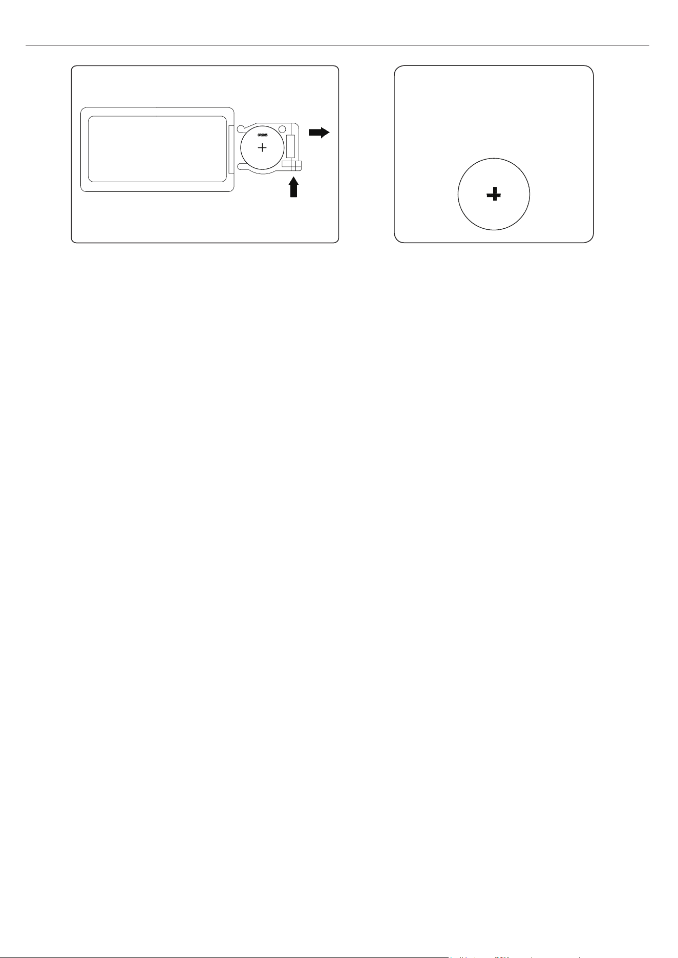
61
28WM373 REV2.0
CR2025
CÓMO REEMPLAZAR LAS BATERÍAS DEL CONTROL REMOTO:
PRECAUCIÓN:
• No ingiera la batería.
• La batería no es recargable y no debe recargarse.
• La batería se debe insertar en la polaridad correcta.
• La batería agotada se debe retirar del producto.
• Compre siempre el tamaño correcto y el grado de batería más adecuado para el uso especicado.
• Limpie los contactos de las baterías y los del dispositivo antes de instalar las baterías.
• Retire la batería usada inmediatamente.
• No incinere las baterías. Estas podrían explotar o ltrarse.
ADVERTENCIA: riesgo de quemadura química. Mantenga las baterías alejadas de los niños.
Este producto contiene una batería de celda de disco/botón de litio. Si se ingiere o ingresa al cuerpo una
batería de celda de disco/botón de litio nueva o usada, puede ocasionar quemaduras internas graves y
puede causar la muerte en tan solo 2 horas. Siempre vuelva a asegurar el compartimiento de las baterías.
Si el compartimiento de la batería no cierra con rmeza, deje de usar el producto, retire las baterías y
manténgalas lejos del alcance de los niños. Si cree que las baterías pueden haberse ingerido o que se
encuentran en el interior de cualquier parte del cuerpo, busque atención médica inmediata.
a) Las celdas se deben desechar adecuadamente, lo que incluye mantenerlas fuera del alcance de
los niños; y
b) incluso las celdas usadas pueden causar lesiones.
Se incluye 1 batería CR2025
NOTA: eliminación de las baterías
Siempre elimine las baterías en un
punto de reciclaje adecuado.

62
28WM373 REV2.0
LISTA DE PIEZAS DE REPUESTO
PIEZA NOMBRE DE LA PIEZA NO
NÚMERO DE PIEZA
1
Sensor del termostato 1
Y21-S307-P186SS
2
Ensamble del soplador/calentador 1
Y21-S307-P01SS
3
Placa de circuitos principal 1
Y21-S307-P15SS
4 Cable del panel de control
1 Y21-S327-P187SS
5
Cable de conexión del lecho de
brasas
1
Y21-S307-P188SS
6
Motor de accionamiento del generador de
llamas
1
Y21-S307-P189SS
7
Placa de circuitos de la llama 1 Y21-S307-P40SS
8
Placa de circuitos del panel de control 1
Y21-S307-P32SS
9
Control remoto
1 P185
10 Juego de leños izquierdo 1 Y21-S307-P20LSS
11 Juego de leños derecho 1 Y21-S307-P20RSS
12 Juego de leños central 1 Y21-S307-P20MSS
13 Lecho de brasas 1 Y21-S327-P21SS
14 Accesorio roscado 40 PH-THRZNC001
15 Deslizador del piso 4 PH-GLDBRW001
Para obtener piezas de repuesto, llame a nuestro Departamento de Servicio al Cliente al
1-866-439-9800, de lunes a domingo de 8 a.m. a 8 p.m., hora estándar del Este. También puede
ponerse en contacto con nosotros en [email protected].
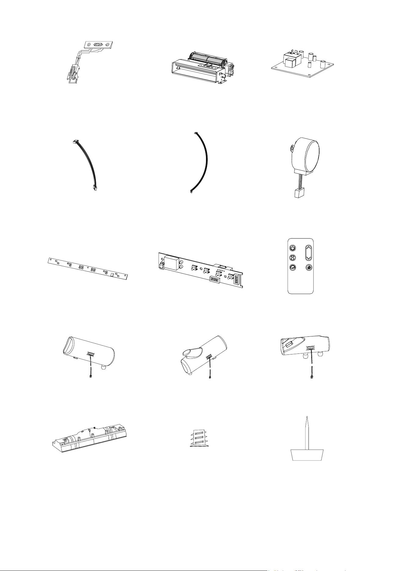
63
28WM373 REV2.0
Impreso en Vietnam
1
6
3
5
7
10
14
13
8 9
4
2
11
15
12